EP2849428A1 - Image processing device, image processing method, image processing program, and storage medium - Google Patents
Image processing device, image processing method, image processing program, and storage medium Download PDFInfo
- Publication number
- EP2849428A1 EP2849428A1 EP13850725.6A EP13850725A EP2849428A1 EP 2849428 A1 EP2849428 A1 EP 2849428A1 EP 13850725 A EP13850725 A EP 13850725A EP 2849428 A1 EP2849428 A1 EP 2849428A1
- Authority
- EP
- European Patent Office
- Prior art keywords
- matrix
- frame image
- motion
- image
- component
- Prior art date
- Legal status (The legal status is an assumption and is not a legal conclusion. Google has not performed a legal analysis and makes no representation as to the accuracy of the status listed.)
- Granted
Links
- 238000012545 processing Methods 0.000 title claims abstract description 95
- 238000003672 processing method Methods 0.000 title claims description 12
- 239000011159 matrix material Substances 0.000 claims abstract description 440
- 238000004364 calculation method Methods 0.000 claims abstract description 155
- 238000005096 rolling process Methods 0.000 claims abstract description 81
- 238000013519 translation Methods 0.000 claims abstract description 69
- 238000003384 imaging method Methods 0.000 claims abstract description 21
- 230000009467 reduction Effects 0.000 claims description 20
- 238000000034 method Methods 0.000 description 60
- 230000008569 process Effects 0.000 description 45
- 238000012937 correction Methods 0.000 description 34
- 230000006870 function Effects 0.000 description 27
- 238000013500 data storage Methods 0.000 description 14
- 230000007547 defect Effects 0.000 description 11
- 230000014509 gene expression Effects 0.000 description 8
- 238000013461 design Methods 0.000 description 6
- 238000000926 separation method Methods 0.000 description 6
- 238000010586 diagram Methods 0.000 description 4
- 230000000694 effects Effects 0.000 description 4
- 238000005259 measurement Methods 0.000 description 4
- PXFBZOLANLWPMH-UHFFFAOYSA-N 16-Epiaffinine Natural products C1C(C2=CC=CC=C2N2)=C2C(=O)CC2C(=CC)CN(C)C1C2CO PXFBZOLANLWPMH-UHFFFAOYSA-N 0.000 description 3
- 230000009471 action Effects 0.000 description 3
- 230000008859 change Effects 0.000 description 3
- 238000006243 chemical reaction Methods 0.000 description 3
- 230000007613 environmental effect Effects 0.000 description 3
- 238000001914 filtration Methods 0.000 description 3
- 230000009466 transformation Effects 0.000 description 3
- NAWXUBYGYWOOIX-SFHVURJKSA-N (2s)-2-[[4-[2-(2,4-diaminoquinazolin-6-yl)ethyl]benzoyl]amino]-4-methylidenepentanedioic acid Chemical compound C1=CC2=NC(N)=NC(N)=C2C=C1CCC1=CC=C(C(=O)N[C@@H](CC(=C)C(O)=O)C(O)=O)C=C1 NAWXUBYGYWOOIX-SFHVURJKSA-N 0.000 description 2
- 230000008030 elimination Effects 0.000 description 2
- 238000003379 elimination reaction Methods 0.000 description 2
- 238000013507 mapping Methods 0.000 description 2
- 238000004091 panning Methods 0.000 description 2
- 239000007787 solid Substances 0.000 description 2
- 238000012935 Averaging Methods 0.000 description 1
- 101000582320 Homo sapiens Neurogenic differentiation factor 6 Proteins 0.000 description 1
- 102100030589 Neurogenic differentiation factor 6 Human genes 0.000 description 1
- 230000008901 benefit Effects 0.000 description 1
- 238000004891 communication Methods 0.000 description 1
- 230000001419 dependent effect Effects 0.000 description 1
- 230000006872 improvement Effects 0.000 description 1
- 230000007246 mechanism Effects 0.000 description 1
- 239000004065 semiconductor Substances 0.000 description 1
Images


Classifications
-
- G06T3/10—
-
- G—PHYSICS
- G06—COMPUTING; CALCULATING OR COUNTING
- G06T—IMAGE DATA PROCESSING OR GENERATION, IN GENERAL
- G06T3/00—Geometric image transformation in the plane of the image
- G06T3/40—Scaling the whole image or part thereof
-
- G06T5/92—
-
- H—ELECTRICITY
- H04—ELECTRIC COMMUNICATION TECHNIQUE
- H04N—PICTORIAL COMMUNICATION, e.g. TELEVISION
- H04N23/00—Cameras or camera modules comprising electronic image sensors; Control thereof
- H04N23/60—Control of cameras or camera modules
- H04N23/68—Control of cameras or camera modules for stable pick-up of the scene, e.g. compensating for camera body vibrations
- H04N23/681—Motion detection
- H04N23/6811—Motion detection based on the image signal
-
- H—ELECTRICITY
- H04—ELECTRIC COMMUNICATION TECHNIQUE
- H04N—PICTORIAL COMMUNICATION, e.g. TELEVISION
- H04N23/00—Cameras or camera modules comprising electronic image sensors; Control thereof
- H04N23/60—Control of cameras or camera modules
- H04N23/68—Control of cameras or camera modules for stable pick-up of the scene, e.g. compensating for camera body vibrations
- H04N23/682—Vibration or motion blur correction
- H04N23/683—Vibration or motion blur correction performed by a processor, e.g. controlling the readout of an image memory
-
- H—ELECTRICITY
- H04—ELECTRIC COMMUNICATION TECHNIQUE
- H04N—PICTORIAL COMMUNICATION, e.g. TELEVISION
- H04N23/00—Cameras or camera modules comprising electronic image sensors; Control thereof
- H04N23/60—Control of cameras or camera modules
- H04N23/68—Control of cameras or camera modules for stable pick-up of the scene, e.g. compensating for camera body vibrations
- H04N23/689—Motion occurring during a rolling shutter mode
Abstract
Description
- The present invention relates to an image processing device, an image processing method, an image processing program, and a storage medium.
- As a conventional image processing device, there is a known device which determines an appropriate clipping region to be clipped from a shot frame image, in order to eliminate influence of camera shake or the like during an image-shooting operation of a video (e.g., cf. Patent Literature 1). The image processing device described in
Patent Literature 1 is configured to detect motion data indicative of how much a frame image deviates from a reference frame image (e.g., a preceding input frame image) and to move or deform the clipping region according to the detected motion data, thereby to make a correction to keep the clipping region stationary relative to motion of a camera. This image processing device calculates a movement amount or a deformation amount in view of motion according to four degrees of freedom comprising rotation, enlargement/reduction and parallel translation, or in view of motion according to six degrees of freedom comprising parallel translation, rotation, enlargement/reduction and shear, and adjusts the clipping region, based thereon. - For the image processing device, there is a known technique of accurately calculating a rolling shutter distortion component and a camera motion component (e.g., cf. Patent Literature 2). The image processing device described in
Patent Literature 2 is configured to model a global motion vector expressed in the form of an affine transformation matrix, by substituting the vector into a component separation expression which separately expresses the rolling shutter distortion component and the camera motion component with use of unknown component parameters. Then, the device solves equations obtained from the modelled component separation expression to obtain each of the component parameters and individually and accurately calculate the rolling shutter distortion component and the camera motion component. -
- Patent Literature 1: Japanese Patent Application Laid-open Publication No.
2007-226643 - Patent Literature 2: Japanese Patent Application Laid-open Publication No.
2010-193302 - In the case where a region is clipped from a frame image as in the image processing device described in
Patent Literature 1, it is necessary to more accurately calculate the motion of the camera (camera motion component), based on motion data between frame images, in order to obtain a more suitable region as the region to be clipped. It is conceivable herein to use the image processing device described inPatent Literature 2 to model the whole motion of the camera, thereby to accurately calculate the camera motion component. Then, it is conceivable to consider the motion, for example, according to six degrees of freedom as degrees of freedom for deformation of the image, as in the image processing device described inPatent Literature 2. This allows us to obtain accurate motion data closer to the actual camera motion than in the case where the motion is considered according to four degrees of freedom. However, if correction were made for only a defect due to camera motion not intended by a user, design of a correction filter for correction of the camera shake or the like could become more complicated with increase in degrees of freedom. For example, when the imaging device (camera) is panned or tilted, it is necessary to change a level of correction for each degree of freedom and eliminate influence of the camera shake and the like, while letting the clipping region follow the panning or tilting motion. - Furthermore,
Patent Literature 2 discloses only the component separation expression in the case where the motion vector is limited to the affine transformation according to six degrees of freedom; for this reason, when the motion vector is expressed by perspective projection, it is necessary to model the vector by a component separation expression different from the affine transformation. Since the image processing device described inPatent Literature 2 needs to prepare the component separation expressions depending upon formats of motion data as described above, application thereof might be limited. Furthermore, if in the image processing device described inPatent Literature 2 an inaccurate global motion vector is substituted into the component separation expression, it will naturally result in deriving the rolling shutter distortion component and the camera motion component being inaccurate, and thus the device can fail to perform robust processing. - In the present technical field, there are demands for an image processing device, image processing method, image processing program, and storage medium which readily and suitably determine a region to be clipped from a frame image and which facilitate design of a correction filter for correction of the camera shake and the like.
- Specifically, an image processing device according to one aspect of the present invention is an image processing device which sets in a frame image generated by an imaging device, a region of a size smaller than the frame image, and which corrects a position or a shape of the region according to motion of the imaging device to generate an output frame image. The device comprises an input unit, a motion acquisition unit, a matrix operation unit, and a drawing unit. The input unit implements sequential input of a first frame image and a second frame image. The motion acquisition unit acquires motion data between the first frame image and the second frame image. The matrix operation unit calculates a projection matrix to project the output frame image to the second frame image, from a first matrix including a rolling shutter distortion component, a second matrix including at least one of a parallel translation component in directions perpendicular to an image-shooting direction and a rotation component with respect to the image-shooting direction, and an auxiliary matrix including a motion component not included in the first matrix and the second matrix. The drawing unit generates the output frame image from the second frame image by using the projection matrix. The matrix operation unit comprises a first calculation unit, a second calculation unit, and an auxiliary matrix calculation unit. The first calculation unit calculates the first matrix for the projection matrix by using the motion data. The second calculation unit calculates the second matrix for the projection matrix by using the motion data, the first matrix, and, the second matrix in the past. The auxiliary matrix calculation unit calculates the auxiliary matrix for the projection matrix by using the motion data, the first matrix, and, the auxiliary matrix in the past.
- In this image processing device, the motion of deformation of the image is handled by dividing it into at least either the parallel translation component or the rotation component, the rolling shutter distortion component, and the other component, and they are individually calculated. The first calculation unit calculates with some degree of accuracy the first matrix including the rolling shutter distortion component by using the motion data. The second calculation unit calculates the second matrix including at least one of the parallel translation component and the rotation component by using the motion data, the first matrix, and, the second matrix in the past. The auxiliary matrix calculation unit calculates the auxiliary matrix including the motion component not included in the first matrix and the second matrix by using the motion data, the first matrix, and, the auxiliary matrix in the past. In this manner, the image processing device can decompose the motion data into three parts and individually calculate them in the calculation procedure, thus enabling the processing according to the motion component. For example, the rolling shutter distortion component can be excluded from the correction target to be subjected to removal of the camera shake and the like. This can facilitate design of computation cost for correction and correction filters. Furthermore, since the parallel translation component or the rotation component, and the component included in the auxiliary matrix are calculated by their respective formulas, it becomes feasible to independently correct the parallel translation component or the rotation component strongly reflecting human intention, and the other rest component without relation to each other. Namely, the motion component strongly reflecting the human intention and the other motion component can be corrected by different filters, and thus it becomes feasible to simultaneously achieve elimination of the defect due to the motion not intended by the user and appropriate follow-up to a camera work. Since the corrections for the respective components are independent, the correction filters can be readily designed. Even if the format of motion data is changed or there is inaccurate data, the auxiliary matrix can be made to include a changed portion in the format of motion data or an error portion, and thus the device is compatible with all formats of motion data. Furthermore, since there is no restriction on a calculation method of motion by the second calculation unit, it is possible, for example, to apply a calculation method that is not accurate but robust, to the calculation method of motion by the second calculation unit. In this case, robust processing can be performed as a whole of the image processing device.
- In one embodiment, the first calculation unit may calculate the first matrix for the projection matrix, based on the parallel translation component included in the motion data. When the rolling shutter distortion component is assumed to be attributed to only the parallel translation component as in this case, the rolling shutter distortion component can be readily and quickly estimated as a relatively accurate component.
- In one embodiment, the auxiliary matrix may include a component to convert a quadrilateral to a trapezoid. When deformation of the image is considered as one according to eight degrees of freedom as in this case, the auxiliary matrix is made to include the component to convert a quadrilateral to a trapezoid, whereby the defect due to the motion not intended by the user can be more naturally eliminated without affecting the processing to follow the motion intended by the user.
- In one embodiment, the auxiliary matrix may include an enlargement/reduction component. For example, when the enlargement/reduction component is less likely to be used in image-shooting scenes, the auxiliary matrix is made to include the enlargement/reduction component, whereby the defect due to the motion not intended by the user can be more naturally eliminated without affecting the processing to follow the motion intended by the user.
- In one embodiment, the second matrix may include an enlargement/reduction component. For example, when the enlargement/reduction component is more likely to be used in image-shooting scenes, the second matrix is made to include the enlargement/reduction component, whereby the processing to follow the motion intended by the user can be more accurately carried out.
- In one embodiment, the motion acquisition unit may acquire an output value from a gyro sensor. When the device is configured to operate in collaboration with hardware as in this case, it can also perform suitable image processing.
- An image processing method according to another aspect of the present invention is an image processing method which sets in a frame image generated by an imaging device, a region of a size smaller than the frame image, and which corrects a position or a shape of the region according to motion of the imaging device to generate an output frame image. The method comprises an input step, a motion acquisition step, a matrix operation step, and a drawing step. The input step is to implement sequential input of a first frame image and a second frame image. The motion acquisition step is to acquire motion data between the first frame image and the second frame image. The matrix operation step is to calculate a projection matrix to project the output frame image to the second frame image, from a first matrix including a rolling shutter distortion component, a second matrix including at least one of a parallel translation component in directions perpendicular to an image-shooting direction and a rotation component with respect to the image-shooting direction, and an auxiliary matrix including a motion component not included in the first matrix and the second matrix. The drawing step is to generate the output frame image from the second frame image by using the projection matrix. The matrix operation step has a first calculation step, a second calculation step, and an auxiliary matrix calculation step. The first calculation step is to calculate the first matrix for the projection matrix by using the motion data. The second calculation step is to calculate the second matrix for the projection matrix by using the motion data, the first matrix, and, the second matrix in the past. The auxiliary matrix calculation step is to calculate the auxiliary matrix for the projection matrix by using the motion data, the first matrix, and, the auxiliary matrix in the past.
- An image processing program according to another aspect of the present invention is an image processing program which lets a computer function to set in a frame image generated by an imaging device, a region of a size smaller than the frame image, and to correct a position or a shape of the region according to motion of the imaging device to generate an output frame image. The program lets the computer function as an input unit, a motion acquisition unit, a matrix operation unit, and a drawing unit. The input unit implements sequential input of a first frame image and a second frame image. The motion acquisition unit acquires motion data between the first frame image and the second frame image. The matrix operation unit calculates a projection matrix to project the output frame image to the second frame image, from a first matrix including a rolling shutter distortion component, a second matrix including at least one of a parallel translation component in directions perpendicular to an image-shooting direction and a rotation component with respect to the image-shooting direction, and an auxiliary matrix including a motion component not included in the first matrix and the second matrix. The drawing unit generates the output frame image from the second frame image by using the projection matrix. The matrix operation unit comprises a first calculation unit, a second calculation unit, and an auxiliary matrix calculation unit. The first calculation unit calculates the first matrix for the projection matrix by using the motion data. The second calculation unit calculates the second matrix for the projection matrix by using the motion data, the first matrix, and, the second matrix in the past. The auxiliary matrix calculation unit calculates the auxiliary matrix for the projection matrix by using the motion data, the first matrix, and, the auxiliary matrix in the past.
- A storage medium according to another aspect of the present invention is a computer-readable storage medium storing an image processing program. The image processing program lets a computer function to set in a frame image generated by an imaging device, a region of a size smaller than the frame image, and to correct a position or a shape of the region according to motion of the imaging device to generate an output frame image. The program lets the computer function as an input unit, a motion acquisition unit, a matrix operation unit, and a drawing unit. The input unit implements sequential input of a first frame image and a second frame image. The motion acquisition unit acquires motion data between the first frame image and the second frame image. The matrix operation unit calculates a projection matrix to project the output frame image to the second frame image, from a first matrix including a rolling shutter distortion component, a second matrix including at least one of a parallel translation component in directions perpendicular to an image-shooting direction and a rotation component with respect to the image-shooting direction, and an auxiliary matrix including a motion component not included in the first matrix and the second matrix. The drawing unit generates the output frame image from the second frame image by using the projection matrix. The matrix operation unit comprises a first calculation unit, a second calculation unit, and an auxiliary matrix calculation unit. The first calculation unit calculates the first matrix for the projection matrix by using the motion data. The second calculation unit calculates the second matrix for the projection matrix by using the motion data, the first matrix, and, the second matrix in the past. The auxiliary matrix calculation unit calculates the auxiliary matrix for the projection matrix by using the motion data, the first matrix, and, the auxiliary matrix in the past.
- The image processing method, image processing program, and storage medium described above achieve the same effects as the image processing device according to one aspect of the present invention described above.
- The various aspects and embodiments of the present invention provide the image processing device, image processing method, image processing program, and storage medium which readily and suitably determine the region to be clipped from the frame image and which facilitate design of the correction filter for correction of the camera shake and the like.
-
-
Fig. 1 is a functional block diagram of a portable terminal equipped with an image processing device according to an embodiment. -
Fig. 2 is a hardware configuration diagram of the portable terminal on which the image processing device according to the embodiment is mounted. -
Fig. 3 is a schematic drawing for explaining a principle of camera shake correction. -
Fig. 4 is a schematic drawing for explaining motion of an image. -
Fig. 5 is a schematic drawing for explaining a relation among a reference frame image, a target frame image, and an output frame image. -
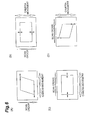
Fig. 6 is a schematic drawing for explaining rolling shutter distortion. (A) shows distortion of a subject in a case where a scanning order of scanning of X-directional lines is set along a Y-direction and where a camera is moved along an X-direction. (B) shows distortion of the subject in a case where the scanning order of scanning of X-directional lines is set along the Y-direction and where the camera is moved along the Y-direction. (C) shows distortion of the subject in a case where the scanning order of scanning of Y-directional lines is set along the X-direction and where the camera is moved along the X-direction. (D) shows distortion of the subject in a case where the scanning order of scanning of Y-directional lines is set along the X-direction and where the camera operation is moved along the Y-direction. -
Fig. 7 is a schematic drawing for explaining a system without rolling shutter distortion. -
Fig. 8 is a schematic drawing for explaining a method for calculating a distortion coefficient. -
Fig. 9 is a graph showing a relation between moving frame image and distortion count. -
Fig. 10 is a graph showing a relation between motion matrix component and movement amount. -
Fig. 11 is a schematic drawing for explaining a parallel translation component and a rotation component. -
Fig. 12 is a conceptual drawing showing a relation between an input frame image and an output frame image. -
Fig. 13 is a flowchart for explaining the operation of the image processing device according to the embodiment. - Embodiments will be described below with reference to the accompanying drawings. Identical or equivalent portions will be denoted by the same reference signs in the drawings, without redundant description.
- An image processing device according to the present embodiment is a device that outputs an image after eliminating the defect such as the camera shake or the rolling shutter distortion of the image. The image processing device according to the present embodiment is adopted, for example, in continuous shooting of images or in video shooting. The image processing device according to the present embodiment is suitably mounted on a mobile terminal with limited resources, e.g., a cell phone, a digital camera, a PDA (Personal Digital Assistant), or the like, but, without having to be limited to these, it may be mounted, for example, on an ordinary computer system. The below will describe the image processing device to be mounted on a portable terminal equipped with a camera function, as an example, in view of easiness of understanding of description.
-
Fig. 1 is a function block diagram of aportable terminal 2 provided with theimage processing device 1 according to the present embodiment. Theportable terminal 2 shown inFig. 1 is, for example, a mobile terminal carried by a user and has a hardware configuration shown inFig. 2. Fig. 2 is a hardware configuration diagram of theportable terminal 2. As shown inFig. 2 , theportable terminal 2 is constructed, from the physical view, as an ordinary computer system including a CPU (Central Processing Unit) 100, main storage devices such as a ROM (Read Only Memory) 101 and a RAM (Random Access Memory) 102, aninput device 103 such as a camera or a keyboard, anoutput device 104 such as a display, anauxiliary storage device 105 such as a hard disc, and so on. Each of below-described functions of theportable terminal 2 andimage processing device 1 is implemented by loading predetermined computer software on the hardware such as theCPU 100,ROM 101, andRAM 102, thereby letting theinput device 103 andoutput device 104 operate under control of theCPU 100, and carrying out readout and writing of data from and into the main storage devices andauxiliary storage device 105. Although the above device was described as the hardware configuration of theportable terminal 2, theimage processing device 1 may be constructed as an ordinary computer system including theCPU 100, the main storage devices such as theROM 101 andRAM 102, theinput device 103, theoutput device 104, theauxiliary storage device 105, and so on. In addition, theportable terminal 2 may be equipped with a communication module or the like. - As shown in
Fig. 1 , theportable terminal 2 has a camera (imaging device) 20, theimage processing device 1, animage storage unit 22, a precedingdata storage unit 23, and adisplay unit 21. Thecamera 20 has a function to generate an image. Thecamera 20 to be used herein is, for example, a CMOS pixel sensor or the like and generates an image by the focal plane shutter method. Namely, thecamera 20 is configured to scan an image vertically or horizontally to achieve input of pixel values. Thecamera 20 has a continuous image-shooting function, for example, to repetitively generate images at predetermined intervals from the timing designated by a user's manipulation or the like. Namely, thecamera 20 has a function to acquire not only still pictures (still frame images) but also videos (continuous moving frame images). The user can freely shoot images, for example, by sliding thecamera 20, rotating the camera from an origin at a predetermined position, tilting the camera in a left, right, up, or down direction, or combining the foregoing actions. Thecamera 20 has a function to output to theimage processing device 1, for example, a shot frame image every time of taking of an image. Thedisplay unit 21 is a display device that can display an image or a video. - The
image processing device 1 has a function to output a frame image after eliminating the defect such as the camera shake or the rolling shutter distortion. Let us define, for example as shown in (A) and (B) ofFig. 3 , frame images continuously generated by thecamera 20, as framei-1 and framei and center positions thereof as Cfi-1 and Cfi. Theimage processing device 1 sets a clipping region Ki-1 of a size smaller than the frame image framei-1. For example, the size of the clipping region Ki-1 is from 70 to 90% of the size of the frame image framei-1. A center position of the clipping region Ki-1 is Cri-1. This clipping region Ki-1 is output as an output frame image. Next, let us suppose that thecamera 20 is moved from the image-shooting position shown in (A) to the image-shooting position shown in (B) (or shifted in an upper right direction indicated by a solid arrow in (B) ofFig. 3 ). In this case, the camera generates a frame image framei shifted upper right from the frame image framei-1. At this point, theimage processing device 1 sets a clipping region Ki at a position where the motion between the frame image framei-1 and the frame image framei is cancelled out (or shifts the clipping region in a lower left direction indicated by a dotted arrow in (B) ofFig. 3 ). This makes the center position Cri of the current clipping region Ki approximately equal to the center position Cri-1 of the preceding clipping region Ki-1 and thus the output frame image is generated as if it were still, and is output to thedisplay unit 21. - The following will describe the details of the
image processing device 1. As shown inFig. 1 , theimage processing device 1 has aninput unit 10, amotion acquisition unit 11, a calculation unit (matrix operation unit) 30, and adrawing unit 17. - The
input unit 10 has a function to implement input of a frame image generated by thecamera 20. Theinput unit 10 has, for example, a function to implement input of a frame image generated by thecamera 20, every time of taking of an image. Furthermore, theinput unit 10 has a function to store the frame image into theimage storage unit 22 provided in theportable terminal 2. In addition, theinput unit 10 has a function to output an input frame image to themotion acquisition unit 11. - The
motion acquisition unit 11 has a function to acquire motion between frame images, using an input frame image (second frame image) and a frame image (first frame image) generated immediately before the foregoing input frame image or generated previously. The first frame image is, for example, one stored in theimage storage unit 22. Themotion acquisition unit 11 refers to theimage storage unit 22 to obtain a frame image input in the past, as a reference frame image, and acquires relative motion data between the reference frame image and the input frame image. It is noted that the reference frame image may be a frame image having an overlap of not less than a predetermined area with the input frame image as a processing target. For this reason, themotion acquisition unit 11 does not have to change the reference frame image every input of the input frame image and may be configured to update the reference frame image for the next or subsequent input frame image when the current reference frame image comes to lose the overlap of not less than the predetermined area with the input frame image as a processing target. If the motion is acquired with reference to three or more frame images, instead of two frame images, the immediately preceding input frame image is defined as a temporary reference frame image and the motion is acquired by comparing the input frame image as a processing target with the already-set reference frame image and the temporary reference frame image. Themotion acquisition unit 11 compares the frame images to acquire motion data P (observations), for example, according to eight degrees of freedom. Themotion acquisition unit 11 outputs the motion data P to thecalculation unit 30. It is noted that themotion acquisition unit 11 may acquire the motion data P by taking in an output value of a gyro sensor provided in theportable terminal 2. The gyro sensor has a function to detect and output the motion data P between the reference frame image and the input frame image. - The motion according to eight degrees of freedom will be summarized below.
Fig. 4 is a schematic drawing for explaining the motion according to eight degrees of freedom. As shown inFig. 4 , for example, when an image before deformation is assumed to be square, the image can be deformed into (A) to (H) because of motion of thecamera 20. (A) is enlargement/reduction, (B) parallelogram (in the horizontal direction), (C) parallelogram (in the vertical direction), (D) rotation, (E) parallel translation (in the horizontal direction), (F) parallel translation (in the vertical direction), (G) trapezoid (in the horizontal direction), and (H) trapezoid (in the vertical direction). For this reason, theimage processing device 1 set the clipping region Ki according to the foregoing deformation. - The following will describe a relationship among the motion data P, the clipping region Ki-1, the clipping region Ki, and a projection matrix.
Fig. 5 is a schematic drawing showing a relationship among the reference frame image framei-1, the processing target frame image framei, their respective clipping regions Ki-1, Ki, and the output frame image out-framei. InFig. 5 , the motion data (motion vector) between the reference frame image framei-1 and the processing target frame image framei is represented by P. The motion data P is known data acquired by themotion acquisition unit 11. Furthermore, a conversion expression (projection matrix) to associate the clipping region Ki-1 of the reference frame image framei-1 with the output frame image out-framei-1 is represented by Pdst i-1. The projection matrix Pdst i-1 will also be referred to hereinafter as a preceding projection matrix or first projection matrix. Since the projection matrix Pdst i-1 consists of values calculated in the preceding operation, it is known. The projection matrix Pdst i-1 is stored, for example, in the precedingdata storage unit 23. In this case, as shown inFig. 5 , a conversion expression (projection matrix) Pdst i to associate the clipping region Ki of the frame image framei with the output frame image out-framei can be calculated by Formula (1) below, using the motion data P and the first projection matrix Pdst i-1.
[Math 1]
The projection matrix Pdst i will also be referred to hereinafter as a second projection matrix. - It is noted herein that the condition of Formula (1) is a mode of completely fixing the clipping region. It is necessary, however, to eliminate the defect such as the camera shake, while following the motion intended by the user (e.g., parallel movement, panning, or tilting of the camera). For example, a high-pass filer is used to subject the motion intended by the user and the motion to cause the defect, to filtering. In this case, the second projection matrix Pdst i is given by Formula (2) below.
[Math 2]
In this formula HPF represents the high-pass filter. Specifically, the filter passes high-frequency components resulting from the camera shake or the like so as to fix the screen but cuts low-frequency components resulting from the motion intended by the user, so as to make the screen follow the user's motion. - However, the motion data P includes the rolling shutter distortion component.
Fig. 6 is a schematic drawing for explaining the rolling shutter distortion component. The rolling shutter distortion is a phenomenon, as shown in (A) ofFig. 6 , in which when thecamera 20 is horizontally moved relative to a subject, the subject is horizontally distorted into a parallelogram. When thecamera 20 is vertically moved, the rolling shutter distortion appears so as to vertically enlarge or reduce the subject, as shown in (B) ofFig. 6 . Since the rolling shutter distortion component always needs to be corrected, it is the component that should always pass through the high-pass filter. Namely, the high-pass filter does not have to be applied to the rolling shutter distortion component. Therefore, a scheme to be constructed is one which follows the user-intended motion but eliminates the defect such as the camera shake, in a state in which the rolling shutter distortion component is separated. -
Fig. 7 is a schematic drawing for explaining the foregoing scheme. As shown inFig. 7 , let us assume that there is a processing target frame image framei moved by the motion data P from the reference frame image framei-1. InFig. 7 , known values are indicated by solid arrows and unknown values by dotted arrows. An arrow P represents the motion data (motion vector), which is known. An arrow Di-1 is an operator (first matrix Di-1) indicative of the rolling shutter distortion component of the reference frame image framei-1. The first matrix Di-1 consists of values determined in the preceding operation and is thus known. The first matrix Di-1 is stored, for example, in the precedingdata storage unit 23. By using the first matrix Di-1, the frame image in the input image system can be converted into the frame image in a system without rolling shutter distortion. -
Fig. 7 shows the "system without rolling shutter distortion" and the system does not have to be a system from which the rolling shutter distortion is completely removed, but may be a system from which the rolling shutter distortion is reduced to a certain degree. For example, when the first matrix Di-1 consists of accurate values, the frame image in the input image system is converted into the frame image in the system in which the rolling shutter distortion is perfectly absent. However, when the first matrix Di-1 does not consist of accurate values, the frame image in the input image system is converted into the frame image in the system in which the rolling shutter distortion is reduced. In this manner, the accuracy of the first matrix Di-1 affects a level of how much the rolling shutter distortion component is not taken into consideration. For this reason, when the first matrix Di-1 that is provisionally probable is used, the frame image can be converted into the system with reduced rolling shutter distortion and, in this case, it becomes possible to achieve a state in which the rolling shutter distortion component is separated to some extent. Namely, the scheme in the present embodiment allows for some error in removal of the rolling shutter distortion. - In
Fig. 7 , an image resulting from reduction of the rolling shutter distortion from the reference frame image framei-1 is designated by RS_framei-1. A matrix Si-1 indicated by an arrow is a vector (projection matrix) that associates the output frame image out-framei with the clipping region of RS_framei-1. Since the projection matrix Si-1 consists of values determined in the preceding operation, it is known. The projection matrix Si-1 can be calculated, for example, using the first projection matrix Pdst i-1 and the first matrix Di-1 determined in the preceding operation. The projection matrix Si-1 is stored, for example, in the precedingdata storage unit 23. The projection matrix Si-1 will also be referred to hereinafter as a first projection matrix in the system from which the rolling shutter distortion component is reduced. - As shown in
Fig. 7 , if we can convert the processing target frame image framei into an image RS_framei in the system without rolling shutter distortion, we can calculate motion data N in the system without rolling shutter distortion. The motion data N will also be referred to thereinafter as provisional motion data. Once we find the motion data N in the system with reduced rolling shutter distortion, a projection matrix Si in the system with reduced rolling shutter distortion (a second projection matrix in the system with reduced rolling shutter distortion), which associates the clipping region of RS_framei with the output frame image out-framei, can be expressed by Formula (3) below, similar to Formula (2).
[Math 3]
- Using the projection matrix Si in the system with reduced rolling shutter distortion, the second projection matrix Pdst i is expressed by Formula (4) below.
[Math 4]
- The conversion into the system with reduced rolling shutter distortion as described above allows us to apply the high-pass filter only to N-Si-1 in no consideration of the rolling shutter distortion.
- The
calculation unit 30 is an operation unit for realizing the foregoing scheme. Namely, thecalculation unit 30 calculates the second projection matrix Pdst i to project the output frame image to the second frame image, using the preceding data already calculated and stored in the precedingdata storage unit 23 and the current data as measurements. - The below will describe a situation in which the preceding
data storage unit 23 stores the first matrix Di-1 indicative of the rolling shutter distortion component, the preceding motion data NPRE in the system with reduced rolling shutter distortion between frame images which have been input before the input of the second frame image, the preceding second matrix and preceding correction matrix between frame images input before input of the second frame image, and, the projection matrix Si-1 in the system with reduced rolling shutter distortion. The second matrix and correction matrix will be detailed later. - The
calculation unit 30 calculates the second projection matrix Pdst i to project the output frame image to the second frame image, from the first matrix Di including the rolling shutter distortion component, the second matrix including at least one of a parallel translation component in directions perpendicular to the image-shooting direction and a rotation component with respect to the image-shooting direction, and an auxiliary matrix not including the motion components included in the first matrix Di and the second matrix. Namely, thecalculation unit 30 calculates the second projection matrix Pdst i in the separated state into the first matrix Di, the second matrix, and the auxiliary matrix independently of each other. Thecalculation unit 30 has afirst calculation unit 12, asecond calculation unit 13, and an auxiliarymatrix calculation unit 14. - The
first calculation unit 12 calculates the first matrix Di including the rolling shutter distortion component. Thefirst calculation unit 12 has a function to calculate the rolling shutter distortion component, based on the parallel translation component. The distortion amount increases according to increase in speed of translation of thecamera 20. From this fact, it can be said that the rolling shutter distortion can be estimated using the speed of translation of thecamera 20. The speed of translation of thecamera 20 can be estimated using an amount of parallel translation between frames. Therefore, thefirst calculation unit 12 calculates the first matrix Di including the rolling shutter distortion component, for example, based on the parallel translation amount included in the motion data P. When the preceding motion data is denoted by Pi-1 and the current motion data by Pi, the parallel translation amount may be assumed to be an average of parallel translation amounts included in the motion data Pi-1 and the motion data Pi. The rolling shutter distortion component is expressed by Formula (5) below, where a coordinate system with distortion is represented by (xi, yi, 1)t and a coordinate system without distortion by (Xi, Yi, 1)t.
[Math 5]
- As shown in Formula (5) above, the value of Y affects the distortion component. It is noted herein that dx i and dy i included in the rolling shutter distortion component represent the parallel translation component of the image and α is a distortion coefficient. The distortion coefficient α is a value calculated by dividing a duration of time for retrieving one line of a frame image by the sum of a duration of time for retrieving the entire frame image and a duration of time up to a start of retrieval of the next frame image. In other words, the distortion coefficient α is a value calculated by dividing the duration for retrieval of one line of a frame image by a duration from a time of a start of retrieval for the first line of the frame image to a time of a start of retrieval for the first line of the next frame image. The distortion coefficient α varies depending upon specifications of the pixel sensor in the
camera 20 and/or settings for drive of the pixel sensor. For example, each of pixel sensors has different setting information, e.g., such as the scan speed, frame rate, exposure duration, pixel size, direction of scanning lines, zoom ratio, f-value, ON/OFF of mechanical camera shake correction mechanism, duration from taking of a frame to output, reading speed, reading direction, and so on. For this reason, it is necessary to preliminarily calculate the distortion coefficient α for each of image-shooting conditions including the various settings of the imaging device (image sensor), image-shooting modes, or environmental conditions, prior to the estimation of the distortion. In the pixel sensor, where tL represents a time difference between adjacent lines and tF a time difference between adjacent frames, the distortion coefficient α can be calculated by the below formula. It is noted that the time difference tF between adjacent frames can be derived based on the frame rate of a moving frame image sequence.
[Math 6]
- When NL represents the number of lines of the frame image (the height of the image), the following inequality holds.
[Math 7]
- The above inequality can be modified as follows.
[Math 8]
- As understood from the above, the upper limit of the distortion coefficient α can be determined when the number NL of lines of the frame image is known.
- A method for calculating the distortion coefficient α will be described below.
Fig. 8 is a schematic drawing for explaining the method for calculating the distortion coefficient α. As shown inFig. 8 , the distortion coefficient α is calculated using a still frame image frameb and a moving frame image sequence framei. The still frame image and a moving frame image are compared to obtain how much distortion is generated and, further a parallel translation amount between moving frame images is obtained, thereby a correlation between the distortion and the parallel translation amount is obtained. The distortion coefficient α is calculated from this correlation. - Specifically, the still frame image frameb is first generated with the subject and the
camera 20 being kept stationary. Next, the subject or thecamera 20 is moved to generate a moving frame image sequence: frame0, frame1, frame2, ... , framei-1, framei. The distortion amount in the moving frame image framei can be calculated by calculating a motion matrix Mb→i from the still frame image frameb to the moving frame image framei. The distortion amount is expressed by Formula (6) below, where a coordinate system for the still frame image frameb is defined by (xb, yb, 1) and a coordinate system for the moving frame image framei by (xi, yi, 1).
[Math 9]
- When it is assumed herein that the motion matrix Mb→i consists of only the parallel translation component and the distortion component, the distortion amount can be approximated to Formula (7) below.
[Math 10]
- Let us compare Formula (5) with Formula (7). In Formula (7), the distortion component is m01 b→i and m11 b→1. On the other hand, in Formula (5), the origin of the distortion component is the parallel translation amounts (dx i, dy i)t being the motion component between continuous frames. To determine the parallel translation amounts, a motion matrix Mi-1→i is determined from the moving frame image framei and the moving frame image framei-1 one frame before it. A relation between the moving frame image framei and the moving frame image framei-1 one frame before it can be expressed by Formula (8) below.
[Math 11]
- Using above Formula (8), the motion component (m02 i-1→i, m12 i-1→i)t between the frames may be defined as the parallel translation component (dx i, dyi)t. Furthermore, parallel translation amounts of center coordinates of the moving frame image framei may be defined as (dx i, dy i)t. Yet furthermore, the parallel translation amounts may be determined by calculating first parallel translation amounts using the frame image framei and the immediately preceding frame image framei-1 among the continuous frame images, calculating second parallel translation amounts using the frame image framei and the immediately subsequent frame image framei-1, and calculating averages of the first parallel translation amounts and the second parallel translation mounts (by weighted averaging, polynomial approximation, or the like) as the parallel translation amounts. Use of average parallel translation amounts allows improvement in accuracy. As (dx i, dy i)t are calculated, the distortion coefficient α can be expressed by Formulas (9), (10) below.
[Math 12]
[Math 13]
- Now, we can determine the distortion coefficient α by measuring m01 b→i, m11 b→i, dx i, and dy i in one frame image framei and using Formula (9) or Formula (10). It is assumed, however, that m01 b→1, m11 b→1, dx i, and dy i as measurements for determining the distortion coefficient α may include error. For this reason, the distortion coefficient α may be calculated as follows: a distortion coefficient obtained for one frame image framei is defined as a provisional distortion coefficient, the provisional distortion coefficient is determined for each of a plurality of frame images, and these provisional distortion coefficients are used to obtain an accurate distortion coefficient α with convergence of error.
Fig. 9 shows framei on the horizontal axis and distortion coefficient αi on the vertical axis. As shown inFig. 9 , the provisional distortion coefficients αi are determined for a variety of framei and an average of them (weighted average) may be adopted as the distortion coefficient α. As another example, the provisional distortion coefficients αi are determined for a variety of framei and the median of them may be adopted as the distortion coefficient α.Fig. 10 shows translation amount dx i on the horizontal axis and motion matrix component m01 b→i on the vertical axis. As shown inFig. 10 , while they are plotted on a two-dimensional plane with the coordinate axes of the parallel translation amount and the rolling shutter distortion component, the distortion coefficient α may be determined from a slope of a regression line represented by Formula (10). Even in cases where the values of m01 b→i, m11 b→i, dx i, and dy i as measurements are small and where the error has significant influence, the distortion coefficient α can be determined with accuracy by the foregoing techniques. It should be noted herein that the provisional distortion coefficient αi and the distortion coefficient α need to be not more than the aforementioned upper limit (the inverse of the number NL of lines of the frame image). For this reason, if the provisional distortion coefficient αk of a predetermined frame image framek is larger than the inverse of the number NL of lines of the frame image, the distortion coefficient α may be calculated by the technique based on the average, median, or regression line as described above, after a correction is made to define the inverse of the number NL of lines of the frame image as the provisional distortion coefficient αk for the frame image framek. Alternatively, if the provisional distortion coefficient αk of a predetermined frame image framek is larger than the inverse of the number NL of lines of the frame image, the distortion coefficient α may be calculated by the technique based on the average, median, or regression line as described above, while excluding the provisional distortion coefficient αk for the frame image framek. Furthermore, if the derived distortion coefficient α is larger than the inverse of the number NL of lines of the frame image, a correction may be made to define the inverse of the number NL of lines of the frame image as the distortion coefficient α. The rolling shutter distortion appears in different ways, depending upon specifications of the pixel sensor and/or the settings for drive of the pixel sensor. When the distortion coefficient α is calculated for each of the settings of thecamera 20 or the pixel sensor by the aforementioned technique, we can estimate the rolling shutter distortion accurately while reflecting the conditions peculiar to thecamera 20. When the distortion coefficient α is calculated using actual measurements, the device may be configured to also store information regarding under what image-shooting environmental conditions the distortion coefficient α was calculated. Examples of the image-shooting environmental conditions include "brightness" or "temperature" or the like. - The
first calculation unit 12 is configured to be able to refer to the camera information storage unit storing the distortion coefficients α calculated by the above method. For example, it has a table of distortion coefficients α in association with device setting values. It may have a table of distortion coefficients α in association with device setting values and image-shooting environments. Thefirst calculation unit 12 refers to the camera information storage unit to acquire the value of the distortion coefficient α according to the setting of the pixel sensor and estimates the rolling shutter distortion component with use of the camera motion component. The current setting information of the pixel sensor and the information regarding the image-shooting environment may be acquired, for example, from thecamera 20. If the camera information storage unit stores the duration of retrieval of one line of the frame image and the duration of retrieval of the entire frame image and the duration up to retrieval of the next frame image in association with the setting information and the information regarding the image-shooting environment, the distortion coefficient α may be calculated based on the information stored in the camera information storage unit, instead of the direct acquisition of the distortion coefficient α from the camera information storage unit. - Since the
first calculation unit 12 derives the first matrix Di in consideration of only the parallel translation as described above, it can obtain approximately accurate values though the first matrix Di thus calculated does not consist of true values. Thefirst calculation unit 12 outputs the calculated first matrix Di to thesecond calculation unit 13, the auxiliarymatrix calculation unit 14, and thedrawing unit 17. - Once the first matrix Di is calculated, the processing target frame image framei can be converted to the image RS_framei in the system without rolling shutter distortion. This allows us to also derive the motion data N in the system with reduced rolling shutter distortion with the use of the motion data P and the first matrix Di, by using the relation shown in
Fig. 7 . - By calculating the motion data N, it becomes feasible to apply the high-pass filter only to N·Si-1 in no consideration of the rolling shutter distortion. However, since N·Si-1 is a matrix, if the high-pass filter is applied in this matrix state of N·Si-1, processing can possibly become complicated. For this reason, the
calculation unit 30 handles the motion component of N·Si-1 by dividing it into the motion of thecamera 20 reflecting the user's intention and the other motion component. Thesecond calculation unit 13 calculates the second matrix including the motion of thecamera 20 reflecting the user's intention. The auxiliarymatrix calculation unit 14 calculates the auxiliary matrix. Thesecond calculation unit 13 and the auxiliarymatrix calculation unit 14 are configured so as to be able to execute the operations in the system without rolling shutter distortion, using the calculated first matrix Di. - The
second calculation unit 13 estimates that the motion of thecamera 20 reflecting the user's intention is at least one of the parallel translation component and the rotation component. It is noted that thesecond calculation unit 13 may calculate the motion while definitely separating the parallel translation component and the rotation component as components or may calculate a complex motion component (combinational component) of the parallel translation component and the rotation component. For example, when z-axis is defined as an axis extending in the image-shooting direction and x-axis and y-axis are defined as axes extending in directions perpendicular to the image-shooting direction, thesecond calculation unit 13 may calculate a combinational component of the parallel translation component and the rotation component about the x-axis and the y-axis. Thesecond calculation unit 13 may estimate the motion in consideration of an enlargement/reduction component as well, depending upon scenes to be shot. Namely, the second matrix may include only the parallel translation component, or may include only the rotation component, or may include only the parallel translation component and the rotation component, or may include the enlargement/reduction component in addition to the parallel translation component and the rotation component. -
Fig. 11 is a schematic drawing for explaining the parallel translation component and the rotation component. The motion of thecamera 20 is dependent on image-shooting scenes, but most of camera works consist of the parallel translation component and the rotation component.Fig. 11 shows a relation between a coordinate system (x, y) of the output frame image out-frame and a coordinate system (X, Y) of the processing target frame image frame. InFig. 11 , z-axis is defined as an axis extending in the image-shooting direction, and x-axis and y-axis are defined as axes extending in directions perpendicular to the image-shooting direction. When the z-axis is defined as an axis extending in the image-shooting direction and the x-axis and y-axis are defined as axes extending in the directions perpendicular to the image-shooting direction, the parallel translation component is a component of movement in directions parallel to the x-axis, y-axis, and z-axis. The rotation component is at least one rotation component about the x-axis, y-axis, and z-axis and is thus at least one of a yaw component, a roll component, and a pitch component. - The
second calculation unit 13 calculates a user motion matrix Ac for calculating the second matrix. The user motion matrix Ac is a matrix used for calculation of the second matrix and includes at least one of the parallel translation component in the directions perpendicular to the image-shooting direction and the rotation component with respect to the image-shooting direction. For example, as shown inFig. 11 , thesecond calculation unit 13 calculates the user motion matrix Ac to make correspondence between the center coordinates (0, 0) of the output frame image out-frame and the center (0, 0) of the frame image frame as the second frame image. Thesecond calculation unit 13 can calculate the user motion matrix Ac from the motion data P. Specifically, thesecond calculation unit 13 specifies the center coordinates of the frame image frame, for example, using the known first projection matrix Pdst i-1 to project the output frame image out-frame to the first frame image, and the motion data P. Then, thesecond calculation unit 13 effects parallel translation and rotation of the coordinates (x, y) of the output frame image out-frame to calculate the user motion matrix Ac for projection to the center (X, Y) of the frame image frame. The yaw component, roll component, and pitch component can be estimated with some degree of accuracy, for example, from movement amounts near the center and the focal length. Since the motion is restricted to parallel translation and rotation herein, the resulting user motion matrix Ac does not consist of true values but can be obtained as approximately correct values. Thesecond calculation unit 13 outputs the calculated user motion matrix Ac to the auxiliarymatrix calculation unit 14. - The
second calculation unit 13 has a function to calculate the second matrix by making a correction for the user motion matrix Ac. Thesecond calculation unit 13 has a function to remove the high-frequency components due to the camera shake, as to the motion of thecamera 20 that is considered to be intended by the user. Thesecond calculation unit 13 uses a first filter to remove frequency components attributed to a camera work. The first filter is, for example, a high-pass filter. Furthermore, thesecond calculation unit 13, for example as shown inFig. 12 , may apply a spring model to function so that as the clipping region Ki becomes closer to the outer edge frame of the frame image framei, it is positioned to be closer to the center position, so as to realize the follow-up to the camera work. For example, thesecond calculation unit 13 may apply the first filter with an action to position the region closer to the center position in proportion to the square of the distance from the outer edge, to the user motion matrix Ac to obtain the second matrix. Thesecond calculation unit 13 may be configured to adjust the spring constants (proportionality coefficients) in the x-axis, y-axis, and z-axis. Thesecond calculation unit 13 may also be configured to set friction higher near the center of the frame image frame1. This setting allows the device to improve stability of follow-up. - The auxiliary
matrix calculation unit 14 calculates a "rest motion matrix Bc" of the motion data N, using the user motion matrix Ac. Components included in the matrix Bc can include a rest component that is not expressed by the first matrix Di and the user motion matrix Ac, for example, among the eight components shown inFig. 4 , and an error component that is not accurately expressed by the first matrix Di and the user motion matrix Ac (e.g., an error component of the rolling shutter distortion component, an error component of the rotation component, and so on). Namely, the rest motion matrix Bc varies depending upon the set degrees of freedom and the user motion matrix Ac. For example, in a case where the motion is interpreted according to eight degrees of freedom and the user motion matrix Ac includes the enlargement/reduction component, the rest motion matrix Bc includes a component to convert a quadrilateral into a trapezoid ((G) and (H) shown inFig. 4 ) and an error component. For example, in a case where the motion is interpreted according to eight degrees of freedom and the user motion matrix Ac does not include the enlargement/reduction component, the rest motion matrix Bc includes the enlargement/reduction component, the component to convert a quadrilateral into a trapezoid ((G) and (H) shown inFig. 4 ), and the error component. For example, in a case where the motion is interpreted according to six degrees of freedom and the user motion matrix Ac does not include the enlargement/reduction component, the rest motion matrix Bc includes the enlargement/reduction component and the error component. For example, in a case where the motion is interpreted according to six degrees of freedom and the user motion matrix Ac includes the enlargement/reduction component, the rest motion matrix Bc includes only the error component. - The auxiliary
matrix calculation unit 14 calculates the motion matrix Bc including the rest motion component, using N·Si-1 calculated using the first projection matrix Si-1 and the motion data N in the system with reduced rolling shutter distortion component, and the user motion matrix Ac. The below will explain a case where the user motion matrix Ac mainly includes the rotation component (the yaw component yi, the pitch component pi, and the roll component ri). In this case, the auxiliarymatrix calculation unit 14 calculates the motion matrix Bc including the rest motion component, using Formula (11) or (12) below.
[Math 14]

- Specifically, the auxiliary
matrix calculation unit 14 handles the motion component of N·Si-1 by dividing it into the user motion matrix Ac including the yaw component yi, the pitch component pi, and the roll component ri, and the rest motion matrix Bc including the other motion component li, to individually calculate the user motion matrix Ac and substitute the result into above Formula (11) or (12), thereby obtaining the component li. The below will describe a case where the auxiliarymatrix calculation unit 14 uses Formula (11). - The auxiliary
matrix calculation unit 14 has a function to correct the calculated "rest motion matrix Bc" to obtain the auxiliary matrix. The rest motion matrix Bc is a matrix including the auxiliary component for motion, and can include an error or ignored component. For this reason, the rest motion matrix Bc is ideally an identity matrix to implement identity mapping. Therefore, a question is at what timing the rest motion matrix Bc should be converged to the identity matrix. The second correction unit 16 makes a correction to gradually decrease the error, i.e., a correction to gradually change the rest motion matrix Bc to the identity matrix, instead of a sudden correction to the identity matrix. For example, it may calculate the difference between the identity matrix and the rest motion matrix Bc and effects a correction to make the difference 80%. For example, the auxiliarymatrix calculation unit 14 may use a high-pass filter to implement the above processing. When the sudden correction to the identity matrix is avoided in this manner, it becomes feasible to avoid the output frame image having unnatural motion eventually. - The above-described processing of the
second calculation unit 13 and the auxiliarymatrix calculation unit 14 is summarized as follows.
[Math 15]
- Namely, the second matrix is a matrix resulting from the application of the high-pass filter to the user motion matrix Ac including the yaw component yi, the pitch component pi, and the roll component ri, and the auxiliary matrix is a matrix resulting from the application of the high-pass filter to the rest motion matrix Bc. A complicated single-variable filter may be designed only as the high-pass filter to be applied to the yaw component yi, the pitch component pi, and the roll component ri. Namely, an accurate filter is designed only for the motion of the
camera 20 reflecting the user's intention. Here, the high-pass filter may be designed, for example, using the data stored in the precedingdata storage unit 23. Thesecond calculation unit 13 outputs the calculated second matrix, for example, every calculation of the second matrix to store it in the precedingdata storage unit 23. Thereby, the high-pass filter to derive the second matrix is designed, for example, with use of the past second matrix stored in the precedingdata storage unit 23. Furthermore, the auxiliarymatrix calculation unit 14 applies the high-pass filter to the rest motion components li. Here, the high-pass filter may be designed, for example, using the data stored in the precedingdata storage unit 23. The auxiliarymatrix calculation unit 14 outputs the calculated auxiliary matrix, for example, every calculation of the auxiliary matrix to store it in the precedingdata storage unit 23. Thereby, the high-pass filter to derive the auxiliary matrix is designed, for example, with use of the past auxiliary matrix stored in the precedingdata storage unit 23. It is noted that, as described above, the high-pass filter to be applied to the rest motion component li may be so simply designed as to converge it to the identity matrix. Since we can make a distinction between the accurately designed filter and the moderately accurate filter in this manner, the overall filter design becomes easier. - The
calculation unit 30 derives the projection matrix Si in the system without rolling shutter distortion as described below, using the second matrix and the auxiliary matrix.
[Math 16]
- Then, the
calculation unit 30 derives the second projection matrix Pdst i to make correspondence between the output frame image out-framei and the input frame image framei, using the first matrix Di, the second matrix, and the auxiliary matrix.
[Math 17]
- The
drawing unit 17 calculates the clipping region Ki of the input frame image framei, using the second projection matrix Pdst i and outputs it as the output frame image out-framei to thedisplay unit 21. - The following will describe the operation of the
image processing device 1 according to the present embodiment.Fig. 13 is a flowchart showing the operation of theimage processing device 1 according to the present embodiment. The control processing shown inFig. 13 is carried out at the timing when the image-shooting function of theportable terminal 2 is turned on, and is repetitively carried out at predetermined intervals. In view of easiness of understanding of description, the input frame image as a processing target is assumed to be the second or subsequent input frame image. - As shown in
Fig. 13 , theimage processing device 1 first executes an image input process (S10: input step). In the process of S10, theinput unit 10 implements input of the input frame image framei from thecamera 20. After completion of the process of S10, the operation shifts to a motion data acquisition process (S12: motion acquisition step). - In the process of S12, the
motion acquisition unit 11 acquires the motion data P between the input frame image framei and the frame image framei-1. After completion of the process of S12, the operation shifts to a process of calculating the first matrix Di including the rolling shutter distortion component (S 14: first calculation step). - In the process of
S 14, thefirst calculation unit 12 calculates the first matrix Di including the rolling shutter distortion component, based on the motion data acquired in the process of S12. After completion of the process ofS 14, the operation shifts to a process of calculating the motion data N (S16). - In the process of S16, the
calculation unit 30 calculates the provisional motion data N, using the motion data P acquired in the process of S12 and the first matrix Di acquired in the process of S14. After completion of the process of S16, the operation shifts to a rotation component calculation process (S 18). - In the process of S18, the
second calculation unit 13 calculates the rotation component (user motion matrix Ac). The rotation component can be estimated with some degree of accuracy, for example, from the movement amount of the center position of the input frame image framei and the focal length. Calculation in the yaw direction will be explained as an example. When the movement amount in the x-axis direction is denoted by dmx and the focal length by dn, the component in the yaw direction can be simply calculated by the following formula.
[Math 18]
- After completion of the process of S18, the operation shifts to a process of filtering the user motion matrix Ac (S20: second calculation step).
- In the process of S20, the
second calculation unit 13 corrects the the user motion matrix Ac acquired in the process of S18, with the high-pass filter to obtain the second matrix. Specifically, thesecond calculation unit 13 refers to the precedingdata storage unit 23 to acquire the second matrix in the past, and obtains the second matrix, using the past second matrix and the motion matrix Ac. After completion of the process of S20, the operation shifts to a process of filtering the rest motion matrix Bc (S22: auxiliary matrix calculation step). - In the process of S22, the auxiliary
matrix calculation unit 14 calculates the rest motion matrix Bc and subjects the rest motion matrix Bc to the filter process, thereby obtaining the auxiliary matrix Bc. First, the auxiliarymatrix calculation unit 14 handles the motion component of N·Si-1 by dividing it into the user motion matrix Ac including the yaw component yi, the pitch component pi, and the roll component ri, and the rest motion matrix ri including the other motion component li, individually calculates the user motion matrix Ac and substitutes the result into the aforementioned Formula (11), thereby obtaining the component li as the rest motion matrix Bc. The auxiliarymatrix calculation unit 14 may be configured to refer to the precedingdata storage unit 23 to acquire the auxiliary matrix in the past, and obtains the auxiliary matrix, using the past auxiliary matrix and the motion matrix Ac. - In the process of S24, the
calculation unit 30 calculates the projection matrix Si in the system without rolling shutter distortion, using the second matrix acquired in the process of S20 and the auxiliary matrix acquired in the process of S22. After completion of the process of S24, the operation shifts to a process of calculating the drawing matrix (projection matrix) (S26). - In the process of S26, the
calculation unit 30 calculates the second projection matrix Pdst i in the input image system, using the projection matrix Si obtained in the process of S24, for example, as shown by the aforementioned Formula (4). After completion of the process of S26, the operation shifts to a drawing process (S28: drawing step). - In the process of S28, the
drawing unit 17 calculates the clipping region Ki of the input frame image framei with the use of the second projection matrix Pdst i acquired in the process of S26, and outputs the result as the output frame image out-framei to thedisplay unit 21. After completion of the process of S28, the operation shifts to a determination process (S30). - In the process of S30, the
image processing device 1 determines whether input of an image is finished. Theimage processing device 1 determines whether input of an image is finished, for example, based on whether the number of inputs reaches a predetermined input count, or, based on whether a predetermined time has elapsed since the preceding input. When it is determined in the process of S30 that input of an image is not finished, the operation shifts again to the process of S10. On the other hand, when it is determined in the process of S30 that input of an image is finished, the control processing shown inFig. 13 is terminated. By executing the control processing shown inFig. 13 , it becomes feasible to independently correct the parallel translation component and the rotation component strongly reflecting the human intention, and the other component and error component, without relation to each other. It is noted herein that the first calculation step, the second calculation step, and the auxiliary matrix calculation step correspond to a matrix operation step. - The below will describe an image processing program for letting the portable terminal (computer) 2 function as the
image processing device 1. - The image processing program has a main module, an input module, and an operation processing module. The main module is a part that generally controls the image processing. The input module makes the
portable terminal 2 operate so as to acquire an input image. The operation processing module has a motion acquisition module, a calculation module (first calculation module, second calculation module, and auxiliary matrix calculation module), and a drawing module. Functions realized by executing the mail module, input module, and operation processing module are the same as the functions of theinput unit 10,motion acquisition unit 11, calculation unit 30 (first calculation unit 12,second calculation unit 13, and auxiliary matrix calculation unit 14), and drawingunit 17, respectively, of the aforementionedimage processing device 1. - The image processing program is provided, for example, by a storage medium such as ROM, or by a semiconductor memory. Furthermore, the image processing program may be provided as a data signal through a network.
- As described above, the
image processing device 1, image processing method, and image processing program according to the present embodiment are configured to handle the motion of deformation of the image by separating it into at least either the parallel translation component or the rotation component, the rolling shutter distortion component, and the other component, and individually calculate each of them. Thefirst calculation unit 12 calculates with some accuracy the first matrix Di including the rolling shutter distortion component, using the motion data. Thesecond calculation unit 13 calculates with some accuracy the user motion matrix Ac including at least one of the parallel translation component in the directions perpendicular to the image-shooting direction and the rotation component with respect to the image-shooting direction, using the known first projection matrix Pdst i-1 to project the output frame image out-framei-1 to the reference frame image framei-1, and the motion data P. The auxiliarymatrix calculation unit 14 calculates the rest motion matrix Bc not including the motion component included in the first matrix Di and the user motion matrix Ac, using the first matrix Di, the user motion matrix Ac, and the first projection matrix Pdst i-1. Then, the user motion matrix Ac and the rest motion matrix Bc are corrected to calculate the second matrix and the auxiliary matrix. In this manner, theimage processing device 1 can decompose the motion data into three parts and individually calculate them in the calculation procedure, which makes the processing according to the motion component possible. For example, it becomes possible to exclude the rolling shutter distortion component to be removed, from the correction target to be subjected to removal of the camera shake or the like. This can facilitate design of computation cost for correction and correction filters. Furthermore, since the parallel translation component or the rotation component, and the component in the auxiliary matrix are calculated by the respective different formulas, it becomes feasible to independently correct the parallel translation component or the rotation component strongly reflecting the human intention, and the other remaining component without relation to each other. Namely, since the motion component strongly reflecting the human intention and the other motion component can be corrected by the different filters, it becomes feasible to simultaneously achieve elimination of the defect due to the motion not intended by the user, and appropriate follow-up to a camera work. Since the corrections for the respective components are independent, the correction filters can be readily designed. In addition, even if the format of motion data is changed or there is inaccurate data, it is possible to make the auxiliary matrix include a changed portion of the format of motion data or an error portion and thus the foregoing processing can be compatible with all formats of motion data. Since there are no restrictions on the calculation method of motion by the second calculation unit, a calculation method that is not accurate but robust can be applied to the calculation method of motion by the second calculation unit. In this case, robust processing can be carried out as a whole of theimage processing device 1. Furthermore, it becomes feasible to implement perfect electronic camera-shake correction. - Furthermore, the
image processing device 1, image processing method, and image processing program according to the present embodiment can make the correction to ideal values (or identity mapping), while taking advantage of the values of the rest motion matrix Bc. For this reason, it becomes feasible to more naturally eliminate the defect due to the motion not intended by the user. - In addition, the
image processing device 1, image processing method, and image processing program according to the present embodiment are configured to assume that the rolling shutter distortion component is attributed to the parallel translation component only, the rolling shutter distortion component can be readily and quickly estimated as a relatively accurate component. - The above-described embodiment shows an example of the image processing device according to the present invention. The image processing device according to the present invention is not limited only to the
image processing device 1 according to the embodiment, but may be one obtained by modifying the image processing device according to the embodiment or by applying it to other devices, without departing from the spirit and scope of the invention described in each of the claims. - For example, the foregoing embodiment described the example wherein the
camera 20 generates videos, but thecamera 20 may be one that continuously generates still images. Images implemented by theinput unit 10 may be images transmitted through a network from another device. - The above embodiment was described on the assumption that the images generated by the
camera 20 had the same size, but the size of the generated image may be different every time of generating of an image. - The above embodiment described the case where the image was deformed according to the eight degrees of freedom shown in
Fig. 4 , but the degrees of freedom do not have to be limited to the eight degrees but may be, for example, the six degrees of freedom shown in (A) to (F) inFig. 4 . - The above embodiment described the example where the
first calculation unit 12 estimated the rolling shutter distortion component and the example where thesecond calculation unit 13 estimated the parallel translation component and the rotation component, but, without having to be limited to the above techniques, it is possible to adopt various known methods. Furthermore, thefirst calculation unit 12 may be configured to estimate the rolling shutter distortion component, using the parallel translation component acquired by thesecond calculation unit 13. - The sequence of the flowchart described in the above embodiment can be modified as occasion may demand. For example, the process of S18 or the sequential processes of S18 and S20 may be carried out in parallel with the process of S14 or S16.
- The above embodiment showed the case where the projection matrix to associate the second frame image with the output frame image was calculated with the use of the first frame image and the second frame image, but the present invention does not have to be limited to it. Namely, the output frame image does not have to be successively generated with the input frame image, and there may be a time difference between the input frame image and a reference frame image for the output frame image. For example, a third frame image existing between the first frame image and the second frame image may be used as a processing target for generating the output frame image, to calculate the projection matrix to associate the third frame image with the output frame image. The third frame image may be processed in the same manner as the second frame image as described in the above embodiment, or the projection matrix to the third frame image may be calculated using not only the first frame image but also the second frame image. Namely, the projection matrix to the third frame image may be calculated using the first frame image which is past data with respect to the third frame image and the second frame image which is future data with respect to the third frame image.
- Furthermore, the above embodiment described the example wherein the high-pass filter was made to act on the motion data P and the first projection matrix Pdst i-1, for example, as shown by Formula (2), but the target of action of the high-pass filter may be modified as occasion may demand. For example, Formula (2) may be modified as follows.
[Math 19]
- In this case, the high-pass filter acts on the motion data N. In this case, Formula (13) is modified as follows.
[Math 20]
- As in this formula, the motion data N may be one in a divided form. Furthermore, the high-pass filter may be one that changes the coefficient of the high-pass filter, depending upon the clipping position.
- 1 image processing device; 10 input unit; 11 motion acquisition unit; 12 first calculation unit; 13 second calculation unit; 14 auxiliary matrix calculation unit; 17 drawing unit; 20 camera; 21 display unit; 22 image storage unit; 30 calculation unit (matrix operation unit).
Claims (9)
- An image processing device which sets in a frame image generated by an imaging device, a region of a size smaller than the frame image, and which corrects a position or a shape of the region according to motion of the imaging device to generate an output frame image, the image processing device comprising:an input unit that implements sequential input of a first frame image and a second frame image;a motion acquisition unit that acquires motion data between the first frame image and the second frame image;a matrix operation unit that calculates a projection matrix to project the output frame image to the second frame image, from a first matrix including a rolling shutter distortion component, a second matrix including at least one of a parallel translation component in directions perpendicular to an image-shooting direction and a rotation component with respect to the image-shooting direction, and an auxiliary matrix including a motion component not included in the first matrix and the second matrix; anda drawing unit that generates the output frame image from the second frame image by using the projection matrix,wherein the matrix operation unit comprises:a first calculation unit that calculates the first matrix for the projection matrix by using the motion data;a second calculation unit that calculates the second matrix for the projection matrix by using the motion data, the first matrix, and, the second matrix in the past; andan auxiliary matrix calculation unit that calculates the auxiliary matrix for the projection matrix by using the motion data, the first matrix, and, the auxiliary matrix in the past.
- The image processing device according to claim 1, wherein the first calculation unit calculates the first matrix for the projection matrix, based on the parallel translation component included in the motion data.
- The image processing device according to claim 1 or 2, wherein the auxiliary matrix includes a component to convert a quadrilateral to a trapezoid.
- The image processing device according to any one of claims 1 to 3, wherein the auxiliary matrix includes an enlargement/reduction component.
- The image processing device according to any one of claims 1 to 4, wherein the second matrix includes an enlargement/reduction component.
- The image processing device according to any one of claims 1 to 5, wherein the motion acquisition unit acquires an output value from a gyro sensor.
- An image processing method which sets in a frame image generated by an imaging device, a region of a size smaller than the frame image, and which corrects a position or a shape of the region according to motion of the imaging device to generate an output frame image, the image processing method comprising:an input step of implementing sequential input of a first frame image and a second frame image;a motion acquisition step of acquiring motion data between the first frame image and the second frame image;a matrix operation step of calculating a projection matrix to project the output frame image to the second frame image, from a first matrix including a rolling shutter distortion component, a second matrix including at least one of a parallel translation component in directions perpendicular to an image-shooting direction and a rotation component with respect to the image-shooting direction, and an auxiliary matrix including a motion component not included in the first matrix and the second matrix; anda drawing step of generating the output frame image from the second frame image by using the projection matrix,wherein the matrix operation step comprises:a first calculation step of calculating the first matrix for the projection matrix by using the motion data;a second calculation step of calculating the second matrix for the projection matrix by using the motion data, the first matrix, and, the second matrix in the past; andan auxiliary matrix calculation step of calculating the auxiliary matrix for the projection matrix by using the motion data, the first matrix, and, the auxiliary matrix in the past.
- An image processing program which lets a computer function to set in a frame image generated by an imaging device, a region of a size smaller than the frame image, and to correct a position or a shape of the region according to motion of the imaging device to generate an output frame image, the image processing program letting the computer function as:an input unit that implements sequential input of a first frame image and a second frame image;a motion acquisition unit that acquires motion data between the first frame image and the second frame image;a matrix operation unit that calculates a projection matrix to project the output frame image to the second frame image, from a first matrix including a rolling shutter distortion component, a second matrix including at least one of a parallel translation component in directions perpendicular to an image-shooting direction and a rotation component with respect to the image-shooting direction, and an auxiliary matrix including a motion component not included in the first matrix and the second matrix; anda drawing unit that generates the output frame image from the second frame image by using the projection matrix,wherein the matrix operation unit comprises:a first calculation unit that calculates the first matrix for the projection matrix by using the motion data;a second calculation unit that calculates the second matrix for the projection matrix by using the motion data, the first matrix, and, the second matrix in the past; andan auxiliary matrix calculation unit that calculates the auxiliary matrix for the projection matrix by using the motion data, the first matrix, and, the auxiliary matrix in the past.
- A computer-readable storage medium storing an image processing program which lets a computer function to set in a frame image generated by an imaging device, a region of a size smaller than the frame image, and to correct a position or a shape of the region according to motion of the imaging device to generate an output frame image, the image processing program letting the computer function as:an input unit that implements sequential input of a first frame image and a second frame image;a motion acquisition unit that acquires motion data between the first frame image and the second frame image;a matrix operation unit that calculates a projection matrix to project the output frame image to the second frame image, from a first matrix including a rolling shutter distortion component, a second matrix including at least one of a parallel translation component in directions perpendicular to an image-shooting direction and a rotation component with respect to the image-shooting direction, and an auxiliary matrix including a motion component not included in the first matrix and the second matrix; anda drawing unit that generates the output frame image from the second frame image by using the projection matrix,wherein the matrix operation unit comprises:a first calculation unit that calculates the first matrix for the projection matrix by using the motion data;a second calculation unit that calculates the second matrix for the projection matrix by using the motion data, the first matrix, and, the second matrix in the past; andan auxiliary matrix calculation unit that calculates the auxiliary matrix for the projection matrix by using the motion data, the first matrix, and, the auxiliary matrix in the past.
Applications Claiming Priority (2)
| Application Number | Priority Date | Filing Date | Title |
|---|---|---|---|
| PCT/JP2012/078591 WO2014068779A1 (en) | 2012-11-05 | 2012-11-05 | Image processing device, image processing method, image processing program, and storage medium |
| PCT/JP2013/079724 WO2014069632A1 (en) | 2012-11-05 | 2013-11-01 | Image processing device, image processing method, image processing program, and storage medium |
Publications (3)
| Publication Number | Publication Date |
|---|---|
| EP2849428A1 true EP2849428A1 (en) | 2015-03-18 |
| EP2849428A4 EP2849428A4 (en) | 2015-07-15 |
| EP2849428B1 EP2849428B1 (en) | 2016-10-19 |
Family
ID=50626742
Family Applications (1)
| Application Number | Title | Priority Date | Filing Date |
|---|---|---|---|
| EP13850725.6A Active EP2849428B1 (en) | 2012-11-05 | 2013-11-01 | Image processing device, image processing method, image processing program, and storage medium |
Country Status (6)
| Country | Link |
|---|---|
| US (1) | US9639913B2 (en) |
| EP (1) | EP2849428B1 (en) |
| JP (1) | JP5906493B2 (en) |
| KR (1) | KR101624450B1 (en) |
| CN (1) | CN104247395B (en) |
| WO (2) | WO2014068779A1 (en) |
Cited By (3)
| Publication number | Priority date | Publication date | Assignee | Title |
|---|---|---|---|---|
| EP3413555A1 (en) * | 2017-06-08 | 2018-12-12 | Ricoh Company Ltd. | Image processing method and device as well as computer program and non-transitory computer-readable medium |
| WO2019240988A1 (en) * | 2018-06-14 | 2019-12-19 | Google Llc | Camera area locking |
| US11196929B2 (en) | 2018-08-20 | 2021-12-07 | Sony Semiconductor Solutions Corporation | Signal processing device, imaging device, and signal processing method |
Families Citing this family (25)
| Publication number | Priority date | Publication date | Assignee | Title |
|---|---|---|---|---|
| US9736374B2 (en) * | 2013-09-19 | 2017-08-15 | Conduent Business Services, Llc | Video/vision based access control method and system for parking occupancy determination, which is robust against camera shake |
| JP6448218B2 (en) * | 2014-05-12 | 2019-01-09 | キヤノン株式会社 | IMAGING DEVICE, ITS CONTROL METHOD, AND INFORMATION PROCESSING SYSTEM |
| FR3023956B1 (en) * | 2014-07-18 | 2018-01-12 | Safran Electronics & Defense Sas | METHOD AND DEVICE FOR PROCESSING HIGH FREQUENCY MOVEMENTS IN AN OPTRONIC SYSTEM |
| KR102264840B1 (en) * | 2014-11-27 | 2021-06-15 | 삼성전자주식회사 | Video frame encoding circuit, encoding method thereof and video data transmitting and receiving system including the same |
| US9912868B2 (en) * | 2015-09-15 | 2018-03-06 | Canon Kabushiki Kaisha | Image-blur correction apparatus, tilt correction apparatus, method of controlling image-blur correction apparatus, and method of controlling tilt correction apparatus |
| JP6652300B2 (en) * | 2016-01-14 | 2020-02-19 | キヤノン株式会社 | Image processing apparatus, imaging apparatus, and control method |
| JP2018037944A (en) * | 2016-09-01 | 2018-03-08 | ソニーセミコンダクタソリューションズ株式会社 | Imaging control device, imaging apparatus, and imaging control method |
| CN108184048B (en) | 2016-12-08 | 2020-06-23 | 株式会社摩如富 | Image processing apparatus and method |
| JP6699902B2 (en) * | 2016-12-27 | 2020-05-27 | 株式会社東芝 | Image processing apparatus and image processing method |
| JP6960238B2 (en) * | 2017-04-28 | 2021-11-05 | キヤノン株式会社 | Image stabilization device and its control method, program, storage medium |
| US10534609B2 (en) | 2017-08-18 | 2020-01-14 | International Business Machines Corporation | Code-specific affiliated register prediction |
| US10884746B2 (en) | 2017-08-18 | 2021-01-05 | International Business Machines Corporation | Determining and predicting affiliated registers based on dynamic runtime control flow analysis |
| US10719328B2 (en) | 2017-08-18 | 2020-07-21 | International Business Machines Corporation | Determining and predicting derived values used in register-indirect branching |
| US10884747B2 (en) | 2017-08-18 | 2021-01-05 | International Business Machines Corporation | Prediction of an affiliated register |
| US10896030B2 (en) | 2017-09-19 | 2021-01-19 | International Business Machines Corporation | Code generation relating to providing table of contents pointer values |
| US10705973B2 (en) | 2017-09-19 | 2020-07-07 | International Business Machines Corporation | Initializing a data structure for use in predicting table of contents pointer values |
| US11061575B2 (en) | 2017-09-19 | 2021-07-13 | International Business Machines Corporation | Read-only table of contents register |
| US10884929B2 (en) | 2017-09-19 | 2021-01-05 | International Business Machines Corporation | Set table of contents (TOC) register instruction |
| US10725918B2 (en) | 2017-09-19 | 2020-07-28 | International Business Machines Corporation | Table of contents cache entry having a pointer for a range of addresses |
| US10713050B2 (en) | 2017-09-19 | 2020-07-14 | International Business Machines Corporation | Replacing Table of Contents (TOC)-setting instructions in code with TOC predicting instructions |
| US10620955B2 (en) | 2017-09-19 | 2020-04-14 | International Business Machines Corporation | Predicting a table of contents pointer value responsive to branching to a subroutine |
| US20190297265A1 (en) * | 2018-03-21 | 2019-09-26 | Sawah Innovations Inc. | User-feedback video stabilization device and method |
| KR102581210B1 (en) * | 2019-01-10 | 2023-09-22 | 에스케이하이닉스 주식회사 | Method for processing image signal, image signal processor, and image sensor chip |
| US11716537B2 (en) * | 2019-03-28 | 2023-08-01 | Sony Group Corporation | Image processing device, image processing method, and program |
| US11711613B2 (en) * | 2021-04-27 | 2023-07-25 | Qualcomm Incorporated | Image alignment for computational photography |
Family Cites Families (18)
| Publication number | Priority date | Publication date | Assignee | Title |
|---|---|---|---|---|
| US5696848A (en) * | 1995-03-09 | 1997-12-09 | Eastman Kodak Company | System for creating a high resolution image from a sequence of lower resolution motion images |
| JP2002236924A (en) | 2001-02-07 | 2002-08-23 | Gen Tec:Kk | Movement tracking method and its device or the like for three dimensional object using two dimensional continuous image |
| KR100574227B1 (en) | 2003-12-18 | 2006-04-26 | 한국전자통신연구원 | Apparatus and method for separating object motion from camera motion |
| US7880769B2 (en) * | 2004-02-13 | 2011-02-01 | Qualcomm Incorporated | Adaptive image stabilization |
| JP4620607B2 (en) | 2006-02-24 | 2011-01-26 | 株式会社モルフォ | Image processing device |
| US8054335B2 (en) * | 2007-12-20 | 2011-11-08 | Aptina Imaging Corporation | Methods and system for digitally stabilizing video captured from rolling shutter cameras |
| JP5189678B2 (en) * | 2008-04-22 | 2013-04-24 | コア ロジック,インコーポレイテッド | Image stabilization apparatus and method for moving image |
| JP5215818B2 (en) * | 2008-11-13 | 2013-06-19 | キヤノン株式会社 | Imaging apparatus, control method thereof, and program |
| JP4915424B2 (en) * | 2009-02-19 | 2012-04-11 | ソニー株式会社 | Image processing apparatus, camera motion component calculation method, image processing program, and recording medium |
| JP4915423B2 (en) | 2009-02-19 | 2012-04-11 | ソニー株式会社 | Image processing apparatus, focal plane distortion component calculation method, image processing program, and recording medium |
| JP5487722B2 (en) * | 2009-05-25 | 2014-05-07 | ソニー株式会社 | Imaging apparatus and shake correction method |
| EP2489180A1 (en) * | 2009-10-14 | 2012-08-22 | CSR Technology Inc. | Method and apparatus for image stabilization |
| JP2011114407A (en) * | 2009-11-24 | 2011-06-09 | Sony Corp | Image processing apparatus, image processing method, program, and recording medium |
| US8179446B2 (en) * | 2010-01-18 | 2012-05-15 | Texas Instruments Incorporated | Video stabilization and reduction of rolling shutter distortion |
| JP5683839B2 (en) | 2010-05-17 | 2015-03-11 | セミコンダクター・コンポーネンツ・インダストリーズ・リミテッド・ライアビリティ・カンパニー | Imaging device control circuit |
| JP5249377B2 (en) * | 2011-03-22 | 2013-07-31 | キヤノン株式会社 | Imaging apparatus, control method therefor, and program |
| US8823813B2 (en) * | 2011-06-06 | 2014-09-02 | Apple Inc. | Correcting rolling shutter using image stabilization |
| US9460495B2 (en) * | 2012-04-06 | 2016-10-04 | Microsoft Technology Licensing, Llc | Joint video stabilization and rolling shutter correction on a generic platform |
-
2012
- 2012-11-05 WO PCT/JP2012/078591 patent/WO2014068779A1/en active Application Filing
-
2013
- 2013-11-01 JP JP2014544608A patent/JP5906493B2/en active Active
- 2013-11-01 CN CN201380020123.5A patent/CN104247395B/en active Active
- 2013-11-01 KR KR1020147028881A patent/KR101624450B1/en active IP Right Grant
- 2013-11-01 WO PCT/JP2013/079724 patent/WO2014069632A1/en active Application Filing
- 2013-11-01 EP EP13850725.6A patent/EP2849428B1/en active Active
- 2013-11-01 US US14/397,579 patent/US9639913B2/en active Active
Cited By (8)
| Publication number | Priority date | Publication date | Assignee | Title |
|---|---|---|---|---|
| EP3413555A1 (en) * | 2017-06-08 | 2018-12-12 | Ricoh Company Ltd. | Image processing method and device as well as computer program and non-transitory computer-readable medium |
| US10674086B2 (en) | 2017-06-08 | 2020-06-02 | Ricoh Company, Ltd. | Image processing method and device and non-transitory computer-readable medium |
| WO2019240988A1 (en) * | 2018-06-14 | 2019-12-19 | Google Llc | Camera area locking |
| US10547790B2 (en) | 2018-06-14 | 2020-01-28 | Google Llc | Camera area locking |
| CN111837379A (en) * | 2018-06-14 | 2020-10-27 | 谷歌有限责任公司 | Camera zone locking |
| US11102413B2 (en) | 2018-06-14 | 2021-08-24 | Google Llc | Camera area locking |
| CN111837379B (en) * | 2018-06-14 | 2022-03-18 | 谷歌有限责任公司 | Method and system for capturing subareas and informing whether the subareas are changed by camera movement |
| US11196929B2 (en) | 2018-08-20 | 2021-12-07 | Sony Semiconductor Solutions Corporation | Signal processing device, imaging device, and signal processing method |
Also Published As
| Publication number | Publication date |
|---|---|
| WO2014069632A1 (en) | 2014-05-08 |
| JP5906493B2 (en) | 2016-04-20 |
| JPWO2014069632A1 (en) | 2016-09-08 |
| US9639913B2 (en) | 2017-05-02 |
| CN104247395A (en) | 2014-12-24 |
| US20150123990A1 (en) | 2015-05-07 |
| EP2849428B1 (en) | 2016-10-19 |
| KR101624450B1 (en) | 2016-05-25 |
| EP2849428A4 (en) | 2015-07-15 |
| KR20140138947A (en) | 2014-12-04 |
| CN104247395B (en) | 2017-05-17 |
| WO2014068779A1 (en) | 2014-05-08 |
Similar Documents
| Publication | Publication Date | Title |
|---|---|---|
| EP2849428B1 (en) | Image processing device, image processing method, image processing program, and storage medium | |
| US10506164B2 (en) | Depth information obtaining method and apparatus, and image acquisition device | |
| US8588546B2 (en) | Apparatus and program for producing a panoramic image | |
| US8976280B2 (en) | Distortion estimating image processing device, method, and non-transitory storage medium | |
| US9055217B2 (en) | Image compositing apparatus, image compositing method and program recording device | |
| US9986164B2 (en) | Camera shaking correction device and imaging apparatus with offset correction | |
| CN113436113B (en) | Anti-shake image processing method, device, electronic equipment and storage medium | |
| US8965105B2 (en) | Image processing device and method | |
| CN113556464B (en) | Shooting method and device and electronic equipment | |
| KR20150053495A (en) | Image correcting apparatus and method in photographing apparatus | |
| EP1968308B1 (en) | Image processing method, image processing program, image processing device, and imaging device | |
| US10623644B2 (en) | Image pick-up apparatus and control method thereof | |
| JP6730423B2 (en) | Image processing apparatus, image processing method, and image processing program | |
| JP2015041819A (en) | Imaging apparatus and its control method, program, and storage medium | |
| JP5279453B2 (en) | Image shake correction apparatus, imaging apparatus, and image shake correction method | |
| JP6739955B2 (en) | Image processing apparatus, image processing method, image processing program, and recording medium | |
| JP7408294B2 (en) | Imaging device, lens device, method of controlling the imaging device, and method of controlling the lens device | |
| JP7118818B2 (en) | Image processing method, image processing device, imaging device, and program | |
| EP3534605B1 (en) | Image processing device, image display device, and program | |
| JP2012147202A (en) | Image processing device and method therefor |
Legal Events
| Date | Code | Title | Description |
|---|---|---|---|
| PUAI | Public reference made under article 153(3) epc to a published international application that has entered the european phase |
Free format text: ORIGINAL CODE: 0009012 |
|
| 17P | Request for examination filed |
Effective date: 20141209 |
|
| AK | Designated contracting states |
Kind code of ref document: A1 Designated state(s): AL AT BE BG CH CY CZ DE DK EE ES FI FR GB GR HR HU IE IS IT LI LT LU LV MC MK MT NL NO PL PT RO RS SE SI SK SM TR |
|
| AX | Request for extension of the european patent |
Extension state: BA ME |
|
| RA4 | Supplementary search report drawn up and despatched (corrected) |
Effective date: 20150617 |
|
| RIC1 | Information provided on ipc code assigned before grant |
Ipc: H04N 5/232 20060101AFI20150611BHEP Ipc: G06T 3/00 20060101ALI20150611BHEP |
|
| DAX | Request for extension of the european patent (deleted) | ||
| GRAP | Despatch of communication of intention to grant a patent |
Free format text: ORIGINAL CODE: EPIDOSNIGR1 |
|
| INTG | Intention to grant announced |
Effective date: 20160524 |
|
| GRAS | Grant fee paid |
Free format text: ORIGINAL CODE: EPIDOSNIGR3 |
|
| GRAA | (expected) grant |
Free format text: ORIGINAL CODE: 0009210 |
|
| AK | Designated contracting states |
Kind code of ref document: B1 Designated state(s): AL AT BE BG CH CY CZ DE DK EE ES FI FR GB GR HR HU IE IS IT LI LT LU LV MC MK MT NL NO PL PT RO RS SE SI SK SM TR |
|
| REG | Reference to a national code |
Ref country code: GB Ref legal event code: FG4D |
|
| REG | Reference to a national code |
Ref country code: CH Ref legal event code: EP |
|
| REG | Reference to a national code |
Ref country code: AT Ref legal event code: REF Ref document number: 839187 Country of ref document: AT Kind code of ref document: T Effective date: 20161115 |
|
| REG | Reference to a national code |
Ref country code: IE Ref legal event code: FG4D |
|
| REG | Reference to a national code |
Ref country code: FR Ref legal event code: PLFP Year of fee payment: 4 |
|
| REG | Reference to a national code |
Ref country code: DE Ref legal event code: R096 Ref document number: 602013013112 Country of ref document: DE |
|
| REG | Reference to a national code |
Ref country code: NL Ref legal event code: MP Effective date: 20161019 |
|
| REG | Reference to a national code |
Ref country code: LT Ref legal event code: MG4D |
|
| PG25 | Lapsed in a contracting state [announced via postgrant information from national office to epo] |
Ref country code: LV Free format text: LAPSE BECAUSE OF FAILURE TO SUBMIT A TRANSLATION OF THE DESCRIPTION OR TO PAY THE FEE WITHIN THE PRESCRIBED TIME-LIMIT Effective date: 20161019 Ref country code: BE Free format text: LAPSE BECAUSE OF NON-PAYMENT OF DUE FEES Effective date: 20161130 |
|
| REG | Reference to a national code |
Ref country code: AT Ref legal event code: MK05 Ref document number: 839187 Country of ref document: AT Kind code of ref document: T Effective date: 20161019 |
|
| PG25 | Lapsed in a contracting state [announced via postgrant information from national office to epo] |
Ref country code: SE Free format text: LAPSE BECAUSE OF FAILURE TO SUBMIT A TRANSLATION OF THE DESCRIPTION OR TO PAY THE FEE WITHIN THE PRESCRIBED TIME-LIMIT Effective date: 20161019 Ref country code: NO Free format text: LAPSE BECAUSE OF FAILURE TO SUBMIT A TRANSLATION OF THE DESCRIPTION OR TO PAY THE FEE WITHIN THE PRESCRIBED TIME-LIMIT Effective date: 20170119 Ref country code: LT Free format text: LAPSE BECAUSE OF FAILURE TO SUBMIT A TRANSLATION OF THE DESCRIPTION OR TO PAY THE FEE WITHIN THE PRESCRIBED TIME-LIMIT Effective date: 20161019 Ref country code: GR Free format text: LAPSE BECAUSE OF FAILURE TO SUBMIT A TRANSLATION OF THE DESCRIPTION OR TO PAY THE FEE WITHIN THE PRESCRIBED TIME-LIMIT Effective date: 20170120 |
|
| PG25 | Lapsed in a contracting state [announced via postgrant information from national office to epo] |
Ref country code: ES Free format text: LAPSE BECAUSE OF FAILURE TO SUBMIT A TRANSLATION OF THE DESCRIPTION OR TO PAY THE FEE WITHIN THE PRESCRIBED TIME-LIMIT Effective date: 20161019 Ref country code: FI Free format text: LAPSE BECAUSE OF FAILURE TO SUBMIT A TRANSLATION OF THE DESCRIPTION OR TO PAY THE FEE WITHIN THE PRESCRIBED TIME-LIMIT Effective date: 20161019 Ref country code: HR Free format text: LAPSE BECAUSE OF FAILURE TO SUBMIT A TRANSLATION OF THE DESCRIPTION OR TO PAY THE FEE WITHIN THE PRESCRIBED TIME-LIMIT Effective date: 20161019 Ref country code: PT Free format text: LAPSE BECAUSE OF FAILURE TO SUBMIT A TRANSLATION OF THE DESCRIPTION OR TO PAY THE FEE WITHIN THE PRESCRIBED TIME-LIMIT Effective date: 20170220 Ref country code: AT Free format text: LAPSE BECAUSE OF FAILURE TO SUBMIT A TRANSLATION OF THE DESCRIPTION OR TO PAY THE FEE WITHIN THE PRESCRIBED TIME-LIMIT Effective date: 20161019 Ref country code: NL Free format text: LAPSE BECAUSE OF FAILURE TO SUBMIT A TRANSLATION OF THE DESCRIPTION OR TO PAY THE FEE WITHIN THE PRESCRIBED TIME-LIMIT Effective date: 20161019 Ref country code: BE Free format text: LAPSE BECAUSE OF FAILURE TO SUBMIT A TRANSLATION OF THE DESCRIPTION OR TO PAY THE FEE WITHIN THE PRESCRIBED TIME-LIMIT Effective date: 20161019 Ref country code: PL Free format text: LAPSE BECAUSE OF FAILURE TO SUBMIT A TRANSLATION OF THE DESCRIPTION OR TO PAY THE FEE WITHIN THE PRESCRIBED TIME-LIMIT Effective date: 20161019 Ref country code: IS Free format text: LAPSE BECAUSE OF FAILURE TO SUBMIT A TRANSLATION OF THE DESCRIPTION OR TO PAY THE FEE WITHIN THE PRESCRIBED TIME-LIMIT Effective date: 20170219 Ref country code: RS Free format text: LAPSE BECAUSE OF FAILURE TO SUBMIT A TRANSLATION OF THE DESCRIPTION OR TO PAY THE FEE WITHIN THE PRESCRIBED TIME-LIMIT Effective date: 20161019 |
|
| REG | Reference to a national code |
Ref country code: CH Ref legal event code: PL |
|
| REG | Reference to a national code |
Ref country code: DE Ref legal event code: R097 Ref document number: 602013013112 Country of ref document: DE |
|
| PG25 | Lapsed in a contracting state [announced via postgrant information from national office to epo] |
Ref country code: CZ Free format text: LAPSE BECAUSE OF FAILURE TO SUBMIT A TRANSLATION OF THE DESCRIPTION OR TO PAY THE FEE WITHIN THE PRESCRIBED TIME-LIMIT Effective date: 20161019 Ref country code: DK Free format text: LAPSE BECAUSE OF FAILURE TO SUBMIT A TRANSLATION OF THE DESCRIPTION OR TO PAY THE FEE WITHIN THE PRESCRIBED TIME-LIMIT Effective date: 20161019 Ref country code: CH Free format text: LAPSE BECAUSE OF NON-PAYMENT OF DUE FEES Effective date: 20161130 Ref country code: LI Free format text: LAPSE BECAUSE OF NON-PAYMENT OF DUE FEES Effective date: 20161130 Ref country code: EE Free format text: LAPSE BECAUSE OF FAILURE TO SUBMIT A TRANSLATION OF THE DESCRIPTION OR TO PAY THE FEE WITHIN THE PRESCRIBED TIME-LIMIT Effective date: 20161019 Ref country code: MC Free format text: LAPSE BECAUSE OF FAILURE TO SUBMIT A TRANSLATION OF THE DESCRIPTION OR TO PAY THE FEE WITHIN THE PRESCRIBED TIME-LIMIT Effective date: 20161019 Ref country code: SK Free format text: LAPSE BECAUSE OF FAILURE TO SUBMIT A TRANSLATION OF THE DESCRIPTION OR TO PAY THE FEE WITHIN THE PRESCRIBED TIME-LIMIT Effective date: 20161019 Ref country code: RO Free format text: LAPSE BECAUSE OF FAILURE TO SUBMIT A TRANSLATION OF THE DESCRIPTION OR TO PAY THE FEE WITHIN THE PRESCRIBED TIME-LIMIT Effective date: 20161019 |
|
| REG | Reference to a national code |
Ref country code: IE Ref legal event code: MM4A |
|
| PLBE | No opposition filed within time limit |
Free format text: ORIGINAL CODE: 0009261 |
|
| STAA | Information on the status of an ep patent application or granted ep patent |
Free format text: STATUS: NO OPPOSITION FILED WITHIN TIME LIMIT |
|
| PG25 | Lapsed in a contracting state [announced via postgrant information from national office to epo] |
Ref country code: BG Free format text: LAPSE BECAUSE OF FAILURE TO SUBMIT A TRANSLATION OF THE DESCRIPTION OR TO PAY THE FEE WITHIN THE PRESCRIBED TIME-LIMIT Effective date: 20170119 Ref country code: SM Free format text: LAPSE BECAUSE OF FAILURE TO SUBMIT A TRANSLATION OF THE DESCRIPTION OR TO PAY THE FEE WITHIN THE PRESCRIBED TIME-LIMIT Effective date: 20161019 Ref country code: IT Free format text: LAPSE BECAUSE OF FAILURE TO SUBMIT A TRANSLATION OF THE DESCRIPTION OR TO PAY THE FEE WITHIN THE PRESCRIBED TIME-LIMIT Effective date: 20161019 |
|
| 26N | No opposition filed |
Effective date: 20170720 |
|
| PG25 | Lapsed in a contracting state [announced via postgrant information from national office to epo] |
Ref country code: LU Free format text: LAPSE BECAUSE OF NON-PAYMENT OF DUE FEES Effective date: 20161130 |
|
| REG | Reference to a national code |
Ref country code: FR Ref legal event code: PLFP Year of fee payment: 5 |
|
| PG25 | Lapsed in a contracting state [announced via postgrant information from national office to epo] |
Ref country code: IE Free format text: LAPSE BECAUSE OF NON-PAYMENT OF DUE FEES Effective date: 20161101 Ref country code: SI Free format text: LAPSE BECAUSE OF FAILURE TO SUBMIT A TRANSLATION OF THE DESCRIPTION OR TO PAY THE FEE WITHIN THE PRESCRIBED TIME-LIMIT Effective date: 20161019 |
|
| PG25 | Lapsed in a contracting state [announced via postgrant information from national office to epo] |
Ref country code: HU Free format text: LAPSE BECAUSE OF FAILURE TO SUBMIT A TRANSLATION OF THE DESCRIPTION OR TO PAY THE FEE WITHIN THE PRESCRIBED TIME-LIMIT; INVALID AB INITIO Effective date: 20131101 |
|
| PG25 | Lapsed in a contracting state [announced via postgrant information from national office to epo] |
Ref country code: CY Free format text: LAPSE BECAUSE OF FAILURE TO SUBMIT A TRANSLATION OF THE DESCRIPTION OR TO PAY THE FEE WITHIN THE PRESCRIBED TIME-LIMIT Effective date: 20161019 Ref country code: MK Free format text: LAPSE BECAUSE OF FAILURE TO SUBMIT A TRANSLATION OF THE DESCRIPTION OR TO PAY THE FEE WITHIN THE PRESCRIBED TIME-LIMIT Effective date: 20161019 |
|
| PG25 | Lapsed in a contracting state [announced via postgrant information from national office to epo] |
Ref country code: MT Free format text: LAPSE BECAUSE OF NON-PAYMENT OF DUE FEES Effective date: 20161101 |
|
| REG | Reference to a national code |
Ref country code: FR Ref legal event code: PLFP Year of fee payment: 6 |
|
| PG25 | Lapsed in a contracting state [announced via postgrant information from national office to epo] |
Ref country code: TR Free format text: LAPSE BECAUSE OF FAILURE TO SUBMIT A TRANSLATION OF THE DESCRIPTION OR TO PAY THE FEE WITHIN THE PRESCRIBED TIME-LIMIT Effective date: 20161019 |
|
| PG25 | Lapsed in a contracting state [announced via postgrant information from national office to epo] |
Ref country code: AL Free format text: LAPSE BECAUSE OF FAILURE TO SUBMIT A TRANSLATION OF THE DESCRIPTION OR TO PAY THE FEE WITHIN THE PRESCRIBED TIME-LIMIT Effective date: 20161019 |
|
| PGFP | Annual fee paid to national office [announced via postgrant information from national office to epo] |
Ref country code: GB Payment date: 20220930 Year of fee payment: 10 |
|
| REG | Reference to a national code |
Ref country code: DE Ref legal event code: R079 Ref document number: 602013013112 Country of ref document: DE Free format text: PREVIOUS MAIN CLASS: H04N0005232000 Ipc: H04N0023600000 |
|
| PGFP | Annual fee paid to national office [announced via postgrant information from national office to epo] |
Ref country code: FR Payment date: 20221010 Year of fee payment: 10 |
|
| PGFP | Annual fee paid to national office [announced via postgrant information from national office to epo] |
Ref country code: DE Payment date: 20220930 Year of fee payment: 10 |