EP2849273A1 - Electrode laminate and lithium secondary battery including same - Google Patents
Electrode laminate and lithium secondary battery including same Download PDFInfo
- Publication number
- EP2849273A1 EP2849273A1 EP13787232.1A EP13787232A EP2849273A1 EP 2849273 A1 EP2849273 A1 EP 2849273A1 EP 13787232 A EP13787232 A EP 13787232A EP 2849273 A1 EP2849273 A1 EP 2849273A1
- Authority
- EP
- European Patent Office
- Prior art keywords
- electrode
- cathode
- anode
- electrode assembly
- stacked
- Prior art date
- Legal status (The legal status is an assumption and is not a legal conclusion. Google has not performed a legal analysis and makes no representation as to the accuracy of the status listed.)
- Granted
Links
Images


Classifications
-
- H—ELECTRICITY
- H01—ELECTRIC ELEMENTS
- H01M—PROCESSES OR MEANS, e.g. BATTERIES, FOR THE DIRECT CONVERSION OF CHEMICAL ENERGY INTO ELECTRICAL ENERGY
- H01M10/00—Secondary cells; Manufacture thereof
- H01M10/04—Construction or manufacture in general
- H01M10/0459—Cells or batteries with folded separator between plate-like electrodes
-
- H—ELECTRICITY
- H01—ELECTRIC ELEMENTS
- H01M—PROCESSES OR MEANS, e.g. BATTERIES, FOR THE DIRECT CONVERSION OF CHEMICAL ENERGY INTO ELECTRICAL ENERGY
- H01M10/00—Secondary cells; Manufacture thereof
- H01M10/05—Accumulators with non-aqueous electrolyte
- H01M10/058—Construction or manufacture
-
- H—ELECTRICITY
- H01—ELECTRIC ELEMENTS
- H01M—PROCESSES OR MEANS, e.g. BATTERIES, FOR THE DIRECT CONVERSION OF CHEMICAL ENERGY INTO ELECTRICAL ENERGY
- H01M10/00—Secondary cells; Manufacture thereof
- H01M10/05—Accumulators with non-aqueous electrolyte
- H01M10/052—Li-accumulators
-
- H—ELECTRICITY
- H01—ELECTRIC ELEMENTS
- H01M—PROCESSES OR MEANS, e.g. BATTERIES, FOR THE DIRECT CONVERSION OF CHEMICAL ENERGY INTO ELECTRICAL ENERGY
- H01M10/00—Secondary cells; Manufacture thereof
- H01M10/05—Accumulators with non-aqueous electrolyte
- H01M10/058—Construction or manufacture
- H01M10/0583—Construction or manufacture of accumulators with folded construction elements except wound ones, i.e. folded positive or negative electrodes or separators, e.g. with "Z"-shaped electrodes or separators
-
- H—ELECTRICITY
- H01—ELECTRIC ELEMENTS
- H01M—PROCESSES OR MEANS, e.g. BATTERIES, FOR THE DIRECT CONVERSION OF CHEMICAL ENERGY INTO ELECTRICAL ENERGY
- H01M10/00—Secondary cells; Manufacture thereof
- H01M10/05—Accumulators with non-aqueous electrolyte
- H01M10/058—Construction or manufacture
- H01M10/0585—Construction or manufacture of accumulators having only flat construction elements, i.e. flat positive electrodes, flat negative electrodes and flat separators
-
- H—ELECTRICITY
- H01—ELECTRIC ELEMENTS
- H01M—PROCESSES OR MEANS, e.g. BATTERIES, FOR THE DIRECT CONVERSION OF CHEMICAL ENERGY INTO ELECTRICAL ENERGY
- H01M10/00—Secondary cells; Manufacture thereof
- H01M10/42—Methods or arrangements for servicing or maintenance of secondary cells or secondary half-cells
- H01M10/4235—Safety or regulating additives or arrangements in electrodes, separators or electrolyte
-
- H—ELECTRICITY
- H01—ELECTRIC ELEMENTS
- H01M—PROCESSES OR MEANS, e.g. BATTERIES, FOR THE DIRECT CONVERSION OF CHEMICAL ENERGY INTO ELECTRICAL ENERGY
- H01M4/00—Electrodes
- H01M4/02—Electrodes composed of, or comprising, active material
- H01M4/13—Electrodes for accumulators with non-aqueous electrolyte, e.g. for lithium-accumulators; Processes of manufacture thereof
-
- H—ELECTRICITY
- H01—ELECTRIC ELEMENTS
- H01M—PROCESSES OR MEANS, e.g. BATTERIES, FOR THE DIRECT CONVERSION OF CHEMICAL ENERGY INTO ELECTRICAL ENERGY
- H01M10/00—Secondary cells; Manufacture thereof
- H01M10/05—Accumulators with non-aqueous electrolyte
- H01M10/052—Li-accumulators
- H01M10/0525—Rocking-chair batteries, i.e. batteries with lithium insertion or intercalation in both electrodes; Lithium-ion batteries
-
- H—ELECTRICITY
- H01—ELECTRIC ELEMENTS
- H01M—PROCESSES OR MEANS, e.g. BATTERIES, FOR THE DIRECT CONVERSION OF CHEMICAL ENERGY INTO ELECTRICAL ENERGY
- H01M2220/00—Batteries for particular applications
- H01M2220/20—Batteries in motive systems, e.g. vehicle, ship, plane
-
- Y—GENERAL TAGGING OF NEW TECHNOLOGICAL DEVELOPMENTS; GENERAL TAGGING OF CROSS-SECTIONAL TECHNOLOGIES SPANNING OVER SEVERAL SECTIONS OF THE IPC; TECHNICAL SUBJECTS COVERED BY FORMER USPC CROSS-REFERENCE ART COLLECTIONS [XRACs] AND DIGESTS
- Y02—TECHNOLOGIES OR APPLICATIONS FOR MITIGATION OR ADAPTATION AGAINST CLIMATE CHANGE
- Y02E—REDUCTION OF GREENHOUSE GAS [GHG] EMISSIONS, RELATED TO ENERGY GENERATION, TRANSMISSION OR DISTRIBUTION
- Y02E60/00—Enabling technologies; Technologies with a potential or indirect contribution to GHG emissions mitigation
- Y02E60/10—Energy storage using batteries
-
- Y—GENERAL TAGGING OF NEW TECHNOLOGICAL DEVELOPMENTS; GENERAL TAGGING OF CROSS-SECTIONAL TECHNOLOGIES SPANNING OVER SEVERAL SECTIONS OF THE IPC; TECHNICAL SUBJECTS COVERED BY FORMER USPC CROSS-REFERENCE ART COLLECTIONS [XRACs] AND DIGESTS
- Y02—TECHNOLOGIES OR APPLICATIONS FOR MITIGATION OR ADAPTATION AGAINST CLIMATE CHANGE
- Y02P—CLIMATE CHANGE MITIGATION TECHNOLOGIES IN THE PRODUCTION OR PROCESSING OF GOODS
- Y02P70/00—Climate change mitigation technologies in the production process for final industrial or consumer products
- Y02P70/50—Manufacturing or production processes characterised by the final manufactured product
-
- Y—GENERAL TAGGING OF NEW TECHNOLOGICAL DEVELOPMENTS; GENERAL TAGGING OF CROSS-SECTIONAL TECHNOLOGIES SPANNING OVER SEVERAL SECTIONS OF THE IPC; TECHNICAL SUBJECTS COVERED BY FORMER USPC CROSS-REFERENCE ART COLLECTIONS [XRACs] AND DIGESTS
- Y02—TECHNOLOGIES OR APPLICATIONS FOR MITIGATION OR ADAPTATION AGAINST CLIMATE CHANGE
- Y02T—CLIMATE CHANGE MITIGATION TECHNOLOGIES RELATED TO TRANSPORTATION
- Y02T10/00—Road transport of goods or passengers
- Y02T10/60—Other road transportation technologies with climate change mitigation effect
- Y02T10/70—Energy storage systems for electromobility, e.g. batteries
Definitions
- the present invention relates to a lithium secondary battery that can be repeatedly charged and discharged and an electrode assembly constituting the same.
- an electrode assembly including 2n (n being a natural number equal to or greater than 1) polar bodies which are stacked.
- the polar bodies may be one or more polar bodies selected from a group consisting of (i) a cathode, (ii) an anode, (iii) a first electrode element including a cathode, an anode, and a first separator, the first electrode element being configured to have a stacked structure in which the cathode and the anode are stacked in a state in which the first separator is separably disposed between the cathode and the anode, (iv) a second electrode element including a cathode, an anode, and a first separator, the second electrode element being configured to have a stacked structure in which the cathode and the anode are stacked in a state in which the first separator is disposed between the cathode and the anode, the cathode, the anode, and the first separator being attached to one another, and (v) a third electrode element including any one selected from between a cathode and an ano
- the first electrode element may include outermost electrodes having different polarities or the same polarity.
- the second electrode element may include outermost electrodes having different polarities or the same polarity.
- the second electrode element may be configured to have a structure in which at least one of the outermost electrodes is disposed between first separators. That is, the second electrode element may be configured to have a structure in which one of the outermost electrodes is disposed between the first separators or a structure in which both of the outermost electrodes are disposed between the first separators.
- the third electrode element may be configured to have a structure in which any one selected from between the cathode and the anode is disposed between the first separators.
- a second separator may be disposed between the polar bodies.
- the second separator may include a separation sheet disposed between the polar bodies to cover sides of the polar bodies at which electrode terminals of the polar bodies are not formed.
- At least one selected from between the outermost electrodes may be a single-side coated electrode having an electrode mixture layer formed only at one side of which faces an electrode having an opposite polarity via the first separator.
- the electrode assembly according to the present invention may have a stacked structure of any one selected from among the polar bodies defined in (i) to (v) as described above or a stacked structure of two or more polar bodies selected from among the polar bodies defined in (i) to (v) as described above.
- 2n-1 first electrode elements and any one selected from among the cathode, the anode, and third electrode element may be stacked.
- 2n-1 second electrode elements and any one selected from among the cathode, the anode, and third electrode element may be stacked.
- a lithium secondary battery including the electrode assembly with the above-stated construction provided in a battery case together with an electrolyte and a battery module and battery pack including the lithium secondary battery as a unit cell.
- the battery case may be a metal can or a pouch-shaped battery case made of a laminate sheet comprising a metal layer and a resin layer.
- the lithium secondary battery may be a lithium ion polymer battery, a lithium ion battery, or a lithium polymer battery.
- the battery module is configured by connecting a plurality of unit cells in series or in series and parallel.
- the battery module is well known in the art to which the present invention pertains and, therefore, a detailed description thereof will be omitted.
- the battery pack including the battery module may be used as a power source of an electric vehicle, a hybrid electric vehicle, a plug-in hybrid electric vehicle, or a power storage device.
- the structure and manufacturing method of a lithium secondary battery and a middle or large-sized battery module and battery pack including the lithium secondary battery as a unit cell are well known in the art to which the present invention pertains and, therefore, a detailed description thereof will be omitted.
- a conventional stacked and folded type electrode assembly includes an odd number of bicells.
- Each bicell is a polar body configured to have a structure in which the uppermost electrode and the lowermost electrode have the same polarity.
- Each bicell may be a first electrode element or a second electrode element.
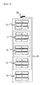
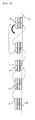
- FIGS. 1 and 2 typically show an exemplary structure and a manufacturing process of a conventional stacked and folded type electrode assembly.
- the separation sheet 20 is disposed between the respective the bicells.
- the separation sheet 20 continuously covers sides of the respective bicells in a state in which the separation sheet 20 is disposed between the respective the bicells.
- the outer end of the separation sheet 20 is fixed by an adhesive tape 25.
- the stacked and folded type electrode assembly may be manufactured, for example, by arranging the bicells 10, 11, 12, 13, and 14 on the separation sheet 20, which has a predetermined length, at predetermined intervals and sequentially winding the separation sheet 20 from one end 21 thereof.
- the bicells 10, 11, 12, 13, and 14 are arranged as follows.
- the first bicell 10 and the second bicell 11 are spaced apart from each other by the width of at least one bicell such that the first bicell 10 and the second bicell 11 are stacked during winding of the separation sheet 20.
- a lower end electrode (anode) of the first bicell 10 faces an upper end electrode (cathode) of the second bicell 11 in a state in which the separation sheet 20 is disposed between the lower end electrode (anode) of the first bicell 10 and the upper end electrode (cathode) of the second bicell 11 after the outside of the first bicell 10 is completely covered by the separation sheet 20.
- the bicells 12, 13, and 14 are arranged such that the distances among the bicells 12, 13, and 14 are sequentially increased in the winding direction of the separation sheet 20.
- the first bicell 10 is an A type bicell configured to have a structure including an anode, a separator, a cathode, a separator, and an anode
- the second bicell 11 and the third bicell 12 each are a C type bicell configured to have a structure including a cathode, a separator, an anode, a separator, and a cathode
- the fourth bicell 13 and the fifth bicell 14 each are an A type bicell configured to have a structure including an anode, a separator, a cathode, a separator, and an anode.
- the capacity of a battery is directly proportional to a loading level. Consequently, the increase of the loading level accompanies the increase of the capacity of the battery. As the loading level is increased, however, the rate capability of the battery is lowered.
- the capacity of the conventional stacked and folded type electrode assembly is increased by increasing the number of bicells having reduced loading levels. That is, it is possible to increase the capacity of a stacked and folded type electrode assembly including 2n-1 bicells A by increasing the number of bicells B each having a lower loading level than each of the bicells A due to limitations of the loading level.
- a stacked and folded type electrode assembly including 2n+1 bicells B is manufactured.
- a capacity to thickness ratio is reduced at a section of the stacked and folded type electrode assembly at which the number of bicells is increased from 2n-1 to 2n+1.
- a stacked and folded type electrode assembly including 2n bicells has a higher capacity to thickness ratio than the conventional stacked and folded type electrode assembly including 2n+1 bicells.
- the electrode assembly according to the unlimited embodiment of the present invention may be configured to have a structure in which 2n bicells, each of which is configured to have a structure in which electrodes, formed by coating a current collector with an electrode mixture, and separators are stacked in a state in which the separators are disposed between the respective electrodes and the uppermost electrode and the lowermost electrode have the same polarity, are stacked.
- a separation sheet is disposed between the respective the bicells. The separation sheet continuously covers sides of the respective bicells at which electrode terminals of the bicells are not formed. Any one selected from between the uppermost bicell and the lowermost bicell may include a single-side coated electrode, formed by coating only one side of the current collector with the electrode mixture, as the outermost electrode.
- the electrode may be a cathode or an anode.
- the cathode may be configured to have a structure in which opposite sides of a cathode current collector are coated with a cathode material or a structure in which only one side of a cathode current collector are coated with a cathode material.
- the anode may be configured to have a structure in which opposite sides of an anode current collector are coated with an anode material. Consequently, any one selected from between the uppermost bicell and the lowermost bicell may be a C type bicell configured to have a structure in which the polarity of the outermost electrode is positive.
- the bicell may be a first electrode element configured to have a structure in which a cathode, an anode, and a separator are simply stacked or a second electrode element configured to have a structure in which a cathode, an anode, and a separator are simply stacked and then laminated.
- the bicell may be configured to have a structure in which second electrode elements, each of which is configured to have a structure in which a cathode, an anode, and a separator are simply stacked and then laminated, are stacked, a structure in which a second electrode element, which is configured to have a structure in which a cathode, an anode, and a separator are simply stacked and then laminated, and a cathode or an anode are simply stacked, or a structure in which a second electrode element, which is configured to have a structure in which a cathode, an anode, and a separator are simply stacked and then laminated, and a cathode or an anode are simply stacked and then laminated.
- the second electrode element In a case in which the second electrode element is included, it is possible to improve mass productivity or yield percent as compared with the first electrode element, which is configured to have a structure in which the cathode, the anode, and the separator are simply stacked. In addition, it is possible to minimize volume expansion of the battery due to swelling, thereby improving safety of the battery.
- the bicell may be an A type bicell configured to have a structure in which a cathode, separators, and anodes are stacked or stacked and then laminated such that the anodes are located at the outermost sides of the bicell or a C type bicell configured to have a structure in which cathodes, separators, and an anode are stacked or stacked and then laminated such that the cathodes are located at the outermost sides of the bicell.
- the bicell may be a combination of a second electrode element configured to have a structure in which a cathode, a separator, and an anode are stacked and then laminated such that the separator is disposed between the cathode and the anode and the cathode and the anode are located at the lowermost sides thereof and a third electrode element configured to have a structure in which any one selected from between a cathode and an anode and a separator are stacked and laminated, a combination of a second electrode element configured to have a structure in which a cathode, an anode, and a separator are stacked and then laminated such that any one selected from between the cathode and the anode and the separator are located at the lowermost sides thereof and a cathode or an anode, or a combination of a second electrode element configured to have a structure in which a cathode, separators, and an anode are stacked and then laminated such that the separat
- the large-area one of the electrodes facing each other in a state in which the separator or the separation sheet is disposed between the electrodes may be configured as an anode. In this case, it is possible to maximally restrain dendritic growth of lithium metal at the anode during charge and discharge of the battery.
- the separation sheet may have a sufficient length to cover sides of the respective bicells at which electrode terminals of the bicells are not formed in a state in which the separation sheet is disposed between the respective bicells.
- the stacked and folded type electrode assembly In the stacked and folded type electrode assembly, tensile force generated during winding or bending of the separation sheet can press the interface between the electrode and the separator or between the electrode and the separation sheet. Consequently, the stacked and folded type electrode assembly is very excellent in terms of battery performance and capacity.
- the separation sheet may have a length extending to cover the electrode assembly once after winding of the separation sheet.
- the outer end of the separation sheet may be fixed by thermal bonding or a tape.
- a thermal welding machine or a hot plate may contact the outer end of the separation sheet after winding of the separation sheet such that the outer end of the separation sheet is melted by heat from the thermal welding machine or the hot plate and fixedly adheres to the other portion of the separation sheet.
- pressure is continuously retained, thereby achieving stable interface contact between the electrode and the separation sheet.
- the separator used in the stacked and folded type electrode assembly preferably has an adhesive function based on thermal bonding so as to configure bicells.
- the separation sheet preferably has such an adhesive function so as to easily perform a winding or bending process.
- the separator and/or the separation sheet may be made of a polymer film for a polymer electrolyte, having an adhesive function by thermal bonding, which includes a first polymer layer of micro porosity and a second polymer layer obtained by gelling polyvinylidene fluoride chlorotrifluoroethylene copolymer, disclosed in Korean Patent Application No. 1999-57312 filed in the name of the applicant of the present application. The disclosure of the application is incorporated herein by reference.
- the cathode and the anode of the lithium secondary battery contact each other with the result that a short circuit occurs.
- the temperature of the lithium secondary battery abruptly increases due to reaction of electrode active materials.
- the lithium secondary battery may catch a fire or explode. That is, the safety of the lithium secondary battery is low.
- the pouch-shaped secondary battery may be easily deformed due to external impact or an external object, such as a needle-shaped body, may easily penetrate the pouch-shaped secondary battery.
- the cathode and the anode of the pouch-shaped secondary battery contact each other with the result that a short circuit occurs.
- the temperature of the pouch-shaped secondary battery abruptly increases due to reaction of electrode active materials.
- a cathode active material made of a lithium transition metal oxide exhibiting low electric conductivity generates a large amount of heat due to high resistance of the cathode active material when a short circuit occurs in the pouch-shaped secondary battery. As a result, combustion or explosion of the pouch-shaped secondary battery is accelerated.
- the outermost bicells function as safety members to prevent penetration of the needle-shaped body such that a minute short circuit occurs primarily in the battery, thereby preventing combustion or explosion of the battery.
- the function of the outermost bicells as the safety member is very important to a middle or large-sized battery module and battery pack configured to have a structure in which combustion or explosion of one lithium secondary battery may lead to combustion or explosion of the entirety of the middle or large-sized battery module and battery pack.
- the bicells may include electrodes configured to have rounded corners so as to prevent the occurrence of a short circuit in the battery due to deformation in shape of the battery when the battery falls in a state in which a corner of the battery is directed downward.
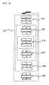
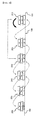
- FIGS. 3 and 4 typically show a structure and a manufacturing process of an electrode assembly according to an unlimited embodiment of the present invention.
- Five bicells 210, 220, 230, 240, and 250 have the same structures as those of the conventional stacked and folded type electrode assembly shown in FIG. 1 .
- the electrode assembly according to the embodiment of the present invention further includes an outermost bicell 260 located at the third place from an A type bicell 210 located at the middle portion of the electrode assembly in a vertical direction with the result that the electrode assembly according to the embodiment of the present invention includes a total of 2n bicells.
- the bicell 260 is configured to have a structure in which a first cathode, a separator, an anode, a separator, and a second cathode are stacked.
- the first cathode and the anode each is formed by coating opposite sides of a current collector with an electrode mixture.
- the second cathode is formed by coating only one side of a current collector with a cathode mixture. Specifically, one side of a current collector facing the A type bicell 210 located at the middle portion of the electrode assembly is coated with a cathode mixture and the other side of the current collector facing the separation sheet is not coated with a cathode mixture.
- the electrode assembly according to the embodiment of the present invention may be manufactured using the method of manufacturing the conventional stacked and folded type electrode assembly.
- the electrode assembly according to the embodiment of the present invention may be manufactured by arranging the bicells 210, 220, 230, 240, and 250 on a long separation sheet 100 at predetermined intervals and sequentially winding the separation sheet 100 from one end 101 thereof.
- the outer end of the separation sheet 100 may be fixed by an adhesive tape.
- FIG. 6 is a typical view showing an electrode assembly according to another embodiment of the present invention.
- the electrode assembly includes an even number of bicells 210, 220, 230, 240, 250, and 260 in the same manner as in the electrode assembly of FIG. 3 except that a separation sheet 100 is folded or bent in the shape of Z.
- the bicell 210 which is one of the outermost bicells 210 and 260, is a C type bicell.
- the C type bicell 210 includes a single-side coated electrode formed by coating only one side of a cathode current collector with a cathode mixture.
- FIGS. 7 to 9 typically show a second electrode element and a third electrode element according to unlimited embodiments of the present invention and a structure in which the electrode elements are stacked, respectively.
- an anode 304, a separator 303, a cathode 302, and a separator 301 are sequentially stacked, laminated, and integrated to form a second electrode element 310.
- an anode 312 and a separator 322 are sequentially stacked, laminated, and integrated to form a third electrode element 320.
- the separator 301 may be removed from the second electrode element 310 to form another second electrode element.
- an additional separator may be stacked and laminated to the lower end of the anode 304 of the second electrode element 310 to form another second electrode element.
- the second electrode element 310 and the third electrode element 320 are sequentially stacked.
- An A type bicell may be manufactured by stacking another second electrode element, formed by removing the separator 301 from the second electrode element 310, on the third electrode element 320.
- the stacked and folded type electrode assembly according to the unlimited embodiment of the present invention has a higher capacity to thickness ratio than the conventional stacked and folded type electrode assembly.
- the stacked and folded type electrode assembly according to the unlimited embodiment of the present invention has a capacity of 1500 mAh at a thickness of 3.9 mm, whereas the conventional stacked and folded type electrode assembly has a capacity of 1450 mAh at the same thickness. Consequently, it can be seen that the capacity of the stacked and folded type electrode assembly including according to the embodiment of the present invention is about 3% greater than that of the conventional stacked and folded type electrode assembly at the same thickness.
- the stacked and folded type electrode assembly according to the embodiment of the present invention is capable of exhibiting safety having the same level as the conventional stacked and folded type electrode assembly.
- Table 2 Nail direction Single-sided cathode Double-sided anode Voltage 4.2 V 4.2 V 4.25 V 4.3 V 4.35 V Present invention 0/5 0/2 0/2 0/2 0/2 Conventional art 0/5 0/2 0/2 0/2 0/2 0/2
- a stacked and folded type electrode assembly according to the present invention includes 2n (n being a natural number equal to or greater than 1) polar bodies which are stacked. Consequently, the present invention has an effect in that the stacked and folded type electrode assembly according to the present invention has a higher capacity to thickness ratio than a conventional stacked and folded type electrode assembly including 2n+1 polar bodies.
- the outermost electrodes are anodes or single-sided cathodes, it is possible to secure safety having the same level as a conventional stacked and folded type electrode assembly including an odd number of polar bodies.
Landscapes
- Chemical & Material Sciences (AREA)
- Engineering & Computer Science (AREA)
- Chemical Kinetics & Catalysis (AREA)
- Electrochemistry (AREA)
- General Chemical & Material Sciences (AREA)
- Manufacturing & Machinery (AREA)
- Materials Engineering (AREA)
- Secondary Cells (AREA)
- Sealing Battery Cases Or Jackets (AREA)
- Cell Separators (AREA)
- Battery Electrode And Active Subsutance (AREA)
Abstract
Description
- The present invention relates to a lithium secondary battery that can be repeatedly charged and discharged and an electrode assembly constituting the same.
- As the price of energy sources has increased due to exhaustion of fossil fuel and concern about environmental pollution has been amplified, the demand for environmentally friendly alternative energy sources has increased as an essential factor for future life. In particular, a recent trend for multiple functions, high performance, and miniaturization of mobile devices has increased the demand for a secondary battery having high capacity while having a small size.
- In terms of the shape of batteries, the demand for prismatic secondary batteries or pouch-shaped secondary batteries, which are thin enough to be applied to products, such as mobile phones, is very high. In terms of the material for batteries, the demand for lithium secondary batteries, such as lithium ion batteries and lithium ion polymer batteries, having high energy density, discharge voltage, and output stability, is very high.
- It is an object of the present invention to provide an electrode assembly having a high capacity to thickness ratio and a lithium secondary battery including the same.
- In accordance with one aspect of the present invention, the above and other objects can be accomplished by the provision of an electrode assembly including 2n (n being a natural number equal to or greater than 1) polar bodies which are stacked.
- The polar bodies may be one or more polar bodies selected from a group consisting of (i) a cathode, (ii) an anode, (iii) a first electrode element including a cathode, an anode, and a first separator, the first electrode element being configured to have a stacked structure in which the cathode and the anode are stacked in a state in which the first separator is separably disposed between the cathode and the anode, (iv) a second electrode element including a cathode, an anode, and a first separator, the second electrode element being configured to have a stacked structure in which the cathode and the anode are stacked in a state in which the first separator is disposed between the cathode and the anode, the cathode, the anode, and the first separator being attached to one another, and (v) a third electrode element including any one selected from between a cathode and an anode and a first separator, any one selected from between the cathode and the anode and the first separator being attached to each other.
- Specifically, the first electrode element may include outermost electrodes having different polarities or the same polarity. In the same manner, the second electrode element may include outermost electrodes having different polarities or the same polarity.
- The second electrode element may be configured to have a structure in which at least one of the outermost electrodes is disposed between first separators. That is, the second electrode element may be configured to have a structure in which one of the outermost electrodes is disposed between the first separators or a structure in which both of the outermost electrodes are disposed between the first separators.
- In addition, the third electrode element may be configured to have a structure in which any one selected from between the cathode and the anode is disposed between the first separators.
- Meanwhile, a second separator may be disposed between the polar bodies. The second separator may include a separation sheet disposed between the polar bodies to cover sides of the polar bodies at which electrode terminals of the polar bodies are not formed.
- On the other hand, at least one selected from between the outermost electrodes may be a single-side coated electrode having an electrode mixture layer formed only at one side of which faces an electrode having an opposite polarity via the first separator.
- The electrode assembly according to the present invention may have a stacked structure of any one selected from among the polar bodies defined in (i) to (v) as described above or a stacked structure of two or more polar bodies selected from among the polar bodies defined in (i) to (v) as described above.
- For example, 2n-1 first electrode elements and any one selected from among the cathode, the anode, and third electrode element may be stacked.
- In addition, 2n-1 second electrode elements and any one selected from among the cathode, the anode, and third electrode element may be stacked.
- In accordance with other aspects of the present invention, there are provided a lithium secondary battery including the electrode assembly with the above-stated construction provided in a battery case together with an electrolyte and a battery module and battery pack including the lithium secondary battery as a unit cell.
- The battery case may be a metal can or a pouch-shaped battery case made of a laminate sheet comprising a metal layer and a resin layer.
- The lithium secondary battery may be a lithium ion polymer battery, a lithium ion battery, or a lithium polymer battery.
- The battery module is configured by connecting a plurality of unit cells in series or in series and parallel. The battery module is well known in the art to which the present invention pertains and, therefore, a detailed description thereof will be omitted.
- In addition, the battery pack including the battery module may be used as a power source of an electric vehicle, a hybrid electric vehicle, a plug-in hybrid electric vehicle, or a power storage device.
- The structure and manufacturing method of a lithium secondary battery and a middle or large-sized battery module and battery pack including the lithium secondary battery as a unit cell are well known in the art to which the present invention pertains and, therefore, a detailed description thereof will be omitted.
- The above and other objects, features and other advantages of the present invention will be more clearly understood from the following detailed description taken in conjunction with the accompanying drawings, in which:
-
FIG. 1 is a typical view showing an exemplary structure of a conventional stacked and folded type electrode assembly; -
FIG. 2 is a typical view exemplarily showing an arrangement combination of polar bodies in a process of manufacturing the stacked and folded type electrode assembly ofFIG. 1 ; -
FIG. 3 is a typical view showing an electrode assembly according to an embodiment of the present invention; -
FIG. 4 is a typical view exemplarily showing an arrangement combination of polar bodies in a process of manufacturing the electrode assembly ofFIG. 3 ; -
FIG. 5 is a graph showing a comparison between a capacity to thickness ratio of the conventional stacked and folded type electrode assembly and a capacity to thickness ratio of the electrode assembly according to the embodiment of the present invention; -
FIG. 6 is a typical view showing an electrode assembly according to another embodiment of the present invention; -
FIG. 7 is a typical view showing a second electrode element according to an embodiment of the present invention; -
FIG. 8 is a typical view showing a third electrode element according to an embodiment of the present invention; and -
FIG. 9 is a view typically showing a structure in which the electrode elements ofFIGS. 7 and 8 are stacked. - Now, exemplary embodiments of the present invention will be described in detail with reference to the accompanying drawings. It should be noted, however, that the scope of the present invention is not limited by the illustrated embodiments.
- In general, a conventional stacked and folded type electrode assembly includes an odd number of bicells. Each bicell is a polar body configured to have a structure in which the uppermost electrode and the lowermost electrode have the same polarity. Each bicell may be a first electrode element or a second electrode element.
-
FIGS. 1 and2 typically show an exemplary structure and a manufacturing process of a conventional stacked and folded type electrode assembly. - Referring to these drawings, five
bicells separation sheet 20 is disposed between the respective bicells such that cathodes and anodes face each other. Theseparation sheet 20 is disposed between the respective the bicells. Theseparation sheet 20 continuously covers sides of the respective bicells in a state in which theseparation sheet 20 is disposed between the respective the bicells. - The outer end of the
separation sheet 20 is fixed by anadhesive tape 25. - The stacked and folded type electrode assembly may be manufactured, for example, by arranging the
bicells separation sheet 20, which has a predetermined length, at predetermined intervals and sequentially winding theseparation sheet 20 from oneend 21 thereof. - At this time, the
bicells first bicell 10 and thesecond bicell 11 are spaced apart from each other by the width of at least one bicell such that thefirst bicell 10 and thesecond bicell 11 are stacked during winding of theseparation sheet 20. During winding of theseparation sheet 20, therefore, a lower end electrode (anode) of thefirst bicell 10 faces an upper end electrode (cathode) of thesecond bicell 11 in a state in which theseparation sheet 20 is disposed between the lower end electrode (anode) of thefirst bicell 10 and the upper end electrode (cathode) of thesecond bicell 11 after the outside of thefirst bicell 10 is completely covered by theseparation sheet 20. - It is necessary to increase the covering length of the
separation sheet 20 such that theother bicells separation sheet 20. To this end, thebicells bicells separation sheet 20. - In addition, it is necessary to configure the
bicells separation sheet 20. To this end, thefirst bicell 10 is an A type bicell configured to have a structure including an anode, a separator, a cathode, a separator, and an anode, thesecond bicell 11 and thethird bicell 12 each are a C type bicell configured to have a structure including a cathode, a separator, an anode, a separator, and a cathode, and thefourth bicell 13 and thefifth bicell 14 each are an A type bicell configured to have a structure including an anode, a separator, a cathode, a separator, and an anode. - The capacity of a battery is directly proportional to a loading level. Consequently, the increase of the loading level accompanies the increase of the capacity of the battery. As the loading level is increased, however, the rate capability of the battery is lowered.
- For this reason, it is necessary to design the loading level in consideration of the rate capability of the battery.
- Due to limitations of the loading level, the capacity of the conventional stacked and folded type electrode assembly is increased by increasing the number of bicells having reduced loading levels. That is, it is possible to increase the capacity of a stacked and folded type electrode assembly including 2n-1 bicells A by increasing the number of bicells B each having a lower loading level than each of the bicells A due to limitations of the loading level.
- As a result, a stacked and folded type electrode assembly including 2n+1 bicells B is manufactured. In this case, however, a capacity to thickness ratio is reduced at a section of the stacked and folded type electrode assembly at which the number of bicells is increased from 2n-1 to 2n+1.
- According to an unlimited embodiment of the present invention, a stacked and folded type electrode assembly including 2n bicells has a higher capacity to thickness ratio than the conventional stacked and folded type electrode assembly including 2n+1 bicells.
- The electrode assembly according to the unlimited embodiment of the present invention may be configured to have a structure in which 2n bicells, each of which is configured to have a structure in which electrodes, formed by coating a current collector with an electrode mixture, and separators are stacked in a state in which the separators are disposed between the respective electrodes and the uppermost electrode and the lowermost electrode have the same polarity, are stacked. A separation sheet is disposed between the respective the bicells. The separation sheet continuously covers sides of the respective bicells at which electrode terminals of the bicells are not formed. Any one selected from between the uppermost bicell and the lowermost bicell may include a single-side coated electrode, formed by coating only one side of the current collector with the electrode mixture, as the outermost electrode.
- The electrode may be a cathode or an anode. The cathode may be configured to have a structure in which opposite sides of a cathode current collector are coated with a cathode material or a structure in which only one side of a cathode current collector are coated with a cathode material. The anode may be configured to have a structure in which opposite sides of an anode current collector are coated with an anode material. Consequently, any one selected from between the uppermost bicell and the lowermost bicell may be a C type bicell configured to have a structure in which the polarity of the outermost electrode is positive.
- The bicell may be a first electrode element configured to have a structure in which a cathode, an anode, and a separator are simply stacked or a second electrode element configured to have a structure in which a cathode, an anode, and a separator are simply stacked and then laminated. In addition, the bicell may be configured to have a structure in which second electrode elements, each of which is configured to have a structure in which a cathode, an anode, and a separator are simply stacked and then laminated, are stacked, a structure in which a second electrode element, which is configured to have a structure in which a cathode, an anode, and a separator are simply stacked and then laminated, and a cathode or an anode are simply stacked, or a structure in which a second electrode element, which is configured to have a structure in which a cathode, an anode, and a separator are simply stacked and then laminated, and a cathode or an anode are simply stacked and then laminated.
- In a case in which the second electrode element is included, it is possible to improve mass productivity or yield percent as compared with the first electrode element, which is configured to have a structure in which the cathode, the anode, and the separator are simply stacked. In addition, it is possible to minimize volume expansion of the battery due to swelling, thereby improving safety of the battery.
- Specifically, the bicell may be an A type bicell configured to have a structure in which a cathode, separators, and anodes are stacked or stacked and then laminated such that the anodes are located at the outermost sides of the bicell or a C type bicell configured to have a structure in which cathodes, separators, and an anode are stacked or stacked and then laminated such that the cathodes are located at the outermost sides of the bicell.
- The bicell may be a combination of a second electrode element configured to have a structure in which a cathode, a separator, and an anode are stacked and then laminated such that the separator is disposed between the cathode and the anode and the cathode and the anode are located at the lowermost sides thereof and a third electrode element configured to have a structure in which any one selected from between a cathode and an anode and a separator are stacked and laminated, a combination of a second electrode element configured to have a structure in which a cathode, an anode, and a separator are stacked and then laminated such that any one selected from between the cathode and the anode and the separator are located at the lowermost sides thereof and a cathode or an anode, or a combination of a second electrode element configured to have a structure in which a cathode, separators, and an anode are stacked and then laminated such that the separators are located at the lowermost sides thereof, another second electrode element configured to have a structure in which a cathode, a separator, and an anode are stacked and then laminated such that the separator is disposed between the cathode and the anode, and a cathode or an anode.
- The large-area one of the electrodes facing each other in a state in which the separator or the separation sheet is disposed between the electrodes may be configured as an anode. In this case, it is possible to maximally restrain dendritic growth of lithium metal at the anode during charge and discharge of the battery.
- The separation sheet may have a sufficient length to cover sides of the respective bicells at which electrode terminals of the bicells are not formed in a state in which the separation sheet is disposed between the respective bicells.
- In a case in which interface contact between the electrode and the separator or between the electrode and the separation sheet is not retained due to repetitive charge and discharge of the battery, the capacity and performance of the lithium secondary battery are abruptly reduced. For this reason, it is necessary to provided pressure that is capable of stably pressing the interface between the electrode and the separator or between the electrode and the separation sheet such that the interface contact between the electrode and the separator or between the electrode and the separation sheet is continuously retained.
- In the stacked and folded type electrode assembly, tensile force generated during winding or bending of the separation sheet can press the interface between the electrode and the separator or between the electrode and the separation sheet. Consequently, the stacked and folded type electrode assembly is very excellent in terms of battery performance and capacity.
- In an unlimited example, the separation sheet may have a length extending to cover the electrode assembly once after winding of the separation sheet.
- The outer end of the separation sheet may be fixed by thermal bonding or a tape.
- For example, a thermal welding machine or a hot plate may contact the outer end of the separation sheet after winding of the separation sheet such that the outer end of the separation sheet is melted by heat from the thermal welding machine or the hot plate and fixedly adheres to the other portion of the separation sheet. As a result, pressure is continuously retained, thereby achieving stable interface contact between the electrode and the separation sheet.
- The separator used in the stacked and folded type electrode assembly preferably has an adhesive function based on thermal bonding so as to configure bicells. On the other hand, it is not necessary for the separation sheet to have such an adhesive function. However, the separation sheet preferably has such an adhesive function so as to easily perform a winding or bending process. In a preferred example, the separator and/or the separation sheet may be made of a polymer film for a polymer electrolyte, having an adhesive function by thermal bonding, which includes a first polymer layer of micro porosity and a second polymer layer obtained by gelling polyvinylidene fluoride chlorotrifluoroethylene copolymer, disclosed in Korean Patent Application No.
1999-57312 - When an external object, such as a needle-shaped body, presses or penetrates the lithium secondary battery, the cathode and the anode of the lithium secondary battery contact each other with the result that a short circuit occurs. At this time, the temperature of the lithium secondary battery abruptly increases due to reaction of electrode active materials. Eventually, the lithium secondary battery may catch a fire or explode. That is, the safety of the lithium secondary battery is low.
- Particularly, in a case in which the stacked and folded type electrode assembly is mounted in a battery case made of a laminate sheet, the mechanical strength of which is relatively low, and the outer edge of the battery case is thermally bonded to manufacture a pouch-shaped secondary battery having a sealed portion, the pouch-shaped secondary battery may be easily deformed due to external impact or an external object, such as a needle-shaped body, may easily penetrate the pouch-shaped secondary battery.
- That is, when an external object, such as a needle-shaped body, presses or penetrates the pouch-shaped secondary battery, the cathode and the anode of the pouch-shaped secondary battery contact each other with the result that a short circuit occurs. At this time, the temperature of the pouch-shaped secondary battery abruptly increases due to reaction of electrode active materials. In addition, a cathode active material made of a lithium transition metal oxide exhibiting low electric conductivity generates a large amount of heat due to high resistance of the cathode active material when a short circuit occurs in the pouch-shaped secondary battery. As a result, combustion or explosion of the pouch-shaped secondary battery is accelerated.
- In the stacked and folded type electrode assembly according to the unlimited embodiment of the present invention, however, the outermost bicells function as safety members to prevent penetration of the needle-shaped body such that a minute short circuit occurs primarily in the battery, thereby preventing combustion or explosion of the battery.
- The function of the outermost bicells as the safety member is very important to a middle or large-sized battery module and battery pack configured to have a structure in which combustion or explosion of one lithium secondary battery may lead to combustion or explosion of the entirety of the middle or large-sized battery module and battery pack.
- More preferably, the bicells may include electrodes configured to have rounded corners so as to prevent the occurrence of a short circuit in the battery due to deformation in shape of the battery when the battery falls in a state in which a corner of the battery is directed downward.
-
FIGS. 3 and4 typically show a structure and a manufacturing process of an electrode assembly according to an unlimited embodiment of the present invention. Fivebicells FIG. 1 . - Unlike the conventional stacked and folded type electrode assembly, however, the electrode assembly according to the embodiment of the present invention further includes an
outermost bicell 260 located at the third place from an Atype bicell 210 located at the middle portion of the electrode assembly in a vertical direction with the result that the electrode assembly according to the embodiment of the present invention includes a total of 2n bicells. - The
bicell 260 is configured to have a structure in which a first cathode, a separator, an anode, a separator, and a second cathode are stacked. The first cathode and the anode each is formed by coating opposite sides of a current collector with an electrode mixture. On the other hand, the second cathode is formed by coating only one side of a current collector with a cathode mixture. Specifically, one side of a current collector facing theA type bicell 210 located at the middle portion of the electrode assembly is coated with a cathode mixture and the other side of the current collector facing the separation sheet is not coated with a cathode mixture. - When a needle-shaped body (not shown) penetrates the electrode assembly, therefore, the metal sheets of the
outermost bicell 260, the amount of heat generated from which due to a short circuit is relatively small, come into contact with each other and short-circuited in the first place, thereby preventing combustion or explosion of the battery. - The electrode assembly according to the embodiment of the present invention may be manufactured using the method of manufacturing the conventional stacked and folded type electrode assembly. For example, the electrode assembly according to the embodiment of the present invention may be manufactured by arranging the
bicells long separation sheet 100 at predetermined intervals and sequentially winding theseparation sheet 100 from oneend 101 thereof. The outer end of theseparation sheet 100 may be fixed by an adhesive tape. -
FIG. 6 is a typical view showing an electrode assembly according to another embodiment of the present invention. Referring toFIG. 6 , the electrode assembly includes an even number ofbicells FIG. 3 except that aseparation sheet 100 is folded or bent in the shape of Z. Thebicell 210, which is one of the outermost bicells 210 and 260, is a C type bicell. The C type bicell 210 includes a single-side coated electrode formed by coating only one side of a cathode current collector with a cathode mixture. -
FIGS. 7 to 9 typically show a second electrode element and a third electrode element according to unlimited embodiments of the present invention and a structure in which the electrode elements are stacked, respectively. - Referring to
FIGS. 7 and 8 , ananode 304, aseparator 303, acathode 302, and aseparator 301 are sequentially stacked, laminated, and integrated to form asecond electrode element 310. In addition, ananode 312 and a separator 322 are sequentially stacked, laminated, and integrated to form athird electrode element 320. Theseparator 301 may be removed from thesecond electrode element 310 to form another second electrode element. In addition, an additional separator may be stacked and laminated to the lower end of theanode 304 of thesecond electrode element 310 to form another second electrode element. - Referring to
FIG. 9 , thesecond electrode element 310 and thethird electrode element 320 are sequentially stacked. An A type bicell may be manufactured by stacking another second electrode element, formed by removing theseparator 301 from thesecond electrode element 310, on thethird electrode element 320. - Energy density of a stacked and folded type electrode assembly including eight stacked bicells according to an embodiment of the present invention and a conventional stacked and folded type electrode assembly including nine stacked bicells was measured and the results are shown in
FIG. 5 . - Referring to
FIG. 5 , it can be seen that the stacked and folded type electrode assembly according to the unlimited embodiment of the present invention has a higher capacity to thickness ratio than the conventional stacked and folded type electrode assembly. - Specifically, the stacked and folded type electrode assembly according to the unlimited embodiment of the present invention has a capacity of 1500 mAh at a thickness of 3.9 mm, whereas the conventional stacked and folded type electrode assembly has a capacity of 1450 mAh at the same thickness. Consequently, it can be seen that the capacity of the stacked and folded type electrode assembly including according to the embodiment of the present invention is about 3% greater than that of the conventional stacked and folded type electrode assembly at the same thickness.
- Safety of the stacked and folded type electrode assembly including the eight stacked bicells according to the unlimited embodiment of the present invention was measured and the results are shown in Table 1 below.
<Table 1> Item Specification Fail/Test Overcharge No fire/No explosion 0/3 Impact No fire/No explosion 0/3 Hot box No fire/No explosion 0/3 Side crush No fire/No explosion 0/3 - Needle penetration experiments were carried out for the stacked and folded type electrode assembly including the eight stacked bicells according to the unlimited embodiment of the present invention and the conventional stacked and folded type electrode assembly including the nine stacked bicells and the results are shown in Table 2 below. As can be seen from the experimental results, the stacked and folded type electrode assembly according to the embodiment of the present invention is capable of exhibiting safety having the same level as the conventional stacked and folded type electrode assembly.
<Table 2> Nail direction Single-sided cathode Double-sided anode Voltage 4.2 V 4.2 V 4.25 V 4.3 V 4.35 V Present invention 0/5 0/2 0/2 0/2 0/2 Conventional art 0/5 0/2 0/2 0/2 0/2 - Although the exemplary embodiments of the present invention have been disclosed for illustrative purposes, those skilled in the art will appreciate that various modifications, additions and substitutions are possible, without departing from the scope and spirit of the invention as disclosed in the accompanying claims.
- As is apparent from the above description, a stacked and folded type electrode assembly according to the present invention includes 2n (n being a natural number equal to or greater than 1) polar bodies which are stacked. Consequently, the present invention has an effect in that the stacked and folded type electrode assembly according to the present invention has a higher capacity to thickness ratio than a conventional stacked and folded type electrode assembly including 2n+1 polar bodies.
- In addition, in a case in which the outermost electrodes are anodes or single-sided cathodes, it is possible to secure safety having the same level as a conventional stacked and folded type electrode assembly including an odd number of polar bodies.
Claims (20)
- An electrode assembly comprising 2n (n being a natural number equal to or greater than 1) polar bodies which are stacked.
- The electrode assembly according to claim 1, wherein the polar bodies are one or more polar bodies selected from a group consisting of (i) a cathode, (ii) an anode, (iii) a first electrode element comprising a cathode, an anode, and a first separator, the first electrode element being configured to have a stacked structure in which the cathode and the anode are stacked in a state in which the first separator is separably disposed between the cathode and the anode, (iv) a second electrode element comprising a cathode, an anode, and a first separator, the second electrode element being configured to have a stacked structure in which the cathode and the anode are stacked in a state in which the first separator is disposed between the cathode and the anode, the cathode, the anode, and the first separator being attached to one another, and (v) a third electrode element comprising any one selected from between a cathode and an anode and a first separator, any one selected from between the cathode and the anode and the first separator being attached to each other.
- The electrode assembly according to claim 2, wherein the first electrode element comprises outermost electrodes having different polarities.
- The electrode assembly according to claim 2, wherein the first electrode element comprises outermost electrodes having the same polarity.
- The electrode assembly according to claim 2, wherein the second electrode element comprises outermost electrodes having different polarities.
- The electrode assembly according to claim 5, wherein the second electrode element is configured to have a structure in which at least one of the outermost electrodes is disposed between first separators.
- The electrode assembly according to claim 2, wherein the second electrode element comprises outermost electrodes having the same polarity.
- The electrode assembly according to claim 7, wherein the second electrode element is configured to have a structure in which at least one of the outermost electrodes is disposed between first separators.
- The electrode assembly according to claim 2, wherein the third electrode element is configured to have a structure in which any one selected from between the cathode and the anode is disposed between first separators.
- The electrode assembly according to claim 1, wherein a second separator is disposed between the polar bodies.
- The electrode assembly according to claim 10, wherein the second separator comprises a separation sheet disposed between the polar bodies to cover sides of the polar bodies at which electrode terminals of the polar bodies are not formed.
- The electrode assembly according to claim 1, wherein at least one selected from between outermost electrodes is a single-side coated electrode having an electrode mixture layer formed only at one side of which faces an electrode having an opposite polarity via the first separator.
- The electrode assembly according to claim 2, wherein 2n-1 first electrode elements and any one selected from among the cathode, the anode, and third electrode element are stacked.
- The electrode assembly according to claim 2, wherein 2n-1 second electrode elements and any one selected from among the cathode, the anode, and third electrode element are stacked.
- A lithium secondary battery comprising an electrode assembly according to any one of claims 1 to 14 provided in a battery case together with an electrolyte.
- The lithium secondary battery according to claim 15, wherein the battery case is a metal can or a pouch-shaped battery case made of a laminate sheet comprising a metal layer and a resin layer.
- The lithium secondary battery according to claim 15, wherein the lithium secondary battery is a lithium ion polymer battery, a lithium ion battery, or a lithium polymer battery.
- A battery module comprising a lithium secondary battery according to claim 15 as a unit cell.
- A battery pack comprising a battery module according to claim 18 as a power source of a device.
- The battery pack according to claim 19, wherein the device is an electric vehicle, a hybrid electric vehicle, a plug-in hybrid electric vehicle, or a power storage device.
Applications Claiming Priority (2)
| Application Number | Priority Date | Filing Date | Title |
|---|---|---|---|
| KR20120047822 | 2012-05-07 | ||
| PCT/KR2013/003985 WO2013168982A1 (en) | 2012-05-07 | 2013-05-07 | Electrode laminate and lithium secondary battery including same |
Publications (3)
| Publication Number | Publication Date |
|---|---|
| EP2849273A1 true EP2849273A1 (en) | 2015-03-18 |
| EP2849273A4 EP2849273A4 (en) | 2015-12-30 |
| EP2849273B1 EP2849273B1 (en) | 2018-03-14 |
Family
ID=49550953
Family Applications (1)
| Application Number | Title | Priority Date | Filing Date |
|---|---|---|---|
| EP13787232.1A Active EP2849273B1 (en) | 2012-05-07 | 2013-05-07 | Electrode laminate and lithium secondary battery including same |
Country Status (6)
| Country | Link |
|---|---|
| US (1) | US9831520B2 (en) |
| EP (1) | EP2849273B1 (en) |
| JP (1) | JP6027228B2 (en) |
| KR (1) | KR101484525B1 (en) |
| CN (1) | CN104247141B (en) |
| WO (1) | WO2013168982A1 (en) |
Families Citing this family (18)
| Publication number | Priority date | Publication date | Assignee | Title |
|---|---|---|---|---|
| US10528590B2 (en) * | 2014-09-26 | 2020-01-07 | Oracle International Corporation | Optimizing a query with extrema function using in-memory data summaries on the storage server |
| CN105794033B (en) * | 2014-01-10 | 2018-09-14 | 株式会社Lg 化学 | With present deep drawing quality matter partition board electrode assembly and include the secondary cell of the electrode assembly |
| KR101671393B1 (en) * | 2014-01-13 | 2016-11-01 | 주식회사 엘지화학 | Battery Cell Comprising Unit Cells Having Different Electrode Structures |
| KR101692772B1 (en) * | 2014-05-15 | 2017-01-04 | 주식회사 엘지화학 | Battery Cell Comprising Tetra Cell |
| KR101713082B1 (en) * | 2014-05-15 | 2017-03-07 | 주식회사 엘지화학 | Battery Cell Comprising Unit Cells Having Different Electrode Structures |
| KR101692776B1 (en) * | 2014-05-15 | 2017-01-17 | 주식회사 엘지화학 | Battery Cell Comprising Tetra cell |
| KR101725921B1 (en) * | 2014-08-11 | 2017-04-11 | 주식회사 엘지화학 | Battery Cell Comprising Unit Cell Stacks and Intermediate Stack Cell |
| CN108886157B (en) * | 2016-04-01 | 2022-05-31 | Ns株式会社 | Electrode assembly manufacturing apparatus and method, and electrode assembly manufactured using the same |
| KR102700153B1 (en) | 2016-05-02 | 2024-08-27 | 삼성에스디아이 주식회사 | Electrode assembly |
| CN106129482A (en) * | 2016-08-17 | 2016-11-16 | 惠州市豪鹏科技有限公司 | A kind of coiled battery structure, the secondary battery including it and battery module |
| US10622684B2 (en) | 2016-08-31 | 2020-04-14 | GM Global Technology Operations LLC | Vehicle battery and monitoring system |
| KR102068710B1 (en) * | 2016-11-08 | 2020-01-22 | 주식회사 엘지화학 | Electrode assembly and the manufacturing method |
| KR102680157B1 (en) * | 2017-02-09 | 2024-06-28 | 에스케이온 주식회사 | Lithium secondary battery |
| KR102217447B1 (en) * | 2017-07-06 | 2021-02-22 | 주식회사 엘지화학 | Secondary Battery |
| CN109560322A (en) * | 2017-12-29 | 2019-04-02 | 蜂巢能源科技有限公司 | The manufacturing method and electrode tinkertoy module of electrode tinkertoy module |
| KR102831130B1 (en) * | 2021-08-13 | 2025-07-04 | 주식회사 엘지에너지솔루션 | Electrode assembly for secondary battery and method for manufacturing the same |
| KR102839269B1 (en) * | 2022-12-02 | 2025-07-25 | 주식회사 엘지에너지솔루션 | Electrode assembly including surface treated separator, secondary battery including the same, and manufacturing method of the electrode assembly |
| WO2025236390A1 (en) * | 2024-05-11 | 2025-11-20 | 湖北亿纬动力有限公司 | Preparation method for thermal composite stacked cell, and thermal composite stacked cell |
Family Cites Families (38)
| Publication number | Priority date | Publication date | Assignee | Title |
|---|---|---|---|---|
| KR19990057312A (en) | 1997-12-29 | 1999-07-15 | 윤종용 | Camcorder device with security system function and control method |
| JP2000228219A (en) * | 1999-02-05 | 2000-08-15 | Toshiba Battery Co Ltd | Polymer lithium secondary battery |
| KR100515572B1 (en) * | 2000-02-08 | 2005-09-20 | 주식회사 엘지화학 | Stacked electrochemical cell and method for preparing the same |
| KR100515571B1 (en) * | 2000-02-08 | 2005-09-20 | 주식회사 엘지화학 | Stacked electrochemical cell |
| KR100497147B1 (en) * | 2000-02-08 | 2005-06-29 | 주식회사 엘지화학 | Multiply stacked electrochemical cell and method for preparing the same |
| US6461762B1 (en) * | 2000-04-20 | 2002-10-08 | Industrial Technology Research Institute | Rechargeable battery structure having a stacked structure of sequentially folded cells |
| JP3687515B2 (en) * | 2000-10-06 | 2005-08-24 | 日本電気株式会社 | battery |
| KR100406690B1 (en) * | 2001-03-05 | 2003-11-21 | 주식회사 엘지화학 | Electrochemical device using multicomponent composite membrane film |
| KR100558842B1 (en) * | 2001-05-16 | 2006-03-10 | 에스케이씨 주식회사 | Organic Electrolyte and Lithium Battery |
| JP2003109666A (en) * | 2001-07-27 | 2003-04-11 | Nissan Motor Co Ltd | Structure for all solid polymer battery, all solid polymer battery and method for manufacturing the same |
| US6908711B2 (en) * | 2002-04-10 | 2005-06-21 | Pacific Lithium New Zealand Limited | Rechargeable high power electrochemical device |
| KR20040017094A (en) * | 2002-08-20 | 2004-02-26 | 삼성에스디아이 주식회사 | Pouch type secondary battery with safty vent |
| JP4305111B2 (en) * | 2003-09-29 | 2009-07-29 | 新神戸電機株式会社 | Battery pack and electric vehicle |
| JP5010250B2 (en) * | 2005-11-28 | 2012-08-29 | Necエナジーデバイス株式会社 | Battery stack and battery pack |
| KR100925857B1 (en) * | 2006-03-14 | 2009-11-06 | 주식회사 엘지화학 | Multiple nested electrochemical cells with increased safety |
| KR100861705B1 (en) * | 2006-05-29 | 2008-10-06 | 주식회사 엘지화학 | Electrode assembly having excellent structural stability and wettability of electrolyte and secondary battery comprising the same |
| KR100873308B1 (en) * | 2006-06-05 | 2008-12-12 | 주식회사 엘지화학 | High Capacity Battery Cell Employed with Two or More Unit Cells |
| KR100882489B1 (en) * | 2006-07-10 | 2009-02-06 | 주식회사 엘지화학 | Stacked / foldable electrode assembly that prevents internal short circuit due to heat shrink and electrochemical cell comprising the same |
| KR100966024B1 (en) * | 2007-04-24 | 2010-06-24 | 주식회사 엘지화학 | Electrochemical device with heterogeneous separator |
| JP5157244B2 (en) * | 2007-05-11 | 2013-03-06 | Tdk株式会社 | Electrochemical device and manufacturing method thereof |
| KR100987300B1 (en) * | 2007-07-04 | 2010-10-12 | 주식회사 엘지화학 | Stack-Folded Electrode Assembly and Method of Manufacturing the Same |
| JP5266748B2 (en) * | 2007-12-21 | 2013-08-21 | マツダ株式会社 | Battery pack |
| JP2010020921A (en) * | 2008-07-08 | 2010-01-28 | Fdk Corp | Power storage cell, and power storage cell module |
| JP4649502B2 (en) * | 2008-08-08 | 2011-03-09 | シャープ株式会社 | Lithium ion secondary battery |
| JP5428296B2 (en) * | 2008-11-04 | 2014-02-26 | コニカミノルタ株式会社 | SECONDARY BATTERY, MANUFACTURING METHOD THEREOF, AND LAMINATED SECONDARY BATTERY |
| KR101155808B1 (en) * | 2009-02-04 | 2012-06-12 | 도요타지도샤가부시키가이샤 | All-solid-state battery and manufacturing method thereof |
| WO2010114318A2 (en) * | 2009-04-01 | 2010-10-07 | 주식회사 엘지화학 | Battery module having flexibility in design structure of module and medium to large sized battery pack including the same |
| JP5504708B2 (en) | 2009-06-25 | 2014-05-28 | 日産自動車株式会社 | Bipolar secondary battery |
| KR101136205B1 (en) * | 2009-11-02 | 2012-04-17 | 삼성에스디아이 주식회사 | Electrode assembly for secondary battery and secondary battery with the electrode assembly |
| JP2011100623A (en) * | 2009-11-06 | 2011-05-19 | Toyota Motor Corp | Stacked battery |
| KR101084909B1 (en) * | 2009-12-07 | 2011-11-17 | 삼성에스디아이 주식회사 | Electrode assembly block and its manufacturing method, secondary battery and its manufacturing method |
| KR20140025617A (en) * | 2010-04-06 | 2014-03-05 | 엔이씨 도낀 가부시끼가이샤 | Electric storage device |
| JP5541957B2 (en) * | 2010-04-13 | 2014-07-09 | シャープ株式会社 | Multilayer secondary battery |
| CN102986079B (en) * | 2010-07-14 | 2016-09-21 | 株式会社Lg化学 | Device for folding electrode assembly |
| MY157141A (en) | 2010-07-26 | 2016-05-13 | Nissan Motor | Bipolar battery |
| US8785027B2 (en) * | 2011-10-05 | 2014-07-22 | Go-Tech Energy Co., Ltd. | Battery pack having cooling system |
| KR20130106755A (en) * | 2012-03-20 | 2013-09-30 | 주식회사 엘지화학 | Electrode assembly and composite electrode assembly of stair-like structure |
| KR101502763B1 (en) * | 2012-12-27 | 2015-03-23 | 주식회사 엘지화학 | Electrode Assembly of Stair-like Structure |
-
2013
- 2013-05-07 CN CN201380021558.1A patent/CN104247141B/en active Active
- 2013-05-07 KR KR20130051572A patent/KR101484525B1/en active Active
- 2013-05-07 WO PCT/KR2013/003985 patent/WO2013168982A1/en not_active Ceased
- 2013-05-07 JP JP2015508880A patent/JP6027228B2/en active Active
- 2013-05-07 EP EP13787232.1A patent/EP2849273B1/en active Active
-
2014
- 2014-10-09 US US14/510,607 patent/US9831520B2/en active Active
Also Published As
| Publication number | Publication date |
|---|---|
| CN104247141A (en) | 2014-12-24 |
| US20150024245A1 (en) | 2015-01-22 |
| KR20130124922A (en) | 2013-11-15 |
| JP2015518257A (en) | 2015-06-25 |
| CN104247141B (en) | 2018-04-27 |
| WO2013168982A1 (en) | 2013-11-14 |
| EP2849273A4 (en) | 2015-12-30 |
| US9831520B2 (en) | 2017-11-28 |
| EP2849273B1 (en) | 2018-03-14 |
| JP6027228B2 (en) | 2016-11-16 |
| KR101484525B1 (en) | 2015-01-20 |
Similar Documents
| Publication | Publication Date | Title |
|---|---|---|
| US9831520B2 (en) | Electrode assembly and lithium secondary battery comprising the same | |
| US10056577B2 (en) | Battery cell of novel structure | |
| EP2038942B1 (en) | Safety kit for secondary battery | |
| US10026944B2 (en) | Electrode assembly having tab-lead joint portion of minimized resistance difference between electrodes and electrochemical cell containing the same | |
| KR101395017B1 (en) | A Stepwise Electrode Assembly, and Battery Cell, Battery Pack and Device Comprising the Same | |
| US8277966B2 (en) | Double winding-typed electrode assembly | |
| KR101336309B1 (en) | Electrode assembly, battery cell and device comprising the same | |
| EP2940776B1 (en) | Electrode assembly of stepped structure | |
| KR101792572B1 (en) | Battery Cell Having Electrode Coated with Insulating Material | |
| CN101796684B (en) | Stacked and folded electrode assembly and preparation method thereof | |
| US20150086842A1 (en) | Battery pack of irregular structure | |
| KR100919691B1 (en) | Unit cell for a secondary battery having a conductive sheet layer and a lithium ion secondary battery using the same | |
| KR101572832B1 (en) | Stepped Electrode Group Stack | |
| US20190334158A1 (en) | Method for Manufacturing an Electrode Assembly for a Battery Cell and Battery Cell | |
| KR20130131843A (en) | Novel electrode separator assembly for secondary battery and method manufacturing the same | |
| JPH0260068A (en) | Sealed lead-acid battery | |
| US20150024261A1 (en) | Battery Cell for Secondary Batteries |
Legal Events
| Date | Code | Title | Description |
|---|---|---|---|
| PUAI | Public reference made under article 153(3) epc to a published international application that has entered the european phase |
Free format text: ORIGINAL CODE: 0009012 |
|
| 17P | Request for examination filed |
Effective date: 20141020 |
|
| AK | Designated contracting states |
Kind code of ref document: A1 Designated state(s): AL AT BE BG CH CY CZ DE DK EE ES FI FR GB GR HR HU IE IS IT LI LT LU LV MC MK MT NL NO PL PT RO RS SE SI SK SM TR |
|
| AX | Request for extension of the european patent |
Extension state: BA ME |
|
| DAX | Request for extension of the european patent (deleted) | ||
| RA4 | Supplementary search report drawn up and despatched (corrected) |
Effective date: 20151202 |
|
| RIC1 | Information provided on ipc code assigned before grant |
Ipc: H01M 10/04 20060101ALI20151126BHEP Ipc: H01M 10/0583 20100101ALI20151126BHEP Ipc: H01M 10/058 20100101AFI20151126BHEP Ipc: H01M 10/052 20100101ALI20151126BHEP Ipc: H01M 4/13 20100101ALI20151126BHEP Ipc: H01M 10/0525 20100101ALI20151126BHEP |
|
| 17Q | First examination report despatched |
Effective date: 20160926 |
|
| GRAP | Despatch of communication of intention to grant a patent |
Free format text: ORIGINAL CODE: EPIDOSNIGR1 |
|
| INTG | Intention to grant announced |
Effective date: 20171214 |
|
| GRAS | Grant fee paid |
Free format text: ORIGINAL CODE: EPIDOSNIGR3 |
|
| GRAA | (expected) grant |
Free format text: ORIGINAL CODE: 0009210 |
|
| AK | Designated contracting states |
Kind code of ref document: B1 Designated state(s): AL AT BE BG CH CY CZ DE DK EE ES FI FR GB GR HR HU IE IS IT LI LT LU LV MC MK MT NL NO PL PT RO RS SE SI SK SM TR |
|
| REG | Reference to a national code |
Ref country code: GB Ref legal event code: FG4D |
|
| REG | Reference to a national code |
Ref country code: CH Ref legal event code: EP Ref country code: AT Ref legal event code: REF Ref document number: 979702 Country of ref document: AT Kind code of ref document: T Effective date: 20180315 |
|
| REG | Reference to a national code |
Ref country code: IE Ref legal event code: FG4D |
|
| REG | Reference to a national code |
Ref country code: DE Ref legal event code: R096 Ref document number: 602013034449 Country of ref document: DE |
|
| REG | Reference to a national code |
Ref country code: FR Ref legal event code: PLFP Year of fee payment: 6 |
|
| REG | Reference to a national code |
Ref country code: NL Ref legal event code: MP Effective date: 20180314 |
|
| REG | Reference to a national code |
Ref country code: LT Ref legal event code: MG4D |
|
| PG25 | Lapsed in a contracting state [announced via postgrant information from national office to epo] |
Ref country code: NO Free format text: LAPSE BECAUSE OF FAILURE TO SUBMIT A TRANSLATION OF THE DESCRIPTION OR TO PAY THE FEE WITHIN THE PRESCRIBED TIME-LIMIT Effective date: 20180614 Ref country code: FI Free format text: LAPSE BECAUSE OF FAILURE TO SUBMIT A TRANSLATION OF THE DESCRIPTION OR TO PAY THE FEE WITHIN THE PRESCRIBED TIME-LIMIT Effective date: 20180314 Ref country code: HR Free format text: LAPSE BECAUSE OF FAILURE TO SUBMIT A TRANSLATION OF THE DESCRIPTION OR TO PAY THE FEE WITHIN THE PRESCRIBED TIME-LIMIT Effective date: 20180314 Ref country code: LT Free format text: LAPSE BECAUSE OF FAILURE TO SUBMIT A TRANSLATION OF THE DESCRIPTION OR TO PAY THE FEE WITHIN THE PRESCRIBED TIME-LIMIT Effective date: 20180314 Ref country code: CY Free format text: LAPSE BECAUSE OF FAILURE TO SUBMIT A TRANSLATION OF THE DESCRIPTION OR TO PAY THE FEE WITHIN THE PRESCRIBED TIME-LIMIT Effective date: 20180314 |
|
| REG | Reference to a national code |
Ref country code: AT Ref legal event code: MK05 Ref document number: 979702 Country of ref document: AT Kind code of ref document: T Effective date: 20180314 |
|
| PG25 | Lapsed in a contracting state [announced via postgrant information from national office to epo] |
Ref country code: BG Free format text: LAPSE BECAUSE OF FAILURE TO SUBMIT A TRANSLATION OF THE DESCRIPTION OR TO PAY THE FEE WITHIN THE PRESCRIBED TIME-LIMIT Effective date: 20180614 Ref country code: GR Free format text: LAPSE BECAUSE OF FAILURE TO SUBMIT A TRANSLATION OF THE DESCRIPTION OR TO PAY THE FEE WITHIN THE PRESCRIBED TIME-LIMIT Effective date: 20180615 Ref country code: RS Free format text: LAPSE BECAUSE OF FAILURE TO SUBMIT A TRANSLATION OF THE DESCRIPTION OR TO PAY THE FEE WITHIN THE PRESCRIBED TIME-LIMIT Effective date: 20180314 Ref country code: LV Free format text: LAPSE BECAUSE OF FAILURE TO SUBMIT A TRANSLATION OF THE DESCRIPTION OR TO PAY THE FEE WITHIN THE PRESCRIBED TIME-LIMIT Effective date: 20180314 Ref country code: SE Free format text: LAPSE BECAUSE OF FAILURE TO SUBMIT A TRANSLATION OF THE DESCRIPTION OR TO PAY THE FEE WITHIN THE PRESCRIBED TIME-LIMIT Effective date: 20180314 |
|
| RAP2 | Party data changed (patent owner data changed or rights of a patent transferred) |
Owner name: LG CHEM, LTD. |
|
| PG25 | Lapsed in a contracting state [announced via postgrant information from national office to epo] |
Ref country code: NL Free format text: LAPSE BECAUSE OF FAILURE TO SUBMIT A TRANSLATION OF THE DESCRIPTION OR TO PAY THE FEE WITHIN THE PRESCRIBED TIME-LIMIT Effective date: 20180314 Ref country code: PL Free format text: LAPSE BECAUSE OF FAILURE TO SUBMIT A TRANSLATION OF THE DESCRIPTION OR TO PAY THE FEE WITHIN THE PRESCRIBED TIME-LIMIT Effective date: 20180314 Ref country code: EE Free format text: LAPSE BECAUSE OF FAILURE TO SUBMIT A TRANSLATION OF THE DESCRIPTION OR TO PAY THE FEE WITHIN THE PRESCRIBED TIME-LIMIT Effective date: 20180314 Ref country code: IT Free format text: LAPSE BECAUSE OF FAILURE TO SUBMIT A TRANSLATION OF THE DESCRIPTION OR TO PAY THE FEE WITHIN THE PRESCRIBED TIME-LIMIT Effective date: 20180314 Ref country code: RO Free format text: LAPSE BECAUSE OF FAILURE TO SUBMIT A TRANSLATION OF THE DESCRIPTION OR TO PAY THE FEE WITHIN THE PRESCRIBED TIME-LIMIT Effective date: 20180314 Ref country code: ES Free format text: LAPSE BECAUSE OF FAILURE TO SUBMIT A TRANSLATION OF THE DESCRIPTION OR TO PAY THE FEE WITHIN THE PRESCRIBED TIME-LIMIT Effective date: 20180314 Ref country code: AL Free format text: LAPSE BECAUSE OF FAILURE TO SUBMIT A TRANSLATION OF THE DESCRIPTION OR TO PAY THE FEE WITHIN THE PRESCRIBED TIME-LIMIT Effective date: 20180314 |
|
| PG25 | Lapsed in a contracting state [announced via postgrant information from national office to epo] |
Ref country code: CZ Free format text: LAPSE BECAUSE OF FAILURE TO SUBMIT A TRANSLATION OF THE DESCRIPTION OR TO PAY THE FEE WITHIN THE PRESCRIBED TIME-LIMIT Effective date: 20180314 Ref country code: SK Free format text: LAPSE BECAUSE OF FAILURE TO SUBMIT A TRANSLATION OF THE DESCRIPTION OR TO PAY THE FEE WITHIN THE PRESCRIBED TIME-LIMIT Effective date: 20180314 Ref country code: SM Free format text: LAPSE BECAUSE OF FAILURE TO SUBMIT A TRANSLATION OF THE DESCRIPTION OR TO PAY THE FEE WITHIN THE PRESCRIBED TIME-LIMIT Effective date: 20180314 Ref country code: AT Free format text: LAPSE BECAUSE OF FAILURE TO SUBMIT A TRANSLATION OF THE DESCRIPTION OR TO PAY THE FEE WITHIN THE PRESCRIBED TIME-LIMIT Effective date: 20180314 |
|
| REG | Reference to a national code |
Ref country code: CH Ref legal event code: PL |
|
| REG | Reference to a national code |
Ref country code: DE Ref legal event code: R097 Ref document number: 602013034449 Country of ref document: DE |
|
| PG25 | Lapsed in a contracting state [announced via postgrant information from national office to epo] |
Ref country code: PT Free format text: LAPSE BECAUSE OF FAILURE TO SUBMIT A TRANSLATION OF THE DESCRIPTION OR TO PAY THE FEE WITHIN THE PRESCRIBED TIME-LIMIT Effective date: 20180716 |
|
| PLBE | No opposition filed within time limit |
Free format text: ORIGINAL CODE: 0009261 |
|
| STAA | Information on the status of an ep patent application or granted ep patent |
Free format text: STATUS: NO OPPOSITION FILED WITHIN TIME LIMIT |
|
| REG | Reference to a national code |
Ref country code: BE Ref legal event code: MM Effective date: 20180531 |
|
| PG25 | Lapsed in a contracting state [announced via postgrant information from national office to epo] |
Ref country code: MC Free format text: LAPSE BECAUSE OF FAILURE TO SUBMIT A TRANSLATION OF THE DESCRIPTION OR TO PAY THE FEE WITHIN THE PRESCRIBED TIME-LIMIT Effective date: 20180314 Ref country code: DK Free format text: LAPSE BECAUSE OF FAILURE TO SUBMIT A TRANSLATION OF THE DESCRIPTION OR TO PAY THE FEE WITHIN THE PRESCRIBED TIME-LIMIT Effective date: 20180314 |
|
| 26N | No opposition filed |
Effective date: 20181217 |
|
| REG | Reference to a national code |
Ref country code: IE Ref legal event code: MM4A |
|
| PG25 | Lapsed in a contracting state [announced via postgrant information from national office to epo] |
Ref country code: LI Free format text: LAPSE BECAUSE OF NON-PAYMENT OF DUE FEES Effective date: 20180531 Ref country code: SI Free format text: LAPSE BECAUSE OF FAILURE TO SUBMIT A TRANSLATION OF THE DESCRIPTION OR TO PAY THE FEE WITHIN THE PRESCRIBED TIME-LIMIT Effective date: 20180314 Ref country code: CH Free format text: LAPSE BECAUSE OF NON-PAYMENT OF DUE FEES Effective date: 20180531 |
|
| PG25 | Lapsed in a contracting state [announced via postgrant information from national office to epo] |
Ref country code: LU Free format text: LAPSE BECAUSE OF NON-PAYMENT OF DUE FEES Effective date: 20180507 |
|
| PG25 | Lapsed in a contracting state [announced via postgrant information from national office to epo] |
Ref country code: IE Free format text: LAPSE BECAUSE OF NON-PAYMENT OF DUE FEES Effective date: 20180507 |
|
| PG25 | Lapsed in a contracting state [announced via postgrant information from national office to epo] |
Ref country code: BE Free format text: LAPSE BECAUSE OF NON-PAYMENT OF DUE FEES Effective date: 20180531 |
|
| PG25 | Lapsed in a contracting state [announced via postgrant information from national office to epo] |
Ref country code: MT Free format text: LAPSE BECAUSE OF NON-PAYMENT OF DUE FEES Effective date: 20180507 |
|
| PG25 | Lapsed in a contracting state [announced via postgrant information from national office to epo] |
Ref country code: TR Free format text: LAPSE BECAUSE OF FAILURE TO SUBMIT A TRANSLATION OF THE DESCRIPTION OR TO PAY THE FEE WITHIN THE PRESCRIBED TIME-LIMIT Effective date: 20180314 |
|
| PG25 | Lapsed in a contracting state [announced via postgrant information from national office to epo] |
Ref country code: HU Free format text: LAPSE BECAUSE OF FAILURE TO SUBMIT A TRANSLATION OF THE DESCRIPTION OR TO PAY THE FEE WITHIN THE PRESCRIBED TIME-LIMIT; INVALID AB INITIO Effective date: 20130507 |
|
| PG25 | Lapsed in a contracting state [announced via postgrant information from national office to epo] |
Ref country code: MK Free format text: LAPSE BECAUSE OF NON-PAYMENT OF DUE FEES Effective date: 20180314 |
|
| PG25 | Lapsed in a contracting state [announced via postgrant information from national office to epo] |
Ref country code: IS Free format text: LAPSE BECAUSE OF FAILURE TO SUBMIT A TRANSLATION OF THE DESCRIPTION OR TO PAY THE FEE WITHIN THE PRESCRIBED TIME-LIMIT Effective date: 20180714 |
|
| P01 | Opt-out of the competence of the unified patent court (upc) registered |
Effective date: 20230408 |
|
| REG | Reference to a national code |
Ref country code: DE Ref legal event code: R081 Ref document number: 602013034449 Country of ref document: DE Owner name: LG ENERGY SOLUTION, LTD., KR Free format text: FORMER OWNER: LG CHEM, LTD., SEOUL, KR |
|
| REG | Reference to a national code |
Ref country code: GB Ref legal event code: 732E Free format text: REGISTERED BETWEEN 20230824 AND 20230831 |
|
| PGFP | Annual fee paid to national office [announced via postgrant information from national office to epo] |
Ref country code: GB Payment date: 20260324 Year of fee payment: 14 |
|
| PGFP | Annual fee paid to national office [announced via postgrant information from national office to epo] |
Ref country code: DE Payment date: 20260420 Year of fee payment: 14 |
|
| PGFP | Annual fee paid to national office [announced via postgrant information from national office to epo] |
Ref country code: FR Payment date: 20260421 Year of fee payment: 14 |