EP2849234A1 - Solar cell apparatus - Google Patents
Solar cell apparatus Download PDFInfo
- Publication number
- EP2849234A1 EP2849234A1 EP20130788590 EP13788590A EP2849234A1 EP 2849234 A1 EP2849234 A1 EP 2849234A1 EP 20130788590 EP20130788590 EP 20130788590 EP 13788590 A EP13788590 A EP 13788590A EP 2849234 A1 EP2849234 A1 EP 2849234A1
- Authority
- EP
- European Patent Office
- Prior art keywords
- solar cell
- lateral rail
- rail member
- photovoltaic system
- frame member
- Prior art date
- Legal status (The legal status is an assumption and is not a legal conclusion. Google has not performed a legal analysis and makes no representation as to the accuracy of the status listed.)
- Withdrawn
Links
- 229910000838 Al alloy Inorganic materials 0.000 claims description 4
- 238000011109 contamination Methods 0.000 abstract description 6
- XLYOFNOQVPJJNP-UHFFFAOYSA-N water Substances O XLYOFNOQVPJJNP-UHFFFAOYSA-N 0.000 description 23
- 239000000758 substrate Substances 0.000 description 14
- 238000010586 diagram Methods 0.000 description 11
- 239000011521 glass Substances 0.000 description 6
- 238000009434 installation Methods 0.000 description 6
- 239000004576 sand Substances 0.000 description 6
- 239000000428 dust Substances 0.000 description 5
- 239000000945 filler Substances 0.000 description 5
- 230000001012 protector Effects 0.000 description 5
- 239000010409 thin film Substances 0.000 description 5
- 238000006243 chemical reaction Methods 0.000 description 4
- 238000010276 construction Methods 0.000 description 4
- 230000000694 effects Effects 0.000 description 4
- 239000000463 material Substances 0.000 description 4
- 238000000034 method Methods 0.000 description 4
- 230000003014 reinforcing effect Effects 0.000 description 4
- 229910021417 amorphous silicon Inorganic materials 0.000 description 3
- -1 CIGS Chemical class 0.000 description 2
- 229910004613 CdTe Inorganic materials 0.000 description 2
- 238000001704 evaporation Methods 0.000 description 2
- 230000008020 evaporation Effects 0.000 description 2
- 238000003780 insertion Methods 0.000 description 2
- 230000037431 insertion Effects 0.000 description 2
- 230000004048 modification Effects 0.000 description 2
- 238000012986 modification Methods 0.000 description 2
- 229910021421 monocrystalline silicon Inorganic materials 0.000 description 2
- 229910021420 polycrystalline silicon Inorganic materials 0.000 description 2
- 229920000139 polyethylene terephthalate Polymers 0.000 description 2
- 239000005020 polyethylene terephthalate Substances 0.000 description 2
- 229920002620 polyvinyl fluoride Polymers 0.000 description 2
- 238000010248 power generation Methods 0.000 description 2
- 239000004065 semiconductor Substances 0.000 description 2
- 150000003376 silicon Chemical class 0.000 description 2
- RYGMFSIKBFXOCR-UHFFFAOYSA-N Copper Chemical compound [Cu] RYGMFSIKBFXOCR-UHFFFAOYSA-N 0.000 description 1
- XAGFODPZIPBFFR-UHFFFAOYSA-N aluminium Chemical compound [Al] XAGFODPZIPBFFR-UHFFFAOYSA-N 0.000 description 1
- 229910052782 aluminium Inorganic materials 0.000 description 1
- 238000007664 blowing Methods 0.000 description 1
- DVRDHUBQLOKMHZ-UHFFFAOYSA-N chalcopyrite Chemical class [S-2].[S-2].[Fe+2].[Cu+2] DVRDHUBQLOKMHZ-UHFFFAOYSA-N 0.000 description 1
- 238000004140 cleaning Methods 0.000 description 1
- 229920001577 copolymer Polymers 0.000 description 1
- 239000011889 copper foil Substances 0.000 description 1
- 229910021419 crystalline silicon Inorganic materials 0.000 description 1
- 230000005611 electricity Effects 0.000 description 1
- 230000002708 enhancing effect Effects 0.000 description 1
- 230000010354 integration Effects 0.000 description 1
- 230000002262 irrigation Effects 0.000 description 1
- 238000003973 irrigation Methods 0.000 description 1
- 230000007774 longterm Effects 0.000 description 1
- 238000000059 patterning Methods 0.000 description 1
- 239000011112 polyethylene naphthalate Substances 0.000 description 1
- 239000011347 resin Substances 0.000 description 1
- 229920005989 resin Polymers 0.000 description 1
- 238000007789 sealing Methods 0.000 description 1
- 229910000679 solder Inorganic materials 0.000 description 1
- 239000010935 stainless steel Substances 0.000 description 1
- 229910001220 stainless steel Inorganic materials 0.000 description 1
- 229920001187 thermosetting polymer Polymers 0.000 description 1
- 239000005341 toughened glass Substances 0.000 description 1
- 229920002554 vinyl polymer Polymers 0.000 description 1
- 238000005406 washing Methods 0.000 description 1
Images








Classifications
-
- H—ELECTRICITY
- H02—GENERATION; CONVERSION OR DISTRIBUTION OF ELECTRIC POWER
- H02S—GENERATION OF ELECTRIC POWER BY CONVERSION OF INFRARED RADIATION, VISIBLE LIGHT OR ULTRAVIOLET LIGHT, e.g. USING PHOTOVOLTAIC [PV] MODULES
- H02S20/00—Supporting structures for PV modules
- H02S20/10—Supporting structures directly fixed to the ground
-
- H—ELECTRICITY
- H02—GENERATION; CONVERSION OR DISTRIBUTION OF ELECTRIC POWER
- H02S—GENERATION OF ELECTRIC POWER BY CONVERSION OF INFRARED RADIATION, VISIBLE LIGHT OR ULTRAVIOLET LIGHT, e.g. USING PHOTOVOLTAIC [PV] MODULES
- H02S20/00—Supporting structures for PV modules
-
- H—ELECTRICITY
- H02—GENERATION; CONVERSION OR DISTRIBUTION OF ELECTRIC POWER
- H02S—GENERATION OF ELECTRIC POWER BY CONVERSION OF INFRARED RADIATION, VISIBLE LIGHT OR ULTRAVIOLET LIGHT, e.g. USING PHOTOVOLTAIC [PV] MODULES
- H02S20/00—Supporting structures for PV modules
- H02S20/20—Supporting structures directly fixed to an immovable object
-
- F—MECHANICAL ENGINEERING; LIGHTING; HEATING; WEAPONS; BLASTING
- F24—HEATING; RANGES; VENTILATING
- F24S—SOLAR HEAT COLLECTORS; SOLAR HEAT SYSTEMS
- F24S20/00—Solar heat collectors specially adapted for particular uses or environments
- F24S2020/10—Solar modules layout; Modular arrangements
- F24S2020/14—Stepped arrangements, e.g. in parallel planes, without module overlapping
-
- F—MECHANICAL ENGINEERING; LIGHTING; HEATING; WEAPONS; BLASTING
- F24—HEATING; RANGES; VENTILATING
- F24S—SOLAR HEAT COLLECTORS; SOLAR HEAT SYSTEMS
- F24S25/00—Arrangement of stationary mountings or supports for solar heat collector modules
- F24S25/10—Arrangement of stationary mountings or supports for solar heat collector modules extending in directions away from a supporting surface
- F24S25/12—Arrangement of stationary mountings or supports for solar heat collector modules extending in directions away from a supporting surface using posts in combination with upper profiles
-
- F—MECHANICAL ENGINEERING; LIGHTING; HEATING; WEAPONS; BLASTING
- F24—HEATING; RANGES; VENTILATING
- F24S—SOLAR HEAT COLLECTORS; SOLAR HEAT SYSTEMS
- F24S25/00—Arrangement of stationary mountings or supports for solar heat collector modules
- F24S25/10—Arrangement of stationary mountings or supports for solar heat collector modules extending in directions away from a supporting surface
- F24S25/16—Arrangement of interconnected standing structures; Standing structures having separate supporting portions for adjacent modules
-
- F—MECHANICAL ENGINEERING; LIGHTING; HEATING; WEAPONS; BLASTING
- F24—HEATING; RANGES; VENTILATING
- F24S—SOLAR HEAT COLLECTORS; SOLAR HEAT SYSTEMS
- F24S25/00—Arrangement of stationary mountings or supports for solar heat collector modules
- F24S25/20—Peripheral frames for modules
-
- F—MECHANICAL ENGINEERING; LIGHTING; HEATING; WEAPONS; BLASTING
- F24—HEATING; RANGES; VENTILATING
- F24S—SOLAR HEAT COLLECTORS; SOLAR HEAT SYSTEMS
- F24S25/00—Arrangement of stationary mountings or supports for solar heat collector modules
- F24S25/30—Arrangement of stationary mountings or supports for solar heat collector modules using elongate rigid mounting elements extending substantially along the supporting surface, e.g. for covering buildings with solar heat collectors
- F24S25/33—Arrangement of stationary mountings or supports for solar heat collector modules using elongate rigid mounting elements extending substantially along the supporting surface, e.g. for covering buildings with solar heat collectors forming substantially planar assemblies, e.g. of coplanar or stacked profiles
- F24S25/35—Arrangement of stationary mountings or supports for solar heat collector modules using elongate rigid mounting elements extending substantially along the supporting surface, e.g. for covering buildings with solar heat collectors forming substantially planar assemblies, e.g. of coplanar or stacked profiles by means of profiles with a cross-section defining separate supporting portions for adjacent modules
-
- F—MECHANICAL ENGINEERING; LIGHTING; HEATING; WEAPONS; BLASTING
- F24—HEATING; RANGES; VENTILATING
- F24S—SOLAR HEAT COLLECTORS; SOLAR HEAT SYSTEMS
- F24S40/00—Safety or protection arrangements of solar heat collectors; Preventing malfunction of solar heat collectors
- F24S40/40—Preventing corrosion; Protecting against dirt or contamination
- F24S40/44—Draining rainwater or condensation
-
- Y—GENERAL TAGGING OF NEW TECHNOLOGICAL DEVELOPMENTS; GENERAL TAGGING OF CROSS-SECTIONAL TECHNOLOGIES SPANNING OVER SEVERAL SECTIONS OF THE IPC; TECHNICAL SUBJECTS COVERED BY FORMER USPC CROSS-REFERENCE ART COLLECTIONS [XRACs] AND DIGESTS
- Y02—TECHNOLOGIES OR APPLICATIONS FOR MITIGATION OR ADAPTATION AGAINST CLIMATE CHANGE
- Y02E—REDUCTION OF GREENHOUSE GAS [GHG] EMISSIONS, RELATED TO ENERGY GENERATION, TRANSMISSION OR DISTRIBUTION
- Y02E10/00—Energy generation through renewable energy sources
- Y02E10/50—Photovoltaic [PV] energy
Definitions
- the present invention relates to a photovoltaic system.
- a photovoltaic system includes a solar cell module and a mount for securing the solar cell module.
- a solar power generation system including a plurality of photovoltaic systems is required to enhance ease of construction of the system and reduce the cost of construction.
- a technique has recently been developed to reduce fastening members for fastening solar cell modules to a mount and fix the solar cell modules to the mount by fitting (refer to PTL 1, for example).
- the mount of the photovoltaic system disclosed in PTL 1 has a structure to hold an upper surface and a lower surface of a frame of each solar cell module. Accordingly, the mount covering the upper surface of the frame of each solar cell module may retain rainwater or the like flowing on the solar cell module in a sloping direction of the solar cell module. Consequently, rainwater tends to accumulate on a light receiving surface of the solar cell module. Furthermore, the light receiving surface of the solar cell module may be contaminated with fine dust or the like contained in rainwater upon evaporation of the rainwater. Therefore, the efficiency of power generation may be reduced.
- a typical large photovoltaic system is designed to be maintenance-free. Accordingly, a light receiving surface (for example, a glass surface) of each solar cell module is not subjected to cleaning.
- Such photovoltaic systems require a technique for reducing the above-described adhesion of dirt.
- One of objects of the present invention is to provide a photovoltaic system with enhanced anti-contamination properties.
- a photovoltaic system comprises a plurality of lateral rail members arranged parallel to one another on a sloping arrangement surface towards from a top to a bottom of the arrangement surface, each lateral rail member including a first rail side portion located on an upper side of the arrangement surface and a second rail side portion located on a lower side of the arrangement surface.
- the apparatus in the present embodiment further includes a solar cell module disposed between a first lateral rail member and a second lateral rail member adjacent to each other of the lateral rail members.
- the first lateral rail member is located on the lower side.
- the second lateral rail member is located on the upper side.
- the solar cell module includes a solar cell panel, a first frame member that is disposed next to the first rail side portion of the first lateral rail member and that protects a first panel side portion of the solar cell panel, and a second frame member that is disposed next to the two rail side portion of the two lateral rail member and that protects a second panel side portion opposite the first panel side portion.
- the level of an upper surface of the first frame member in a vertical direction is equal to or higher than the level of an upper surface of the first lateral rail member in the vertical direction.
- the photovoltaic system exhibits good anti-contamination properties.
- a direction that is parallel to a light receiving surface of a solar cell module 2 included in a photovoltaic system 1 according to an embodiment of the present invention and that is perpendicular to a sloping direction in which the light receiving surface slopes relative to an installation plane P will be referred to as an X-axis direction.
- a direction parallel to the light receiving surface and the sloping direction will be referred to as a Y-axis direction and a direction perpendicular to the light receiving surface will be referred to as a Z-axis direction.
- a lower side of the photovoltaic system 1 in the sloping direction in, for example, Fig. 1 will be referred to as an eaves side and an upper side thereof in the sloping direction in Fig. 1 will be referred to as a ridge side.
- the drawings are for illustration purposes only. The sizes and relative positions of elements in the drawings are not accurately drawn to scale.
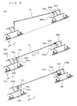
- the photovoltaic system 1 includes pole members 22 on bases 21 arranged on the installation plane P, serving as a horizontal plane, and longitudinal rail members 23 supported by upper parts of the pole members 22 as illustrated in Fig. 1(a) , for example.
- the photovoltaic system 1 further includes a plurality of lateral rail members 24 fixed to the longitudinal rail members 23 such that the lateral rail members 24 are parallel to one another in a direction orthogonal to the longitudinal rail members 23, and one or more solar cell modules 2 arranged between the lateral rail members 24.
- the solar cell module 2 is disposed between a first lateral rail member and a second lateral rail member adjacent to each other.
- the longitudinal rail member 23 has an upper surface corresponding to an arrangement surface on which the lateral rail members 24 are arranged and which slopes relative to the installation plane P.
- the lateral rail members 24 are arranged parallel to one another in a direction from an upper side to a lower side of the sloping arrangement surface.
- the lateral rail member 24 located on the lower side in the sloping direction (-Y direction) is a first lateral rail member and the lateral rail member 24 located on the upper side in the sloping direction (+Y direction) is a second lateral rail member.
- the lateral rail member 24 includes a first rail side portion 24v located on the upper side of the above-described arrangement surface and a second rail side portion 24w located on the lower side of the arrangement surface.
- the solar cell module 2 includes a solar cell panel 15 including a first panel side portion 15v and a first frame member 16v disposed next to the first rail side portion 24v of the above-described first lateral rail member.
- the first frame member 16v protects the first panel side portion 15v of the solar cell panel 15.
- the solar cell module 2 further includes a second frame member 16w disposed next to the second rail side portion 24w of the above-described second lateral rail member (illustrated in Fig. 3 as the same lateral rail member 24 for convenience of description).
- the second frame member 16w protects a second panel side portion 15w (illustrated in Fig. 3 as being included in an eaves-side solar cell panel for convenience of description) opposite the first panel side portion 15v.
- the first frame member 16v includes a fitting portion 16a (for example, a first projection 16e), serving as a first frame engagement portion.
- the fitting portion 16a at a side part of the first frame member 16v, engages with the first rail side portion 24v of the lateral rail member 24, serving as the above-described first lateral rail member.
- a level L of an upper surface of the first frame member 16v in a vertical direction H is equal to or higher than the level of an upper surface of the lateral rail member 24, serving as the first lateral rail member, in the vertical direction.
- the solar cell module 2 includes a cluster of solar cell elements 12 electrically connected to one another.
- the solar cell module 2 can have any of various structures, such as a super-straight structure in which light is incident on a substrate side on which the solar cell elements 12 are arranged, a double glass structure in which the solar cell elements are surrounded with glass substrates, and a substrate structure in which light is incident on the opposite side of the substrate.
- the super-straight structure illustrated in Fig. 2 is suitable for a solar cell including crystalline silicon.
- An exemplary solar cell module having the super-straight structure will be described in the embodiment.
- the solar cell module 2 includes the solar cell panel 15 that is a laminate including a translucent substrate 11, the solar cell elements 12 arranged in predetermined positions relative to the translucent substrate 11, a filler 13 for protecting a surrounding area of the solar cell elements 12, and a rear-surface protector 14.
- the solar cell panel 15 has a light receiving surface 15a that corresponds to a front surface on which light is mainly incident and a rear surface 15b located on a rear side opposite to the light receiving surface 15a.
- the translucent substrate 11 has a function of protecting the solar cell elements 12 and so on from the light receiving surface 15a side.
- the translucent substrate 11 may be comprised of, for example, tempered glass, super white glass or the like.
- the solar cell elements 12 have a function of converting incident light to electricity.
- Each solar cell element 12 includes a semiconductor substrate comprised of, for example, monocrystalline silicon, polycrystalline silicon or the like, and electrodes arranged on a front surface (upper surface) and a rear surface (lower surface) of the semiconductor substrate.
- the solar cell element 12 is, for example, rectangular in plan view. In this case, each side of the solar cell element 12 has a dimension of 100 to 200 mm, for example.
- an electrode disposed on the front surface of one of the two adjacent solar cell elements 12 is electrically connected to an electrode disposed on the rear surface of the other solar cell element 12 by a wiring member (inner lead). Consequently, the solar cell elements 12 are arranged in such a way that these are connected in series.
- the wiring member for example, a solder-coated copper foil and the like can be used.
- any type of solar cell element 12 may be used.
- a thin-film solar cell element comprised of a material such as an amorphous silicon series, chalcopyrite series such as CIGS, CdTe series or the like may be used as a photoelectric conversion portion of the solar cell element.
- the above-described thin-film solar cell element may be configured such that, for example, a photoelectric conversion layer comprised of an amorphous silicon series, CIGS series, CdTe series or the like and transparent electrodes are appropriately laminated on, for example, a glass substrate.
- Such a thin-film solar cell element can be obtained by patterning the photoelectric conversion layer and the transparent electrodes on the glass substrate for integration. Accordingly, a wiring member for connecting the photoelectric conversion layers can be eliminated from the thin-film solar cell element.
- the solar cell element 12 may be of a type in which an amorphous silicon thin film is formed on a monocrystalline or polycrystalline silicon substrate.
- the filler 13, disposed on both principal surfaces of the solar cell element 12, has a function of sealing the solar cell element 12.
- a thermosetting resin such as a copolymer of ethylene-vinyl acetylate, can be used as the filler 13.
- the rear-surface protector 14 has a function of protecting the solar cell elements 12 and the like from a rear side surface 15b side.
- the rear-surface protector 14 is bonded to the filler 13 disposed next to the rear surface 15b of the solar cell panel 15.
- the rear-surface protector 14 may be comprised of, for example, polyvinyl fluoride (PVF), polyethylene terephthalate (PET), polyethylene naphthalate (PEN), or a laminate of layers of materials appropriately selected from those materials.
- an outer edge of the solar cell panel 15 of the solar cell module 2 is provided with frame members 16.
- the frame members 16 have a function of holding the solar cell panel 15.
- Each frame member 16 is an elongated member to strengthen an outer end of the solar cell panel 15.
- the frame member 16 includes a fitting portion 16a, a frame upper surface 16b, a frame bottom face 16c, and a frame side surface 16d.
- the fitting portion 16a is a portion to which the solar cell panel 15 is fitted.
- the frame upper surface 16b is a surface disposed on a sunlight receiving side.
- the frame bottom face 16c is a surface disposed on a back side of the frame upper surface 16b.
- the frame side surface 16d connects the frame upper surface 16b and the frame lower surface 16c and faces outward.
- the frame member 16 corresponding to the lateral rail member 24 includes the first projection 16e on the frame side surface 16d.
- the first projection 16e projects from middle part of the frame member 16 in a direction along the height of the frame member 16 such that the first projection 16e is substantially parallel to the principal surfaces of the solar cell panel 15.
- the first projection 16e is included in the fitting portion (first frame engagement portion) 16a to engage with a first fitting portion 24f, which will be described later, of the lateral rail member 24.
- the above-described frame member 16 can be formed by, for example, extruding aluminum.
- a mount 3 supports the solar cell modules 2. Referring to Fig. 1 , the mount 3 is disposed on the bases 21 arranged on the installation plane P such as the ground.
- the pole members 22 are arranged on ridge-side bases 21a of the bases 21.
- the longitudinal rail member 23 is disposed on an eaves-side base 21b and the pole member 22 so as to span the distance therebetween.
- the lateral rail members 24 are arranged so as to span the distance between the longitudinal rail members 23 provided in parallel with each other. In this case, a longitudinal direction of the lateral rail member 24 is substantially orthogonal to a longitudinal direction of the longitudinal rail member 23.
- the lateral rail members 24 are arranged at regular intervals substantially equal to the width of the solar cell module 2.
- the bases 21 function as foundations of the photovoltaic system 1.
- the bases 21 for example, elongated concrete continuous footings embedded in the ground can be used. If the ground is soft, bottom part of the continuous footing may be widened to reduce ground pressure. Such a continuous footing can be supported by the ground at a relatively large area of the bottom part of the continuous footing. Consequently, a warp in the photovoltaic system 1 caused by uneven settlement of the bases 21 can be reduced. Thus, breakage or the like of the solar cell module 2 is reduced.
- a screw pile which is a type of friction pile made of a stainless steel may be used as the bases 21.
- the screw pile is formed by providing a helical wing on the outer periphery of a pile body which has a circular cross-section. Accordingly, the screw pile exhibits increased surface friction and increased pull-out resistance.
- Such friction piles, serving as the bases 21, enhance pull-out resistance of the photovoltaic system 1 when wind blowing upward applies pressure to the photovoltaic system 1. Thus, the strength of the photovoltaic system 1 is increased.
- the pole members 22 are arranged on the ridge-side first bases 21a and the eaves-side second bases 21b such that a longitudinal direction of the pole members 22 is perpendicular to the installation plane P. Referring to Fig. 1 , the pole member 22 supports a ridge-side part of the longitudinal rail member 23.
- Each pole member 22 has a cross-section shaped like "I” or "H", for example.
- Such a pole member 22 can be formed by, for example, extruding an aluminum alloy.
- the longitudinal rail member 23 is a member disposed on the base 21 and the pole member 22 so as to span the distance therebetween and slope relative to the installation plane P.
- the lateral rail members 24 are fixed on the longitudinal rail members 23 provided in parallel with each other such that the lateral rail members 24 are substantially orthogonal to the longitudinal direction of the longitudinal rail members 23.
- the longitudinal rail members 23 have a cross-section similar to, for example, that of a substantially square pipe.
- Such a longitudinal rail member 23 can be formed by, for example, extruding an aluminum alloy.
- the lateral rail member 24 is disposed on the longitudinal rail members 23 such that the lateral rail member 24 is longitudinally aligned with the X-axis direction.
- the lateral rail member 24 may be an elongated member having an elongated shape, for example.
- a longitudinal dimension (in the X-axis direction) of the lateral rail member 24 may be appropriately determined depending on the dimensions and material of the solar cell module 2. For example, this dimension may be a dimension of one or more solar cell modules 2 in the X-axis direction.
- the longitudinal dimension of the lateral rail member 24 is two times as long as the dimension of the solar cell module 2 in the X-axis direction.
- the lateral rail member 24 has a shape like a square pipe having a closed cross-section and having thereon recesses opening in both directions perpendicular to the longitudinal direction. Accordingly, the lateral rail member 24 includes support portions 24a, a bottom portion 24b, hook-shaped portions 24c, an upper face end 24d, an upper portion 24e, the first fitting portion 24f, and a second fitting portion 24g.
- the support portion 24a is a face that supports the frame bottom face 16c of the solar cell module 2 and extends in the X-axis direction.
- the lateral rail member 24 includes the support portion 24a that abuts against the frame bottom face 16c of the frame member 16, serving as the first frame member, of the solar cell module 2.
- the support portion 24a functions as a guide portion to guide the first frame engagement portion 16a to the first rail side portion 24v of the lateral rail member 24.
- the bottom portion 24b of the lateral rail member 24 is a portion to abut against an upper surface of the longitudinal rail member 23.
- the bottom portion 24b is located under the support portion 24a.
- the hook-shaped portions 24c project from both sides of the bottom portion 24b in the Y-axis direction and each include a hook extending in the Z-axis direction.
- the hook-shaped portions 24c can be coupled to a stopper 25 fastened to the longitudinal rail member 23 by, for example, a bolt and a nut.
- the first fitting portion 24f and the second fitting portion 24g of the lateral rail member 24 open in both directions in the Y-axis direction on the upper side of the support portion 24a.
- the first fitting portion 24f and the second fitting portion 24g are recesses, for example.
- the first projection 16e of the eaves-side frame member 16 of the solar cell module 2 is inserted into the first fitting portion 24f. Consequently, the first projection 16e engages with the first fitting portion 24f.
- the distance of the first fitting portion 24f in the Z-axis direction is substantially equal to the distance in the Z-axis direction between the frame bottom face 16c and an upper surface of the first projection 16e of the frame member 16.
- the first projection 16e When an upper surface of the first fitting portion 24f comes into contact with the upper surface of the first projection 16e, the first projection 16e can be inserted into and engage with (or fit in) the first fitting portion 24f.
- the upper surface of the first fitting portion 24f and the first projection 16e do not have to be in contact with each other. For example, a small clearance may be provided between the upper surface of the first recess 24f and the first projection 16e. This facilitates insertion of the first projection 16e into the first fitting portion 24f.
- the ridge-side frame member 16 of the solar cell module 2 is inserted into the second fitting portion 24g. More specifically, the distance of the second fitting portion 24g in the Z-axis direction is substantially equal to the distance between the frame upper surface 16b and the frame bottom face 16c of the frame member 16, so that the ridge-side frame member 16 of the solar cell module 2 can be inserted into and engage with (or fit in) the second fitting portion 24g.
- the second rail side portion 24w of the lateral rail member 24 covers an upper surface of the second frame member 16w of the solar cell module 2.
- the level L of the upper surface of the first frame member 16v in the vertical direction H is equal to or higher than the level of the upper surface of the lateral rail member 24, serving as the first lateral rail member, in the vertical direction.
- Such a lateral rail member 24 can be formed by, for example, extruding an aluminum alloy.
- the ridge-side frame 16w, serving as the second frame member, of the solar cell module 2 is inserted at an angle into the second fitting portion 24g of a lateral rail member 241, serving as the second lateral rail member, located on an upper side. Then, the frame bottom face 16d of the eaves-side frame 16v, serving as the first frame member, of the solar cell module 2 is moved onto the support portion 24a of a lateral rail member 242, serving as the first lateral rail member.
- the frame bottom face 16d of the solar cell module 2 are set on the support portion 24a of the lateral rail member 241 and the support portion 24a of the lateral rail member 242, serving as the first lateral rail member.
- the solar cell module 2 is shifted toward the eave side in the Y-axis direction so that the ridge-side frame 16w of the solar cell module 2 engages with the second fitting portion 24g of the lateral rail member 241.
- the eaves-side frame 16v serving as the first frame member, engages with the first fitting portion 24f of the lateral rail member 242.
- the stopper 25 may be disposed between the second fitting portion 24g and the eaves-side frame 16w. Consequently, the solar cell module 2 is less likely to disconnect from the lateral rail member 241 if the solar cell module 2 shifts toward the ridge side in the Y-axis direction.
- the solar cell module 2 may be fixed to the lateral rail member 24 with fastening members 27, as illustrated in Fig. 5 .
- the fastening members 27 are arranged in a first support portion 24a1 and a second support portion 24a2 extending from both the sides of the lateral rail member 24 in the Y-axis direction.
- the first and second support portions 24a1 and 24a2 each have a through-hole into which the fastening member 27 is inserted. In this case, as illustrated in Fig.
- the solar cell module 2 further has holes 17 arranged in a third frame member 16x and a fourth frame member 16y connected to the eaves-side frame 16w, serving as the first frame member, and the ridge-side frame 16v, serving as the second frame member. Additionally, if the solar cell module 2 includes a rear-surface reinforcing member 18 as illustrated in Fig. 6 , the rear-surface reinforcing member 18 also has holes 17. The fastening members 27 may be inserted into the holes 17 of the third frame member 16x, the fourth frame member 16y, and the rear-surface reinforcing member 18 to fix the solar cell module 2 to the first and second support portions 24a1 and 24a2 of the lateral rail members 24.
- the level L of the upper surface of the first frame member 16v of the solar cell module 2 in the vertical direction H is equal to or higher than the level of the upper surface of the lateral rail member 24, serving as the first lateral rail member, in the vertical direction.
- the frame upper surface 16b and the upper portion of the lateral rail member 24e can be substantially flush with each other or can provide a step between the frame upper surface 16b at a higher level and the upper portion at a lower level. Consequently, rainwater, dust and the like are less likely to accumulate on the light receiving surface of the solar cell module 2 in the embodiment, thus reducing the amount of dust and the like deposited upon evaporation of rainwater or the like. This enhances the anti-contamination properties.
- the height of the second fitting portion 24g of the lateral rail member 24 in the Z-axis direction may be greater than the height of the frame member 16 of the solar cell module 2 in the Z-axis direction and the depth of the second fitting portion 24g in the Y-axis direction may be slightly greater than the length of the first projection 16e of the frame member 16 in the Y-axis direction.
- This facilitates insertion of the first projection 16e into the second fitting portion 24g while the solar cell module 2 is inclined in the Y direction as illustrated in Fig. 4(a) .
- the solar cell module 2 can be easily arranged in parallel and secured between the lateral rail members 24. Consequently, the ease of construction is improved.
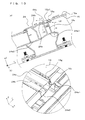
- a photovoltaic system 1 according to a second embodiment of the present invention differs from that according to the first embodiment in the structure of the eaves-side frame member 16 of the solar cell module 2 as illustrated in Figs. 7 and 8 .
- the first frame member 16v has one or more notches 16g in the upper surface thereof.
- the notches 16g are arranged in the frame upper surface 16b and an overhang portion 16f of the frame member 16.
- Each notch 16g has a width of 1 to 2 cm in the X-axis direction.
- the frame member 16 having the notches 16g is disposed in eaves-side part of the solar cell module 2. Consequently, rainwater on the photovoltaic system 1 passes through the notches 16g in the frame upper surface 16b and the overhang portion 16f and flows into the lateral rail member 24. The flow of water is indicated by an arrow 26 in Fig. 9(b) .
- the overhang portion 16f protruding outwardly from the frame side surface is disposed near the fitting portion 16a. Since the notches 16g are arranged, the overhang portion 16f has a structure partially notched. Accordingly, a space is provided under the overhang portion 16f. This space defines a passage for rainwater.
- the notches 16g can be arranged at any positions in the eaves-side frame.
- the notches 16g may be arranged in substantially middle part of the eaves-side frame of the solar cell module. This prevents water from accumulating in the vicinity of central part of the solar cell panel, thus enhancing an anti-contamination effect.
- the notches 16g may be arranged in both end parts of the first frame member 16v in the longitudinal direction of the first frame member 16v. Consequently, an excessive decrease in strength of the first frame member 16v can be reduced and a drainage effect can be maintained.
- the water which has flowed into the lateral rail member 24 smoothly flows along the lateral rail member 24 in the X-axis direction and is then efficiently discharged from an end portion of the lateral rail member 24.
- the anti-contamination properties are further enhanced in the above-described manner.
- a photovoltaic system 1 according to a third embodiment of the present invention differs from that according to the second embodiment in the height of the light receiving surface 15a of the solar cell panel 15 exposed in the notches 16g of the first frame member 16v of the solar cell module 2.
- a level L1 of a light receiving surface 15a1 (upper surface) of the solar cell panel 15 exposed in the notches 16g in the vertical direction is higher than a level L2 of the upper surface of the lateral rail member 24, corresponding to the first rail member, in the vertical direction.
- a height in the Z-axis direction from the first support portion 24a1, which supports the first frame member 16v, of the lateral rail member 24 to the upper portion 24e thereof is less than the height of the first frame member 16v of the solar cell module 2 in the Z-axis direction.
- a height from the second support portion 24a2, which supports the second frame member 16w, of the lateral rail member 24 to the upper portion 24e thereof is substantially the same as the height of a second frame member 162 of the solar cell module 2 in the Z-axis direction.
- the upper surface 24e of the lateral rail member 24 may have a recess 24h opening in the upper surface 24e in the embodiment. Accordingly, rainwater and sand flowing from the light receiving surface 15a of the solar cell panel 15 of the solar cell module 2 disposed on the ridge side tend to accumulate in the recess 24h. Consequently, the rainwater and sand do not tend to flow to the solar cell module 2 disposed on the eave side. Thus, dirt on the solar cell panel 15 of the solar cell module 2 disposed on the eave side is reduced. In addition, rainwater and sand accumulated in the recess 24h flow in the X-axis direction and are then discharged from the sides of the photovoltaic system 1. In this case, the recess 24h may be greater than or equal to a step defined by the light receiving surface 15a of the solar cell panel 15 and the frame upper surface 16b.
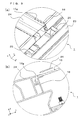
- a photovoltaic system 1 according to a fourth embodiment of the present invention differs from that according to the third embodiment in that the longitudinal rail member 23 has a recess 23a in the upper surface thereof as illustrated in Figs. 11 and 12 .
- the recess 24h of the lateral rail member 24 extends to a first end 24A of the lateral rail member 24 as illustrated in Fig. 12 .
- at least one of the above-described first and second lateral rail members 242 and 241 may have this structure.
- the longitudinal rail member 23 is disposed under the first end 24A of the lateral rail member 24 (in a -Z direction).
- the lateral rail member 24h may be disposed such that the level of a second end 24B of the lateral rail member 24h is higher than that of the first end 24A thereof in the vertical direction (+Z direction). Consequently, if a small amount of water accumulates in the recess 24h of the lateral rail member 24, the water is easily discharged to the outside.
- Such a configuration can be achieved by, for example, allowing the pole members 22 arranged under the first and second ends 24A and 24B of the lateral rail member 24 to have different lengths.
- the angle of inclination of the lateral rail member 24 may be determined in consideration of a warp in substantially the middle of the lateral rail member 24 caused by the weight of the solar cell array. It is sufficient that the lateral rail member 24 is inclined in one direction at an angle above the horizontal in the warp portion.
- water flowing in the recess 23a of the longitudinal rail member 23 can be collected in a container 29 through a gutter 28 disposed on a lower edge side of the longitudinal rail member 23.
- the rainwater collected in that manner can be used to wash off fine dust on the photovoltaic system 1 and can also be used for irrigation or the like in the surrounding area.
- this configuration is useful because a relatively large amount of water can be efficiently collected.
- the shape of the lateral rail member 24 in the embodiment is not limited to that illustrated in Fig. 10 .
- the lateral rail member 24 may have a shape illustrated in Fig. 13 .
- the lateral rail member 24 includes an abutment portion 24x that is long in the Y-axis direction. Accordingly, the upper face end 24d of the lateral rail member 24 is not contact with the frame upper surface 16b but the abutment portion 24x is in contact with the frame side surface 16d. In such a configuration, a gap portion 30 is defined between the upper face end 24d and the frame upper surface 16b.
- water can be guided into the recess 23a of the longitudinal rail member 23 with the lateral rail member 24 having no recess 24h.
- water tends to accumulate in a corner 24j defined by the support portion 24a and a portion 24i of the lateral rail member 24.
- the water accumulated in the corner 24j flows in the X direction, so that the water can be collected in the recess 23a of the longitudinal rail member 23.
- the water collected in the recess 23a can be drained downward in the - Y direction, for example. This facilitates collection of water in the above-described container 29.
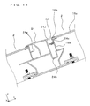
- the lateral rail member 24 positioned closest to the edge of the eaves receives the solar cell module 2 on only the ridge side. Accordingly, the lateral rail member 24 closest to the edge of the eaves may have no second fitting portion 24g that is disposed on the second rail side portion 24w side as illustrated in Fig. 14 .
- the present invention is not limited to the above-described embodiments.
- the details of the embodiments may be changed for suitable use.
- all of the lateral rail members 24 of the photovoltaic system 1 do not necessarily have to have the recess 24h.
- Some of the lateral rail members 24 may have the recess 24h.
- only the lateral rail member 24 closest to the edge of the eaves may have the recess 24h and the other lateral rail members 24 may have no recess 24h in the photovoltaic system 1.
Landscapes
- Photovoltaic Devices (AREA)
- Roof Covering Using Slabs Or Stiff Sheets (AREA)
Abstract
Description
- The present invention relates to a photovoltaic system.
- A photovoltaic system includes a solar cell module and a mount for securing the solar cell module.
- A solar power generation system including a plurality of photovoltaic systems is required to enhance ease of construction of the system and reduce the cost of construction. A technique has recently been developed to reduce fastening members for fastening solar cell modules to a mount and fix the solar cell modules to the mount by fitting (refer to
PTL 1, for example). - PTL 1: Japanese Unexamined Patent Application Publication No.
2011-153465 - The mount of the photovoltaic system disclosed in
PTL 1 has a structure to hold an upper surface and a lower surface of a frame of each solar cell module. Accordingly, the mount covering the upper surface of the frame of each solar cell module may retain rainwater or the like flowing on the solar cell module in a sloping direction of the solar cell module. Consequently, rainwater tends to accumulate on a light receiving surface of the solar cell module. Furthermore, the light receiving surface of the solar cell module may be contaminated with fine dust or the like contained in rainwater upon evaporation of the rainwater. Therefore, the efficiency of power generation may be reduced. - A typical large photovoltaic system is designed to be maintenance-free. Accordingly, a light receiving surface (for example, a glass surface) of each solar cell module is not subjected to cleaning. Such photovoltaic systems require a technique for reducing the above-described adhesion of dirt.
- One of objects of the present invention is to provide a photovoltaic system with enhanced anti-contamination properties.
- A photovoltaic system according to an embodiment of the present invention comprises a plurality of lateral rail members arranged parallel to one another on a sloping arrangement surface towards from a top to a bottom of the arrangement surface, each lateral rail member including a first rail side portion located on an upper side of the arrangement surface and a second rail side portion located on a lower side of the arrangement surface. The apparatus in the present embodiment further includes a solar cell module disposed between a first lateral rail member and a second lateral rail member adjacent to each other of the lateral rail members. The first lateral rail member is located on the lower side. The second lateral rail member is located on the upper side. In the present embodiment, the solar cell module includes a solar cell panel, a first frame member that is disposed next to the first rail side portion of the first lateral rail member and that protects a first panel side portion of the solar cell panel, and a second frame member that is disposed next to the two rail side portion of the two lateral rail member and that protects a second panel side portion opposite the first panel side portion. In the present invention, the level of an upper surface of the first frame member in a vertical direction is equal to or higher than the level of an upper surface of the first lateral rail member in the vertical direction.
- According to the above-described embodiment, the photovoltaic system exhibits good anti-contamination properties.
-
- [
Fig. 1] Fig. 1 is a diagram illustrating a photovoltaic system according to an embodiment of the present invention,Fig. 1(a) being a perspective view of the photovoltaic system,Fig. 1(b) being an enlarged perspective view of part A inFig. 1(a) . - [
Fig. 2] Fig. 2 is a diagram illustrating an exemplary solar cell module used in the photovoltaic system according to the embodiment of the present invention,Fig. 2(a) being a plan view of the solar cell module as viewed from a light receiving surface side,Fig. 2(b) being a cross-sectional view taken along the line B-B' inFig. 2(a) . - [
Fig. 3] Fig. 3 is a diagram illustrating a part of the photovoltaic system according to the embodiment of the present invention,Fig. 3 being a sectional view taken along the line C-C' inFig. 1(a) . - [
Fig. 4] Figs. 4 (a) to (c) are sectional views illustrating exemplary assembling of the photovoltaic system according to the embodiment of the present invention. - [
Fig. 5] Fig. 5 illustrates a modification of the photovoltaic system according to the embodiment of the present invention,Fig. 5 being a sectional view of part corresponding to that ofFig. 3 . - [
Fig. 6] Fig. 6 illustrates an exemplary solar cell module used in the modification of the photovoltaic system according to the embodiment of the present invention,Fig. 6(a) being a plan view of the solar cell module as viewed from a rear surface side,Fig. 6(b) being a cross-sectional view taken along the line D-D' inFig. 6(a), Fig. 6(c) being a sectional view taken along the line E-E' inFig. 6(a) . - [
Fig. 7] Fig. 7 illustrates an exemplary solar cell module used in a photovoltaic system according to another embodiment of the present invention,Fig. 7(a) being a plan view of the solar cell module as viewed from the light receiving surface side,Fig. 7(b) being a sectional view taken along the line F-F' inFig. 7(a), Fig. 7(c) being a sectional view taken along the line G-G' inFig. 7(b) . - [
Fig. 8] Fig. 8 is a diagram illustrating a part of a solar cell module used in the photovoltaic system according to the another embodiment of the present invention,Fig. 8 being an enlarged perspective view of part J inFig. 7(a) . - [
Fig. 9] Fig. 9 is diagrams illustrating parts of the photovoltaic system according to the another embodiment of the present invention,Fig. 9(a) being an enlarged perspective view of part corresponding to part A inFig. 1(b) ,Fig. 9(b) being a sectional view illustrating an exemplary water passage. - [
Fig. 10] Fig. 10 is diagrams illustrating parts of a photovoltaic system according to another embodiment of the present invention,Fig. 10(a) being a sectional view of part corresponding to part taken along the line C-C' inFig. 1(a) ,Fig. 10(b) being an enlarged perspective view of part corresponding to the part A inFig. 1(a) . - [
Fig. 11] Fig. 11 is diagram illustrating a photovoltaic system according to another embodiment of the present invention,Fig. 11(a) being a side view of the photovoltaic system,Fig. 11(b) being a sectional view of the photovoltaic system taken along the line K-K' inFig. 11(a) . - [
Fig. 12] Fig. 12 is a diagram illustrating a part of the photovoltaic system according to the another embodiment of the present invention,Fig. 12 being an enlarged plan view of part M inFig. 11(b) . - [
Fig. 13] Fig. 13 is a diagram illustrating a part of a photovoltaic system according to the another embodiment of the present invention,Fig. 13 being an enlarged plan view of part N inFig. 11(a) . - [
Fig. 14] Fig. 14 is a diagram illustrating a part of a photovoltaic system according to the another embodiment of the present invention,Fig. 14 being an enlarged plan view of the part N inFig. 11(a) . - [
Fig. 15] Fig. 15 is a diagram illustrating a part of a photovoltaic system according to the another embodiment of the present invention,Fig. 15 being an enlarged sectional view of part in the vicinity of a lateral rail member closest to eaves. - Photovoltaic systems according to embodiments of the present invention will be described with reference to the drawings. In the following description, a direction that is parallel to a light receiving surface of a
solar cell module 2 included in aphotovoltaic system 1 according to an embodiment of the present invention and that is perpendicular to a sloping direction in which the light receiving surface slopes relative to an installation plane P will be referred to as an X-axis direction. In addition, a direction parallel to the light receiving surface and the sloping direction will be referred to as a Y-axis direction and a direction perpendicular to the light receiving surface will be referred to as a Z-axis direction. In the following description, a lower side of thephotovoltaic system 1 in the sloping direction in, for example,Fig. 1 will be referred to as an eaves side and an upper side thereof in the sloping direction inFig. 1 will be referred to as a ridge side. The drawings are for illustration purposes only. The sizes and relative positions of elements in the drawings are not accurately drawn to scale. - The
photovoltaic system 1 includespole members 22 onbases 21 arranged on the installation plane P, serving as a horizontal plane, andlongitudinal rail members 23 supported by upper parts of thepole members 22 as illustrated inFig. 1(a) , for example. Thephotovoltaic system 1 further includes a plurality oflateral rail members 24 fixed to thelongitudinal rail members 23 such that thelateral rail members 24 are parallel to one another in a direction orthogonal to thelongitudinal rail members 23, and one or moresolar cell modules 2 arranged between thelateral rail members 24. Thesolar cell module 2 is disposed between a first lateral rail member and a second lateral rail member adjacent to each other. - The
longitudinal rail member 23 has an upper surface corresponding to an arrangement surface on which thelateral rail members 24 are arranged and which slopes relative to the installation plane P. Thelateral rail members 24 are arranged parallel to one another in a direction from an upper side to a lower side of the sloping arrangement surface. In this embodiment, accordingly, thelateral rail member 24 located on the lower side in the sloping direction (-Y direction) is a first lateral rail member and thelateral rail member 24 located on the upper side in the sloping direction (+Y direction) is a second lateral rail member. As illustrated inFig. 1(b) , thelateral rail member 24 includes a firstrail side portion 24v located on the upper side of the above-described arrangement surface and a secondrail side portion 24w located on the lower side of the arrangement surface. - As illustrated in
Figs. 2 and3 , thesolar cell module 2 includes asolar cell panel 15 including a firstpanel side portion 15v and afirst frame member 16v disposed next to the firstrail side portion 24v of the above-described first lateral rail member. Thefirst frame member 16v protects the firstpanel side portion 15v of thesolar cell panel 15. Thesolar cell module 2 further includes asecond frame member 16w disposed next to the secondrail side portion 24w of the above-described second lateral rail member (illustrated inFig. 3 as the samelateral rail member 24 for convenience of description). Thesecond frame member 16w protects a secondpanel side portion 15w (illustrated inFig. 3 as being included in an eaves-side solar cell panel for convenience of description) opposite the firstpanel side portion 15v. - Referring to
Fig. 2 , thefirst frame member 16v includes afitting portion 16a (for example, afirst projection 16e), serving as a first frame engagement portion. Thefitting portion 16a, at a side part of thefirst frame member 16v, engages with the firstrail side portion 24v of thelateral rail member 24, serving as the above-described first lateral rail member. A level L of an upper surface of thefirst frame member 16v in a vertical direction H is equal to or higher than the level of an upper surface of thelateral rail member 24, serving as the first lateral rail member, in the vertical direction. - Exemplary components of the
photovoltaic system 1 illustrated inFig. 1 will now be described in detail. - As illustrated in
Fig. 2(a) and (b) , thesolar cell module 2 includes a cluster ofsolar cell elements 12 electrically connected to one another. Thesolar cell module 2 can have any of various structures, such as a super-straight structure in which light is incident on a substrate side on which thesolar cell elements 12 are arranged, a double glass structure in which the solar cell elements are surrounded with glass substrates, and a substrate structure in which light is incident on the opposite side of the substrate. In particular, the super-straight structure illustrated inFig. 2 is suitable for a solar cell including crystalline silicon. An exemplary solar cell module having the super-straight structure will be described in the embodiment. - As illustrated in
Fig. 2 , thesolar cell module 2 includes thesolar cell panel 15 that is a laminate including atranslucent substrate 11, thesolar cell elements 12 arranged in predetermined positions relative to thetranslucent substrate 11, afiller 13 for protecting a surrounding area of thesolar cell elements 12, and a rear-surface protector 14. Thesolar cell panel 15 has alight receiving surface 15a that corresponds to a front surface on which light is mainly incident and arear surface 15b located on a rear side opposite to thelight receiving surface 15a. - The
translucent substrate 11 has a function of protecting thesolar cell elements 12 and so on from thelight receiving surface 15a side. Thetranslucent substrate 11 may be comprised of, for example, tempered glass, super white glass or the like. - The
solar cell elements 12 have a function of converting incident light to electricity. Eachsolar cell element 12 includes a semiconductor substrate comprised of, for example, monocrystalline silicon, polycrystalline silicon or the like, and electrodes arranged on a front surface (upper surface) and a rear surface (lower surface) of the semiconductor substrate. Thesolar cell element 12 is, for example, rectangular in plan view. In this case, each side of thesolar cell element 12 has a dimension of 100 to 200 mm, for example. In thesesolar cell elements 12, for example, an electrode disposed on the front surface of one of the two adjacentsolar cell elements 12 is electrically connected to an electrode disposed on the rear surface of the othersolar cell element 12 by a wiring member (inner lead). Consequently, thesolar cell elements 12 are arranged in such a way that these are connected in series. As the wiring member, for example, a solder-coated copper foil and the like can be used. - Any type of
solar cell element 12 may be used. For example, a thin-film solar cell element comprised of a material such as an amorphous silicon series, chalcopyrite series such as CIGS, CdTe series or the like may be used as a photoelectric conversion portion of the solar cell element. The above-described thin-film solar cell element may be configured such that, for example, a photoelectric conversion layer comprised of an amorphous silicon series, CIGS series, CdTe series or the like and transparent electrodes are appropriately laminated on, for example, a glass substrate. Such a thin-film solar cell element can be obtained by patterning the photoelectric conversion layer and the transparent electrodes on the glass substrate for integration. Accordingly, a wiring member for connecting the photoelectric conversion layers can be eliminated from the thin-film solar cell element. Thesolar cell element 12 may be of a type in which an amorphous silicon thin film is formed on a monocrystalline or polycrystalline silicon substrate. - The
filler 13, disposed on both principal surfaces of thesolar cell element 12, has a function of sealing thesolar cell element 12. For example, a thermosetting resin, such as a copolymer of ethylene-vinyl acetylate, can be used as thefiller 13. - The rear-
surface protector 14 has a function of protecting thesolar cell elements 12 and the like from arear side surface 15b side. The rear-surface protector 14 is bonded to thefiller 13 disposed next to therear surface 15b of thesolar cell panel 15. The rear-surface protector 14 may be comprised of, for example, polyvinyl fluoride (PVF), polyethylene terephthalate (PET), polyethylene naphthalate (PEN), or a laminate of layers of materials appropriately selected from those materials. - Referring to
Fig. 2 , an outer edge of thesolar cell panel 15 of thesolar cell module 2 is provided withframe members 16. Theframe members 16 have a function of holding thesolar cell panel 15. Eachframe member 16 is an elongated member to strengthen an outer end of thesolar cell panel 15. Theframe member 16 includes afitting portion 16a, a frameupper surface 16b, a framebottom face 16c, and aframe side surface 16d. Thefitting portion 16a is a portion to which thesolar cell panel 15 is fitted. The frameupper surface 16b is a surface disposed on a sunlight receiving side. Theframe bottom face 16c is a surface disposed on a back side of the frameupper surface 16b. Theframe side surface 16d connects the frameupper surface 16b and the framelower surface 16c and faces outward. - In addition, the
frame member 16 corresponding to thelateral rail member 24 includes thefirst projection 16e on theframe side surface 16d. Referring toFig. 3 , thefirst projection 16e projects from middle part of theframe member 16 in a direction along the height of theframe member 16 such that thefirst projection 16e is substantially parallel to the principal surfaces of thesolar cell panel 15. Thefirst projection 16e is included in the fitting portion (first frame engagement portion) 16a to engage with a firstfitting portion 24f, which will be described later, of thelateral rail member 24. - The above-described
frame member 16 can be formed by, for example, extruding aluminum. - A
mount 3 supports thesolar cell modules 2. Referring toFig. 1 , themount 3 is disposed on thebases 21 arranged on the installation plane P such as the ground. Thepole members 22 are arranged on ridge-side bases 21a of thebases 21. Additionally, thelongitudinal rail member 23 is disposed on an eaves-side base 21b and thepole member 22 so as to span the distance therebetween. Thelateral rail members 24 are arranged so as to span the distance between thelongitudinal rail members 23 provided in parallel with each other. In this case, a longitudinal direction of thelateral rail member 24 is substantially orthogonal to a longitudinal direction of thelongitudinal rail member 23. Thelateral rail members 24 are arranged at regular intervals substantially equal to the width of thesolar cell module 2. - The
bases 21 function as foundations of thephotovoltaic system 1. As thebases 21, for example, elongated concrete continuous footings embedded in the ground can be used. If the ground is soft, bottom part of the continuous footing may be widened to reduce ground pressure. Such a continuous footing can be supported by the ground at a relatively large area of the bottom part of the continuous footing. Consequently, a warp in thephotovoltaic system 1 caused by uneven settlement of thebases 21 can be reduced. Thus, breakage or the like of thesolar cell module 2 is reduced. - For example, a screw pile which is a type of friction pile made of a stainless steel may be used as the
bases 21. The screw pile is formed by providing a helical wing on the outer periphery of a pile body which has a circular cross-section. Accordingly, the screw pile exhibits increased surface friction and increased pull-out resistance. Such friction piles, serving as thebases 21, enhance pull-out resistance of thephotovoltaic system 1 when wind blowing upward applies pressure to thephotovoltaic system 1. Thus, the strength of thephotovoltaic system 1 is increased. - The
pole members 22 are arranged on the ridge-sidefirst bases 21a and the eaves-sidesecond bases 21b such that a longitudinal direction of thepole members 22 is perpendicular to the installation plane P. Referring toFig. 1 , thepole member 22 supports a ridge-side part of thelongitudinal rail member 23. - Each
pole member 22 has a cross-section shaped like "I" or "H", for example. Such apole member 22 can be formed by, for example, extruding an aluminum alloy. - The
longitudinal rail member 23 is a member disposed on thebase 21 and thepole member 22 so as to span the distance therebetween and slope relative to the installation plane P. Thelateral rail members 24 are fixed on thelongitudinal rail members 23 provided in parallel with each other such that thelateral rail members 24 are substantially orthogonal to the longitudinal direction of thelongitudinal rail members 23. Thelongitudinal rail members 23 have a cross-section similar to, for example, that of a substantially square pipe. Such alongitudinal rail member 23 can be formed by, for example, extruding an aluminum alloy. - As illustrated in
Figs. 1 and3 , thelateral rail member 24 is disposed on thelongitudinal rail members 23 such that thelateral rail member 24 is longitudinally aligned with the X-axis direction. Thelateral rail member 24 may be an elongated member having an elongated shape, for example. A longitudinal dimension (in the X-axis direction) of thelateral rail member 24 may be appropriately determined depending on the dimensions and material of thesolar cell module 2. For example, this dimension may be a dimension of one or moresolar cell modules 2 in the X-axis direction. In the embodiment, as illustrated inFig. 1(a) , the longitudinal dimension of thelateral rail member 24 is two times as long as the dimension of thesolar cell module 2 in the X-axis direction. - In the embodiment, the
lateral rail member 24 has a shape like a square pipe having a closed cross-section and having thereon recesses opening in both directions perpendicular to the longitudinal direction. Accordingly, thelateral rail member 24 includessupport portions 24a, abottom portion 24b, hook-shapedportions 24c, anupper face end 24d, anupper portion 24e, the firstfitting portion 24f, and a secondfitting portion 24g. - The
support portion 24a is a face that supports theframe bottom face 16c of thesolar cell module 2 and extends in the X-axis direction. Thelateral rail member 24 includes thesupport portion 24a that abuts against theframe bottom face 16c of theframe member 16, serving as the first frame member, of thesolar cell module 2. Thesupport portion 24a functions as a guide portion to guide the firstframe engagement portion 16a to the firstrail side portion 24v of thelateral rail member 24. - The
bottom portion 24b of thelateral rail member 24 is a portion to abut against an upper surface of thelongitudinal rail member 23. Thebottom portion 24b is located under thesupport portion 24a. - Referring to
Fig. 3 , the hook-shapedportions 24c project from both sides of thebottom portion 24b in the Y-axis direction and each include a hook extending in the Z-axis direction. The hook-shapedportions 24c can be coupled to astopper 25 fastened to thelongitudinal rail member 23 by, for example, a bolt and a nut. - The first
fitting portion 24f and the secondfitting portion 24g of thelateral rail member 24 open in both directions in the Y-axis direction on the upper side of thesupport portion 24a. The firstfitting portion 24f and the secondfitting portion 24g are recesses, for example. Thefirst projection 16e of the eaves-side frame member 16 of thesolar cell module 2 is inserted into the firstfitting portion 24f. Consequently, thefirst projection 16e engages with the firstfitting portion 24f. At this time, the distance of the firstfitting portion 24f in the Z-axis direction is substantially equal to the distance in the Z-axis direction between theframe bottom face 16c and an upper surface of thefirst projection 16e of theframe member 16. When an upper surface of the firstfitting portion 24f comes into contact with the upper surface of thefirst projection 16e, thefirst projection 16e can be inserted into and engage with (or fit in) the firstfitting portion 24f. The upper surface of the firstfitting portion 24f and thefirst projection 16e do not have to be in contact with each other. For example, a small clearance may be provided between the upper surface of thefirst recess 24f and thefirst projection 16e. This facilitates insertion of thefirst projection 16e into the firstfitting portion 24f. - The ridge-
side frame member 16 of thesolar cell module 2 is inserted into the secondfitting portion 24g. More specifically, the distance of the secondfitting portion 24g in the Z-axis direction is substantially equal to the distance between the frameupper surface 16b and theframe bottom face 16c of theframe member 16, so that the ridge-side frame member 16 of thesolar cell module 2 can be inserted into and engage with (or fit in) the secondfitting portion 24g. Thus, the secondrail side portion 24w of thelateral rail member 24 covers an upper surface of thesecond frame member 16w of thesolar cell module 2. - Furthermore, the level L of the upper surface of the
first frame member 16v in the vertical direction H is equal to or higher than the level of the upper surface of thelateral rail member 24, serving as the first lateral rail member, in the vertical direction. - Such a
lateral rail member 24 can be formed by, for example, extruding an aluminum alloy. - A method of securing the
solar cell module 2 between thelateral rail members 24 will now be described with reference toFig. 4 . - Referring to
Fig. 4(a) , the ridge-side frame 16w, serving as the second frame member, of thesolar cell module 2 is inserted at an angle into the secondfitting portion 24g of alateral rail member 241, serving as the second lateral rail member, located on an upper side. Then, theframe bottom face 16d of the eaves-side frame 16v, serving as the first frame member, of thesolar cell module 2 is moved onto thesupport portion 24a of alateral rail member 242, serving as the first lateral rail member. - Consequently, as illustrated in
Fig. 4(b) , theframe bottom face 16d of thesolar cell module 2 are set on thesupport portion 24a of thelateral rail member 241 and thesupport portion 24a of thelateral rail member 242, serving as the first lateral rail member. - Referring to
Fig. 4(c) , thesolar cell module 2 is shifted toward the eave side in the Y-axis direction so that the ridge-side frame 16w of thesolar cell module 2 engages with the secondfitting portion 24g of thelateral rail member 241. At this time, the eaves-side frame 16v, serving as the first frame member, engages with the firstfitting portion 24f of thelateral rail member 242. - After securing as illustrated in
Fig. 4(c) , thestopper 25 may be disposed between the secondfitting portion 24g and the eaves-side frame 16w. Consequently, thesolar cell module 2 is less likely to disconnect from thelateral rail member 241 if thesolar cell module 2 shifts toward the ridge side in the Y-axis direction. - Furthermore, the
solar cell module 2 may be fixed to thelateral rail member 24 withfastening members 27, as illustrated inFig. 5 . Referring toFig. 5 , thefastening members 27 are arranged in a first support portion 24a1 and a second support portion 24a2 extending from both the sides of thelateral rail member 24 in the Y-axis direction. The first and second support portions 24a1 and 24a2 each have a through-hole into which thefastening member 27 is inserted. In this case, as illustrated inFig. 6 , thesolar cell module 2 further hasholes 17 arranged in athird frame member 16x and afourth frame member 16y connected to the eaves-side frame 16w, serving as the first frame member, and the ridge-side frame 16v, serving as the second frame member. Additionally, if thesolar cell module 2 includes a rear-surface reinforcing member 18 as illustrated inFig. 6 , the rear-surface reinforcing member 18 also hasholes 17. Thefastening members 27 may be inserted into theholes 17 of thethird frame member 16x, thefourth frame member 16y, and the rear-surface reinforcing member 18 to fix thesolar cell module 2 to the first and second support portions 24a1 and 24a2 of thelateral rail members 24. - In the embodiment, as illustrated in
Fig. 3 , the level L of the upper surface of thefirst frame member 16v of thesolar cell module 2 in the vertical direction H is equal to or higher than the level of the upper surface of thelateral rail member 24, serving as the first lateral rail member, in the vertical direction. Accordingly, in the embodiment, the frameupper surface 16b and the upper portion of thelateral rail member 24e can be substantially flush with each other or can provide a step between the frameupper surface 16b at a higher level and the upper portion at a lower level. Consequently, rainwater, dust and the like are less likely to accumulate on the light receiving surface of thesolar cell module 2 in the embodiment, thus reducing the amount of dust and the like deposited upon evaporation of rainwater or the like. This enhances the anti-contamination properties. - In the embodiment, the height of the second
fitting portion 24g of thelateral rail member 24 in the Z-axis direction may be greater than the height of theframe member 16 of thesolar cell module 2 in the Z-axis direction and the depth of the secondfitting portion 24g in the Y-axis direction may be slightly greater than the length of thefirst projection 16e of theframe member 16 in the Y-axis direction. This facilitates insertion of thefirst projection 16e into the secondfitting portion 24g while thesolar cell module 2 is inclined in the Y direction as illustrated inFig. 4(a) . Thus, thesolar cell module 2 can be easily arranged in parallel and secured between thelateral rail members 24. Consequently, the ease of construction is improved. - A
photovoltaic system 1 according to a second embodiment of the present invention differs from that according to the first embodiment in the structure of the eaves-side frame member 16 of thesolar cell module 2 as illustrated inFigs. 7 and8 . In this embodiment, thefirst frame member 16v has one ormore notches 16g in the upper surface thereof. - Referring to
Fig. 7 , thenotches 16g are arranged in the frameupper surface 16b and anoverhang portion 16f of theframe member 16. Eachnotch 16g has a width of 1 to 2 cm in the X-axis direction. - Referring to
Figs. 9(a) and (b) , theframe member 16 having thenotches 16g is disposed in eaves-side part of thesolar cell module 2. Consequently, rainwater on thephotovoltaic system 1 passes through thenotches 16g in the frameupper surface 16b and theoverhang portion 16f and flows into thelateral rail member 24. The flow of water is indicated by anarrow 26 inFig. 9(b) . - The
overhang portion 16f protruding outwardly from the frame side surface is disposed near thefitting portion 16a. Since thenotches 16g are arranged, theoverhang portion 16f has a structure partially notched. Accordingly, a space is provided under theoverhang portion 16f. This space defines a passage for rainwater. - The
notches 16g can be arranged at any positions in the eaves-side frame. For example, thenotches 16g may be arranged in substantially middle part of the eaves-side frame of the solar cell module. This prevents water from accumulating in the vicinity of central part of the solar cell panel, thus enhancing an anti-contamination effect. Thenotches 16g may be arranged in both end parts of thefirst frame member 16v in the longitudinal direction of thefirst frame member 16v. Consequently, an excessive decrease in strength of thefirst frame member 16v can be reduced and a drainage effect can be maintained. - The water which has flowed into the
lateral rail member 24 smoothly flows along thelateral rail member 24 in the X-axis direction and is then efficiently discharged from an end portion of thelateral rail member 24. According to this embodiment, the anti-contamination properties are further enhanced in the above-described manner. - A
photovoltaic system 1 according to a third embodiment of the present invention differs from that according to the second embodiment in the height of thelight receiving surface 15a of thesolar cell panel 15 exposed in thenotches 16g of thefirst frame member 16v of thesolar cell module 2. Referring toFig. 10 , in this embodiment, a level L1 of a light receiving surface 15a1 (upper surface) of thesolar cell panel 15 exposed in thenotches 16g in the vertical direction is higher than a level L2 of the upper surface of thelateral rail member 24, corresponding to the first rail member, in the vertical direction. In other words, in the embodiment, a height in the Z-axis direction from the first support portion 24a1, which supports thefirst frame member 16v, of thelateral rail member 24 to theupper portion 24e thereof is less than the height of thefirst frame member 16v of thesolar cell module 2 in the Z-axis direction. - On the other hand, a height from the second support portion 24a2, which supports the
second frame member 16w, of thelateral rail member 24 to theupper portion 24e thereof is substantially the same as the height of a second frame member 162 of thesolar cell module 2 in the Z-axis direction. - Consequently, if the
notches 16g of theframe member 16 are clogged with a large amount of sand or mud after long-term use, the sand or mud tends to flow downward (toward the eaves) together with rainwater on thesolar cell panel 15. This results in a reduction in dust or the like remaining on thesolar cell panel 15. - Furthermore, as illustrated in
Fig. 10 , theupper surface 24e of thelateral rail member 24 may have arecess 24h opening in theupper surface 24e in the embodiment. Accordingly, rainwater and sand flowing from thelight receiving surface 15a of thesolar cell panel 15 of thesolar cell module 2 disposed on the ridge side tend to accumulate in therecess 24h. Consequently, the rainwater and sand do not tend to flow to thesolar cell module 2 disposed on the eave side. Thus, dirt on thesolar cell panel 15 of thesolar cell module 2 disposed on the eave side is reduced. In addition, rainwater and sand accumulated in therecess 24h flow in the X-axis direction and are then discharged from the sides of thephotovoltaic system 1. In this case, therecess 24h may be greater than or equal to a step defined by thelight receiving surface 15a of thesolar cell panel 15 and the frameupper surface 16b. - A
photovoltaic system 1 according to a fourth embodiment of the present invention differs from that according to the third embodiment in that thelongitudinal rail member 23 has arecess 23a in the upper surface thereof as illustrated inFigs. 11 and12 . In this case, therecess 24h of thelateral rail member 24 extends to afirst end 24A of thelateral rail member 24 as illustrated inFig. 12 . As regards the structure of thelateral rail member 24 in this embodiment, at least one of the above-described first and secondlateral rail members longitudinal rail member 23 is disposed under thefirst end 24A of the lateral rail member 24 (in a -Z direction). - Consequently, in the embodiment, water flowing in the X direction in the
recess 24h of thelateral rail member 24 is collected in therecess 23a of thelongitudinal rail member 23. The collected water flows downward in the -Y direction. Thus, the drainage effect of the photovoltaic system is enhanced. In this case, as illustrated inFig. 11(b) , thelateral rail member 24h may be disposed such that the level of asecond end 24B of thelateral rail member 24h is higher than that of thefirst end 24A thereof in the vertical direction (+Z direction). Consequently, if a small amount of water accumulates in therecess 24h of thelateral rail member 24, the water is easily discharged to the outside. This results in a reduction in sand or the like remaining in therecess 24h of thelateral rail member 24. Such a configuration can be achieved by, for example, allowing thepole members 22 arranged under the first and second ends 24A and 24B of thelateral rail member 24 to have different lengths. In addition, the angle of inclination of thelateral rail member 24 may be determined in consideration of a warp in substantially the middle of thelateral rail member 24 caused by the weight of the solar cell array. It is sufficient that thelateral rail member 24 is inclined in one direction at an angle above the horizontal in the warp portion. - Furthermore, in the embodiment, as illustrated in
Fig. 11 , water flowing in therecess 23a of thelongitudinal rail member 23 can be collected in acontainer 29 through agutter 28 disposed on a lower edge side of thelongitudinal rail member 23. The rainwater collected in that manner can be used to wash off fine dust on thephotovoltaic system 1 and can also be used for irrigation or the like in the surrounding area. For example, if thephotovoltaic system 1 with the above-described configuration is installed in a desert area with a low rainfall, this configuration is useful because a relatively large amount of water can be efficiently collected. - The shape of the
lateral rail member 24 in the embodiment is not limited to that illustrated inFig. 10 . For example, thelateral rail member 24 may have a shape illustrated inFig. 13 . Referring toFig. 13 , thelateral rail member 24 includes anabutment portion 24x that is long in the Y-axis direction. Accordingly, theupper face end 24d of thelateral rail member 24 is not contact with the frameupper surface 16b but theabutment portion 24x is in contact with theframe side surface 16d. In such a configuration, agap portion 30 is defined between theupper face end 24d and the frameupper surface 16b. Water flowing on thelight receiving surface 15a of thesolar cell panel 15 flows into thegap portion 30, so that the water can be collected in therecess 24h. Furthermore, theabutment portion 24x may be notched partially to enable water to efficiently flow into therecess 24h. - If the
longitudinal rail member 23 is inclined at a large angle in the embodiment, water can be guided into therecess 23a of thelongitudinal rail member 23 with thelateral rail member 24 having norecess 24h. For example, when thelongitudinal rail member 23 is inclined at a large angle as illustrated inFig. 14 , water tends to accumulate in acorner 24j defined by thesupport portion 24a and aportion 24i of thelateral rail member 24. The water accumulated in thecorner 24j flows in the X direction, so that the water can be collected in therecess 23a of thelongitudinal rail member 23. After that, the water collected in therecess 23a can be drained downward in the - Y direction, for example. This facilitates collection of water in the above-describedcontainer 29. - In the
photovoltaic system 1, thelateral rail member 24 positioned closest to the edge of the eaves receives thesolar cell module 2 on only the ridge side. Accordingly, thelateral rail member 24 closest to the edge of the eaves may have no secondfitting portion 24g that is disposed on the secondrail side portion 24w side as illustrated inFig. 14 . - The present invention is not limited to the above-described embodiments. The details of the embodiments may be changed for suitable use. For example, all of the
lateral rail members 24 of thephotovoltaic system 1 do not necessarily have to have therecess 24h. Some of thelateral rail members 24 may have therecess 24h. For example, only thelateral rail member 24 closest to the edge of the eaves may have therecess 24h and the otherlateral rail members 24 may have norecess 24h in thephotovoltaic system 1. Consequently, when water is artificially applied to thephotovoltaic system 1 so that the water flows from ridge-side part of thephotovoltaic system 1 to remove dirt, washing of thesolar cell modules 2 up to thesolar cell module 2 closest to the edge of the eaves can be achieved without reducing the amount of water in a middlelateral rail member 24. -
- 1
- photovoltaic system
- 2
- solar cell module
- 3
- mount
- 11
- translucent substrate
- 12
- solar cell element
- 13
- filler
- 14
- rear-surface protector
- 15
- solar cell panel
15a, 15a1 light receiving surface
15b rear surface (non-light receiving surface) - 16
- frame member
16a fitting portion (first frame engagement portion)
16b frame upper surface
16c frame bottom face
16d frame side surface
16e first projection
16f overhang portion
16g notch
16v eaves-side frame (first frame member)
16w ridge-side frame (second frame member)
16x third frame member
16y fourth frame member - 17
- hole
- 18
- rear-surface reinforcing member
- 21
- base
21a first base
21b second base - 22
- pole member
- 23
- longitudinal rail member
23a second recess - 24
- lateral rail member
- 241
- second lateral rail member
- 242
- first lateral rail member
24a support portion (guide portion)
24a1 first support portion
24a2 second support portion
24b bottom portion
24c hook-shaped portion
24d upper face end
24e upper portion
24f first fitting portion
24g second fitting portion
24h recess
24i wall portion
24j corner
24v first rail side portion
24w second rail side portion
24x abutment portion - 25
- stopper
- 26
- water flow
- 27
- fastening member
- 28
- gutter
- 29
- container
- 30
- gap portion
Claims (11)
- A photovoltaic system comprising:a plurality of lateral rail members arranged parallel to one another on a sloping arrangement surface towards from a top to a bottom of the arrangement surface, each lateral rail member including a first rail side portion located on an upper side of the arrangement surface and a second rail side portion located on a lower side of the arrangement surface; anda solar cell module disposed between a first lateral rail member and a second lateral rail member adjacent to each other of the lateral rail members, the first lateral rail member being located on the lower side, the second lateral rail member being located on the upper side,wherein the solar cell module includesa solar cell panel,a first frame member disposed next to the first rail side portion of the first lateral rail member, the first frame member protecting a first panel side portion of the solar cell panel, anda second frame member disposed next to the second rail side portion of the second lateral rail member, the second frame member protecting a second panel side portion opposite the first panel side portion, andwherein a level of an upper surface of the first frame member in a vertical direction is equal to or higher than a level of an upper surface of the first lateral rail member in the vertical direction.
- The photovoltaic system according to Claim 1,
wherein the first frame member includes a first frame engagement portion that is located in a side part of the first frame member and that engages with the first rail side portion of the first lateral rail member, and
wherein the lateral rail member includes a guide portion that abuts against a lower surface of the first frame member of the solar cell module and guides the first frame engagement portion to the first rail side portion. - The photovoltaic system according to Claim 1 or 2, wherein the second rail side portion of the lateral rail member covers an upper surface of the second frame member of the solar cell module.
- The photovoltaic system according to any one of Claims 1 to 3, wherein the first frame member of the solar cell module includes one or more notches in the upper surface of the first frame member.
- The photovoltaic system according to Claim 4, wherein the notches are arranged in both end parts and middle part of the first frame member in a longitudinal direction of the first frame member.
- The photovoltaic system according to Claim 4 or 5, wherein a level of an upper surface of the solar cell panel exposed in the notches in the vertical direction is equal to or higher than the level of the upper surface of the first lateral rail member in the vertical direction.
- The photovoltaic system according to any one of Claims 1 to 6, wherein at least one of the first and second lateral rail members is provided with a recess opening in a part of the upper surface.
- The photovoltaic system according to Claim 7,
wherein the recess extends to an one end of at least one of the first and second lateral rail members that is provided with the recess, and
wherein the photovoltaic system further comprises a longitudinal rail member disposed under the one end, the longitudinal rail member provided with a recess in an part of an upper surface thereof corresponding to the arrangement surface. - The photovoltaic system according to Claim 8, wherein the one end of the at least one of the first and second lateral rail members that is provided with the recess is at a lower level than another end thereof in the vertical direction.
- The photovoltaic system according to any one of Claims 1 to 8, wherein the solar cell module is fixed to each of the lateral rail members by a fastening member.
- The photovoltaic system according to any one of Claims 1 to 9, wherein each lateral rail member comprises an aluminum alloy.
Applications Claiming Priority (3)
| Application Number | Priority Date | Filing Date | Title |
|---|---|---|---|
| JP2012109946 | 2012-05-11 | ||
| JP2012214763 | 2012-09-27 | ||
| PCT/JP2013/052207 WO2013168440A1 (en) | 2012-05-11 | 2013-01-31 | Solar cell apparatus |
Publications (2)
| Publication Number | Publication Date |
|---|---|
| EP2849234A1 true EP2849234A1 (en) | 2015-03-18 |
| EP2849234A4 EP2849234A4 (en) | 2016-01-20 |
Family
ID=49550502
Family Applications (1)
| Application Number | Title | Priority Date | Filing Date |
|---|---|---|---|
| EP13788590.1A Withdrawn EP2849234A4 (en) | 2012-05-11 | 2013-01-31 | SOLAR CELL APPLIANCE |
Country Status (4)
| Country | Link |
|---|---|
| US (1) | US20150122333A1 (en) |
| EP (1) | EP2849234A4 (en) |
| JP (1) | JP6046708B2 (en) |
| WO (1) | WO2013168440A1 (en) |
Families Citing this family (17)
| Publication number | Priority date | Publication date | Assignee | Title |
|---|---|---|---|---|
| JP2933040B2 (en) | 1996-12-16 | 1999-08-09 | 日本電気株式会社 | Image forming device |
| US10965241B2 (en) * | 2012-02-05 | 2021-03-30 | Tien Solar LLC | Solar plant support structure |
| GB201400162D0 (en) * | 2014-01-06 | 2014-02-19 | Kingspan Holdings Irl Ltd | Mounting arrangement for roofing structure |
| GB201400166D0 (en) * | 2014-01-06 | 2014-02-19 | Kingspan Holdings Irl Ltd | Mounting arrangement for roofing structure |
| JP6301737B2 (en) * | 2014-05-29 | 2018-03-28 | 京セラ株式会社 | Solar cell device |
| JP6402897B2 (en) * | 2014-05-30 | 2018-10-10 | パナソニックIpマネジメント株式会社 | Solar array |
| US9444396B2 (en) * | 2014-12-16 | 2016-09-13 | Sunrail Co., Ltd. | Solar photovoltaic power generation panel mount |
| JP6594080B2 (en) * | 2015-07-30 | 2019-10-23 | 株式会社タカミヤ | Installation stand for installations on the roof |
| EP3133733A1 (en) | 2015-08-21 | 2017-02-22 | Olaf Fleck | Photovoltaic module with short rail elements |
| DE202015009011U1 (en) | 2015-08-21 | 2016-06-24 | Olaf Fleck | Photovoltaic module with short rail elements |
| US11411526B2 (en) * | 2019-10-23 | 2022-08-09 | Innotect | Infrastructure energy generation system comprising photovoltaic structures |
| CN117938037A (en) * | 2020-02-07 | 2024-04-26 | 詹姆斯·袁 | An integrated system for supporting solar panels |
| JP7518636B2 (en) * | 2020-03-10 | 2024-07-18 | 株式会社カネカ | Solar cell module and method for manufacturing solar cell module |
| US12160197B1 (en) * | 2020-10-23 | 2024-12-03 | Innotect | 1kW-100kW wind-resistant photovoltaic modules and structures |
| JP7565864B2 (en) * | 2021-05-27 | 2024-10-11 | 京セラ株式会社 | Solar cell device and solar cell module with drainage member |
| EP4429101A1 (en) * | 2023-03-10 | 2024-09-11 | TotalEnergies OneTech | Photovoltaic installation for installation on inclined ground surfaces |
| US20250112583A1 (en) * | 2023-09-30 | 2025-04-03 | Genesis Pergolas LLC | Photovoltaic Shade Structures and Related Methods and Assemblies |
Family Cites Families (15)
| Publication number | Priority date | Publication date | Assignee | Title |
|---|---|---|---|---|
| US6105317A (en) * | 1997-09-24 | 2000-08-22 | Matsushita Electric Works, Ltd. | Mounting system for installing an array of solar battery modules of a panel-like configuration on a roof |
| JP2000080773A (en) * | 1998-09-04 | 2000-03-21 | Misawa Homes Co Ltd | Roof with solar cell |
| WO2002041407A1 (en) * | 2000-11-16 | 2002-05-23 | Kaneka Corporation | Solar battery module, photovoltaic power generation system, support block supporting solar battery module, and photovoltaic power generation system installation method |
| JP5273909B2 (en) * | 2006-03-29 | 2013-08-28 | 京セラ株式会社 | Solar power plant |
| JP4509960B2 (en) * | 2006-03-31 | 2010-07-21 | 元旦ビューティ工業株式会社 | Exterior structure construction method |
| JP4290750B2 (en) * | 2007-06-11 | 2009-07-08 | 株式会社屋根技術研究所 | Solar cell module fixing structure, solar cell module frame and fixing member |
| JP4979665B2 (en) * | 2008-09-29 | 2012-07-18 | シャープ株式会社 | Solar cell device |
| JP2011029454A (en) * | 2009-07-27 | 2011-02-10 | Sanyo Electric Co Ltd | Solar cell module |
| JP5556146B2 (en) * | 2009-11-30 | 2014-07-23 | 三洋電機株式会社 | Manufacturing method of solar cell module |
| JP5405278B2 (en) * | 2009-11-30 | 2014-02-05 | 三洋電機株式会社 | Solar cell module and manufacturing method thereof |
| JP5388880B2 (en) | 2010-01-27 | 2014-01-15 | シャープ株式会社 | Solar cell module fixing structure, solar cell module mount, solar cell module construction method, and solar cell power generation system |
| DE102010018014A1 (en) * | 2010-04-23 | 2011-10-27 | Christoph Schmidt | Solar module mounting system and building exterior |
| JP2012009495A (en) * | 2010-06-22 | 2012-01-12 | Kyocera Corp | Solar cell array and solar cell module |
| US8661747B2 (en) * | 2010-07-23 | 2014-03-04 | Kristian Eide | Solar panel racking system |
| DE102010046376A1 (en) * | 2010-09-24 | 2012-03-29 | Würth Elektronik GmbH & Co. KG | Fastening system for facade elements, insert profile rail for this and assembly process |
-
2013
- 2013-01-31 JP JP2014514392A patent/JP6046708B2/en active Active
- 2013-01-31 WO PCT/JP2013/052207 patent/WO2013168440A1/en not_active Ceased
- 2013-01-31 EP EP13788590.1A patent/EP2849234A4/en not_active Withdrawn
- 2013-01-31 US US14/400,537 patent/US20150122333A1/en not_active Abandoned
Also Published As
| Publication number | Publication date |
|---|---|
| WO2013168440A1 (en) | 2013-11-14 |
| JPWO2013168440A1 (en) | 2016-01-07 |
| JP6046708B2 (en) | 2016-12-21 |
| EP2849234A4 (en) | 2016-01-20 |
| US20150122333A1 (en) | 2015-05-07 |
Similar Documents
| Publication | Publication Date | Title |
|---|---|---|
| EP2849234A1 (en) | Solar cell apparatus | |
| CN102945874B (en) | Solar cell module | |
| US6528718B2 (en) | Solar battery module | |
| JP5405278B2 (en) | Solar cell module and manufacturing method thereof | |
| JP5619332B1 (en) | Solar cell device | |
| JP5556146B2 (en) | Manufacturing method of solar cell module | |
| US20100288338A1 (en) | Solar cell module | |
| US20130081673A1 (en) | Arched photovoltaic module | |
| JP2016025800A (en) | Solar cell module | |
| JP4351567B2 (en) | Solar power plant | |
| JP2012009495A (en) | Solar cell array and solar cell module | |
| JP7001418B2 (en) | Installation structure of solar cell module and solar cell module | |
| JP5902451B2 (en) | Solar array | |
| KR102323600B1 (en) | Handrail structure with integrated solar power generation devivce | |
| JP6290725B2 (en) | Solar cell device | |
| JP6181575B2 (en) | Solar cell device | |
| JP6224442B2 (en) | Solar cell module mount and solar cell array using the solar cell module mount | |
| JP6224423B2 (en) | Solar array | |
| JP2013258265A (en) | Solar cell module and solar cell system | |
| CN216086563U (en) | Do benefit to photovoltaic module frame structure of drainage | |
| JP6148839B2 (en) | Solar panel installation structure and construction method thereof | |
| JP2018162568A (en) | Photovoltaic generator stand | |
| JP6301737B2 (en) | Solar cell device | |
| JP2013157477A (en) | Solar cell module, manufacturing method of solar cell module, and auxiliary member | |
| JP2015180171A (en) | Solar cell module |
Legal Events
| Date | Code | Title | Description |
|---|---|---|---|
| PUAI | Public reference made under article 153(3) epc to a published international application that has entered the european phase |
Free format text: ORIGINAL CODE: 0009012 |
|
| 17P | Request for examination filed |
Effective date: 20141111 |
|
| AK | Designated contracting states |
Kind code of ref document: A1 Designated state(s): AL AT BE BG CH CY CZ DE DK EE ES FI FR GB GR HR HU IE IS IT LI LT LU LV MC MK MT NL NO PL PT RO RS SE SI SK SM TR |
|
| AX | Request for extension of the european patent |
Extension state: BA ME |
|
| DAX | Request for extension of the european patent (deleted) | ||
| RA4 | Supplementary search report drawn up and despatched (corrected) |
Effective date: 20151218 |
|
| RIC1 | Information provided on ipc code assigned before grant |
Ipc: H02S 20/10 20140101ALI20151214BHEP Ipc: E04H 5/00 20060101ALI20151214BHEP Ipc: H01L 31/042 20060101AFI20151214BHEP Ipc: F24J 2/52 20060101ALI20151214BHEP Ipc: H02S 20/20 20140101ALI20151214BHEP |
|
| STAA | Information on the status of an ep patent application or granted ep patent |
Free format text: STATUS: THE APPLICATION HAS BEEN WITHDRAWN |
|
| 18W | Application withdrawn |
Effective date: 20160706 |