EP2849062B1 - Joining a distributed database - Google Patents
Joining a distributed database Download PDFInfo
- Publication number
- EP2849062B1 EP2849062B1 EP13185578.5A EP13185578A EP2849062B1 EP 2849062 B1 EP2849062 B1 EP 2849062B1 EP 13185578 A EP13185578 A EP 13185578A EP 2849062 B1 EP2849062 B1 EP 2849062B1
- Authority
- EP
- European Patent Office
- Prior art keywords
- data
- peer
- consensus
- specific data
- memory area
- Prior art date
- Legal status (The legal status is an assumption and is not a legal conclusion. Google has not performed a legal analysis and makes no representation as to the accuracy of the status listed.)
- Active
Links
- 238000000034 method Methods 0.000 claims description 33
- 230000002093 peripheral effect Effects 0.000 claims description 32
- 239000010410 layer Substances 0.000 description 36
- 230000008859 change Effects 0.000 description 21
- 238000004891 communication Methods 0.000 description 19
- 238000010586 diagram Methods 0.000 description 19
- 230000008569 process Effects 0.000 description 11
- 238000012806 monitoring device Methods 0.000 description 8
- 238000012545 processing Methods 0.000 description 6
- 238000012790 confirmation Methods 0.000 description 4
- 230000006870 function Effects 0.000 description 4
- 230000000717 retained effect Effects 0.000 description 4
- 230000005540 biological transmission Effects 0.000 description 3
- 230000003287 optical effect Effects 0.000 description 3
- 230000001815 facial effect Effects 0.000 description 2
- 239000000835 fiber Substances 0.000 description 2
- 238000009434 installation Methods 0.000 description 2
- 238000007726 management method Methods 0.000 description 2
- 230000004044 response Effects 0.000 description 2
- 239000012190 activator Substances 0.000 description 1
- 230000006399 behavior Effects 0.000 description 1
- 230000008878 coupling Effects 0.000 description 1
- 238000010168 coupling process Methods 0.000 description 1
- 238000005859 coupling reaction Methods 0.000 description 1
- 230000001419 dependent effect Effects 0.000 description 1
- 230000000694 effects Effects 0.000 description 1
- 238000005286 illumination Methods 0.000 description 1
- 239000002346 layers by function Substances 0.000 description 1
- 238000012986 modification Methods 0.000 description 1
- 230000004048 modification Effects 0.000 description 1
- 238000012544 monitoring process Methods 0.000 description 1
- 230000000644 propagated effect Effects 0.000 description 1
- 230000003068 static effect Effects 0.000 description 1
- 230000000007 visual effect Effects 0.000 description 1
Images


Classifications
-
- H—ELECTRICITY
- H04—ELECTRIC COMMUNICATION TECHNIQUE
- H04L—TRANSMISSION OF DIGITAL INFORMATION, e.g. TELEGRAPHIC COMMUNICATION
- H04L67/00—Network arrangements or protocols for supporting network services or applications
- H04L67/01—Protocols
- H04L67/10—Protocols in which an application is distributed across nodes in the network
- H04L67/104—Peer-to-peer [P2P] networks
-
- G—PHYSICS
- G06—COMPUTING; CALCULATING OR COUNTING
- G06F—ELECTRIC DIGITAL DATA PROCESSING
- G06F9/00—Arrangements for program control, e.g. control units
- G06F9/06—Arrangements for program control, e.g. control units using stored programs, i.e. using an internal store of processing equipment to receive or retain programs
- G06F9/46—Multiprogramming arrangements
- G06F9/48—Program initiating; Program switching, e.g. by interrupt
- G06F9/4806—Task transfer initiation or dispatching
-
- G—PHYSICS
- G06—COMPUTING; CALCULATING OR COUNTING
- G06F—ELECTRIC DIGITAL DATA PROCESSING
- G06F11/00—Error detection; Error correction; Monitoring
- G06F11/07—Responding to the occurrence of a fault, e.g. fault tolerance
- G06F11/14—Error detection or correction of the data by redundancy in operation
- G06F11/1402—Saving, restoring, recovering or retrying
- G06F11/1415—Saving, restoring, recovering or retrying at system level
-
- G—PHYSICS
- G06—COMPUTING; CALCULATING OR COUNTING
- G06F—ELECTRIC DIGITAL DATA PROCESSING
- G06F11/00—Error detection; Error correction; Monitoring
- G06F11/07—Responding to the occurrence of a fault, e.g. fault tolerance
- G06F11/16—Error detection or correction of the data by redundancy in hardware
- G06F11/18—Error detection or correction of the data by redundancy in hardware using passive fault-masking of the redundant circuits
- G06F11/182—Error detection or correction of the data by redundancy in hardware using passive fault-masking of the redundant circuits based on mutual exchange of the output between redundant processing components
-
- G—PHYSICS
- G06—COMPUTING; CALCULATING OR COUNTING
- G06F—ELECTRIC DIGITAL DATA PROCESSING
- G06F16/00—Information retrieval; Database structures therefor; File system structures therefor
- G06F16/10—File systems; File servers
- G06F16/18—File system types
- G06F16/182—Distributed file systems
- G06F16/1834—Distributed file systems implemented based on peer-to-peer networks, e.g. gnutella
- G06F16/1837—Management specially adapted to peer-to-peer storage networks
Definitions
- This disclosure relates to a device joining a distributed database in a distributed physical access control system and, more generally, to a device joining a distributed database.
- Access control systems may be used to control physical access to a facility.
- An access control system (as well as other types of control systems) may have numerous controllers, each controlling a different part of the system.
- Each controller may store device-specific information, such as configuration information, peripheral settings, etc.
- a method may include storing first data in a first memory area of a memory of a device.
- the first memory area may be designated to store data for a consensus-based distributed database (DB).
- the first data is to be added to the consensus-based distributed DB that is distributed among other devices in a peer-to-peer network.
- the method may include copying the first data to a second memory area of the memory of the device and adding the device to the peer-to-peer network after copying the first data to the second memory area.
- the method may further include receiving data from the other devices in the peer-to-peer network and adding the received data to the consensus-based distributed DB by storing the received data in the first memory area.
- the first data may include device-specific data and the second memory area may be designated to store data for a non-consensus-based DB.
- the device-specific data may include configuration data of a controller in a distributed control system.
- the configuration data may include data defining peripherals connected to the controller.
- the first data may include device-specific data and the second memory area may be designated to store data for a non-consensus-based DB.
- the device-specific data may include configuration information of a controller in a distributed control system.
- the configuration data may include data defining peripherals connected to the controller.
- the device may be a controller in a DPACS, and the other devices may include other controllers in the DPACS.
- the first data may include data for configuring the controller.
- the first data may include device-specific data and the second memory area may be designated to store data for a non-consensus-based DB.
- the device-specific data may include configuration data of a controller in a distributed control system.
- the device-specific data may include data defining peripherals connected to the controller.
- the device may include a controller in a DPACS and the other devices may include other controllers in the DPACS.
- the first data may include data for configuring the controller.
- a device may include a first memory area of a memory in a device to store a consensus-based distributed DB.
- the device may be connected to a peer-to-peer network that distributes the consensus-based distributed DB among other devices in the peer-to-peer network.
- the device may include a processor to copy first data, stored in the consensus-based distributed DB, to a second memory area of the memory of the device.
- the processor may be configured to remove the device from the peer-to-peer network after copying the first data to the second memory area.
- the processor may be configured to delete data in the consensus-based distributed DB after copying the first data to the second memory area and after removing the device from the peer-to-peer network.
- the processor may be configured to copy the first data from the second memory area to the consensus-based distributed DB after deleting the data in the consensus-based distributed DB.
- the first data may include device-specific data and the second memory area may be designated to store data for a non-consensus-based DB.
- the device-specific data may include configuration information of a controller in a distributed control system.
- the data for configuring the controller may include data defining peripherals connected to the controller.
- the device may include a controller in a DPACS and the other devices may include other controllers in the DPACS.
- the first data may include data for configuring the controller.
- a control system may have numerous controllers, each controlling a different part of the system.
- Each controller may store device-specific data, such as configuration data, peripheral settings, etc. If this device-specific data is stored in a distributed manner in, for example, a consensus-based database, then this device-specific data may be removed, deleted, or overwritten when the corresponding controller joins a new or different network of other controllers distributing the consensus-based database.
- device-specific information may be retained and introduced into the consensus-based database (in such a way to avoid the loss of some device-specific data) when a controller joins the consensus-based database.
- One or more embodiments below relate to a device joining a distributed database in a distributed physical access control system. As described below, other embodiments related to joining a distributed database in other types of systems (e.g., other than a physical access control system).
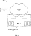
- Fig. 1 is a block diagram of an exemplary environment 100 in which the systems and methods described below may be implemented.
- environment 100 may include a distributed control system 110 (e.g., a distributed physical access control system), a network 120, and an administration device 130.
- Distributed control system 110 may include one or more distributed datasets.
- a distributed dataset includes data that is stored in a distributed (and potentially redundant) fashion in system units 115 that are associated with the distributed dataset.
- distributed datasets are replicated on more than one device. For example, the entire distributed dataset may be stored in all the units 115. In another embodiment, one or more units 115 may store a subset of the distributed dataset. Also, a distributed dataset may be associated with all system units 115 or may be associated with a subset of system units 115.
- control system 110 may exhibit robustness with respect to device failure, as a single point of failure may be avoided. For example, if a particular system unit 115 fails, the other units 115 may continue to operate without loss of data (or with the minimization of loss of data). In another embodiment, a change may be made to the distributed dataset without consensus.
- Network 120 may enable units 115 to communicate with each other and/or may enable administration device 130 to communicate with particular units 115.
- Network 120 may include one or more circuit-switched networks and/or packet-switched networks.
- network 120 may include a local area network (LAN), a wide area network (WAN), a metropolitan area network (MAN), a Public Switched Telephone Network (PSTN), an ad hoc network, an intranet, the Internet, a fiber optic-based network, a wireless network, and/or a combination of these or other types of networks.
- Administration device 130 allows an administrator to connect to a particular unit 115 in order to configure control system 110, change a configuration of control system 110, receive information from control system 110, and/or otherwise administer control system 110.
- Administration device 130 may include any device configured for communicating with one or more of units 115.
- administration device 130 may include a portable communication device (e.g., a mobile phone, a smart phone, a phablet device, a global positioning system (GPS) device, and/or another type of wireless device); a personal computer or workstation; a server device; a laptop, tablet, or another type of portable computer; and/or any type of device with communication capability.
- administration device 130 may be part of unit 115. As such, an administrator may administer control system 110 from one or more of units 115.
- FIG. 1 shows exemplary components of environment 100
- environment 100 may include fewer components, different components, differently arranged components, or additional components than depicted in Fig. 1 .
- any one device in environment 100 (or any group of devices) may perform functions described as performed by one or more other devices in environment 100.
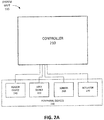
- Figs. 2A and 2B are block diagrams illustrating exemplary components of a unit 115.
- unit 115 may include a controller 210 and one or more peripheral devices 230.
- Controller 210 may control the operation of unit 115, may communicate with other units 115, may communicate with administration device 130, and/or may control peripheral devices 230.
- Peripheral devices 230 may include devices that provide information to controller 210, that are controlled by controller 210, and/or that otherwise communicate with controller 210.
- peripheral devices 230 may include any type of security device.
- peripheral devices 230 may include a security devices such as a reader device 240, a lock device 250, a sensor 260 (e.g., a camera), and/or an actuator 270.
- Housing 222 may enclose the components of controller 210 and may protect the components of controller 210 from the environment.
- housing 222 may include one or more of peripheral devices 230.
- housing 222 may include administration device 130.
- Housing 222 may define the boundaries of one system unit 115 and/or controller 210 from other system units 115 and/or controllers 210 in a multi system unit 115/controller 115 system.
- Actuator 270 may include an actuator device.
- actuator 270 may control an illumination device.
- actuator 270 may include a burglar alarm activator; a speaker to play messages or generate alarm signals; a display device; a motor to move sensor 260 (e.g., control the field of view of a camera or other monitoring device); a motor for opening/closing a door, window, HVAC vent, and/or another opening associated with a secure area; a motor to secure lock device 250 in a locked or unlocked position; a fire extinguishing device; and/or another type of actuator device.
- unit 115 may include fewer components, different components, additional components, or differently arranged components than depicted in Figs. 2A and 2B .
- peripheral devices 230 may include multiple reader devices 240, multiple lock devices 250, multiple sensors 260, and/or multiple actuators 270.
- Peripheral devices 230 may also not include one or more of the devices shown in Fig. 2A .
- any component of unit 115 (or any group of components) may perform the task or tasks described as performed by one or more other components of unit 115.
- exemplary distributed control system 110 includes a physical access distributed control system, other implementations may control systems other than physical access.
- distributed control system 110 may include any type of physical access control systems (e.g., in an operational environment), such as a control system for opening and/or closing a door or controlling physical access to a building or facility.
- Distributed control system 110 may also include a system to control a fan (e.g., start or stop), to initiate an alarm in a building management system (e.g., failed authentication, successful authentication, or to control a robot arm in an industrial automation system.
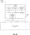
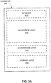
- Fig. 3A is a block diagram illustrating exemplary functional layers of system unit 115.
- unit 115 may include an application program interface (API) layer 310, an application layer 320, a distribution layer 340, and a storage layer 350.
- API application program interface
- Distribution layer 340 may manage one or more distributed datasets associated with units 115. For example, distribution layer 340 may connect controllers 210 in a peer-to-peer network for the distribution of datasets. Distribution layer 340 may use a protocol (e.g., a PAXOS protocol) to establish a consensus with respect to a change in a particular consensus-based distributed dataset. As an example, distribution layer 340 may send a proposal for a change to other system units 115 associated with the distributed dataset and may receive a quorum for the change from the other system units 115. As another example, distribution layer 340 may vote for a proposal received from another unit 115. As yet another example, distribution layer 340 may receive an indication that a consensus has been reached for a change without having voted for the change. When an indication of consensus for a change is received, distribution layer 340 may make the change in the local copy of the distributed dataset. Distribution layer 340 may maintain secure connections with other units 115 over network 120. (e.g., a Transport Layer Security (TLS) connection).
- Storage layer 350 may store one or more datasets associated with unit 115.
- a dataset stored in storage layer 350 may correspond to a local dataset or may correspond to a distributed dataset.
- a local dataset may store information associated with (and/or only associated with) the particular unit 115 that stores the local dataset.
- a distributed dataset may store information that is distributed among other system units 115 associated with the distributed dataset.
- Door control application 324 may control one or more doors and/or associated lock devices 250. For example, door control application 324 may determine whether a door is open or closed and/or locked or unlocked and may operate one or more device to open or close the door and/or to lock or unlock the door.
- Reader control application 326 may control one or more reader devices 240 and may obtain and process credentials received from the one or more reader devices 240.
- Event handling application 328 may process events recorded by unit 115, such as door opening events, alarm events, sensor events, and/or other types of logged events. Event handling application 328 may generate a report and/or an alarm and send the report and/or alarm to administrator device 130 (and/or to another designated device, such as other units 115).
- Schedule handling application 330 may manage one or more schedules associated with unit 115. For example, access rules for particular groups of users may change based on particular times of day.
- Storage layer 350 may include a consensus data area 360 and a non-consensus data area 370.
- consensus data area 360 may include a distributed consensus-based database; and non-consensus data area 370 may include a database that is not consensus based and/or not distributed (i.e., such as the local dataset described above).
- unit 115 may include fewer functional components, different functional components, differently arranged functional components, or additional functional components than depicted in Figs. 3A-3C . Additionally, any one of the components (or any group of components) of unit 115 may perform functions described as performed by one or more other functional components of unit 115. Further, the functional components of unit 115 may be implemented, for example, via hard-wired circuitry of one or more ASICs. Additionally or alternatively, the functional components of unit 115 may be implemented by processor 214 executing instructions from memory 216.
- Fig. 4A is a is a block diagram illustrating system unit 115-A in one configuration.
- unit 115-A includes controller 210-A, reader device 240-A, lock device 250-A, sensor 260-A (e.g., a camera), and an actuator 270-A.
- Unit 115-A may be configured remotely from the location where unit 115-A may be installed. An installer may carry unit 115-A from his workshop to a client's location for installation. Alternatively, unit 115 may come configured to a location for installation through a delivery service, for example.
- unit 115-A may be installed as a stand-alone unit (operating by itself in a network of one) or may be installed in a network of other units 115.
- Fig. 4B is a block diagram illustrating unit 115-A of Fig. 4A in a stand-alone configuration.
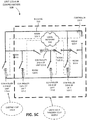
- Figs. 5A- 5C are block diagrams illustrating unit 115-A in a network configuration 500 of other units 115. If unit 115-A is installed in network configuration 500, then unit 115-A may be introduced into an already existing network of other units 115-B through 115-F as shown in Fig. 5B . Alternatively, as shown in Fig. 5C , other units 115-B through 115-F may be added (or joined) to unit 115-A as a stand-alone unit (e.g., as a network of one unit).
- Wall 410 encloses a secure area 440, such as a room in a building.
- Door 420 provides access for a user to secure area 440.
- controller 210-A is installed inside secure area 440.
- controller 210-A may be installed in an insecure area 450.
- Reader device 240-A is installed outside secure area 440 and lock device 250-A is installed inside secure area 440 to wall 410 and door 420.
- Sensor 260-A in this example, is a monitoring device mounted outside secure area 440 in insecure area 450.
- Actuator 270-A includes a motor used to control the field of view of the monitoring device in this example.
- controller 210-A may use the credentials to authenticate the identity of the user and may perform a lookup in an access rules table to determine whether to grant access to the user based on the identity of the user and the access rules. If controller 210-A determines that access should be granted, controller 210-A activates lock device 250-A to unlock door 420, thus granting access to the user to secure area 440.
- Figs. 5A-5C are block diagrams illustrating unit 115-A in a network configuration 500 of other units 115-B through 115-F (e.g., rather than the stand-alone configuration 400 in Fig. 4B ).
- configuration 500 may include a building 510 with rooms 520-A through 520-F.
- a local network 530 such as an Ethernet network, may interconnect system units 115-A through 115-F.
- This example includes the particular unit 115-A described in Fig. 4A in a different environment: in a network of other units 115-B through 115-F rather than stand-alone.
- Unit 115-A in Fig. 5A is configured similarly as unit 115-A in Fig.
- Unit 115-A could have arrived in this configuration in different ways. For example, as demonstrated in Fig. 5C , unit 115-A may have been a single-unit system to which units 115-B through 115-F were added (or joined) over time. Or, as demonstrated in Fig. 5B , unit 115-A may have been added to (or joined) configuration 500 to an existing network that already included units 115-B through 115-F.
- system unit 115-B controls two doors into room 520-B; system unit 115-A controls an outside door into room 520-A; system unit 115-C controls one door from room 520-A to room 520-C, system unit 115-D controls one door from room 520-C to room 520-D; system unit 115-E controls one door from room 520-D to room 520-E; and unit 520-F controls an outside door into room 520-F.
- each unit 115 is associated with a controller 210. Further, in the implementation of Figs. 5A-5C , each controller 210 is in a different location (e.g., different room 520) than other controllers 210. In other implementations, some controllers 210 and units 115 may be located in different buildings, different geographic regions, different nations, different continents, than other controllers and units 115. Despite their diverse locations, in one embodiment, units 115 and controllers 210 may be able to discover each other (or make a best effort to do so), form a pecr-to-peer network, and distribute datasets.
- configuration 500 may include fewer components, different components, additional components, or differently arranged components than depicted in Figs. 5A-5C .
- a central controlling device e.g., a server
- one or more components of configuration 500 may perform one or more tasks described as performed by one or more other components of configuration 500.
- Fig. 6 is a block diagram illustrating exemplary components of administration device 130.
- administration device 130 may include a bus 610, a processor 620, a memory 630, an input device 640, an output device 650, and a communication interface 660.
- Bus 610 includes path that permits communication among the components of administration device 130.
- Processor 620 may include any type of single-core processor, multi-core processor, microprocessor, latch-based processor, and/or processing logic (or families of processors, microprocessors, and/or processing logics) that interprets and executes instructions.
- processor 620 may include an ASIC, an FPGA, and/or another type of integrated circuit or processing logic.
- Memory 630 stores information, data, and/or instructions.
- Memory 630 may include a dynamic, volatile, and/or non-volatile storage device.
- Memory 630 may store instructions, for execution by processor 620, or information for use by processor 620.
- memory 620 may include a RAM, a ROM, a CAM, a magnetic and/or optical recording memory device, etc.
- Input device 640 allows an operator to input information into administration device 130.
- Input device 640 may include, for example, a keyboard, a mouse, a pen, a microphone, a touch-screen display, etc.
- Output device 650 may output information to an operator of administration device 130.
- Output device 650 may include a display, a printer, a speaker, and/or another type of output device.
- Communication interface 660 may include (e.g., a transmitter and/or a receiver) that enables controller 210 to communicate (e.g., transmit and/or receive data) with other devices and/or systems via wired communication links, wireless communication links, or a combination of wireless and wired communication links.
- Communication interface 660 may include a network interface card (e.g., Ethernet card) for wired communications and/or a wireless network interface (e.g., a WiFi) card for wireless communications.
- Administration device 130 may perform operations relating to managing units 115 in system 110. Administration device 130 may perform these operations in response to processor 620 executing software instructions contained in a computer-readable medium, such as memory 630. The software instructions contained in memory 630 may cause processor 620 to perform these operations.
- Fig. 7 is a flowchart of an exemplary process 700 for adding system unit 115-A (or having system unit 115-A join a network) to create network configuration 500 (e.g., a distributed environment with other units 115-B through 115-F).
- Process 700 demonstrates the situation in which unit 115-A becomes a stand-alone unit (configuration 400 of Fig. 4B ) or a unit in a network configuration (configuration 500 of Figs. 5A- 5C either as a first unit or an added unit).
- Process 700 may be performed by control logic 322 and/or distribution layer logic 340 running in controller 210, for example.
- system unit 115-A is to be in network configuration 500, the administrator may not know whether unit 115-A will be the first unit of the network (the situation shown in Fig. 5C in which case it may be a stand-alone device of configuration 400 to start), or be added to an existing network of units 115-B through 115-F (the situation shown in Fig. 5B ).
- the device-specific data (e.g., configuration data or first data) may be stored in a first memory area (e.g., consensus data area 360) in a database for distribution to other controllers 210 (or units 115) (block 704).
- the device-specific data may be stored as device-specific data 362 of consensus data area 360 in storage layer 350.
- unit 115-A is a stand-alone unit, then it is ready to be put in configuration 400 (in a network of one device). Further, unit 115-A is ready to have other units 115 join it to form a larger network of units 115 (the situation of Fig. 5C ). In this latter case, the data in consensus data area 360 may be distributed to other controllers as they are added to unit 115-A.
- system unit 115-A is to join an existing network of units 115-B through 115-F (the situation of Fig. 5B )
- confirmation is received to add controller 210-A (unit 115-A) to a new network (e.g., a peer-to-peer network) distributing a consensus-based database (block 706).
- a new network e.g., a peer-to-peer network
- a consensus-based database (block 706).
- care should be taken to avoid removing, deleting, or overwriting device-specific data 362 provided by the administrator at block 702.
- the system runs the risk of having device-specific data 362 for unit 115-A overwritten because of a lack of consensus.
- one embodiment allows device-specific data 362 to be introduced to the consensus-based DB distributed by units 115-B through 115-F without being overwritten.
- confirmation does not have to be received for system unit 115-A to be added to an existing network.
- device-specific (first) 362 data may be stored in another (e.g., second) memory area (block 708), such as non-consensus data area 370 (see Fig. 3C ).
- unit 115-A i.e., controller 110-A
- the new network may join (or be added to) the new network (block 710) that is distributing the consensus-based database (e.g., the situation of Fig. 5B ) among units 115-B through 115-F (e.g., a peer-to-peer network).
- unit 115-A may receive data from the other devices (units 115-B through 115-F) in the network (e.g., peer-to-peer network) and may add the received data to the consensus-based data area by storing the received data in the first memory area (i.e., consensus data area 360).
- the network e.g., peer-to-peer network
- system unit 115-A is added to network configuration 500 with its device-specific data 362 kept intact and distributed as appropriate.
- Distribution layer 340 distributes the consensus-based data stored in consensus data area 360 (including device-specific data 362).
- device-specific data 362 is tagged with a device identifier (ID) (e.g., a unique device identifier) so as to make a lack of consensus with respect to device-specific data unlikely.
- ID device identifier
- Fig. 8 is a flowchart of an exemplary process 800 for removing unit 115-A from the network configuration 500 shown in Fig. 5A .
- Process 800 begins with the receipt of a confirmation that unit 115-A is to be removed from its existing network configuration 500 (block 802) and that the device-specific (first) data for unit 115-A is to be retained (block 804). If device-specific (first) data is to be retained, then the device-specific (first) data is copied to non-consensus data (second memory) area 370 (block 806) (see Fig. 3C ) (e.g., from consensus data (first memory) area 360.
- System unit 115-A may then leave the network configuration (e.g., be removed from the peer-to-peer network) and the distributed DB may be reset (block 808).
- Resetting the distributed DB may include resetting consensus data area 360 by erasing or deleting data stored in consensus data area 360.
- Device-specific data (first) 362 may then be copied from the non-consensus data (second memory) area 370 to consensus data (first memory) area 360 (block 810).
- the administrator may take unit 115-A out of network 500, for example, while maintaining its device-specific configuration information (e.g., such as configuration information regarding peripherals connected to controller 210-A).
- a component may include hardware, such as a processor, an ASIC, or a FPGA, or a combination of hardware and software (e.g., a processor executing software).
Applications Claiming Priority (1)
| Application Number | Priority Date | Filing Date | Title |
|---|---|---|---|
| US14/028,059 US9621644B2 (en) | 2013-09-16 | 2013-09-16 | Joining a distributed database |
Publications (2)
| Publication Number | Publication Date |
|---|---|
| EP2849062A1 EP2849062A1 (en) | 2015-03-18 |
| EP2849062B1 true EP2849062B1 (en) | 2019-06-26 |
Family
ID=49223671
Family Applications (1)
| Application Number | Title | Priority Date | Filing Date |
|---|---|---|---|
| EP13185578.5A Active EP2849062B1 (en) | 2013-09-16 | 2013-09-23 | Joining a distributed database |
Country Status (6)
| Country | Link |
|---|---|
| US (1) | US9621644B2 (zh) |
| EP (1) | EP2849062B1 (zh) |
| JP (1) | JP6147234B2 (zh) |
| KR (1) | KR101757345B1 (zh) |
| CN (1) | CN104462171B (zh) |
| TW (1) | TWI595370B (zh) |
Families Citing this family (3)
| Publication number | Priority date | Publication date | Assignee | Title |
|---|---|---|---|---|
| US20180147722A1 (en) * | 2016-11-30 | 2018-05-31 | Nanjing Avatarmind Robot Technology Co., Ltd. | Method and system for managing wireless networking of units inside robot |
| US10831917B2 (en) | 2018-10-29 | 2020-11-10 | At&T Intellectual Property I, L.P. | Database system consensus-based access control |
| TWI753716B (zh) * | 2020-12-23 | 2022-01-21 | 財團法人工業技術研究院 | 運動數據收集方法及系統 |
Family Cites Families (15)
| Publication number | Priority date | Publication date | Assignee | Title |
|---|---|---|---|---|
| US6047332A (en) | 1997-06-30 | 2000-04-04 | Sun Microsystems, Inc. | Global file system-based system and method for rendering devices on a cluster globally visible |
| US6243744B1 (en) | 1998-05-26 | 2001-06-05 | Compaq Computer Corporation | Computer network cluster generation indicator |
| US7085805B1 (en) * | 2000-07-07 | 2006-08-01 | Sun Microsystems, Inc. | Remote device management in grouped server environment |
| WO2004081818A1 (en) * | 2003-03-10 | 2004-09-23 | Koninklijke Philips Electronics N.V. | Method and apparatus for ownership transfer of transactions in peer-to-peer systems |
| US20060195361A1 (en) * | 2005-10-01 | 2006-08-31 | Outland Research | Location-based demographic profiling system and method of use |
| US7426653B2 (en) | 2005-04-13 | 2008-09-16 | Progress Software Corporation | Fault tolerant distributed lock management |
| TWI291665B (en) * | 2005-12-30 | 2007-12-21 | Ind Tech Res Inst | Product managing system and method using RFID technology |
| US20070240227A1 (en) * | 2006-03-29 | 2007-10-11 | Rickman Dale M | Managing an entity |
| RU2009120689A (ru) * | 2006-11-02 | 2010-12-10 | Конинклейке Филипс Электроникс, Н.В. (Nl) | Распределенная отмена полномочий устройств |
| US8856206B2 (en) | 2007-08-28 | 2014-10-07 | International Business Machines Corporation | Maintaining message versions at nodes in a network |
| US8122497B2 (en) * | 2007-09-10 | 2012-02-21 | Redcloud, Inc. | Networked physical security access control system and method |
| US8554865B2 (en) | 2007-09-21 | 2013-10-08 | Honeywell International Inc. | System and method for remotely administering and synchronizing a clustered group of access control panels |
| US10296937B2 (en) * | 2009-06-29 | 2019-05-21 | Excalibur Ip, Llc | Operating a sensor recording marketplace |
| US20130124546A1 (en) * | 2010-02-26 | 2013-05-16 | Adobe Systems, Inc. | Group access control for a distributed system |
| US8381017B2 (en) | 2010-05-20 | 2013-02-19 | International Business Machines Corporation | Automated node fencing integrated within a quorum service of a cluster infrastructure |
-
2013
- 2013-09-16 US US14/028,059 patent/US9621644B2/en active Active
- 2013-09-23 EP EP13185578.5A patent/EP2849062B1/en active Active
-
2014
- 2014-09-15 TW TW103131804A patent/TWI595370B/zh active
- 2014-09-15 KR KR1020140121839A patent/KR101757345B1/ko active IP Right Grant
- 2014-09-15 CN CN201410469677.XA patent/CN104462171B/zh active Active
- 2014-09-16 JP JP2014187456A patent/JP6147234B2/ja active Active
Non-Patent Citations (1)
| Title |
|---|
| None * |
Also Published As
| Publication number | Publication date |
|---|---|
| CN104462171A (zh) | 2015-03-25 |
| CN104462171B (zh) | 2019-07-26 |
| EP2849062A1 (en) | 2015-03-18 |
| TW201528012A (zh) | 2015-07-16 |
| US20150081831A1 (en) | 2015-03-19 |
| JP2015057702A (ja) | 2015-03-26 |
| US9621644B2 (en) | 2017-04-11 |
| KR20150032187A (ko) | 2015-03-25 |
| JP6147234B2 (ja) | 2017-06-14 |
| KR101757345B1 (ko) | 2017-07-12 |
| TWI595370B (zh) | 2017-08-11 |
Similar Documents
| Publication | Publication Date | Title |
|---|---|---|
| EP2849061B1 (en) | Distribution of user credentials | |
| EP2849066B1 (en) | Anonymous decisions in an access control system | |
| EP2849068B1 (en) | Distributed events in an access control system | |
| EP2849063B1 (en) | Managing application data in distributed control systems | |
| KR101809994B1 (ko) | 분산 제어 시스템의 컨센서스 로스 | |
| EP2849062B1 (en) | Joining a distributed database |
Legal Events
| Date | Code | Title | Description |
|---|---|---|---|
| PUAI | Public reference made under article 153(3) epc to a published international application that has entered the european phase |
Free format text: ORIGINAL CODE: 0009012 |
|
| 17P | Request for examination filed |
Effective date: 20140722 |
|
| AK | Designated contracting states |
Kind code of ref document: A1 Designated state(s): AL AT BE BG CH CY CZ DE DK EE ES FI FR GB GR HR HU IE IS IT LI LT LU LV MC MK MT NL NO PL PT RO RS SE SI SK SM TR |
|
| AX | Request for extension of the european patent |
Extension state: BA ME |
|
| 17Q | First examination report despatched |
Effective date: 20150430 |
|
| STAA | Information on the status of an ep patent application or granted ep patent |
Free format text: STATUS: EXAMINATION IS IN PROGRESS |
|
| REG | Reference to a national code |
Ref country code: DE Ref legal event code: R079 Ref document number: 602013057027 Country of ref document: DE Free format text: PREVIOUS MAIN CLASS: G06F0009480000 Ipc: H04L0029080000 |
|
| RIC1 | Information provided on ipc code assigned before grant |
Ipc: G06F 11/14 20060101ALI20190114BHEP Ipc: G06F 9/48 20060101ALI20190114BHEP Ipc: H04L 29/08 20060101AFI20190114BHEP Ipc: G06F 11/18 20060101ALI20190114BHEP |
|
| GRAP | Despatch of communication of intention to grant a patent |
Free format text: ORIGINAL CODE: EPIDOSNIGR1 |
|
| STAA | Information on the status of an ep patent application or granted ep patent |
Free format text: STATUS: GRANT OF PATENT IS INTENDED |
|
| INTG | Intention to grant announced |
Effective date: 20190301 |
|
| GRAS | Grant fee paid |
Free format text: ORIGINAL CODE: EPIDOSNIGR3 |
|
| GRAA | (expected) grant |
Free format text: ORIGINAL CODE: 0009210 |
|
| STAA | Information on the status of an ep patent application or granted ep patent |
Free format text: STATUS: THE PATENT HAS BEEN GRANTED |
|
| AK | Designated contracting states |
Kind code of ref document: B1 Designated state(s): AL AT BE BG CH CY CZ DE DK EE ES FI FR GB GR HR HU IE IS IT LI LT LU LV MC MK MT NL NO PL PT RO RS SE SI SK SM TR |
|
| REG | Reference to a national code |
Ref country code: GB Ref legal event code: FG4D |
|
| REG | Reference to a national code |
Ref country code: CH Ref legal event code: EP |
|
| REG | Reference to a national code |
Ref country code: DE Ref legal event code: R096 Ref document number: 602013057027 Country of ref document: DE |
|
| REG | Reference to a national code |
Ref country code: AT Ref legal event code: REF Ref document number: 1149646 Country of ref document: AT Kind code of ref document: T Effective date: 20190715 |
|
| REG | Reference to a national code |
Ref country code: IE Ref legal event code: FG4D |
|
| REG | Reference to a national code |
Ref country code: SE Ref legal event code: TRGR |
|
| REG | Reference to a national code |
Ref country code: NL Ref legal event code: MP Effective date: 20190626 |
|
| PG25 | Lapsed in a contracting state [announced via postgrant information from national office to epo] |
Ref country code: AL Free format text: LAPSE BECAUSE OF FAILURE TO SUBMIT A TRANSLATION OF THE DESCRIPTION OR TO PAY THE FEE WITHIN THE PRESCRIBED TIME-LIMIT Effective date: 20190626 Ref country code: NO Free format text: LAPSE BECAUSE OF FAILURE TO SUBMIT A TRANSLATION OF THE DESCRIPTION OR TO PAY THE FEE WITHIN THE PRESCRIBED TIME-LIMIT Effective date: 20190926 Ref country code: HR Free format text: LAPSE BECAUSE OF FAILURE TO SUBMIT A TRANSLATION OF THE DESCRIPTION OR TO PAY THE FEE WITHIN THE PRESCRIBED TIME-LIMIT Effective date: 20190626 Ref country code: LT Free format text: LAPSE BECAUSE OF FAILURE TO SUBMIT A TRANSLATION OF THE DESCRIPTION OR TO PAY THE FEE WITHIN THE PRESCRIBED TIME-LIMIT Effective date: 20190626 Ref country code: FI Free format text: LAPSE BECAUSE OF FAILURE TO SUBMIT A TRANSLATION OF THE DESCRIPTION OR TO PAY THE FEE WITHIN THE PRESCRIBED TIME-LIMIT Effective date: 20190626 |
|
| REG | Reference to a national code |
Ref country code: LT Ref legal event code: MG4D |
|
| PG25 | Lapsed in a contracting state [announced via postgrant information from national office to epo] |
Ref country code: LV Free format text: LAPSE BECAUSE OF FAILURE TO SUBMIT A TRANSLATION OF THE DESCRIPTION OR TO PAY THE FEE WITHIN THE PRESCRIBED TIME-LIMIT Effective date: 20190626 Ref country code: RS Free format text: LAPSE BECAUSE OF FAILURE TO SUBMIT A TRANSLATION OF THE DESCRIPTION OR TO PAY THE FEE WITHIN THE PRESCRIBED TIME-LIMIT Effective date: 20190626 Ref country code: BG Free format text: LAPSE BECAUSE OF FAILURE TO SUBMIT A TRANSLATION OF THE DESCRIPTION OR TO PAY THE FEE WITHIN THE PRESCRIBED TIME-LIMIT Effective date: 20190926 Ref country code: GR Free format text: LAPSE BECAUSE OF FAILURE TO SUBMIT A TRANSLATION OF THE DESCRIPTION OR TO PAY THE FEE WITHIN THE PRESCRIBED TIME-LIMIT Effective date: 20190927 |
|
| REG | Reference to a national code |
Ref country code: AT Ref legal event code: MK05 Ref document number: 1149646 Country of ref document: AT Kind code of ref document: T Effective date: 20190626 |
|
| PG25 | Lapsed in a contracting state [announced via postgrant information from national office to epo] |
Ref country code: PT Free format text: LAPSE BECAUSE OF FAILURE TO SUBMIT A TRANSLATION OF THE DESCRIPTION OR TO PAY THE FEE WITHIN THE PRESCRIBED TIME-LIMIT Effective date: 20191028 Ref country code: SK Free format text: LAPSE BECAUSE OF FAILURE TO SUBMIT A TRANSLATION OF THE DESCRIPTION OR TO PAY THE FEE WITHIN THE PRESCRIBED TIME-LIMIT Effective date: 20190626 Ref country code: EE Free format text: LAPSE BECAUSE OF FAILURE TO SUBMIT A TRANSLATION OF THE DESCRIPTION OR TO PAY THE FEE WITHIN THE PRESCRIBED TIME-LIMIT Effective date: 20190626 Ref country code: RO Free format text: LAPSE BECAUSE OF FAILURE TO SUBMIT A TRANSLATION OF THE DESCRIPTION OR TO PAY THE FEE WITHIN THE PRESCRIBED TIME-LIMIT Effective date: 20190626 Ref country code: AT Free format text: LAPSE BECAUSE OF FAILURE TO SUBMIT A TRANSLATION OF THE DESCRIPTION OR TO PAY THE FEE WITHIN THE PRESCRIBED TIME-LIMIT Effective date: 20190626 Ref country code: CZ Free format text: LAPSE BECAUSE OF FAILURE TO SUBMIT A TRANSLATION OF THE DESCRIPTION OR TO PAY THE FEE WITHIN THE PRESCRIBED TIME-LIMIT Effective date: 20190626 Ref country code: NL Free format text: LAPSE BECAUSE OF FAILURE TO SUBMIT A TRANSLATION OF THE DESCRIPTION OR TO PAY THE FEE WITHIN THE PRESCRIBED TIME-LIMIT Effective date: 20190626 |
|
| PG25 | Lapsed in a contracting state [announced via postgrant information from national office to epo] |
Ref country code: ES Free format text: LAPSE BECAUSE OF FAILURE TO SUBMIT A TRANSLATION OF THE DESCRIPTION OR TO PAY THE FEE WITHIN THE PRESCRIBED TIME-LIMIT Effective date: 20190626 Ref country code: IS Free format text: LAPSE BECAUSE OF FAILURE TO SUBMIT A TRANSLATION OF THE DESCRIPTION OR TO PAY THE FEE WITHIN THE PRESCRIBED TIME-LIMIT Effective date: 20191026 Ref country code: IT Free format text: LAPSE BECAUSE OF FAILURE TO SUBMIT A TRANSLATION OF THE DESCRIPTION OR TO PAY THE FEE WITHIN THE PRESCRIBED TIME-LIMIT Effective date: 20190626 Ref country code: SM Free format text: LAPSE BECAUSE OF FAILURE TO SUBMIT A TRANSLATION OF THE DESCRIPTION OR TO PAY THE FEE WITHIN THE PRESCRIBED TIME-LIMIT Effective date: 20190626 |
|
| PG25 | Lapsed in a contracting state [announced via postgrant information from national office to epo] |
Ref country code: TR Free format text: LAPSE BECAUSE OF FAILURE TO SUBMIT A TRANSLATION OF THE DESCRIPTION OR TO PAY THE FEE WITHIN THE PRESCRIBED TIME-LIMIT Effective date: 20190626 |
|
| PG25 | Lapsed in a contracting state [announced via postgrant information from national office to epo] |
Ref country code: DK Free format text: LAPSE BECAUSE OF FAILURE TO SUBMIT A TRANSLATION OF THE DESCRIPTION OR TO PAY THE FEE WITHIN THE PRESCRIBED TIME-LIMIT Effective date: 20190626 Ref country code: PL Free format text: LAPSE BECAUSE OF FAILURE TO SUBMIT A TRANSLATION OF THE DESCRIPTION OR TO PAY THE FEE WITHIN THE PRESCRIBED TIME-LIMIT Effective date: 20190626 |
|
| PG25 | Lapsed in a contracting state [announced via postgrant information from national office to epo] |
Ref country code: MC Free format text: LAPSE BECAUSE OF FAILURE TO SUBMIT A TRANSLATION OF THE DESCRIPTION OR TO PAY THE FEE WITHIN THE PRESCRIBED TIME-LIMIT Effective date: 20190626 Ref country code: IS Free format text: LAPSE BECAUSE OF FAILURE TO SUBMIT A TRANSLATION OF THE DESCRIPTION OR TO PAY THE FEE WITHIN THE PRESCRIBED TIME-LIMIT Effective date: 20200224 |
|
| REG | Reference to a national code |
Ref country code: CH Ref legal event code: PL |
|
| REG | Reference to a national code |
Ref country code: DE Ref legal event code: R097 Ref document number: 602013057027 Country of ref document: DE |
|
| PLBE | No opposition filed within time limit |
Free format text: ORIGINAL CODE: 0009261 |
|
| STAA | Information on the status of an ep patent application or granted ep patent |
Free format text: STATUS: NO OPPOSITION FILED WITHIN TIME LIMIT |
|
| PG2D | Information on lapse in contracting state deleted |
Ref country code: IS |
|
| PG25 | Lapsed in a contracting state [announced via postgrant information from national office to epo] |
Ref country code: LU Free format text: LAPSE BECAUSE OF NON-PAYMENT OF DUE FEES Effective date: 20190923 Ref country code: IE Free format text: LAPSE BECAUSE OF NON-PAYMENT OF DUE FEES Effective date: 20190923 Ref country code: LI Free format text: LAPSE BECAUSE OF NON-PAYMENT OF DUE FEES Effective date: 20190930 Ref country code: CH Free format text: LAPSE BECAUSE OF NON-PAYMENT OF DUE FEES Effective date: 20190930 |
|
| REG | Reference to a national code |
Ref country code: BE Ref legal event code: MM Effective date: 20190930 |
|
| 26N | No opposition filed |
Effective date: 20200603 |
|
| PG25 | Lapsed in a contracting state [announced via postgrant information from national office to epo] |
Ref country code: BE Free format text: LAPSE BECAUSE OF NON-PAYMENT OF DUE FEES Effective date: 20190930 Ref country code: SI Free format text: LAPSE BECAUSE OF FAILURE TO SUBMIT A TRANSLATION OF THE DESCRIPTION OR TO PAY THE FEE WITHIN THE PRESCRIBED TIME-LIMIT Effective date: 20190626 |
|
| PG25 | Lapsed in a contracting state [announced via postgrant information from national office to epo] |
Ref country code: CY Free format text: LAPSE BECAUSE OF FAILURE TO SUBMIT A TRANSLATION OF THE DESCRIPTION OR TO PAY THE FEE WITHIN THE PRESCRIBED TIME-LIMIT Effective date: 20190626 |
|
| PG25 | Lapsed in a contracting state [announced via postgrant information from national office to epo] |
Ref country code: HU Free format text: LAPSE BECAUSE OF FAILURE TO SUBMIT A TRANSLATION OF THE DESCRIPTION OR TO PAY THE FEE WITHIN THE PRESCRIBED TIME-LIMIT; INVALID AB INITIO Effective date: 20130923 Ref country code: MT Free format text: LAPSE BECAUSE OF FAILURE TO SUBMIT A TRANSLATION OF THE DESCRIPTION OR TO PAY THE FEE WITHIN THE PRESCRIBED TIME-LIMIT Effective date: 20190626 |
|
| REG | Reference to a national code |
Ref country code: DE Ref legal event code: R079 Ref document number: 602013057027 Country of ref document: DE Free format text: PREVIOUS MAIN CLASS: H04L0029080000 Ipc: H04L0065000000 |
|
| PG25 | Lapsed in a contracting state [announced via postgrant information from national office to epo] |
Ref country code: MK Free format text: LAPSE BECAUSE OF FAILURE TO SUBMIT A TRANSLATION OF THE DESCRIPTION OR TO PAY THE FEE WITHIN THE PRESCRIBED TIME-LIMIT Effective date: 20190626 |
|
| P01 | Opt-out of the competence of the unified patent court (upc) registered |
Effective date: 20230505 |
|
| PGFP | Annual fee paid to national office [announced via postgrant information from national office to epo] |
Ref country code: GB Payment date: 20230823 Year of fee payment: 11 |
|
| PGFP | Annual fee paid to national office [announced via postgrant information from national office to epo] |
Ref country code: SE Payment date: 20230822 Year of fee payment: 11 Ref country code: FR Payment date: 20230822 Year of fee payment: 11 Ref country code: DE Payment date: 20230822 Year of fee payment: 11 |