EP2848880B1 - Refrigerator and shelf assembly for a refrigerator - Google Patents
Refrigerator and shelf assembly for a refrigerator Download PDFInfo
- Publication number
- EP2848880B1 EP2848880B1 EP14184578.4A EP14184578A EP2848880B1 EP 2848880 B1 EP2848880 B1 EP 2848880B1 EP 14184578 A EP14184578 A EP 14184578A EP 2848880 B1 EP2848880 B1 EP 2848880B1
- Authority
- EP
- European Patent Office
- Prior art keywords
- rotation
- gear
- pair
- frame
- handle
- Prior art date
- Legal status (The legal status is an assumption and is not a legal conclusion. Google has not performed a legal analysis and makes no representation as to the accuracy of the status listed.)
- Active
Links
- 230000005540 biological transmission Effects 0.000 claims description 15
- 235000013305 food Nutrition 0.000 description 24
- 230000008878 coupling Effects 0.000 description 10
- 238000010168 coupling process Methods 0.000 description 10
- 238000005859 coupling reaction Methods 0.000 description 10
- 230000005484 gravity Effects 0.000 description 6
- 238000012986 modification Methods 0.000 description 4
- 230000004048 modification Effects 0.000 description 4
- 235000013361 beverage Nutrition 0.000 description 3
- 239000000463 material Substances 0.000 description 3
- 239000000853 adhesive Substances 0.000 description 2
- 230000001070 adhesive effect Effects 0.000 description 2
- 230000006835 compression Effects 0.000 description 1
- 238000007906 compression Methods 0.000 description 1
- 230000001419 dependent effect Effects 0.000 description 1
- 238000007599 discharging Methods 0.000 description 1
- 230000000694 effects Effects 0.000 description 1
- 235000021109 kimchi Nutrition 0.000 description 1
- 229920003023 plastic Polymers 0.000 description 1
- 238000005057 refrigeration Methods 0.000 description 1
- 230000003252 repetitive effect Effects 0.000 description 1
- 238000001338 self-assembly Methods 0.000 description 1
- 235000013311 vegetables Nutrition 0.000 description 1
Images


Classifications
-
- F—MECHANICAL ENGINEERING; LIGHTING; HEATING; WEAPONS; BLASTING
- F25—REFRIGERATION OR COOLING; COMBINED HEATING AND REFRIGERATION SYSTEMS; HEAT PUMP SYSTEMS; MANUFACTURE OR STORAGE OF ICE; LIQUEFACTION SOLIDIFICATION OF GASES
- F25D—REFRIGERATORS; COLD ROOMS; ICE-BOXES; COOLING OR FREEZING APPARATUS NOT OTHERWISE PROVIDED FOR
- F25D25/00—Charging, supporting, and discharging the articles to be cooled
- F25D25/02—Charging, supporting, and discharging the articles to be cooled by shelves
- F25D25/024—Slidable shelves
-
- F—MECHANICAL ENGINEERING; LIGHTING; HEATING; WEAPONS; BLASTING
- F25—REFRIGERATION OR COOLING; COMBINED HEATING AND REFRIGERATION SYSTEMS; HEAT PUMP SYSTEMS; MANUFACTURE OR STORAGE OF ICE; LIQUEFACTION SOLIDIFICATION OF GASES
- F25D—REFRIGERATORS; COLD ROOMS; ICE-BOXES; COOLING OR FREEZING APPARATUS NOT OTHERWISE PROVIDED FOR
- F25D11/00—Self-contained movable devices, e.g. domestic refrigerators
-
- F—MECHANICAL ENGINEERING; LIGHTING; HEATING; WEAPONS; BLASTING
- F25—REFRIGERATION OR COOLING; COMBINED HEATING AND REFRIGERATION SYSTEMS; HEAT PUMP SYSTEMS; MANUFACTURE OR STORAGE OF ICE; LIQUEFACTION SOLIDIFICATION OF GASES
- F25D—REFRIGERATORS; COLD ROOMS; ICE-BOXES; COOLING OR FREEZING APPARATUS NOT OTHERWISE PROVIDED FOR
- F25D23/00—General constructional features
-
- F—MECHANICAL ENGINEERING; LIGHTING; HEATING; WEAPONS; BLASTING
- F25—REFRIGERATION OR COOLING; COMBINED HEATING AND REFRIGERATION SYSTEMS; HEAT PUMP SYSTEMS; MANUFACTURE OR STORAGE OF ICE; LIQUEFACTION SOLIDIFICATION OF GASES
- F25D—REFRIGERATORS; COLD ROOMS; ICE-BOXES; COOLING OR FREEZING APPARATUS NOT OTHERWISE PROVIDED FOR
- F25D25/00—Charging, supporting, and discharging the articles to be cooled
- F25D25/02—Charging, supporting, and discharging the articles to be cooled by shelves
-
- F—MECHANICAL ENGINEERING; LIGHTING; HEATING; WEAPONS; BLASTING
- F25—REFRIGERATION OR COOLING; COMBINED HEATING AND REFRIGERATION SYSTEMS; HEAT PUMP SYSTEMS; MANUFACTURE OR STORAGE OF ICE; LIQUEFACTION SOLIDIFICATION OF GASES
- F25D—REFRIGERATORS; COLD ROOMS; ICE-BOXES; COOLING OR FREEZING APPARATUS NOT OTHERWISE PROVIDED FOR
- F25D25/00—Charging, supporting, and discharging the articles to be cooled
- F25D25/04—Charging, supporting, and discharging the articles to be cooled by conveyors
Definitions
- a refrigerator and a shelf assembly for a refrigerator are disclosed herein.
- a refrigerator is an appliance for storing food, beverages, or other items in a frozen or refrigerated state within a storage compartment by discharging, into the storage compartment, cold air generated through a refrigeration cycle formed by a compressor, a condenser, an expansion valve, and an evaporator.
- the refrigerator generally may include in a cabinet a freezer compartment for storage of food, beverages, or other items in a frozen state, and a fresh food compartment for storage of food, beverages, or other items at a low temperature.
- a Kimchi refrigerator which stores food, such as Kimchi or vegetables, in a fresh state, is another form of refrigerator.
- At least one of a plurality of doors installed at a refrigerator may be connected to a side of the cabinet by a hinge to open or close a front of the cabinet through pivotal movement thereof.
- a drawer type door may also be employed.
- the drawer type door may include a drawer, and a door mounted to a front surface of the drawer to be pulled out or retracted in a forward or rearward direction together with the drawer.
- storage compartments of a refrigerator may be provided with a plurality of shelves that horizontally divide the freezer compartment and the fresh food compartment into sections in order to accommodate items of various sizes and enhance space utilization of the storage compartments.
- the shelves may be installed to be vertically movable in the freezer compartment and fresh food compartment. That is, the shelves may be slidably mounted on a plurality of support ribs formed on or at left and right side surfaces of the freezer compartment and fresh food compartment, or may be mounted on a mount rail having a plurality of vertically formed holes by mounting a pair of cantilevers coupled to the shelves on the mount rail.
- US 2013/081421 A1 relates to a refrigerator according to the preamble of independent claim 1 and, more particularly, to a refrigerator allowing for easily receiving and keeping food items by utilizing space.
- WO 03/095912 A1 relates to a household appliance preferably a refrigerator in which comprising tracks in which the shelves can be easily placed.
- US 2009/308098 A1 relates to a refrigerator, and, more particularly, to a vertically adjustable refrigerator.
- US 2 998 290 A relates to refrigerator cabinets and particularly to a shelf arrangement for such cabinets.
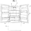
- FIG. 1 is a perspective view of a bottom freezer type refrigerator with a shelf assembly according to an embodiment.
- the refrigerator according to this embodiment includes a cabinet 10 provided therein with a storage compartment and a shelf assembly 100 mounted to the storage compartment and configured to adjust a height of a shelf 110.
- the refrigerator of FIG. 1 is a bottom freezer type refrigerator in which a fresh food compartment 20 is disposed at an upper portion of the cabinet 10, and a freezer compartment is disposed at a lower portion of the cabinet 10.
- a fresh food compartment 20 is disposed at an upper portion of the cabinet 10
- a freezer compartment is disposed at a lower portion of the cabinet 10.
- embodiments are also applicable to any type of refrigerator that allows the shelf assembly 100 to be mounted to or in a storage compartment, such as the fresh food compartment or the freezer compartment.
- Examples or other types of refrigerators include a side-by-side type refrigerator and a top mounting type refrigerator.
- the freezer compartment and the fresh food compartment are arranged side by side.
- the top mounting type refrigerator the freezer compartment is disposed above the fresh food compartment.
- Embodiments are also applicable to a refrigerator provided only with a fresh food compartment or freezer compartment allowing the shelf assembly to be mounted therein.
- the fresh food compartment 20 provided to or at the upper portion of the cabinet 10 may be opened and closed by a pair of fresh food compartment doors 30 pivotably mounted thereto.
- the freezer compartment provided to or at the lower portion of the cabinet 10 may be opened and closed by a freezer compartment door 40, which may be a drawer type door.
- the shelf assembly 110 having a vertically movable shelf 110 may be mounted to a lower portion of the fresh food compartment 20, and another shelf may be arranged on the shelf assembly 110.
- the shelf mounted on the shelf assembly 100 may be supported by a cantilever or a shelf support rib, as shown in FIG. 1 .
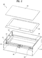
- FIG. 2 is a perspective view of a shelf assembly according to an embodiment.
- FIG. 3 is an exploded perspective view of the shelf assembly of FIG. 2 .
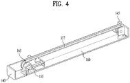
- FIG. 4 is a partially cutaway perspective view of a belt mounted to a rotation gear of the shelf assembly of FIG. 2 .
- the belt shown in FIGs. 3 and 4 is not shown in FIG. 2 .
- the shelf assembly 100 includes a shelf 110 mounted in the storage compartment so as to be vertically movable, a frame 140 configured to vertically move and support the shelf 110, a pair of rotation gears 150 provided to or at both sides of the frame 140, a pair of guide brackets 160 provided to or at both sides of the frame 140, a pair of sliders 170 moved back and forth in the pair of guide brackets 160 by the pair of rotation gears 150, a power transmission configured to transfer rotatory power of the pair of rotation gears 150 to the pair of sliders 170 to horizontally move the pair of sliders 170, at least one pair of guide grooves 132 provided to or at an inner surface of the storage compartment to guide movement of at least one pair of protrusions provided to or at outer side surfaces of the pair of sliders 170, and a rotation device to rotate the pair of rotation gears 150.
- the at least one pair of guide grooves 132 may be slanted.
- the shelf 110 may be a quadrangular plate configured to accommodate objects, such as food placed thereon.
- the accommodated objects may also be stored below the shelf 110, and the shelf 110 may be formed of a transparent or semi-transparent plastic to allow the objects stored below the shelf 110 to be seen therethrough.
- the frame 140 which supports and vertically moves together with the shelf 110, may be disposed along or at an edge of the shelf 110.
- the frame 140 may include a concave portion having an open top.
- the pair of rotation gears 150, the pair of guide brackets 160, the pair of sliders 170, the power transmission, and the rotation device may be mounted to or in the concave portion.
- the frame 140 may be further provided with a frame cover 120 having a plurality of grooves formed therein so as not to interfere with components mounted to or in the concave portion.
- An overall shape of the frame cover 120 may correspond to a shape of the concave portion of the frame 140.
- a portion of the frame cover 120 that overlaps components, such as the pair of rotation gears 150 and the rotation device, may be provided with a groove.
- the frame cover 120 may not only serve to protect components mounted to or in the frame 140, but may also cover complex components to prevent the complex components from being externally exposed through the transparent or semi-transparent shelf 110.
- the pair of rotation gears 150 is rotatably mounted to front portions of both sides of the frame 140.
- a rotation shaft of the pair of rotation gears 150 is laterally mounted to ends of both sides of a front of the frame 140. That is, a rotation gear mounting portion 165 may be separately provided to or in the concave portion of the frame 140.
- the pair of guide brackets 160 is mounted to or at both sides of the frame 140. Each of the pair of guide brackets 160 may be disposed on or at a back of a corresponding one of the pair of rotation gears 150. As the pair of rotation gears 150 is disposed in front of the guide brackets 160, the rotation gear mounting portion 165 may be integrated with the pair of guide brackets 160 and mounted to the frame 140.
- the pair of sliders 170 is inserted into and slidably mounted to the pair of guide brackets 160.
- the pair of sliders 170 is allowed to slide within the pair of guide brackets 160 by the pair of rotation gears 150. That is, the pair of guide brackets 160 and the pair of sliders 170 may be formed of a material producing low friction therebetween.
- Each of the guide brackets 160 may have a " ⁇ "-shaped cross section so as to support both an upper portion and a lower portion of a corresponding one of the pair of sliders 170.
- the pair of sliders 170 are moved back and forth by the pair of rotation gears 150.
- belts 157 and gear type pulleys are used as the power transmission to transmit rotatory power of the pair of rotation gears 150 to the pair of sliders 170 to horizontally move the sliders 170.
- driven gears 152 connected to the pair of rotation gears 150 by the belt 157 may further be provided.
- an inner surface of belt 157 installed between the rotation gear 150 and the driven gear 152 may be provided with grooves equally spaced from each other to correspond to grooves of the gears.
- the rotation gear 150 and the belt 157 do not rotate only in one direction. Rather, they rotate back and forth within a predetermined range. Accordingly, not all of the inner surface of the belt 157 may be provided with grooves.
- the belts 157 may be attached to the lower surfaces of the pair of sliders 170 by an adhesive, or may be coupled to the lower surfaces by a coupling member, such as a screw.
- a pair of protrusions is provided to or at an exterior of each of the pair of sliders 170.
- the pair of protrusions may include at least one pair of rollers 172 rotatably mounted to an exterior of the pair of sliders 170.
- Rotation shafts of the rollers 172 may be horizontally mounted to the exterior of the pair of sliders 170.
- Each of the pair of sliders 170 may be provided with two rollers 172.
- the at least one pair of rollers 172 may be inserted into at least one pair of guide grooves 132 (see FIG. 2 ) provided an inner side surfaces of the storage compartment, such that movement of the rollers 172 may be guided by the grooves.
- the pair of guide grooves 132 is slanted.
- the guide grooves 132 are illustrated as being formed on inner surface of a case 130 of the shelf assembly 100 in FIG. 2 , the guide grooves 132 may be formed on both sides of the fresh food compartment 20, which is a storage compartment, in the same pattern. Each of the guide grooves 132 formed on both side surfaces of the fresh food compartment 20 may be provided with a horizontal portion in addition to an inclined portion and a vertical portion to allow the rollers 172 to be inserted thereinto with the shelf assembly 100 assembled.
- the case 130 may be a box formed in the shape of a rectangular parallelepiped having an open top and front.
- the frame 140 connected with the shelf 110 and mounted to the case 130 may be more conveniently seated in the fresh food compartment 20.
- the two pairs of guide grooves 132 formed on the inner surface of the case 130 may be provided with inclined portions and vertical portions. Thereby, the at least one pair of rollers 172 may be easily inserted and installed through the vertical portions.
- the pair of rotation gears 150 is connected to each other to be rotated together by a rotation bar 155 rotatably mounted to the concave portion of the frame 14.
- a cross section of the rotation bar 155 may be formed in a quadrangular shape so as to be rotated by a handle 180, which will be described hereinbelow.
- the rotation bar 155 may be rotatably mounted to the concave portion of the frame 140 by a bearing 188 having a quadrangular hole and a bracket 187 having a screw fastening hole.
- the pair of rotation gear 150 may be mounted to the rotation gear mounting portion 165.
- the rotation bar 155 may be inserted into a quadrangular groove formed at an inner side of the rotation gear 150.
- a middle portion of the rotation bar 155 needs to be securely and rotatably fixed. Accordingly, the middle portion of the rotation bar 155 may be mounted to the concave portion of the frame 140 by a pair of the bearings 188 and a pair of the brackets 187.
- the rotation device to rotate the pair of rotation gears 150 includes the rotation bar 155, a unidirectional rotation gear 185 mounted to the rotation bar 155, and the handle 180 rotatably mounted to the frame 140 and provided at a rear end thereof with an arc-shaped gear 182 engaged with the unidirectional rotation gear 185 to rotate the unidirectional rotation gear 185.
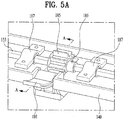
- FIGs. 5A-5B show an enlarged perspective view and a cross-sectional view of a handle of the shelf assembly of FIG. 2 .
- a front central portion of the frame 140 may be provided with a recessed portion 148 to which the handle 180 and the unidirectional rotation gear 185 may be mounted.
- the handle 180 may be mounted by inserting a pivot pin 183 into a pin hole (not shown) formed in the recessed portion 148 and a pivot hole 181 formed in a central portion of the handle 180.
- the handle 180 may extend from the pivot hole 181 by a predetermined length to protrude from the recessed portion 148 such that a front end of the handle 180 may be easily pushed by a finger.
- the arc-shaped gear 182 may be formed at an end of the handle 180 to extend from an opposite side of the pivot hole 181 so as to be selectively engaged with the unidirectional rotation gear 185.
- the unidirectional rotation gear 185 rotates together with the rotation bar 155 when rotated in a first direction by the arc-shaped gear 182 of the handle 180.
- the unidirectional rotation gear 185 when the unidirectional rotation gear 185 is rotated in a second opposite direction, it runs idle without rotation of the rotation bar 155. That is, the unidirectional rotation gear 185 may be mounted to the rotation bar 155 by a clutch bearing 186 disposed between the unidirectional rotation gear 185 and the rotation bar 155. Referring to FIG. 5B , rotatory power of the unidirectional rotation gear 185 produced clockwise may be transmitted to the rotation bar 155 by the clutch bearing 186, while the rotatory power produced counterclockwise may not be transmitted to the rotation bar 155.
- the pair of rotation gears 150 connected to both ends of the rotation bar 155 may be rotated simultaneously by a predetermined angle when the handle 180 rotates the unidirectional rotation gear 185 in the first direction, and be returned to an original position thereof by rotating in the second opposite direction. Subsequently, by rotating the handle 180 again, the pair of rotation gears 150 may be rotated by another predetermined angle.
- an elastic member (not shown) may be provided between the handle 180 and the frame 140.
- the elastic member may be, for example, a torsion spring installed at the pivot shaft of the handle 180, or may be a compression spring or a tension spring placed between and connected to one side of the arc-shaped gear 182 and the frame 140.
- the pair of sliders 170 When the user rotates the pair of rotation gears 150 by a predetermined angle by rotating the handle 180, the pair of sliders 170 is moved forward by a predetermined distance by the belt 157.
- the rollers 172 provided to the exterior of the pair of sliders 170 rise by being guided by the guide grooves 132. Thereby, the frame 140 and the shelf 110 mounted thereto are raised to a predetermined height.
- FIG. 6 is a partial perspective view of a coupling between a lever mounted to a side of a frame and a stopper gear mounted to a side of a rotation bar according to an embodiment.
- the shelf assembly 100 further includes a stopper gear 195 mounted to one side of the rotation bar 155 to rotate together with the rotation bar, and a lever 190 rotatably mounted to one side of the frame 140 and engaged with the stopper gear 195 to prevent rotation of the stopper gear 195 in one direction.
- the handle 180 which is a rotation device provided to or at the front central portion of the frame 140, raises the frame 140, but cannot resist downward movement of the frame 140 due to gravity.
- the unidirectional rotation gear 185 is mounted to the rotation bar 155 by the clutch bearing 186, it cannot stop counterclockwise rotation of the rotation bar 155 with respect to FIG. 5B .
- the stopper gear 195 which rotates together with the rotation bar 155 in normal and reverse directions, is mounted to the rotation bar 155, and the lever 190 engaged with the stopper gear 195 to allow the stopper gear 195 to rotate only in the first direction may be mounted to a front of the stopper gear 195. Thereby, rotation of the rotation bar 155 in the second direction is selectively prevented. That is, one end of the lever 190 may be provided with a locking protrusion 192 selectively engaged with the stopper gear 195.
- a pivot shaft 191 of the lever 190 may be mounted to a lever mounting portion 149 provided to one side of the front of the frame 140, and the front end of the lever 190 may extend downward of the frame 140.
- the locking protrusion 192 may be formed at a rear end of the pivot shaft 191 and extend downward in a rearward direction.
- the locking protrusion 192 may be formed of a material which is elastically deformable to a predetermined extent.
- An outer circumferential surface of the stopper gear 195 may be provided with a plurality of teeth inclined by a predetermined angle with respect to a radial direction of the stopper gear 195. Thereby, rotation of the stopper gear 195 in the first direction may be restricted by the locking protrusion 192, but the stopper gear 195 may rotate in the second opposite direction without being restricted by the locking protrusion 192 as the locking protrusion 192 is elastically deformed.
- the user may lift the lever 190, thereby allowing the rotation bar 155 and the pair of rotation gears 150 to rotate in the second opposite direction by gravity.
- the stopper gear 195 may rotate as the locking protrusion 192 is released from the stopper gear 195.
- the frame 140 and the shelf 110 may be lowered as the rotation bar 155 and the rotation gears 150 rotate by gravity.
- the rotation angle by which the pair of rotation gears 150 rotate when the lever 190 is lifted once may be determined by a space between the teeth of the stopper gear 195. If the lever 190 is held lifted, the pair of rotation gears 150 may continue to rotate, and the frame 140 and the shelf 110 may be lowered until the rollers 172 of the pair of sliders 170 are supported by lowermost ends of the guide grooves 132.
- guide protrusions 145 may be provided at both sides of the frame 140, and guide grooves 135, into which the guide protrusions 145 may be slidably inserted, may be vertically formed on both inner side surfaces of the storage compartment or the case 130, as shown in FIGs. 2 and 3 . Thereby, vertical movement of the frame 140 may be guided.
- a pair of coupling protrusions 144 may be formed at both sides of the frame 140.
- the guide protrusions 145 may be press-fitted into the coupling protrusions 144 or joined to the coupling protrusions 144 by, for example, an adhesive or a screw.
- guide protrusions 145 As the guide protrusions 145 are inserted into the guide grooves 135 to slide therein, they may be formed, as members separate from the frame 140, of a material producing lower friction therebetween. The guide protrusions 145 may be inserted into the guide grooves 135 to support the frame 140 such that the frame 140 does not move back and forth.
- the handle and the lever of this embodiment may be arranged not to protrude from the frame and the shelf.
- the handle 180 may be mounted to a front left corner of the frame 140, and the unidirectional rotation gear 185 may be installed at a back of the handle 180.
- a cutaway 180a having a shape corresponding to that of the handle 180 may be formed at a front left corner of the shelf 110 to allow the handle 180 to be exposed without being covered by the shelf 110, as shown in FIG. 7 . Thereby, a user may push the handle 180 downward.
- the handle 180 of this embodiment may be mounted to a lower portion of the frame 140.
- the pivot shaft 181 of the handle 180 may be mounted to the lower portion of the frame 140, and a rear end of the pivot shaft 181 is provided with an arc-shaped gear 182.
- the pivot shaft 181 may be arranged closer to the arc-shaped gear 182 than to the handle 180. Accordingly, in rotating the unidirectional rotation gear 185 and the pair of rotation gears 150, the handle 180 may need to be pushed by a relatively long distance, but less force may be required.
- the belt 157 installed between the pair of rotation gear 150 and the driven gear 152 is not shown in FIG. 9 .
- the lever 190 may be mounted to a front right corner of the frame 140.
- details of the lever 190 are the same as those in the previous embodiment, except that the front end of the lever 190 may have a shape corresponding to that of a cutaway 190a formed at the front right corner of the frame 140.
- bracket 187 may be installed to be adjacent to the stopper gear 195.
- Another bracket 187 may be installed to be adjacent to the unidirectional rotation gear 185.
- force may be applied to both ends of the rotation bar 155, but not to a central portion of the rotation bar 155. Therefore, portions of the rotation bar 155 near both ends of the rotation bar 155 may be supported by the brackets 187 and bearings.
- gear mounting portion 165 (see FIG. 4 ) mounted to a front of the guide brackets 160 illustrated in previous embodiment may not be needed. This is because the brackets 187 and bearings may be installed at positions close to the pair of rotation gears 150.
- the handle 180 and the lever 190 do not protrude from an outline of the shelf 110 and the frame 140, but form a continuous surface, respectively. Accordingly, compared to the shelf assembly of the previous embodiment having the handle 180 protruding from the shelf, the shelf assembly 100 according to this embodiment may not interfere with the introduction or retrieval of objects.
- FIG. 11 is a partial cutaway perspective view illustrating coupling between a rack of a slider and a rotation gear in a shelf assembly according to another embodiment.
- the pair of sliders 170 slidably guided by the pair of guide brackets 160, and more particularly, upper surfaces of front portions of the pair of sliders 170 may be provided with a rack 175 or rack teeth.
- the pair of rotation gears 150 may be pinions engaged with the rack 175 to move the sliders 170 forward by rotating.
- the pair of rotation gears 150 may move the sliders 170 only forward according to unidirectional rotation of a unidirectional rotation gear 185 (see FIG. 9 ), and when the user lifts the lever 190 (see FIG. 10 ), the sliders 170 may move backward due to gravity.
- a rack and a pinion are used as the power transmission.
- reliability of power transmission and durability may be higher than in the case in which the belt is used.
- This shelf assembly is different from the previous embodiments in that the shelf assembly employs a rotary knob and a worm gear, rather than a handle rotated by being pushed, as a rotation device to rotate the gears.
- FIG. 12 is an exploded perspective view of this shelf assembly.
- FIG. 13 is a partial cutaway perspective view illustrating movement of a rack of a slider through rotation of a rotation gear according to rotation of the rotary knob of FIG. 12 .
- FIGs. 14A-14B are partial perspective views illustrating elevation of shelves and a frame supported by guide grooves of a case according to rotation of the rotary knob of the shelf assembly of FIG. 12 .
- a lower portion of one side of a front of the frame 140 may be provided with a mount 148 to which a knob 1800 may be rotatably mounted.
- a coupling case 1804 may be coupled to the lower portion of the frame 140 by fastening the coupling case 1804 with, for example, a screw.
- a rear surface of the knob 1800 may be provided with a rotation shaft 1801 that extends rearward.
- a front end of the rotation shaft 1801 may be coupled to the knob 1800, and a rear end of the rotation shaft 1801 may be coupled with a worm 1802.
- a worm gear 1803 may be mounted to or on the rotation bar 155 and coupled to the rotation gears 150. Thereby, the worm gear 1803 and the rotation bar 155 may rotate together.
- the worm 1802 When the knob 1800 is rotated, the worm 1802 may in turn rotate the worm gear 1803. Thereby, the rotation bar 155 and the rotation gears 150 may simultaneously rotate.
- the rotation bar 155 may be mounted to or at a front upper surface of the frame 140. In this embodiment, the rotation bar 155 is shown mounted by three pairs of brackets and bearings; however, embodiments are not limited thereto.
- bracket 1805 disposed on the right side may be subjected to force applied according to rotation of the knob 1800. Accordingly, the bracket 1805 may be formed to be larger than the other brackets to securely and rotatably fix the rotation bar 155.
- this shelf assembly may employ a rack and pinion as the power transmission.
- the knob 1800 when the knob 1800 is rotated in a first direction, the worm 1802 may in turn rotate the worm gear 1803, and at the same time, the rotation bar 155 and the rotation gears 150 may rotate.
- the rotation gears 150 which may be pinion gears, may move the rack 175 of the slider 170 in a forward direction.
- the rollers 172 provided to or at the exterior of the slider 170 may rise along the inclined guide groove 132, raising the frame 140.
- the guide protrusions 145 inserted into the guide grooves 135 may be guided to move only in the vertical direction as described above, and thus, the frame 140 may vertically rise.
- FIG. 14A shows the frame 140 lowered to a lower limit
- FIG. 14B shows the frame 140 raised to an upper limit.
- the raised frame 140 may be lowered by turning the knob 1800 in a second opposite direction.
- the elevation and speed of the frame 140 may be properly adjusted according to a length, inclination angle, and position of the guide grooves 135 and a gear ratio between the gears forming the power transmission and rotation device.
- the worm gear cannot rotate the worm due to the nature of the worm and worm gear, and therefore the frame 140 does not move down by gravity when the knob 1800 is not held by a hand.
- the rotation device of this embodiment including the worm and the worm gear may not only function to rotate the rotation gears 150, but also serve as a stopper that prevents the frame 140 from moving down by gravity.
- a user may easily adjust a height of a shelf with less force by pivoting or rotating a handle, such that a slider may be guided by an inclined guide groove.
- a shelf may be moved while being horizontally balanced.
- shelves may be vertically moved with food or other items placed thereon. Accordingly, the shelves may be conveniently used.
- Embodiments disclosed herein provide a refrigerator having a shelf assembly that allows a user to easily adjust a height of shelves by applying less force.
- Embodiments disclosed herein provide a refrigerator that includes a cabinet provided therein with a storage compartment, and a shelf assembly mounted to the storage compartment, the shelf assembly being configured to adjust a height of a shelf.
- the shelf assembly includes a frame mounted to be vertically movable in the storage compartment, a shelf supported by the frame and configured to vertically move, a pair of rotation gears provided to or at opposite sides of the frame, a pair of guide brackets provided to or at the opposite sides of the frame, a pair of sliders moved back and forth within the pair of guide brackets by the pair of rotation gears, an exterior of each of the sliders being provided with at least one pair of protrusions, a power transmission unit or power transmission configured to transmit rotatory power of the rotation gears to the sliders to horizontally move the sliders, at least one pair of guide grooves slantly formed on an inner surface of the storage compartment to guide movement of the at least one pair of protrusions, and a rotation device configured to rotate the pair of rotation gears.
- the rotation device includes a rotation bar laterally arranged to or at a front of the frame to rotate together with the pair of rotation gears, a unidirectional rotation gear mounted to the rotation bar, and a handle pivotably mounted to the frame.
- the refrigerator also includes a stopper gear mounted to one side of the rotation bar to rotate together with the rotation bar, and a lever pivotably mounted to one side of the frame to be engaged with the stopper gear to prevent the stopper gear from rotating in one direction.
- the at least one pair of protrusions may include rollers rotatably mounted to an exterior of each of the sliders.
- the rotation gears may include a drive gear disposed at a front of the guide brackets and a driven gear disposed at a back of the guide brackets.
- the power transmission unit may be a belt coupled between the drive gear and the driven gear, an inner circumferential surface of the belt being provided with teeth.
- the rotation gears may be pinions.
- the power transmission unit may be racks formed at one side of each of the sliders, the rack being engaged with and driven by the pinions.
- a rear end of the handle being provided with an arc-shaped gear engaged with the unidirectional rotation gear to rotate the unidirectional rotation gear.
- the handle is pivotably mounted to a front side of the unidirectional rotation gear at the frame, and a front end of the handle may extend forward.
- the unidirectional rotation gear may include a clutch bearing disposed between the unidirectional rotation gear and the rotation bar.
- the refrigerator may further include an elastic member installed between the handle and the frame to return the handle to an original position of the handle.
- One end of the lever may be provided with a locking protrusion selectively engaged with the stopper gear.
- the stopper gear When the stopper gear is engaged with the locking protrusion, the stopper gear may be supported such that the stopper gear does not rotate in the one direction, but is rotatable in the other direction.
- the handle may be pivotably mounted to a front side of the unidirectional rotation gear at the frame.
- a cutaway part having a shape corresponding to a front end of a pivot shaft of the handle may be provided to or at one side of a front of the shelf, and a front end of the handle may not protrude from a front end of the shelf.
- Both side parts of the frame may be provided with a guide protrusion.
- Both inner side surfaces of the storage compartment may be provided with a guide groove vertically formed to allow the guide protrusion to be slidably inserted thereinto, the guide groove guiding vertical movement of the frame.
- the shelf assembly may include a case having an open front and an open top, a frame mounted to be vertically movable in the case.
- a handle may be rotatably mounted to one side of a front of the frame.
- the rotation gears can be rotated by operation of the handle.
- the at least one pair of guide grooves slantly formed on an inner surface of the case guide movement of rollers protruding from an exterior of the pair of sliders.
- the rotation gears may be connected to each other and rotated together by a rotation bar rotatably mounted to a front of the frame in a lateral direction.
- any reference in this specification to "one embodiment,” “an embodiment,” “example embodiment,” etc. means that a particular feature, structure, or characteristic described in connection with the embodiment is included in at least one embodiment of the invention.
- the appearances of such phrases in various places in the specification are not necessarily all referring to the same embodiment.
Landscapes
- Engineering & Computer Science (AREA)
- Chemical & Material Sciences (AREA)
- Combustion & Propulsion (AREA)
- Physics & Mathematics (AREA)
- Mechanical Engineering (AREA)
- Thermal Sciences (AREA)
- General Engineering & Computer Science (AREA)
- Refrigerator Housings (AREA)
Description
- A refrigerator and a shelf assembly for a refrigerator are disclosed herein.
- Generally, a refrigerator is an appliance for storing food, beverages, or other items in a frozen or refrigerated state within a storage compartment by discharging, into the storage compartment, cold air generated through a refrigeration cycle formed by a compressor, a condenser, an expansion valve, and an evaporator. The refrigerator generally may include in a cabinet a freezer compartment for storage of food, beverages, or other items in a frozen state, and a fresh food compartment for storage of food, beverages, or other items at a low temperature. A Kimchi refrigerator, which stores food, such as Kimchi or vegetables, in a fresh state, is another form of refrigerator.
- At least one of a plurality of doors installed at a refrigerator may be connected to a side of the cabinet by a hinge to open or close a front of the cabinet through pivotal movement thereof. In addition to such a door that pivots about a hinge, a drawer type door may also be employed. The drawer type door may include a drawer, and a door mounted to a front surface of the drawer to be pulled out or retracted in a forward or rearward direction together with the drawer.
- Generally, storage compartments of a refrigerator, namely, a freezer compartment and a fresh food compartment, may be provided with a plurality of shelves that horizontally divide the freezer compartment and the fresh food compartment into sections in order to accommodate items of various sizes and enhance space utilization of the storage compartments. As items of various sizes need to be placed on the shelves, the shelves may be installed to be vertically movable in the freezer compartment and fresh food compartment. That is, the shelves may be slidably mounted on a plurality of support ribs formed on or at left and right side surfaces of the freezer compartment and fresh food compartment, or may be mounted on a mount rail having a plurality of vertically formed holes by mounting a pair of cantilevers coupled to the shelves on the mount rail.
- In conventional cases, however, when a user desires to adjust a height of a mounted shelf, the user needs to remove all items from the shelf, separate the shelf from the support ribs or mount rail, and then install the shelf at another position. Accordingly, adjusting the height of a shelf is difficult and inconvenient.
- Hence, a shelf assembly supported by a worm gear that allows a user to rotate the shelves has been proposed. However, manipulating this assembly requires the user to apply a great force, and reliability of adjustment of the height of the shelves and durability may be degraded.
-
US 2013/081421 A1 relates to a refrigerator according to the preamble of independent claim 1 and, more particularly, to a refrigerator
allowing for easily receiving and keeping food items by utilizing space. -
WO 03/095912 A1 -
US 2009/308098 A1 relates to a refrigerator, and, more particularly, to a vertically adjustable refrigerator. -
DE 20 2007 013356 U1 relates to a device for adjusting a shelf or a placing unit of a refrigerator and/or freezer unit. -
US 2 998 290 A relates to refrigerator cabinets and particularly to a shelf arrangement for such cabinets. - It is an object of the invention to provide a refrigerator and a shelf assembly for a refrigerator. This object is achieved with the features of the independent claim. The dependent claims relate to further aspect of the invention.
- Embodiments will be described in detail with reference to the following drawings in which like reference numerals refer to like elements, and wherein:
-
FIG. 1 is a perspective view of a bottom freezer type refrigerator with a shelf assembly according to an embodiment; -
FIG. 2 is a perspective view of a shelf assembly according to an embodiment; -
FIG. 3 is an exploded perspective view of the shelf assembly ofFIG. 2 ; -
FIG. 4 is a partially cutaway perspective view of a belt mounted to a rotation gear of the shelf assembly ofFIG. 2 ; -
FIGs. 5A and5B show an enlarged perspective view and a cross-sectional view of a handle of the self assembly ofFIG. 2 ; -
FIG. 6 is a partial perspective view of a coupling between a lever mounted to a side of a frame and a stopper gear mounted to a side of a rotation bar according to an embodiment; -
FIG. 7 is a perspective view of a frame and shelves of a shelf assembly according to another embodiment; -
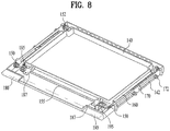
FIG. 8 is a perspective view of the shelf assembly ofFIG. 7 , with the shelves removed; -
FIG. 9 is a partial perspective view illustrating operation of a handle ofFIG. 8 ; -
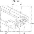
FIG. 10 is a partial perspective view illustrating operation of a lever and stopper gear ofFIG. 8 ; -
FIG. 11 is a partial perspective view illustrating coupling between a rack of a slider and a rotation gear in a shelf assembly according to another embodiment; -
FIG. 12 is an exploded perspective view of a shelf assembly according to another shelf assembly which is not part of the invention; -
FIG. 13 is a partial cutaway perspective view illustrating movement of a rack of a slider through rotation of a rotation gear according to rotation of a handle ofFIG. 12 ; and -
FIGs. 14A-14B are partial perspective views illustrating elevation of shelves and a frame supported by guide grooves of a case according to rotation of the handle of the shelf assembly ofFIG. 12 . - Reference will now be made in detail to embodiments, examples of which are illustrated in the accompanying drawings. Wherever possible, the same reference numbers will be used throughout the drawings to refer to the same or like parts, and repetitive disclosure has been omitted.
-
FIG. 1 is a perspective view of a bottom freezer type refrigerator with a shelf assembly according to an embodiment. The refrigerator according to this embodiment includes acabinet 10 provided therein with a storage compartment and ashelf assembly 100 mounted to the storage compartment and configured to adjust a height of ashelf 110. - The refrigerator of
FIG. 1 is a bottom freezer type refrigerator in which afresh food compartment 20 is disposed at an upper portion of thecabinet 10, and a freezer compartment is disposed at a lower portion of thecabinet 10. However, embodiments are also applicable to any type of refrigerator that allows theshelf assembly 100 to be mounted to or in a storage compartment, such as the fresh food compartment or the freezer compartment. - Examples or other types of refrigerators include a side-by-side type refrigerator and a top mounting type refrigerator. In the side-by-side type refrigerator, the freezer compartment and the fresh food compartment are arranged side by side. In the top mounting type refrigerator, the freezer compartment is disposed above the fresh food compartment. Embodiments are also applicable to a refrigerator provided only with a fresh food compartment or freezer compartment allowing the shelf assembly to be mounted therein.
- The
fresh food compartment 20 provided to or at the upper portion of thecabinet 10 may be opened and closed by a pair of freshfood compartment doors 30 pivotably mounted thereto. The freezer compartment provided to or at the lower portion of thecabinet 10 may be opened and closed by afreezer compartment door 40, which may be a drawer type door. - In the
fresh food compartment 20, theshelf assembly 110 having a verticallymovable shelf 110 may be mounted to a lower portion of thefresh food compartment 20, and another shelf may be arranged on theshelf assembly 110. The shelf mounted on theshelf assembly 100 may be supported by a cantilever or a shelf support rib, as shown inFIG. 1 . -
FIG. 2 is a perspective view of a shelf assembly according to an embodiment.FIG. 3 is an exploded perspective view of the shelf assembly ofFIG. 2 .FIG. 4 is a partially cutaway perspective view of a belt mounted to a rotation gear of the shelf assembly ofFIG. 2 . For simplicity of illustration, the belt shown inFIGs. 3 and4 is not shown inFIG. 2 . - The
shelf assembly 100 includes ashelf 110 mounted in the storage compartment so as to be vertically movable, aframe 140 configured to vertically move and support theshelf 110, a pair ofrotation gears 150 provided to or at both sides of theframe 140, a pair ofguide brackets 160 provided to or at both sides of theframe 140, a pair ofsliders 170 moved back and forth in the pair ofguide brackets 160 by the pair ofrotation gears 150, a power transmission configured to transfer rotatory power of the pair ofrotation gears 150 to the pair ofsliders 170 to horizontally move the pair ofsliders 170, at least one pair ofguide grooves 132 provided to or at an inner surface of the storage compartment to guide movement of at least one pair of protrusions provided to or at outer side surfaces of the pair ofsliders 170, and a rotation device to rotate the pair ofrotation gears 150. The at least one pair ofguide grooves 132 may be slanted. - The
shelf 110 may be a quadrangular plate configured to accommodate objects, such as food placed thereon. The accommodated objects may also be stored below theshelf 110, and theshelf 110 may be formed of a transparent or semi-transparent plastic to allow the objects stored below theshelf 110 to be seen therethrough. Theframe 140, which supports and vertically moves together with theshelf 110, may be disposed along or at an edge of theshelf 110. - Several components to implement an operational mechanism of the shelf assembly may be mounted to or on the
frame 140. That is, theframe 140 may include a concave portion having an open top. The pair of rotation gears 150, the pair ofguide brackets 160, the pair ofsliders 170, the power transmission, and the rotation device may be mounted to or in the concave portion. - The
frame 140 may be further provided with aframe cover 120 having a plurality of grooves formed therein so as not to interfere with components mounted to or in the concave portion. An overall shape of theframe cover 120 may correspond to a shape of the concave portion of theframe 140. A portion of theframe cover 120 that overlaps components, such as the pair of rotation gears 150 and the rotation device, may be provided with a groove. Theframe cover 120 may not only serve to protect components mounted to or in theframe 140, but may also cover complex components to prevent the complex components from being externally exposed through the transparent orsemi-transparent shelf 110. - The pair of rotation gears 150 is rotatably mounted to front portions of both sides of the
frame 140. A rotation shaft of the pair of rotation gears 150 is laterally
mounted to ends of both sides of a front of theframe 140. That is, a rotationgear mounting portion 165 may be separately provided to or in the concave portion of theframe 140. - The pair of
guide brackets 160 is mounted to or at both sides of theframe 140. Each of the pair ofguide brackets 160 may be disposed on or at a back of a corresponding one of the pair of rotation gears 150. As the pair of rotation gears 150 is disposed in front of theguide brackets 160, the rotationgear mounting portion 165 may be integrated with the pair ofguide brackets 160 and mounted to theframe 140. - The pair of
sliders 170 is inserted into and slidably mounted to the pair ofguide brackets 160. The pair ofsliders 170 is allowed to slide within the pair ofguide brackets 160 by the pair of rotation gears 150. That is, the pair ofguide brackets 160 and the pair ofsliders 170 may be formed of a material producing low friction therebetween. Each of theguide brackets 160 may have a "⊏"-shaped cross section so as to support both an upper portion and a lower portion of a corresponding one of the pair ofsliders 170. - The pair of
sliders 170 are moved back and forth by the pair of rotation gears 150. With this embodiment,belts 157 and gear type pulleys are used as the power transmission to transmit rotatory power of the pair of rotation gears 150 to the pair ofsliders 170 to horizontally move thesliders 170. In addition to the pair of rotation gears 150 serving as drive gears, drivengears 152 connected to the pair of rotation gears 150 by thebelt 157 may further be provided. - Like a timing belt, an inner surface of
belt 157 installed between therotation gear 150 and the drivengear 152 may be provided with grooves equally spaced from each other to correspond to grooves of the gears. Therotation gear 150 and thebelt 157 do not rotate only in one direction. Rather, they rotate back and forth within a predetermined range. Accordingly, not all of the inner surface of thebelt 157 may be provided with grooves. As thebelts 157 rotate back and forth by being engaged with lower surfaces of the pair ofsliders 170, the pair ofsliders 170 may be moved back and forth. Thebelts 157 may be attached to the lower surfaces of the pair ofsliders 170 by an adhesive, or may be coupled to the lower surfaces by a coupling member, such as a screw. - A pair of protrusions is provided to or at an exterior of each of the pair of
sliders 170. The pair of protrusions may include at least one pair ofrollers 172 rotatably mounted to an exterior of the pair ofsliders 170. - Rotation shafts of the
rollers 172 may be horizontally mounted to the exterior of the pair ofsliders 170. Each of the pair ofsliders 170 may be provided with tworollers 172. - The at least one pair of
rollers 172 may be inserted into at least one pair of guide grooves 132 (seeFIG. 2 ) provided an inner side surfaces of the storage compartment, such that movement of therollers 172 may be guided by the grooves. The pair ofguide grooves 132 is slanted. - While the
guide grooves 132 are illustrated as being formed on inner surface of acase 130 of theshelf assembly 100 inFIG. 2 , theguide grooves 132 may be formed on both sides of thefresh food compartment 20, which is a storage compartment, in the same pattern. Each of theguide grooves 132 formed on both side surfaces of thefresh food compartment 20 may be provided with a horizontal portion in addition to an inclined portion and a vertical portion to allow therollers 172 to be inserted thereinto with theshelf assembly 100 assembled. - The
case 130 may be a box formed in the shape of a rectangular parallelepiped having an open top and front. When theshelf assembly 100 includes thecase 130, theframe 140 connected with theshelf 110 and mounted to thecase 130 may be more conveniently seated in thefresh food compartment 20. - As shown in
FIG. 2 , the two pairs ofguide grooves 132 formed on the inner surface of thecase 130 may be provided with inclined portions and vertical portions. Thereby, the at least one pair ofrollers 172 may be easily inserted and installed through the vertical portions. - As shown in
FIGs. 2 and3 , the pair of rotation gears 150 is connected to each other to be rotated together by arotation bar 155 rotatably mounted to the concave portion of the frame 14. A cross section of therotation bar 155 may be formed in a quadrangular shape so as to be rotated by ahandle 180, which will be described hereinbelow. In addition, therotation bar 155 may be rotatably mounted to the concave portion of theframe 140 by abearing 188 having a quadrangular hole and abracket 187 having a screw fastening hole. - The pair of
rotation gear 150 may be mounted to the rotationgear mounting portion 165. Therotation bar 155 may be inserted into a quadrangular groove formed at an inner side of therotation gear 150. In addition, as therotation bar 155 extends laterally and is subjected to torque applied by thehandle 180, which will be described hereinbelow, a middle portion of therotation bar 155 needs to be securely and rotatably fixed. Accordingly, the middle portion of therotation bar 155 may be mounted to the concave portion of theframe 140 by a pair of thebearings 188 and a pair of thebrackets 187. - The rotation device to rotate the pair of rotation gears 150 includes the
rotation bar 155, aunidirectional rotation gear 185 mounted to therotation bar 155, and thehandle 180 rotatably mounted to theframe 140 and provided at a rear end thereof with an arc-shapedgear 182 engaged with theunidirectional rotation gear 185 to rotate theunidirectional rotation gear 185. -
FIGs. 5A-5B show an enlarged perspective view and a cross-sectional view of a handle of the shelf assembly ofFIG. 2 . A front central portion of theframe 140 may be provided with a recessedportion 148 to which thehandle 180 and theunidirectional rotation gear 185 may be mounted. Thehandle 180 may be mounted by inserting apivot pin 183 into a pin hole (not shown) formed in the recessedportion 148 and apivot hole 181 formed in a central portion of thehandle 180. Thehandle 180 may extend from thepivot hole 181 by a predetermined length to protrude from the recessedportion 148 such that a front end of thehandle 180 may be easily pushed by a finger. - The arc-shaped
gear 182 may be formed at an end of thehandle 180 to extend from an opposite side of thepivot hole 181 so as to be selectively engaged with theunidirectional rotation gear 185. Theunidirectional rotation gear 185 rotates together with therotation bar 155 when rotated in a first direction by the arc-shapedgear 182 of thehandle 180. On the other hand, when theunidirectional rotation gear 185 is rotated in a second opposite direction, it runs idle without rotation of therotation bar 155. That is, theunidirectional rotation gear 185 may be mounted to therotation bar 155 by aclutch bearing 186 disposed between theunidirectional rotation gear 185 and therotation bar 155. Referring toFIG. 5B , rotatory power of theunidirectional rotation gear 185 produced clockwise may be transmitted to therotation bar 155 by theclutch bearing 186, while the rotatory power produced counterclockwise may not be transmitted to therotation bar 155. - Accordingly, the pair of rotation gears 150 connected to both ends of the
rotation bar 155 may be rotated simultaneously by a predetermined angle when thehandle 180 rotates theunidirectional rotation gear 185 in the first direction, and be returned to an original position thereof by rotating in the second opposite direction. Subsequently, by rotating thehandle 180 again, the pair of rotation gears 150 may be rotated by another predetermined angle. - To ensure smooth return of the
handle 180, an elastic member (not shown) may be provided between thehandle 180 and theframe 140. The elastic member may be, for example, a torsion spring installed at the pivot shaft of thehandle 180, or may be a compression spring or a tension spring placed between and connected to one side of the arc-shapedgear 182 and theframe 140. - When the user rotates the pair of rotation gears 150 by a predetermined angle by rotating the
handle 180, the pair ofsliders 170 is moved forward by a predetermined distance by thebelt 157. Therollers 172 provided to the exterior of the pair ofsliders 170 rise by being guided by theguide grooves 132. Thereby, theframe 140 and theshelf 110 mounted thereto are raised to a predetermined height. -
FIG. 6 is a partial perspective view of a coupling between a lever mounted to a side of a frame and a stopper gear mounted to a side of a rotation bar according to an embodiment. As shown inFIGs. 2 ,3 and6 , theshelf assembly 100 further includes astopper gear 195 mounted to one side of therotation bar 155 to rotate together with the rotation bar, and alever 190 rotatably mounted to one side of theframe 140 and engaged with thestopper gear 195 to prevent rotation of thestopper gear 195 in one direction. - The
handle 180, which is a rotation device provided to or at the front central portion of theframe 140, raises theframe 140, but cannot resist downward movement of theframe 140 due to gravity. As theunidirectional rotation gear 185 is mounted to therotation bar 155 by theclutch bearing 186, it cannot stop counterclockwise rotation of therotation bar 155 with respect toFIG. 5B . - The
stopper gear 195, which rotates together with therotation bar 155 in normal and reverse directions, is mounted to therotation bar 155, and thelever 190 engaged with thestopper gear 195 to allow thestopper gear 195 to rotate only in the first direction may be mounted to a front of thestopper gear 195. Thereby, rotation of therotation bar 155 in the second direction is selectively prevented. That is, one end of thelever 190 may be provided with a lockingprotrusion 192 selectively engaged with thestopper gear 195. - As shown in
FIG. 3 , apivot shaft 191 of thelever 190 may be mounted to alever mounting portion 149 provided to one side of the front of theframe 140, and the front end of thelever 190 may extend downward of theframe 140. The lockingprotrusion 192 may be formed at a rear end of thepivot shaft 191 and extend downward in a rearward direction. The lockingprotrusion 192 may be formed of a material which is elastically deformable to a predetermined extent. - An outer circumferential surface of the
stopper gear 195 may be provided with a plurality of teeth inclined by a predetermined angle with respect to a radial direction of thestopper gear 195. Thereby, rotation of thestopper gear 195 in the first direction may be restricted by the lockingprotrusion 192, but thestopper gear 195 may rotate in the second opposite direction without being restricted by the lockingprotrusion 192 as the lockingprotrusion 192 is elastically deformed. - When the user desires to lower the
frame 140 and theshelf 110 to a predetermined height after raising the same by pushing thehandle 180 several times, the user may lift thelever 190, thereby allowing therotation bar 155 and the pair of rotation gears 150 to rotate in the second opposite direction by gravity. Once thelever 190 is lifted, thestopper gear 195 may rotate as the lockingprotrusion 192 is released from thestopper gear 195. As rotation of thestopper gear 195 is not restricted, theframe 140 and theshelf 110 may be lowered as therotation bar 155 and the rotation gears 150 rotate by gravity. - At this time, the rotation angle by which the pair of rotation gears 150 rotate when the
lever 190 is lifted once may be determined by a space between the teeth of thestopper gear 195. If thelever 190 is held lifted, the pair of rotation gears 150 may continue to rotate, and theframe 140 and theshelf 110 may be lowered until therollers 172 of the pair ofsliders 170 are supported by lowermost ends of theguide grooves 132. - When the
frame 140 is raised and lowered by operation of thehandle 180 and thelever 190, it is inclined as theguide grooves 132 are inclined. To prevent theframe 140 from being inclined, guideprotrusions 145 may be provided at both sides of theframe 140, and guidegrooves 135, into which theguide protrusions 145 may be slidably inserted, may be vertically formed on both inner side surfaces of the storage compartment or thecase 130, as shown inFIGs. 2 and3 . Thereby, vertical movement of theframe 140 may be guided. - As shown in
FIG. 3 , a pair ofcoupling protrusions 144 may be formed at both sides of theframe 140. The guide protrusions 145 may be press-fitted into thecoupling protrusions 144 or joined to thecoupling protrusions 144 by, for example, an adhesive or a screw. - As the
guide protrusions 145 are inserted into theguide grooves 135 to slide therein, they may be formed, as members separate from theframe 140, of a material producing lower friction therebetween. The guide protrusions 145 may be inserted into theguide grooves 135 to support theframe 140 such that theframe 140 does not move back and forth. - Accordingly, when the
rollers 172 of the pair ofsliders 170 inserted into theinclined guide grooves 132 are guided, horizontal movement of therollers 172 may only cause vertical movement of theframe 140. Thereby, even though the pair ofsliders 170 move horizontally, theframe 140 may move vertically. - Hereinafter, structure and operation of a shelf assembly according to another embodiment will be described with reference to
FIGs. 7 to 10 . Unlike the previous embodiment, the handle and the lever of this embodiment may be arranged not to protrude from the frame and the shelf. As shown inFIGs. 7 and8 , thehandle 180 may be mounted to a front left corner of theframe 140, and theunidirectional rotation gear 185 may be installed at a back of thehandle 180. - A
cutaway 180a having a shape corresponding to that of thehandle 180 may be formed at a front left corner of theshelf 110 to allow thehandle 180 to be exposed without being covered by theshelf 110, as shown inFIG. 7 . Thereby, a user may push thehandle 180 downward. - Unlike the previous embodiment, the
handle 180 of this embodiment may be mounted to a lower portion of theframe 140. As shown inFIG. 9 , thepivot shaft 181 of thehandle 180 may be mounted to the lower portion of theframe 140, and a rear end of thepivot shaft 181 is provided with an arc-shapedgear 182. - The
pivot shaft 181 may be arranged closer to the arc-shapedgear 182 than to thehandle 180. Accordingly, in rotating theunidirectional rotation gear 185 and the pair of rotation gears 150, thehandle 180 may need to be pushed by a relatively long distance, but less force may be required. For simplicity of illustration, thebelt 157 installed between the pair ofrotation gear 150 and the drivengear 152 is not shown inFIG. 9 . - As shown in
FIG. 8 , thelever 190 may be mounted to a front right corner of theframe 140. As shown inFIG. 10 , details of thelever 190 are the same as those in the previous embodiment, except that the front end of thelever 190 may have a shape corresponding to that of acutaway 190a formed at the front right corner of theframe 140. - Unlike the previous embodiment,
bracket 187 may be installed to be adjacent to thestopper gear 195. Anotherbracket 187 may be installed to be adjacent to theunidirectional rotation gear 185. - In this embodiment, force may be applied to both ends of the
rotation bar 155, but not to a central portion of therotation bar 155. Therefore, portions of therotation bar 155 near both ends of therotation bar 155 may be supported by thebrackets 187 and bearings. - In this embodiment, gear mounting portion 165 (see
FIG. 4 ) mounted to a front of theguide brackets 160 illustrated in previous embodiment may not be needed. This is because thebrackets 187 and bearings may be installed at positions close to the pair of rotation gears 150. - In the
shelf assembly 100 of this embodiment, thehandle 180 and thelever 190 do not protrude from an outline of theshelf 110 and theframe 140, but form a continuous surface, respectively. Accordingly, compared to the shelf assembly of the previous embodiment having thehandle 180 protruding from the shelf, theshelf assembly 100 according to this embodiment may not interfere with the introduction or retrieval of objects. -
FIG. 11 is a partial cutaway perspective view illustrating coupling between a rack of a slider and a rotation gear in a shelf assembly according to another embodiment. Referring toFIG. 11 , the pair ofsliders 170 slidably guided by the pair ofguide brackets 160, and more particularly, upper surfaces of front portions of the pair ofsliders 170 may be provided with arack 175 or rack teeth. The pair of rotation gears 150 may be pinions engaged with therack 175 to move thesliders 170 forward by rotating. - As described above, the pair of rotation gears 150 may move the
sliders 170 only forward according to unidirectional rotation of a unidirectional rotation gear 185 (seeFIG. 9 ), and when the user lifts the lever 190 (seeFIG. 10 ), thesliders 170 may move backward due to gravity. - In this embodiment, a rack and a pinion are used as the power transmission. Thereby, reliability of power transmission and durability may be higher than in the case in which the belt is used.
- Hereinafter, structure and operation of a shelf assembly not part of the invention will be described with reference to
FIGs. 12 to 14B . This shelf assembly is different from the previous embodiments in that the shelf assembly employs a rotary knob and a worm gear, rather than a handle rotated by being pushed, as a rotation device to rotate the gears. -
FIG. 12 is an exploded perspective view of this shelf assembly.FIG. 13 is a partial cutaway perspective view illustrating movement of a rack of a slider through rotation of a rotation gear according to rotation of the rotary knob ofFIG. 12 .FIGs. 14A-14B are partial perspective views illustrating elevation of shelves and a frame supported by guide grooves of a case according to rotation of the rotary knob of the shelf assembly ofFIG. 12 . - As shown in
FIG. 12 , a lower portion of one side of a front of theframe 140 may be provided with amount 148 to which aknob 1800 may be rotatably mounted. Acoupling case 1804 may be coupled to the lower portion of theframe 140 by fastening thecoupling case 1804 with, for example, a screw. A rear surface of theknob 1800 may be provided with arotation shaft 1801 that extends rearward. A front end of therotation shaft 1801 may be coupled to theknob 1800, and a rear end of therotation shaft 1801 may be coupled with aworm 1802. In addition, aworm gear 1803 may be mounted to or on therotation bar 155 and coupled to the rotation gears 150. Thereby, theworm gear 1803 and therotation bar 155 may rotate together. - When the
knob 1800 is rotated, theworm 1802 may in turn rotate theworm gear 1803. Thereby, therotation bar 155 and the rotation gears 150 may simultaneously rotate. Therotation bar 155 may be mounted to or at a front upper surface of theframe 140. In this embodiment, therotation bar 155 is shown mounted by three pairs of brackets and bearings; however, embodiments are not limited thereto. - Among the brackets,
bracket 1805 disposed on the right side may be subjected to force applied according to rotation of theknob 1800. Accordingly, thebracket 1805 may be formed to be larger than the other brackets to securely and rotatably fix therotation bar 155. - As in the previous embodiment, this shelf assembly may employ a rack and pinion as the power transmission. As shown in
FIG. 13 , when theknob 1800 is rotated in a first direction, theworm 1802 may in turn rotate theworm gear 1803, and at the same time, therotation bar 155 and the rotation gears 150 may rotate. Then, the rotation gears 150, which may be pinion gears, may move therack 175 of theslider 170 in a forward direction. Thereby, as shown inFIG. 14 , therollers 172 provided to or at the exterior of theslider 170 may rise along theinclined guide groove 132, raising theframe 140. At this time, theguide protrusions 145 inserted into theguide grooves 135 may be guided to move only in the vertical direction as described above, and thus, theframe 140 may vertically rise. -
FIG. 14A shows theframe 140 lowered to a lower limit, andFIG. 14B shows theframe 140 raised to an upper limit. The raisedframe 140 may be lowered by turning theknob 1800 in a second opposite direction. - The elevation and speed of the
frame 140 may be properly adjusted according to a length, inclination angle, and position of theguide grooves 135 and a gear ratio between the gears forming the power transmission and rotation device. In this embodiment, the worm gear cannot rotate the worm due to the nature of the worm and worm gear, and therefore theframe 140 does not move down by gravity when theknob 1800 is not held by a hand. Accordingly, the rotation device of this embodiment including the worm and the worm gear may not only function to rotate the rotation gears 150, but also serve as a stopper that prevents theframe 140 from moving down by gravity. - As apparent from the above description, embodiments disclosed herein provide at least the following advantages.
- According to embodiments, a user may easily adjust a height of a shelf with less force by pivoting or rotating a handle, such that a slider may be guided by an inclined guide groove. In addition, according to embodiments, by rotating a handle provided to one side, a shelf may be moved while being horizontally balanced. In addition, according to embodiments, shelves may be vertically moved with food or other items placed thereon. Accordingly, the shelves may be conveniently used.
- Embodiments disclosed herein provide a refrigerator having a shelf assembly that allows a user to easily adjust a height of shelves by applying less force.
- Embodiments disclosed herein provide a refrigerator that includes a cabinet provided therein with a storage compartment, and a shelf assembly mounted to the storage compartment, the shelf assembly being configured to adjust a height of a shelf. The shelf assembly includes a frame mounted to be vertically movable in the storage compartment, a shelf supported by the frame and configured to vertically move, a pair of rotation gears provided to or at opposite sides of the frame, a pair of guide brackets provided to or at the opposite sides of the frame, a pair of sliders moved back and forth within the pair of guide brackets by the pair of rotation gears, an exterior of each of the sliders being provided with at least one pair of protrusions, a power transmission unit or power transmission configured to transmit rotatory power of the rotation gears to the sliders to horizontally move the sliders, at least one pair of guide grooves slantly formed on an inner surface of the storage compartment to guide movement of the at least one pair of protrusions, and a rotation device configured to rotate the pair of rotation gears. The rotation device includes a rotation bar laterally arranged to or at a front of the frame to rotate together with the pair of rotation gears, a unidirectional rotation gear mounted to the rotation bar, and a handle pivotably mounted to the frame. The refrigerator also includes a stopper gear mounted to one side of the rotation bar to rotate together with the rotation bar, and a lever pivotably mounted to one side of the frame to be engaged with the stopper gear to prevent the stopper gear from rotating in one direction.
- The at least one pair of protrusions may include rollers rotatably mounted to an exterior of each of the sliders. The rotation gears may include a drive gear disposed at a front of the guide brackets and a driven gear disposed at a back of the guide brackets. The power transmission unit may be a belt coupled between the drive gear and the driven gear, an inner circumferential surface of the belt being provided with teeth.
- The rotation gears may be pinions. The power transmission unit may be racks formed at one side of each of the sliders, the rack being engaged with and driven by the pinions.
- A rear end of the handle being provided with an arc-shaped gear engaged with the unidirectional rotation gear to rotate the unidirectional rotation gear. The handle is pivotably mounted to a front side of the unidirectional rotation gear at the frame, and a front end of the handle may extend forward. The unidirectional rotation gear may include a clutch bearing disposed between the unidirectional rotation gear and the rotation bar.
- The refrigerator may further include an elastic member installed between the handle and the frame to return the handle to an original position of the handle. One end of the lever may be provided with a locking protrusion selectively engaged with the stopper gear. When the stopper gear is engaged with the locking protrusion, the stopper gear may be supported such that the stopper gear does not rotate in the one direction, but is rotatable in the other direction.
- The handle may be pivotably mounted to a front side of the unidirectional rotation gear at the frame. A cutaway part having a shape corresponding to a front end of a pivot shaft of the handle may be provided to or at one side of a front of the shelf, and a front end of the handle may not protrude from a front end of the shelf.
- Both side parts of the frame may be provided with a guide protrusion. Both inner side surfaces of the storage compartment may be provided with a guide groove vertically formed to allow the guide protrusion to be slidably inserted thereinto, the guide groove guiding vertical movement of the frame.
- The shelf assembly may include a case having an open front and an open top, a frame mounted to be vertically movable in the case. A handle may be rotatably mounted to one side of a front of the frame. The rotation gears can be rotated by operation of the handle. The at least one pair of guide grooves slantly formed on an inner surface of the case guide movement of rollers protruding from an exterior of the pair of sliders.
- The rotation gears may be connected to each other and rotated together by a rotation bar rotatably mounted to a front of the frame in a lateral direction.
- It will be apparent to those skilled in the art that various modifications and variations can be made in the present invention without departing from the scope of the appended claims.
- Any reference in this specification to "one embodiment," "an embodiment," "example embodiment," etc., means that a particular feature, structure, or characteristic described in connection with the embodiment is included in at least one embodiment of the invention. The appearances of such phrases in various places in the specification are not necessarily all referring to the same embodiment. Further, when a particular feature, structure, or characteristic is described in connection with any embodiment, it is submitted that it is within the purview of one skilled in the art to effect such feature, structure, or characteristic in connection with other ones of the embodiments.
- Although embodiments have been described with reference to a number of illustrative embodiments thereof, it should be understood that numerous other modifications and embodiments can be devised by those skilled in the art. More particularly, various variations and modifications are possible in the component parts and/or arrangements of the subject combination arrangement within the scope of the appended claims. In addition to variations and modifications in the component parts and/or arrangements, alternative uses will also be apparent to those skilled in the art.
Claims (12)
- A refrigerator, comprising:a cabinet (10) provided therein with a storage compartment (20); anda shelf assembly (100) mounted in the storage compartment, the shelf assembly being configured to adjust a height of a shelf (110), wherein the shelf assembly (100) comprises:characterized in that the rotation device comprises:a frame (140) mounted to be vertically movable in the storage compartment (20);the shelf (110), which is supported by the frame (140) and configured to vertically move with the frame;a pair of rotation gears (150) provided at each of opposite sides of the frame (140);a pair of guide brackets (160) provided at the opposite sides of the frame (140);a pair of sliders (170) moved back and forth within the pair of guide brackets (160) by the rotation gears (150), an exterior of each of the sliders (170) being provided with at least one pair of protrusions (172) and being configured to raise the frame (140);a power transmission configured to transmit rotatory power of the rotation gears (150) to the pair of sliders (170) to horizontally move the sliders (170), the power transmission having gear type pulleys (152) and a belt (157) coupled to the sliders (170), or a rack (175) provided on the sliders (170) to be engaged with the rotation gears (150);at least one pair of guide grooves (132) formed on each of opposite inner
surfaces of the storage compartment (20) or a case (130) of the shelf assembly to guide movement of the protrusions (172), the at least one pair of guide grooves being slanted with respect to
a horizontal plane; anda rotation device configured to rotate the rotation gears (150) and comprising a rotation bar (155) laterally arranged on the frame (140) to rotate together with the rotation gears (150);a unidirectional rotation gear (185) mounted to the rotation bar (155), wherein the unidirectional rotation gear (185) rotates together with the rotation bar (155) when rotated in a first direction, the unidirectional rotation gear (185) runs idle without rotation of the rotation bar (155) when rotated in a second opposite direction; anda handle (180) pivotably mounted to the frame (140), the handle being provided with an arc-shaped gear (182) engaged with the unidirectional rotation gear (185) to rotate the unidirectional rotation gear (185), andthe shelf assembly (100) further comprises:a stopper gear (195) mounted on the rotation bar (155) to rotate together with the rotation bar (155); anda lever (190) pivotably mounted to the frame (140) and engaged with the stopper gear (195) to prevent the stopper gear (195) from rotating in a second direction. - The refrigerator according to claim 1, wherein the at least one protrusion comprises a pair of rollers (172) rotatably mounted to an exterior of each of the pair of sliders (170).
- The refrigerator according to claim 1 or 2, wherein the rotation gears (150) comprise a drive gear disposed at a front of each of the pair of guide brackets (160) and a driven gear (152) disposed at a back of each of the pair of guide brackets (160), and wherein the power transmission comprises a belt (157) coupled between the drive gear and the driven gear (152).
- The refrigerator according to claim 3, wherein an inner circumferential surface of the belt (157) is provided with teeth.
- The refrigerator according to claim 1, wherein the rotation gears (150) comprise pinions, and wherein the power transmission is a rack (175) formed at a side of each of the pair of sliders (170), the rack (175) being engaged with and driven by the pinions.
- The refrigerator according to any of claims 1 to 5, wherein the handle (180) is pivotably mounted to the unidirectional rotation gear (185), and wherein a front end of the handle (180) extends in a forward direction.
- The refrigerator according to any of claims 1 to 6, wherein the unidirectional rotation gear (185) comprises a clutch bearing (186) disposed between the unidirectional rotation gear (185) and the rotation bar (155).
- The refrigerator according to any of claims 1 to 7, further comprising an elastic member installed between the handle (180) and the frame (140) to return the handle (180) to an original position of the handle (180).
- The refrigerator according to any one of claims 1 to 8, wherein an end of the lever (190) is provided with a locking protrusion (192) selectively engaged with the stopper gear (195), and wherein when the stopper gear (195) is engaged with the locking protrusion (192), the stopper gear (195) being supported such that the stopper gear (195) does not rotate in the second direction, but is rotatable in a first direction.
- The refrigerator according to any of claims 1 to 9, wherein the handle (180) is pivotably mounted to the unidirectional rotation gear (185), wherein a cutaway (180a) having a shape corresponding to a front end of the handle (180) is provided at one side of a front of the shelf (110), and wherein a front end of the handle (180) does not protrude from a front end of the shelf (110).
- The refrigerator according to any of claims 1 to 10, wherein each of opposite sides of the frame (140) are provided with at least one guide protrusion (145), wherein each of opposite inner side surfaces of the storage compartment (20) or the case (130) of the shelf assembly (100) are provided with at least one second guide groove (135) vertically formed to allow the at least one guide protrusion (145) to be slidably inserted thereinto, and wherein the second guide grooves (135) guide vertical movement of the frame (140).
- The refrigerator according to any of claims 1 to 11, wherein the case (130) having an open front and an open top provided in the storage compartment (20), and
wherein the frame (140) is mounted to be vertically movable in the case (130).
Applications Claiming Priority (1)
| Application Number | Priority Date | Filing Date | Title |
|---|---|---|---|
| KR1020130110453A KR102100192B1 (en) | 2013-09-13 | 2013-09-13 | Refrigerator |
Publications (3)
| Publication Number | Publication Date |
|---|---|
| EP2848880A2 EP2848880A2 (en) | 2015-03-18 |
| EP2848880A3 EP2848880A3 (en) | 2015-05-27 |
| EP2848880B1 true EP2848880B1 (en) | 2017-02-22 |
Family
ID=51584939
Family Applications (1)
| Application Number | Title | Priority Date | Filing Date |
|---|---|---|---|
| EP14184578.4A Active EP2848880B1 (en) | 2013-09-13 | 2014-09-12 | Refrigerator and shelf assembly for a refrigerator |
Country Status (3)
| Country | Link |
|---|---|
| US (1) | US9372027B2 (en) |
| EP (1) | EP2848880B1 (en) |
| KR (1) | KR102100192B1 (en) |
Families Citing this family (16)
| Publication number | Priority date | Publication date | Assignee | Title |
|---|---|---|---|---|
| KR101618128B1 (en) * | 2014-04-16 | 2016-05-04 | 엘지전자 주식회사 | Refrigerator |
| KR101622231B1 (en) | 2014-04-18 | 2016-05-18 | 엘지전자 주식회사 | Refrigerator |
| CN104180602B (en) * | 2014-08-07 | 2016-05-25 | 海信容声(广东)冷柜有限公司 | A kind of modular layer shelf structure |
| EP3015802B1 (en) * | 2014-08-12 | 2018-03-28 | LG Electronics Inc. | Refrigerator |
| CN106322875A (en) * | 2015-06-15 | 2017-01-11 | 博西华电器(江苏)有限公司 | Refrigeration equipment |
| CN104930809B (en) * | 2015-06-25 | 2017-05-24 | 合肥华凌股份有限公司 | Adjustable storage rack and refrigerator with shelf |
| DE102015220428B4 (en) * | 2015-10-20 | 2017-10-19 | Universität Stuttgart | Self-propelled storage facility |
| CN106766618B (en) * | 2016-11-11 | 2019-04-02 | 青岛海尔股份有限公司 | Refrigerator |
| US10451336B2 (en) * | 2017-10-12 | 2019-10-22 | Whirlpool Corporation | Adjustable refrigerator compartment and door assembly |
| KR102492728B1 (en) | 2018-05-08 | 2023-01-27 | 엘지전자 주식회사 | Refrigerator |
| CN108759272B (en) * | 2018-06-29 | 2021-06-22 | 海尔智家股份有限公司 | Refrigerator door body assembly |
| CN109707265B (en) * | 2018-07-26 | 2020-11-27 | 海尔智家股份有限公司 | Clutch automatic door opening device and refrigerator |
| KR102550745B1 (en) * | 2018-08-31 | 2023-07-03 | 엘지전자 주식회사 | Refrigerator |
| KR20210033304A (en) * | 2019-09-18 | 2021-03-26 | 엘지전자 주식회사 | Shelf Assembly Of Refrigerator |
| KR20210037913A (en) | 2019-09-30 | 2021-04-07 | 삼성전자주식회사 | Pull down refrigerator shelf and refrigerator with the same |
| US11578909B2 (en) * | 2020-05-26 | 2023-02-14 | Whirlpool Corporation | Shelf assembly for an appliance |
Family Cites Families (35)
| Publication number | Priority date | Publication date | Assignee | Title |
|---|---|---|---|---|
| US2998290A (en) | 1959-01-23 | 1961-08-29 | Gen Motors Corp | Adjustable refrigerator shelf |
| US3316044A (en) * | 1965-10-14 | 1967-04-25 | Gen Electric | Apparatus for adjusting vertically spaced shelves |
| US3516369A (en) * | 1968-09-27 | 1970-06-23 | Gen Electric | Vertically adjustable shelf |
| US3982801A (en) | 1975-11-17 | 1976-09-28 | General Motors Corporation | Power-operating vertically adjustable cantilever shelves for appliance cabinets |
| US4217010A (en) * | 1978-12-22 | 1980-08-12 | General Electric Company | Adjustable volume-split refrigerator |
| US4625657A (en) * | 1984-05-15 | 1986-12-02 | Weber-Knapp Company | Adjustable keyboard supporting mechanism |
| US5199778A (en) * | 1990-01-19 | 1993-04-06 | Matsushita Refrigeration Company | Shelf apparatus for a refrigerator |
| US5913584A (en) * | 1997-09-23 | 1999-06-22 | White Consolidated Industries, Inc. | Adjustable refrigerator shelf |
| US6065821A (en) * | 1998-05-15 | 2000-05-23 | Maytag Corporation | Vertically adjustable shelf and support rail arrangement for use in a cabinet |
| JP3648138B2 (en) * | 2000-03-27 | 2005-05-18 | 三菱電機株式会社 | refrigerator |
| WO2003095912A1 (en) | 2002-05-10 | 2003-11-20 | Arçelik A.S. | A household appliance |
| BR0302251A (en) * | 2003-06-27 | 2005-03-15 | Multibras Eletrodomesticos Sa | Folding shelf for refrigerator cabinet |
| US20060097613A1 (en) * | 2004-11-05 | 2006-05-11 | Lg Electronics Inc. | Refrigerator with height adjustable shelf |
| DE102006014370A1 (en) * | 2006-03-27 | 2007-10-04 | BSH Bosch und Siemens Hausgeräte GmbH | Refrigerating equipment has housing enclosing internal space and storage device is adjusted in height by arms provided in internal space |
| KR101362377B1 (en) * | 2007-02-26 | 2014-02-12 | 삼성전자주식회사 | Variable shelf assembly and refrigerator having the same |
| KR100916699B1 (en) * | 2007-04-06 | 2009-09-11 | 엘지전자 주식회사 | Refrigerator |
| US8556093B2 (en) * | 2007-04-16 | 2013-10-15 | ADCO Industries—Technologies, L.P. | Supporting consumer products |
| DE202007013356U1 (en) * | 2007-05-31 | 2008-10-09 | Liebherr-Hausgeräte Ochsenhausen GmbH | Device for adjusting a floor or shelf of a refrigerator and / or freezer |
| DE102008019385A1 (en) * | 2008-04-17 | 2009-10-22 | BSH Bosch und Siemens Hausgeräte GmbH | Refrigerating appliance with height-adjustable stand |
| KR101291208B1 (en) * | 2008-06-12 | 2013-07-31 | 삼성전자주식회사 | Refrigerator |
| BRPI0802420A2 (en) * | 2008-07-07 | 2010-03-09 | Whirlpool Sa | mechanism for moving shelves of refrigeration equipment and refrigeration equipment |
| US8215732B2 (en) * | 2009-01-15 | 2012-07-10 | Lg Electronics Inc. | Vertically adjustable refrigerator shelf with hidden drive unit |
| KR101584807B1 (en) * | 2009-05-27 | 2016-01-12 | 엘지전자 주식회사 | A refrigerator with height adjustment storage apparatus |
| KR101932043B1 (en) * | 2011-12-15 | 2018-12-24 | 엘지전자 주식회사 | Height adjustable shelf assembly and refrigerator having the same |
| US8960825B2 (en) | 2011-10-04 | 2015-02-24 | Lg Electronics Inc. | Refrigerator |
| KR20130137271A (en) * | 2012-06-07 | 2013-12-17 | 엘지전자 주식회사 | Refrigerator |
| KR101918296B1 (en) * | 2012-06-21 | 2019-01-29 | 엘지전자 주식회사 | Refirgerator |
| KR20140004308A (en) * | 2012-07-02 | 2014-01-13 | 엘지전자 주식회사 | Tower pantry of sliding type |
| KR101398460B1 (en) * | 2012-09-18 | 2014-05-27 | 엘지전자 주식회사 | A refrigerator with sealing apparatus for a crisper drawer |
| CN103806774B (en) * | 2012-11-12 | 2017-01-11 | Lg电子株式会社 | Latch assembly and refrigerator or home appliance including the same |
| KR102001929B1 (en) * | 2013-03-08 | 2019-10-01 | 엘지전자 주식회사 | Refrigerator |
| EP2784417B1 (en) * | 2013-03-25 | 2019-12-25 | LG Electronics Inc. | Refrigerator sub door opening limiter |
| US9103581B2 (en) * | 2013-06-18 | 2015-08-11 | Electrolux Home Products, Inc. | Continuously adjustable door bins |
| KR101622229B1 (en) * | 2014-03-28 | 2016-05-18 | 엘지전자 주식회사 | Refrigerator |
| KR101618128B1 (en) * | 2014-04-16 | 2016-05-04 | 엘지전자 주식회사 | Refrigerator |
-
2013
- 2013-09-13 KR KR1020130110453A patent/KR102100192B1/en active IP Right Grant
-
2014
- 2014-08-19 US US14/462,900 patent/US9372027B2/en active Active
- 2014-09-12 EP EP14184578.4A patent/EP2848880B1/en active Active
Non-Patent Citations (1)
| Title |
|---|
| None * |
Also Published As
| Publication number | Publication date |
|---|---|
| KR102100192B1 (en) | 2020-04-13 |
| US9372027B2 (en) | 2016-06-21 |
| EP2848880A3 (en) | 2015-05-27 |
| KR20150031011A (en) | 2015-03-23 |
| EP2848880A2 (en) | 2015-03-18 |
| US20150076985A1 (en) | 2015-03-19 |
Similar Documents
| Publication | Publication Date | Title |
|---|---|---|
| EP2848880B1 (en) | Refrigerator and shelf assembly for a refrigerator | |
| US9683775B2 (en) | Refrigerator | |
| EP3040663B1 (en) | Refrigerator | |
| EP3543632B1 (en) | Refrigerator | |
| US8342619B2 (en) | Refrigerator with height-adjustable receiving apparatus | |
| US10823492B2 (en) | Refrigerator | |
| KR101741392B1 (en) | Refrigerator comprising shelf which is automatically drawn out | |
| US10928123B2 (en) | Refrigerator | |
| EP2933590A1 (en) | Refrigerator | |
| US11460240B2 (en) | Refrigerator | |
| JP4559963B2 (en) | Storage | |
| KR101721882B1 (en) | Refrigerator | |
| KR20120009651A (en) | Refrigerator | |
| KR101271961B1 (en) | A fixing structure for vegetables room door in refrigerator | |
| KR102706908B1 (en) | Refrigerator | |
| CN220707849U (en) | Refrigerator with a refrigerator body | |
| KR20240131978A (en) | Refrigerator | |
| KR20230113714A (en) | Refrigerator | |
| KR20220170210A (en) | shelf and refrigerator with the same | |
| KR20150089857A (en) | Refrigerator |
Legal Events
| Date | Code | Title | Description |
|---|---|---|---|
| PUAI | Public reference made under article 153(3) epc to a published international application that has entered the european phase |
Free format text: ORIGINAL CODE: 0009012 |
|
| 17P | Request for examination filed |
Effective date: 20141008 |
|
| AK | Designated contracting states |
Kind code of ref document: A2 Designated state(s): AL AT BE BG CH CY CZ DE DK EE ES FI FR GB GR HR HU IE IS IT LI LT LU LV MC MK MT NL NO PL PT RO RS SE SI SK SM TR |
|
| AX | Request for extension of the european patent |
Extension state: BA ME |
|
| PUAL | Search report despatched |
Free format text: ORIGINAL CODE: 0009013 |
|
| AK | Designated contracting states |
Kind code of ref document: A3 Designated state(s): AL AT BE BG CH CY CZ DE DK EE ES FI FR GB GR HR HU IE IS IT LI LT LU LV MC MK MT NL NO PL PT RO RS SE SI SK SM TR |
|
| AX | Request for extension of the european patent |
Extension state: BA ME |
|
| RIC1 | Information provided on ipc code assigned before grant |
Ipc: F25D 25/02 20060101AFI20150420BHEP Ipc: F25D 25/04 20060101ALN20150420BHEP |
|
| RBV | Designated contracting states (corrected) |
Designated state(s): AL AT BE BG CH CY CZ DE DK EE ES FI FR GB GR HR HU IE IS IT LI LT LU LV MC MK MT NL NO PL PT RO RS SE SI SK SM TR |
|
| 17Q | First examination report despatched |
Effective date: 20160120 |
|
| GRAP | Despatch of communication of intention to grant a patent |
Free format text: ORIGINAL CODE: EPIDOSNIGR1 |
|
| RIC1 | Information provided on ipc code assigned before grant |
Ipc: F25D 25/02 20060101AFI20160622BHEP Ipc: F25D 25/04 20060101ALN20160622BHEP |
|
| INTG | Intention to grant announced |
Effective date: 20160719 |
|
| GRAS | Grant fee paid |
Free format text: ORIGINAL CODE: EPIDOSNIGR3 |
|
| GRAJ | Information related to disapproval of communication of intention to grant by the applicant or resumption of examination proceedings by the epo deleted |
Free format text: ORIGINAL CODE: EPIDOSDIGR1 |
|
| GRAL | Information related to payment of fee for publishing/printing deleted |
Free format text: ORIGINAL CODE: EPIDOSDIGR3 |
|
| GRAP | Despatch of communication of intention to grant a patent |
Free format text: ORIGINAL CODE: EPIDOSNIGR1 |
|
| INTC | Intention to grant announced (deleted) | ||
| INTG | Intention to grant announced |
Effective date: 20161220 |
|
| RIC1 | Information provided on ipc code assigned before grant |
Ipc: F25D 25/02 20060101AFI20161212BHEP Ipc: F25D 25/04 20060101ALN20161212BHEP |
|
| GRAA | (expected) grant |
Free format text: ORIGINAL CODE: 0009210 |
|
| AK | Designated contracting states |
Kind code of ref document: B1 Designated state(s): AL AT BE BG CH CY CZ DE DK EE ES FI FR GB GR HR HU IE IS IT LI LT LU LV MC MK MT NL NO PL PT RO RS SE SI SK SM TR |
|
| REG | Reference to a national code |
Ref country code: GB Ref legal event code: FG4D |
|
| REG | Reference to a national code |
Ref country code: CH Ref legal event code: EP |
|
| REG | Reference to a national code |
Ref country code: AT Ref legal event code: REF Ref document number: 869574 Country of ref document: AT Kind code of ref document: T Effective date: 20170315 |
|
| REG | Reference to a national code |
Ref country code: IE Ref legal event code: FG4D |
|
| REG | Reference to a national code |
Ref country code: DE Ref legal event code: R096 Ref document number: 602014006876 Country of ref document: DE |
|
| REG | Reference to a national code |
Ref country code: LT Ref legal event code: MG4D |
|
| REG | Reference to a national code |
Ref country code: NL Ref legal event code: MP Effective date: 20170222 |
|
| REG | Reference to a national code |
Ref country code: AT Ref legal event code: MK05 Ref document number: 869574 Country of ref document: AT Kind code of ref document: T Effective date: 20170222 |
|
| PG25 | Lapsed in a contracting state [announced via postgrant information from national office to epo] |
Ref country code: FI Free format text: LAPSE BECAUSE OF FAILURE TO SUBMIT A TRANSLATION OF THE DESCRIPTION OR TO PAY THE FEE WITHIN THE PRESCRIBED TIME-LIMIT Effective date: 20170222 Ref country code: GR Free format text: LAPSE BECAUSE OF FAILURE TO SUBMIT A TRANSLATION OF THE DESCRIPTION OR TO PAY THE FEE WITHIN THE PRESCRIBED TIME-LIMIT Effective date: 20170523 Ref country code: LT Free format text: LAPSE BECAUSE OF FAILURE TO SUBMIT A TRANSLATION OF THE DESCRIPTION OR TO PAY THE FEE WITHIN THE PRESCRIBED TIME-LIMIT Effective date: 20170222 Ref country code: NO Free format text: LAPSE BECAUSE OF FAILURE TO SUBMIT A TRANSLATION OF THE DESCRIPTION OR TO PAY THE FEE WITHIN THE PRESCRIBED TIME-LIMIT Effective date: 20170522 Ref country code: HR Free format text: LAPSE BECAUSE OF FAILURE TO SUBMIT A TRANSLATION OF THE DESCRIPTION OR TO PAY THE FEE WITHIN THE PRESCRIBED TIME-LIMIT Effective date: 20170222 |
|
| REG | Reference to a national code |
Ref country code: FR Ref legal event code: PLFP Year of fee payment: 4 |
|
| PG25 | Lapsed in a contracting state [announced via postgrant information from national office to epo] |
Ref country code: ES Free format text: LAPSE BECAUSE OF FAILURE TO SUBMIT A TRANSLATION OF THE DESCRIPTION OR TO PAY THE FEE WITHIN THE PRESCRIBED TIME-LIMIT Effective date: 20170222 Ref country code: AT Free format text: LAPSE BECAUSE OF FAILURE TO SUBMIT A TRANSLATION OF THE DESCRIPTION OR TO PAY THE FEE WITHIN THE PRESCRIBED TIME-LIMIT Effective date: 20170222 Ref country code: PT Free format text: LAPSE BECAUSE OF FAILURE TO SUBMIT A TRANSLATION OF THE DESCRIPTION OR TO PAY THE FEE WITHIN THE PRESCRIBED TIME-LIMIT Effective date: 20170622 Ref country code: LV Free format text: LAPSE BECAUSE OF FAILURE TO SUBMIT A TRANSLATION OF THE DESCRIPTION OR TO PAY THE FEE WITHIN THE PRESCRIBED TIME-LIMIT Effective date: 20170222 Ref country code: BG Free format text: LAPSE BECAUSE OF FAILURE TO SUBMIT A TRANSLATION OF THE DESCRIPTION OR TO PAY THE FEE WITHIN THE PRESCRIBED TIME-LIMIT Effective date: 20170522 Ref country code: NL Free format text: LAPSE BECAUSE OF FAILURE TO SUBMIT A TRANSLATION OF THE DESCRIPTION OR TO PAY THE FEE WITHIN THE PRESCRIBED TIME-LIMIT Effective date: 20170222 Ref country code: SE Free format text: LAPSE BECAUSE OF FAILURE TO SUBMIT A TRANSLATION OF THE DESCRIPTION OR TO PAY THE FEE WITHIN THE PRESCRIBED TIME-LIMIT Effective date: 20170222 Ref country code: RS Free format text: LAPSE BECAUSE OF FAILURE TO SUBMIT A TRANSLATION OF THE DESCRIPTION OR TO PAY THE FEE WITHIN THE PRESCRIBED TIME-LIMIT Effective date: 20170222 |
|
| PG25 | Lapsed in a contracting state [announced via postgrant information from national office to epo] |
Ref country code: RO Free format text: LAPSE BECAUSE OF FAILURE TO SUBMIT A TRANSLATION OF THE DESCRIPTION OR TO PAY THE FEE WITHIN THE PRESCRIBED TIME-LIMIT Effective date: 20170222 Ref country code: EE Free format text: LAPSE BECAUSE OF FAILURE TO SUBMIT A TRANSLATION OF THE DESCRIPTION OR TO PAY THE FEE WITHIN THE PRESCRIBED TIME-LIMIT Effective date: 20170222 Ref country code: CZ Free format text: LAPSE BECAUSE OF FAILURE TO SUBMIT A TRANSLATION OF THE DESCRIPTION OR TO PAY THE FEE WITHIN THE PRESCRIBED TIME-LIMIT Effective date: 20170222 Ref country code: IT Free format text: LAPSE BECAUSE OF FAILURE TO SUBMIT A TRANSLATION OF THE DESCRIPTION OR TO PAY THE FEE WITHIN THE PRESCRIBED TIME-LIMIT Effective date: 20170222 Ref country code: SK Free format text: LAPSE BECAUSE OF FAILURE TO SUBMIT A TRANSLATION OF THE DESCRIPTION OR TO PAY THE FEE WITHIN THE PRESCRIBED TIME-LIMIT Effective date: 20170222 |
|
| REG | Reference to a national code |
Ref country code: DE Ref legal event code: R097 Ref document number: 602014006876 Country of ref document: DE |
|
| PG25 | Lapsed in a contracting state [announced via postgrant information from national office to epo] |
Ref country code: PL Free format text: LAPSE BECAUSE OF FAILURE TO SUBMIT A TRANSLATION OF THE DESCRIPTION OR TO PAY THE FEE WITHIN THE PRESCRIBED TIME-LIMIT Effective date: 20170222 Ref country code: DK Free format text: LAPSE BECAUSE OF FAILURE TO SUBMIT A TRANSLATION OF THE DESCRIPTION OR TO PAY THE FEE WITHIN THE PRESCRIBED TIME-LIMIT Effective date: 20170222 Ref country code: SM Free format text: LAPSE BECAUSE OF FAILURE TO SUBMIT A TRANSLATION OF THE DESCRIPTION OR TO PAY THE FEE WITHIN THE PRESCRIBED TIME-LIMIT Effective date: 20170222 |
|
| PLBE | No opposition filed within time limit |
Free format text: ORIGINAL CODE: 0009261 |
|
| STAA | Information on the status of an ep patent application or granted ep patent |
Free format text: STATUS: NO OPPOSITION FILED WITHIN TIME LIMIT |
|
| 26N | No opposition filed |
Effective date: 20171123 |
|
| PG25 | Lapsed in a contracting state [announced via postgrant information from national office to epo] |
Ref country code: SI Free format text: LAPSE BECAUSE OF FAILURE TO SUBMIT A TRANSLATION OF THE DESCRIPTION OR TO PAY THE FEE WITHIN THE PRESCRIBED TIME-LIMIT Effective date: 20170222 |
|
| REG | Reference to a national code |
Ref country code: CH Ref legal event code: PL |
|
| PG25 | Lapsed in a contracting state [announced via postgrant information from national office to epo] |
Ref country code: MC Free format text: LAPSE BECAUSE OF FAILURE TO SUBMIT A TRANSLATION OF THE DESCRIPTION OR TO PAY THE FEE WITHIN THE PRESCRIBED TIME-LIMIT Effective date: 20170222 |
|
| REG | Reference to a national code |
Ref country code: IE Ref legal event code: MM4A |
|
| REG | Reference to a national code |
Ref country code: BE Ref legal event code: MM Effective date: 20170930 |
|
| PG25 | Lapsed in a contracting state [announced via postgrant information from national office to epo] |
Ref country code: LU Free format text: LAPSE BECAUSE OF NON-PAYMENT OF DUE FEES Effective date: 20170912 |
|
| PG25 | Lapsed in a contracting state [announced via postgrant information from national office to epo] |
Ref country code: CH Free format text: LAPSE BECAUSE OF NON-PAYMENT OF DUE FEES Effective date: 20170930 Ref country code: LI Free format text: LAPSE BECAUSE OF NON-PAYMENT OF DUE FEES Effective date: 20170930 Ref country code: IE Free format text: LAPSE BECAUSE OF NON-PAYMENT OF DUE FEES Effective date: 20170912 |
|
| REG | Reference to a national code |
Ref country code: FR Ref legal event code: PLFP Year of fee payment: 5 |
|
| PG25 | Lapsed in a contracting state [announced via postgrant information from national office to epo] |
Ref country code: BE Free format text: LAPSE BECAUSE OF NON-PAYMENT OF DUE FEES Effective date: 20170930 |
|
| PG25 | Lapsed in a contracting state [announced via postgrant information from national office to epo] |
Ref country code: MT Free format text: LAPSE BECAUSE OF NON-PAYMENT OF DUE FEES Effective date: 20170912 |
|
| PG25 | Lapsed in a contracting state [announced via postgrant information from national office to epo] |
Ref country code: HU Free format text: LAPSE BECAUSE OF FAILURE TO SUBMIT A TRANSLATION OF THE DESCRIPTION OR TO PAY THE FEE WITHIN THE PRESCRIBED TIME-LIMIT; INVALID AB INITIO Effective date: 20140912 |
|
| PG25 | Lapsed in a contracting state [announced via postgrant information from national office to epo] |
Ref country code: CY Free format text: LAPSE BECAUSE OF FAILURE TO SUBMIT A TRANSLATION OF THE DESCRIPTION OR TO PAY THE FEE WITHIN THE PRESCRIBED TIME-LIMIT Effective date: 20170222 |
|
| PG25 | Lapsed in a contracting state [announced via postgrant information from national office to epo] |
Ref country code: MK Free format text: LAPSE BECAUSE OF FAILURE TO SUBMIT A TRANSLATION OF THE DESCRIPTION OR TO PAY THE FEE WITHIN THE PRESCRIBED TIME-LIMIT Effective date: 20170222 |
|
| PG25 | Lapsed in a contracting state [announced via postgrant information from national office to epo] |
Ref country code: TR Free format text: LAPSE BECAUSE OF FAILURE TO SUBMIT A TRANSLATION OF THE DESCRIPTION OR TO PAY THE FEE WITHIN THE PRESCRIBED TIME-LIMIT Effective date: 20170222 |
|
| PG25 | Lapsed in a contracting state [announced via postgrant information from national office to epo] |
Ref country code: AL Free format text: LAPSE BECAUSE OF FAILURE TO SUBMIT A TRANSLATION OF THE DESCRIPTION OR TO PAY THE FEE WITHIN THE PRESCRIBED TIME-LIMIT Effective date: 20170222 Ref country code: IS Free format text: LAPSE BECAUSE OF FAILURE TO SUBMIT A TRANSLATION OF THE DESCRIPTION OR TO PAY THE FEE WITHIN THE PRESCRIBED TIME-LIMIT Effective date: 20170622 |
|
| PGFP | Annual fee paid to national office [announced via postgrant information from national office to epo] |
Ref country code: GB Payment date: 20230807 Year of fee payment: 10 |
|
| PGFP | Annual fee paid to national office [announced via postgrant information from national office to epo] |
Ref country code: FR Payment date: 20230807 Year of fee payment: 10 Ref country code: DE Payment date: 20230807 Year of fee payment: 10 |