EP2848570A1 - An elevator - Google Patents
An elevator Download PDFInfo
- Publication number
- EP2848570A1 EP2848570A1 EP20130184758 EP13184758A EP2848570A1 EP 2848570 A1 EP2848570 A1 EP 2848570A1 EP 20130184758 EP20130184758 EP 20130184758 EP 13184758 A EP13184758 A EP 13184758A EP 2848570 A1 EP2848570 A1 EP 2848570A1
- Authority
- EP
- European Patent Office
- Prior art keywords
- elevator
- operating means
- car
- blocking
- state
- Prior art date
- Legal status (The legal status is an assumption and is not a legal conclusion. Google has not performed a legal analysis and makes no representation as to the accuracy of the status listed.)
- Granted
Links
Images

Classifications
-
- B—PERFORMING OPERATIONS; TRANSPORTING
- B66—HOISTING; LIFTING; HAULING
- B66B—ELEVATORS; ESCALATORS OR MOVING WALKWAYS
- B66B5/00—Applications of checking, fault-correcting, or safety devices in elevators
- B66B5/0087—Devices facilitating maintenance, repair or inspection tasks
Definitions
- the invention relates to an elevator, in particular to the manual control function of an elevator.
- the elevator is, in particular, meant for transporting passengers.
- Elevators are normally provided with an elevator car, arranged to be moved with an electric motor.
- This motor for moving the elevator car is connected to the car in a force-transmitting manner.
- the motor is connected to a stationary mounted drive wheel engaging a hoisting roping connected to the car.
- the rotation of the motor causes rotation of the drive wheel and thereby movement of the hoisting roping.
- the rotation of the motor is transmitted to the car via the drive wheel and the roping. Accordingly, the movement of the car can be transmitted by controlling rotation of the motor.
- Other types of elevators are known, which utilize a motor for producing the movement of the car.
- Modern elevators are typically provided with a control system, which can be switched between an automatic control mode and a manual control mode.
- the motor of the elevator When in automatic control mode, the motor of the elevator is arranged to be automatically controlled by the control system in response to calls from passengers to move the elevator car automatically from one landing to another.
- the motor When in the manual control mode, the motor is arranged to be manually controllable to move the elevator car a manually controllable distance upwards or downwards, i.e. also a distance other than the vertical distance between any two landings of the elevator, in particular also a distance shorter than the vertical distance between consecutive landings.
- the elevator can be controlled by a maintenance person to move and park the car to practically any position in the hoistway, also to positions between consecutive landings.
- the elevator speed When in manual control mode, the elevator speed is typically substantially lower than the nominal speed of the elevator car.
- the manual control mode is normally provided so as to serves as a service drive mode.
- the elevator is provided with an operating unit for said manual control, which is mounted on the car roof, and accessible only by entering the hoistway, climbing on the car roof and operating it while standing on the car roof.
- the operating unit comprises operating means, which are operable manually by a user.
- a problem with the know solutions is that the manual control necessitates access to the roof, which may in some cases be difficult to arrange. Also, staying on the car roof while the car is moving may cause accidents if the person slips of drives the car too close to the end of the hoistway.
- additional safety devices have been installed in the hoistway, such as additional safety limits for maintenance-time car movement.
- the object of the invention is, inter alia, to solve previously described drawbacks of known solutions and problems discussed later in the description of the invention.
- the object of the invention is to introduce an elevator, wherein the safety of the user is simply ensured during manual control of the elevator.
- the object is further that said manual control can be allowed for authorized users only. Embodiments are presented wherein these objects are facilitated in a space-efficient manner.
- a new elevator comprising an elevator car comprising a cabin box provided with a floor, a roof, walls and preferably also door(s) each delimiting an interior space for receiving a load to be transported with the elevator car.
- the elevator further comprises at least two landings, a motor for moving the elevator car and a control system for controlling the motor, wherein the control system is provided with an automatic control mode and a manual control mode, in which automatic control mode the motor is arranged to be automatically controlled by the control system in response to calls from passengers to move the elevator car automatically from one landing to another, and in which manual control mode the motor is arranged to be manually controllable to move the elevator car a manually controllable distance upwards or downwards.
- the elevator further comprises an operating unit for said manual control, the operating unit being mounted on the elevator car and comprising operating means operable manually by a user for said manual control.
- the car comprises a blocking means operable by a user positioned inside said interior space, the state of the blocking means being changeable between a blocking state and an unblocking state, in which blocking state the blocking means block operation of the operating means for said manual control by a user positioned inside said interior space, and in which unblocking state the blocking means allow operation of the operating means for said manual control by a user positioned inside said interior space, the operating unit being positioned such that the operating means thereof are operable by a user positioned inside said interior space after operation of the blocking means to change their state from blocking state to said unblocking state.
- the operating means are thus bringable from manually inoperable state to a manually operable state by a user positioned inside said interior space by operation of the blocking means to change their state from blocking state to said unblocking state.
- the operating means can thus be operated in safe conditions, and operability of them is limited to only those people who can remove the blockage, in practice to only those people who have been authorized to suitable means.
- blocking means comprises a lock for locking the blocking means in a blocking state.
- accessibility to the operating means can simply be limited to those authorized users only who have been provided a means for opening the lock.
- the blocking means comprise an openable housing inside which the operating means are, and in said blocking state the housing is closed and blocks physical access to the operating means and thereby the operation of the operating means for said manual control by a user positioned inside said interior space, and in said unblocking state the housing is open and physical access to the operating means is unblocked by said housing, thereby allowing operation of the operating means for said manual control by a user positioned inside said interior space.
- the operating means can thus be made unaccessible to said user positioned inside said interior space unless the housing is opened.
- a physical blockage limiting access to the operating means is simply provided.
- the aforementioned lock is arranged to lock the housing in a closed state.
- the housing comprises an openable cover
- the cover is movable between an closed position where it closes the housing and blocks physical access in to the housing and to the operating means making them manually unoperable to said user, and an open position where physical access in the housing and to the operating means is unblocked by said cover.
- the operating means are behind the cover, whereby the cover is between the interior space and the operating means.
- the aforementioned lock is arranged to lock the cover immovable.
- the cover is pivotally mounted, and thereby openable by pivoting movement.
- the cover may be mounted by hinges.
- the aforementioned lock is openable with a key, in particular with a mechanical key, an electronic key, or a code key.
- a key in particular with a mechanical key, an electronic key, or a code key.
- the operating means are inside one of said floor, roof and walls.
- the operating unit is at least partly, but preferably completely inside one of said floor, roof and walls.
- the overall solution thus provided is also space-efficient, as no separate room needs to be provided for the functions contained in the operating unit, and the consumption of the overhead space between the roof of the cabin box of car and the roof of the hoistway is spared, for instance.
- the operating unit comprises a battery for providing electric power for electrical devices mounted on the elevator car, such as for lights and/or emergency communication device.
- the unit serves as a multipurpose-unit, and the installation of these functions can be provided simply and quickly.
- said operating means comprises a first button, upon actuation of which the motor is arranged to move the elevator car upwards as long as the button is actuated e.g. by pressing, and a second button upon actuation of which the motor is arranged to move the elevator car downwards as long as the button is actuated, e.g. by pressing.
- the motor is simply arranged to be manually controllable to move the elevator car a manually controllable distance upwards or downwards.
- the motor is arranged to stop when said actuation ceases.
- the operating means are formed by buttons of a button panel mounted on the car for being used in the automatic control mode for receiving car calls from a passenger.
- the blocking means when in blocking state, block operation of said operating means formed by buttons, for said manual control by a user positioned inside said interior space and in the unblocking state the blocking means allow operation of the operating means formed by buttons for said manual control by a user positioned inside said interior space.
- the elevator is in automatic control mode configured to receive car calls from a passenger (in response to which car calls the car is moved automatically from one landing to another) via these same buttons forming the operating means.
- the blocking means comprises a lock the opening of which is configured to change the blocking means into said unblocking state. This opening preferably also changes the state of the elevator from automatic control mode to the manual control mode.
- the elevator as describe anywhere above is preferably, but not necessarily, installed inside a building.
- the car is preferably arranged to serve two or more landings.
- the car preferably is arranged to respond to calls from landing(s) and/or destination commands from inside the car so as to serve persons on the landing(s) and/or inside the elevator car.
- the car has an interior space suitable for receiving a load in the form of a passenger or passengers.
- FIG. 1 illustrates an elevator according to a preferred embodiment.
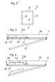
- the elevator comprises an elevator car 1 comprising a cabin box 2, which is illustrated in further details in Figure 2 .
- the cabin box is provided with a floor 3, a roof 4, walls 5 and preferably also at least one door (not shown) each of these delimiting an interior space 6 for receiving a load to be transported with the elevator car 1.
- the elevator comprises at least two vertically spaced apart landings 7, 8 between which the elevator car is arranged to travel vertically in a hoistway S.
- the elevator comprises a motor 9 connected to the car 1 in a force-transmitting manner.
- the motor 9 is connected to a stationary mounted drive wheel 14 engaging a hoisting roping 15 connected to the car.
- the rotation of the motor 9 causes rotation of the drive wheel 14 and thereby movement of the hoisting roping 15.
- the rotation of the motor 9 is transmitted to the car 1 via the drive wheel 14 and the hoisting roping 15. Accordingly, the movement of the car can be transmitted by controlling rotation of the motor 9.
- the motor 9 is arranged to be controlled with a control system 10, 11,11',11",11"',11"",11""'.
- the control system 10,11,11',11",11"',11"",11"' is provided with an automatic control mode and a manual control mode, in which automatic control mode the motor is arranged to be automatically controlled by the control system in response to calls from passengers to move the elevator car 1 automatically from one landing to another, e.g.
- the motor is arranged to be manually controllable to move the elevator car 1 any manually controllable distance upwards or downwards, i.e. a distance equal, longer or shorter than the distance between landings 7,8 of the elevator.
- the switching between these modes can be provided in a known manner, as it is well known to provide an elevator with an automatic control mode (i.e. the normal use mode) and a manual control mode (i.e. a service mode).
- the elevator comprises an operating unit 11,11',11",11"',11"",11""'.
- This operating unit 11,11',11",11"',111"",11”"' is mounted on the elevator car 1 and it comprises operating means 12,12',12",12"',12"",12""' operable manually by a user for said manual control, i.e. for inputting manual control commands.
- Said operating means 12,12',12",12"',12"",12""' preferably comprises a first (upwards) button, upon actuation of which the motor 9 is arranged to move the elevator car 1 upwards as long as the button is actuated, and a second (downwards) button upon actuation of which the motor 9 is arranged to move the elevator car 1 downwards as long as the button is actuated.
- the motor 9 is arranged to be manually controllable to move the elevator car 1 a manually controllable distance upwards or downwards;
- the operating unit 11,11',11",11"',11"",11""' is positioned such that the operating means 12,12',12",12"',12"",12""' thereof are operable by a user positioned inside said interior space 6 after removing a removable blockage.
- the blockage is provided for the purpose of delimiting access to the operating means 12,12',12",12"',12"",12""' to only those people who can remove the blockage, in practice to only those people who have been authorized.
- This function is provided for such that the car 1 comprises a blocking means 13,13',13",13"',13"",13""' operable by a user 14 positioned inside said interior space 6, the state of the blocking means being changeable between a blocking state and an unblocking state.
- the blocking means block operation of the operating means 12,12',12",12"',12"",12”"' for said manual control by a user positioned inside said interior space 6, and in the unblocking state the blocking means allow (i.e. they don't block) the operation of the operating means 12,12',12",12"',12"",12""' for said manual control by a user positioned inside said interior space 6.
- Both the operation of the blocking means 13,13',13",13"',13"",13""' and the operation of the operating means 12,12',12",12"',12"",12”"' (after removing said blockage) can be performed by a person positioned inside said interior space 6.
- the operating means 12,12',12",12"',12"",12""' are thereby bringable by operation of the blocking means (performed by a user positioned inside said interior space 6) to change their state from blocking state to said unblocking state, from a state wherein they are manually inoperable to a user positioned inside said interior space 6 to a state wherein they are manually operable to user positioned inside said interior space 6.
- said user is a maintenance person.
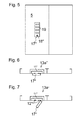
- FIGs 3, 4 and 5 each illustrate an embodiment, where said blocking means 13, 13', 13" comprise an openable housing 13a, 13a', 13a" inside which the operating means 12, 12', 12" are contained.
- said blocking state the housing is closed and blocks physical access to the operating means 12, 12', 12" and thereby the housing blocks physically also the operation of the operating means 12, 12', 12" for said manual control by a user positioned inside said interior space 6.
- the housing 13a, 13a', 13a" is open and physical access to the operating means is unblocked by said housing 13a, 13a', 13a", the housing 13a, 13a', 13a" thereby allowing operation of the operating means 12, 12', 12" for said manual control by a user positioned inside said interior space 6.
- the operating means 12, 12', 12" are thus unaccessible to said user positioned inside said interior space 6 unless the housing is opened.
- the housing 13a, 13a', 13a" comprises an openable cover 17, 17', 17", and the operating means 12, 12', 12" are behind the cover 17, 17', 17".
- the cover 17, 17', 17" is between the interior space 6 and the operating means 12, 12', 12".
- the cover 17, 17', 17" is movable between a closed position where it closes the housing 17, 17', 17" and blocks physical access into the housing 13a, 13a', 13a" and to the operating means 12, 12', 12" making them manually unoperable to said user, and an open position where physical access in the housing 13a, 13a', 13a" and to the operating means 12, 12', 12" is unblocked by said cover 17, 17', 17".
- the blocking means 13, 13', 13" further comprises a lock 18, 18', 18" for locking the blocking means 13, 13', 13" in a blocking state.
- the lock 18, 18', 18" is arranged to lock the housing 13a, 13a', 13a" in a closed state, which is preferably implemented such that the lock 18, 18', 18" is arranged to lock the cover 17, 17', 17" immovable.
- Said lock 18, 18', 18" is openable with a with a key, in particular with a triangular key. It is preferable, that the cover 17, 17', 17" is pivotally mounted (and thereby openable by pivoting movement), for example via hinges as illustrated in Figures 3-5 .
- the housing 13a, 13a', 13a" it is preferable that not only the operating means 12,12',12" but the complete operating unit 11, 11', 11" is inside the housing 13a, 13a', 13a".
- a space efficient solution can be provided which is easy to install. It is thus also easy to integrate several additional functions into the operating unit 11,11',11", such as a battery 21 for providing electric power for electrical devices mounted on the elevator car (e.g. for the car lights or the door operator) at least during power failures and/or an emergency communication device 22 for providing a communication from the car to a remote service center.
- the housing can have any other shape than illustrated.
- the operating unit 11,11', and thereby also its operating means 12,12' are mounted inside the roof 4, which roof 4 forms said housing 13a,13a'.
- the blocking means 13,13' can be changed to unblocking state by working in the interior space 6 below the housing 13a,13a'.
- the housing 13a,13a' is openable in these embodiments by moving the cover 17,17' downwards, in this case with a pivotal movement.
- the cover 17,17' is a lower face plate of the roof 4 limiting the interior space 6.
- the roof 4 further comprises an upper face plate 20, the operating unit 11,1" being positioned between the upper face plate 20 and the lower face plate 17,17'.
- FIG. 3 and 4 differ in that the operating unit 11 is in the embodiment of Figure 3 mounted stationary behind the cover 17 and in Figure 4 , the operating unit 11' is mounted on the cover 17' to move along with the cover 17' when it is opened.
- the Figures 3 and 4 illustrate with solid line the housing 13a,13a' in closed state and with broken line the housing housing 13a,13a' in opened state.
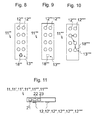
- the operating unit 11 ", and thereby also its operating means 12" are mounted inside the wall 5, which wall forms said housing 13a".
- the blocking means 13" can be changed to unblocking state by working in the interior space 6 below beside the housing 13a".
- the housing 13a,13a' is openable in these embodiments by moving the cover 17" sideways, in this case with a pivotal movement.
- the cover 17" is a face plate of the wall 5 limiting the interior space 6.
- the cover 17" is a panel used for receiving car calls from the passenger during normal use of the elevator, i.e. during the automatic control mode of the elevator, for which purpose the cover 17" comprises buttons 19 or alternatively a touch screen.
- Figures 8, 9 and 10 each illustrate an embodiment, where the operating means 12"', 12"", 12""' are formed by the buttons of a button panel mounted on the car 1 for being used in the automatic control mode for receiving car calls from a passenger.
- the blocking means 13"', 13"", 13""' in these cases, when in blocking state, block operation of the operating means 12"', 12"", 12""', for said manual control by a user positioned inside said interior space 6.
- the blocking means 13"', 13"", 13"' allow operation of the operating means 12"', 12"", 12"" for said manual control by a user positioned inside said interior space 6.
- the blocking means 13"', 13"", 13""' are in blocking state and when the elevator is in manual control mode the blocking means 13"', 13"", 13""' are in unblocking state. It is preferable, but not necessary, that the elevator is configured to receive car calls from a passenger (in response to which car calls the car is moved automatically from one landing to another) via these same buttons forming the operating means 12"', 12"", 12"" when the elevator is in automatic control mode.
- Figures 8, 9 and 10 show different types of blocking means.
- the blocking means 13"' comprises a mechanical lock 18"', in particular a triangular lock, openable with a mechanical key, in particular with a triangular key.
- the blocking means 13"" comprises an electronically actuatable lock 18"", in particular a lock openable with a RF - identification means such as an RF -tag.
- the opening of the lock is configured to change the blocking means into said unblocking state.
- the blocking means 13""' comprises a code lock 18""' openable by feeding a code via the button panel, in particular by pressing predefined buttons in a predefined order (illustrated with arrows).
- the opening of the lock 18""' is configured to change the blocking means into said unblocking state.
- the blocking means in particular the lock 18"',18"",18""' thereof, may comprise a processor (not shown) configured to control the state of the blocking means 13"',13"",13""' in response to operation thereof by a user.
- FIG 11 illustrates the operating unit 11,11',11",11"',11"",11”"', when functions additional to said manual control function are integrated into it.
- the operating unit 11,11',11",11"',11"",11”' comprises a battery 21 for providing electric power for electrical devices mounted on the elevator car (1), such as for lights as well as an emergency communication device 22.
- the operating unit 11,11',11",11"',11"",11”' may further comprise a control unit 23 for controlling a door drive (not shown) for controlling the door moving (electric) motor of the car door(s), which motor is connected to the door(s).
- the operating unit 11,11',11",11"',11"",11""' is at least partly, preferably completely, inside one of said floor 3, roof 4 and wall 5.
- the unit serves as a multipurpose-unit, and the installation of these functions can be provided simply and quickly.
- the overall solution thus provided is also space-efficient, as no room needs to be provided for the functions in several places, and the consumption of the overhead space between the roof of the cabin box 2 of car 1 and the roof of the hoistway S is minimized.
- the elevator control system is such that it comprises a drive unit 10 connected to the motor 9, which drive unit 10 in said automatic control mode automatically controls the motor 9 in response to calls from passengers to move the elevator car 1 automatically from one landing to another.
- the drive unit 10 is provided with a frequency converter regulating the supply of electricity to the motor 9, as well as one or more processors configured to set a speed reference according to which the frequency converter is configured to regulate the supply of electricity to the motor 9.
- Said one or more processors are preferably configured to set the speed reference according to an algorithm stored in a memory of the drive unit 10.
- the operating unit 11,11',11",11"',11"",11""' is preferably arranged to communicate with the drive unit 10 during the manual control mode.
- said one or more processor which are preferably microprocessors, are configured to set the speed reference, which provides a car speed which is lower than the nominal speed of the elevator.
- the manual control is well suitable for safe maintenance drive of the elevator.
- said one or more processor also is able to set the speed reference to zero independent of car position, which is carried out in response to a predefined change in signal from the operating unit 11,11',11",11"',11"",11""' which change is associated with zero speed.
- the car 1 can be stopped independent of car position.
- said operating means 12,12',12",12"',12"",12""' comprises a first (upwards) button, upon actuation of which the motor 9 is arranged to move the elevator car 1 upwards as long as the button is actuated, and a second (downwards) button upon actuation of which the motor 9 is arranged to move the elevator car 1 downwards as long as the button is actuated.
- first (upwards) button upon actuation of which the motor 9 is arranged to move the elevator car 1 upwards as long as the button is actuated
- a second (downwards) button upon actuation of which the motor 9 is arranged to move the elevator car 1 downwards as long as the button is actuated.
Landscapes
- Engineering & Computer Science (AREA)
- Automation & Control Theory (AREA)
- Cage And Drive Apparatuses For Elevators (AREA)
- Elevator Control (AREA)
- Maintenance And Inspection Apparatuses For Elevators (AREA)
Abstract
Description
- The invention relates to an elevator, in particular to the manual control function of an elevator. The elevator is, in particular, meant for transporting passengers.
- Elevators are normally provided with an elevator car, arranged to be moved with an electric motor. This motor for moving the elevator car is connected to the car in a force-transmitting manner. Typically, the motor is connected to a stationary mounted drive wheel engaging a hoisting roping connected to the car. The rotation of the motor causes rotation of the drive wheel and thereby movement of the hoisting roping. Thus the rotation of the motor is transmitted to the car via the drive wheel and the roping. Accordingly, the movement of the car can be transmitted by controlling rotation of the motor. Also other types of elevators are known, which utilize a motor for producing the movement of the car. Modern elevators are typically provided with a control system, which can be switched between an automatic control mode and a manual control mode. When in automatic control mode, the motor of the elevator is arranged to be automatically controlled by the control system in response to calls from passengers to move the elevator car automatically from one landing to another. When in the manual control mode, the motor is arranged to be manually controllable to move the elevator car a manually controllable distance upwards or downwards, i.e. also a distance other than the vertical distance between any two landings of the elevator, in particular also a distance shorter than the vertical distance between consecutive landings. With the manual control mode, the elevator can be controlled by a maintenance person to move and park the car to practically any position in the hoistway, also to positions between consecutive landings. When in manual control mode, the elevator speed is typically substantially lower than the nominal speed of the elevator car. Indeed, the manual control mode is normally provided so as to serves as a service drive mode. For the purpose of the manual control, the elevator is provided with an operating unit for said manual control, which is mounted on the car roof, and accessible only by entering the hoistway, climbing on the car roof and operating it while standing on the car roof. The operating unit comprises operating means, which are operable manually by a user. A problem with the know solutions is that the manual control necessitates access to the roof, which may in some cases be difficult to arrange. Also, staying on the car roof while the car is moving may cause accidents if the person slips of drives the car too close to the end of the hoistway. For this purpose, additional safety devices have been installed in the hoistway, such as additional safety limits for maintenance-time car movement.
- The object of the invention is, inter alia, to solve previously described drawbacks of known solutions and problems discussed later in the description of the invention. The object of the invention is to introduce an elevator, wherein the safety of the user is simply ensured during manual control of the elevator. The object is further that said manual control can be allowed for authorized users only. Embodiments are presented wherein these objects are facilitated in a space-efficient manner.
- It is brought forward a new elevator comprising an elevator car comprising a cabin box provided with a floor, a roof, walls and preferably also door(s) each delimiting an interior space for receiving a load to be transported with the elevator car. The elevator further comprises at least two landings, a motor for moving the elevator car and a control system for controlling the motor, wherein the control system is provided with an automatic control mode and a manual control mode, in which automatic control mode the motor is arranged to be automatically controlled by the control system in response to calls from passengers to move the elevator car automatically from one landing to another, and in which manual control mode the motor is arranged to be manually controllable to move the elevator car a manually controllable distance upwards or downwards. The elevator further comprises an operating unit for said manual control, the operating unit being mounted on the elevator car and comprising operating means operable manually by a user for said manual control. The car comprises a blocking means operable by a user positioned inside said interior space, the state of the blocking means being changeable between a blocking state and an unblocking state, in which blocking state the blocking means block operation of the operating means for said manual control by a user positioned inside said interior space, and in which unblocking state the blocking means allow operation of the operating means for said manual control by a user positioned inside said interior space, the operating unit being positioned such that the operating means thereof are operable by a user positioned inside said interior space after operation of the blocking means to change their state from blocking state to said unblocking state. The operating means are thus bringable from manually inoperable state to a manually operable state by a user positioned inside said interior space by operation of the blocking means to change their state from blocking state to said unblocking state. The operating means can thus be operated in safe conditions, and operability of them is limited to only those people who can remove the blockage, in practice to only those people who have been authorized to suitable means.
- In a preferred embodiment blocking means comprises a lock for locking the blocking means in a blocking state. Thereby the accessibility to the operating means can simply be limited to those authorized users only who have been provided a means for opening the lock.
- In a preferred embodiment the blocking means comprise an openable housing inside which the operating means are, and in said blocking state the housing is closed and blocks physical access to the operating means and thereby the operation of the operating means for said manual control by a user positioned inside said interior space, and in said unblocking state the housing is open and physical access to the operating means is unblocked by said housing, thereby allowing operation of the operating means for said manual control by a user positioned inside said interior space. The operating means can thus be made unaccessible to said user positioned inside said interior space unless the housing is opened. Thus a physical blockage limiting access to the operating means is simply provided. In a preferred embodiment the aforementioned lock is arranged to lock the housing in a closed state.
- In a preferred embodiment the housing comprises an openable cover, the cover is movable between an closed position where it closes the housing and blocks physical access in to the housing and to the operating means making them manually unoperable to said user, and an open position where physical access in the housing and to the operating means is unblocked by said cover. In particular, the operating means are behind the cover, whereby the cover is between the interior space and the operating means. Thus a physical blockage limiting access to the operating means is simply provided. Preferably, the aforementioned lock is arranged to lock the cover immovable. Preferably, the cover is pivotally mounted, and thereby openable by pivoting movement. In particular, the cover may be mounted by hinges.
- In a preferred embodiment the aforementioned lock is openable with a key, in particular with a mechanical key, an electronic key, or a code key. Thus, beneficial alternatives for providing authorization are provided.
- In a preferred embodiment the operating means are inside one of said floor, roof and walls. The overall solution thus provided is space-efficient.
- In a preferred embodiment the operating unit is at least partly, but preferably completely inside one of said floor, roof and walls. The overall solution thus provided is also space-efficient, as no separate room needs to be provided for the functions contained in the operating unit, and the consumption of the overhead space between the roof of the cabin box of car and the roof of the hoistway is spared, for instance.
- In a preferred embodiment the operating unit comprises a battery for providing electric power for electrical devices mounted on the elevator car, such as for lights and/or emergency communication device. Thus, the unit serves as a multipurpose-unit, and the installation of these functions can be provided simply and quickly.
- In a preferred embodiment said operating means comprises a first button, upon actuation of which the motor is arranged to move the elevator car upwards as long as the button is actuated e.g. by pressing, and a second button upon actuation of which the motor is arranged to move the elevator car downwards as long as the button is actuated, e.g. by pressing. Thus, the motor is simply arranged to be manually controllable to move the elevator car a manually controllable distance upwards or downwards. The motor is arranged to stop when said actuation ceases.
- In a preferred embodiment the operating means are formed by buttons of a button panel mounted on the car for being used in the automatic control mode for receiving car calls from a passenger. Also in this case, the blocking means, when in blocking state, block operation of said operating means formed by buttons, for said manual control by a user positioned inside said interior space and in the unblocking state the blocking means allow operation of the operating means formed by buttons for said manual control by a user positioned inside said interior space. It is preferable, but not necessary, that the elevator is in automatic control mode configured to receive car calls from a passenger (in response to which car calls the car is moved automatically from one landing to another) via these same buttons forming the operating means. Also in this case it is preferable that the blocking means comprises a lock the opening of which is configured to change the blocking means into said unblocking state. This opening preferably also changes the state of the elevator from automatic control mode to the manual control mode.
- The elevator as describe anywhere above is preferably, but not necessarily, installed inside a building. The car is preferably arranged to serve two or more landings. The car preferably is arranged to respond to calls from landing(s) and/or destination commands from inside the car so as to serve persons on the landing(s) and/or inside the elevator car. Preferably, the car has an interior space suitable for receiving a load in the form of a passenger or passengers.
- In the following, the present invention will be described in more detail by way of example and with reference to the attached drawings, in which
-
Figure 1 illustrates an elevator according to an embodiment of the invention. -
Figure 2 illustrates the cabin box ofFigure 1 in further details. -
Figure 3 illustrates the operating unit in its position according to a first embodiment as viewed in horizontal direction. -
Figure 4 illustrates the operating unit in its position according to a second embodiment as viewed in horizontal direction. -
Figure 5 illustrates the operating unit in its position according to a third embodiment as viewed from inside the interior space in horizontal direction. -
Figure 6 illustrates the operating unit in its position according to a third embodiment as viewed in vertical direction when the housing is closed. -
Figure 7 illustrates the operating unit in its position according to a third embodiment as viewed in vertical direction when the housing is open. -
Figure 8 illustrates the operating unit in its position according to a fourth embodiment as viewed from inside the interior space in horizontal direction. -
Figure 9 illustrates the operating unit in its position according to a fifth embodiment as viewed from inside the interior space in horizontal direction. -
Figure 10 illustrates the operating unit in its position according to a sixth embodiment as viewed from inside the interior space in horizontal direction. -
Figure 11 illustrates a side view of the operating unit as such according.to a preferred embodiment. -
Figure 1 illustrates an elevator according to a preferred embodiment. The elevator comprises an elevator car 1 comprising acabin box 2, which is illustrated in further details inFigure 2 . The cabin box is provided with afloor 3, aroof 4,walls 5 and preferably also at least one door (not shown) each of these delimiting aninterior space 6 for receiving a load to be transported with the elevator car 1. The elevator comprises at least two vertically spaced apartlandings motor 9 connected to the car 1 in a force-transmitting manner. In this embodiment, themotor 9 is connected to a stationarymounted drive wheel 14 engaging a hoistingroping 15 connected to the car. The rotation of themotor 9 causes rotation of thedrive wheel 14 and thereby movement of the hoistingroping 15. Thus the rotation of themotor 9 is transmitted to the car 1 via thedrive wheel 14 and the hoistingroping 15. Accordingly, the movement of the car can be transmitted by controlling rotation of themotor 9. Themotor 9 is arranged to be controlled with acontrol system control system landings unit unit - Said operating means 12,12',12",12"',12"",12""' preferably comprises a first (upwards) button, upon actuation of which the
motor 9 is arranged to move the elevator car 1 upwards as long as the button is actuated, and a second (downwards) button upon actuation of which themotor 9 is arranged to move the elevator car 1 downwards as long as the button is actuated. Thus, themotor 9 is arranged to be manually controllable to move the elevator car 1 a manually controllable distance upwards or downwards; - The operating
unit interior space 6 after removing a removable blockage. The blockage is provided for the purpose of delimiting access to the operating means 12,12',12",12"',12"",12""' to only those people who can remove the blockage, in practice to only those people who have been authorized. This function is provided for such that the car 1 comprises a blocking means 13,13',13",13"',13"",13""' operable by auser 14 positioned inside saidinterior space 6, the state of the blocking means being changeable between a blocking state and an unblocking state. In the blocking state the blocking means block operation of the operating means 12,12',12",12"',12"",12""' for said manual control by a user positioned inside saidinterior space 6, and in the unblocking state the blocking means allow (i.e. they don't block) the operation of the operating means 12,12',12",12"',12"",12""' for said manual control by a user positioned inside saidinterior space 6. Both the operation of the blocking means 13,13',13",13"',13"",13""' and the operation of the operating means 12,12',12",12"',12"",12""' (after removing said blockage) can be performed by a person positioned inside saidinterior space 6. The operating means 12,12',12",12"',12"",12""' are thereby bringable by operation of the blocking means (performed by a user positioned inside said interior space 6) to change their state from blocking state to said unblocking state, from a state wherein they are manually inoperable to a user positioned inside saidinterior space 6 to a state wherein they are manually operable to user positioned inside saidinterior space 6. In the preferred embodiments said user is a maintenance person. -
Figures 3, 4 and5 each illustrate an embodiment, where said blocking means 13, 13', 13" comprise anopenable housing interior space 6. In said unblocking state thehousing housing housing interior space 6. The operating means 12, 12', 12"are thus unaccessible to said user positioned inside saidinterior space 6 unless the housing is opened. In particular, thehousing openable cover cover cover interior space 6 and the operating means 12, 12', 12". In the preferred embodiment, thecover housing housing housing cover - Preferably, the blocking means 13, 13', 13" further comprises a
lock lock housing lock cover lock cover Figures 3-5 . As further illustrated, it is preferable that not only the operating means 12,12',12" but thecomplete operating unit housing unit battery 21 for providing electric power for electrical devices mounted on the elevator car (e.g. for the car lights or the door operator) at least during power failures and/or anemergency communication device 22 for providing a communication from the car to a remote service center. It should be appreciated that the housing can have any other shape than illustrated. - In the embodiments illustrated in
Figures 3 and 4 , the operatingunit 11,11', and thereby also its operating means 12,12' are mounted inside theroof 4, whichroof 4 forms saidhousing interior space 6 below thehousing housing cover 17,17' downwards, in this case with a pivotal movement. Thecover 17,17' is a lower face plate of theroof 4 limiting theinterior space 6. Theroof 4 further comprises anupper face plate 20, the operatingunit 11,1" being positioned between theupper face plate 20 and thelower face plate 17,17'. The embodiments ofFigure 3 and 4 differ in that the operatingunit 11 is in the embodiment ofFigure 3 mounted stationary behind thecover 17 and inFigure 4 , the operating unit 11' is mounted on the cover 17' to move along with the cover 17' when it is opened. TheFigures 3 and 4 illustrate with solid line thehousing housing housing - In the embodiment illustrated in
Figures 6 and 7 , the operatingunit 11 ", and thereby also its operating means 12" are mounted inside thewall 5, which wall forms saidhousing 13a". The blocking means 13" can be changed to unblocking state by working in theinterior space 6 below beside thehousing 13a". Thehousing cover 17" sideways, in this case with a pivotal movement. Thecover 17" is a face plate of thewall 5 limiting theinterior space 6. In the preferred embodiment, thecover 17" is a panel used for receiving car calls from the passenger during normal use of the elevator, i.e. during the automatic control mode of the elevator, for which purpose thecover 17" comprisesbuttons 19 or alternatively a touch screen. -
Figures 8, 9 and 10 each illustrate an embodiment, where the operating means 12"', 12"", 12""' are formed by the buttons of a button panel mounted on the car 1 for being used in the automatic control mode for receiving car calls from a passenger. The blocking means 13"', 13"", 13""' in these cases, when in blocking state, block operation of the operating means 12"', 12"", 12""', for said manual control by a user positioned inside saidinterior space 6. In the unblocking state the blocking means 13"', 13"", 13""' allow operation of the operating means 12"', 12"", 12"" for said manual control by a user positioned inside saidinterior space 6. When the elevator is in automatic control mode, the blocking means 13"', 13"", 13""' are in blocking state and when the elevator is in manual control mode the blocking means 13"', 13"", 13""' are in unblocking state. It is preferable, but not necessary, that the elevator is configured to receive car calls from a passenger (in response to which car calls the car is moved automatically from one landing to another) via these same buttons forming the operating means 12"', 12"", 12"" when the elevator is in automatic control mode.Figures 8, 9 and 10 show different types of blocking means. In the embodiment illustrated inFigure 8 the blocking means 13"' comprises amechanical lock 18"', in particular a triangular lock, openable with a mechanical key, in particular with a triangular key. The opening of the lock is configured to change the blocking means into said unblocking state. In embodiment illustrated inFigure 9 the blocking means 13"" comprises an electronicallyactuatable lock 18"", in particular a lock openable with a RF - identification means such as an RF -tag. The opening of the lock is configured to change the blocking means into said unblocking state. In embodiment illustrated inFigure 10 the blocking means 13""' comprises acode lock 18""' openable by feeding a code via the button panel, in particular by pressing predefined buttons in a predefined order (illustrated with arrows). The opening of thelock 18""' is configured to change the blocking means into said unblocking state. In any of the embodiments ofFigures 8-10 , the blocking means, in particular thelock 18"',18"",18""' thereof, may comprise a processor (not shown) configured to control the state of the blocking means 13"',13"",13""' in response to operation thereof by a user. -
Figure 11 illustrates the operatingunit unit battery 21 for providing electric power for electrical devices mounted on the elevator car (1), such as for lights as well as anemergency communication device 22. The operatingunit control unit 23 for controlling a door drive (not shown) for controlling the door moving (electric) motor of the car door(s), which motor is connected to the door(s). In the case wherein one or more of said additional functions are integrated into the operating unit it is especially beneficial that the operatingunit floor 3,roof 4 andwall 5. Thus, the unit serves as a multipurpose-unit, and the installation of these functions can be provided simply and quickly. The overall solution thus provided is also space-efficient, as no room needs to be provided for the functions in several places, and the consumption of the overhead space between the roof of thecabin box 2 of car 1 and the roof of the hoistway S is minimized. - It is preferable that, as illustrated in
Figure 1 , the elevator control system is such that it comprises adrive unit 10 connected to themotor 9, which driveunit 10 in said automatic control mode automatically controls themotor 9 in response to calls from passengers to move the elevator car 1 automatically from one landing to another. For this purpose, thedrive unit 10 is provided with a frequency converter regulating the supply of electricity to themotor 9, as well as one or more processors configured to set a speed reference according to which the frequency converter is configured to regulate the supply of electricity to themotor 9. Said one or more processors are preferably configured to set the speed reference according to an algorithm stored in a memory of thedrive unit 10. The operatingunit drive unit 10 during the manual control mode. There may be, for instance a wired or wireless data transfer bus (as in theFigure 1 ) for transmitting a control signal s between them. A control signal s carrying a control command manually inputted via the operating means 12,12',12",12"',12"",12""'by a user positioned inside saidinterior space 6, can thereby be transmitted from the operatingunit drive unit 10. During the manual control mode, said one or more processor, which are preferably microprocessors, are configured to set the speed reference, which provides a car speed which is lower than the nominal speed of the elevator. Thus, the manual control is well suitable for safe maintenance drive of the elevator. During the manual control mode, said one or more processor also is able to set the speed reference to zero independent of car position, which is carried out in response to a predefined change in signal from the operatingunit motor 9 is arranged to move the elevator car 1 upwards as long as the button is actuated, and a second (downwards) button upon actuation of which themotor 9 is arranged to move the elevator car 1 downwards as long as the button is actuated. The details in this paragraph describe how the automatic control mode and manual control mode are provided in a preferred embodiment. However, in the field of elevator technology also alternative ways for providing the automatic control mode and the manual control mode are known, which could alternatively be utilized in combination with the specific solutions related to the means for blocking access to the operatingunit - It is to be understood that the above description and the accompanying Figures are only intended to illustrate the present invention. It will be apparent to a person skilled in the art that the inventive concept can be implemented in various ways. The invention and its embodiments are not limited to the examples described above but may vary within the scope of the claims.
Claims (12)
- An elevator comprising
an elevator car (1) comprising a cabin box (2) provided with a floor (3), a roof (4), walls (5) and preferably also door(s) each delimiting an interior space (6) for receiving a load to be transported with the elevator car (1);
at least two landings (7,8);
a motor (9) for moving the elevator car (1);
a control system (10, 11,11',11",11"',11"",11""') for controlling the motor (9);
wherein the control system (10, 11-11""') is provided with an automatic control mode and a manual control mode, in which automatic control mode the motor (9) is arranged to be automatically controlled by the control system (10, 11-11""') to move the elevator car (1) automatically from one landing (7) to another (8), and in which manual control mode the motor (9) is arranged to be manually controllable to move the elevator car (1) a manually controllable distance upwards or downwards;
an operating unit (11,11',11",11"',11"",11""') for said manual control, the operating unit (11,11',11",11"',11"",11""') being mounted on the elevator car (1) and comprising operating means (12,12',12",12"',12"",12""') operable manually by a user for said manual control,
characterized in that the car (1) comprises a blocking means (13,13',13",13"',13"",13""') operable by a user positioned inside said interior space (6), the state of the blocking means (13,13',13",13"',13"",13""') being changeable between a blocking state and an unblocking state,
in which blocking state the blocking means (13,13',13",13"',13"",13""') block operation of the operating means (12,12',12",12"',12"",12""') for said manual control by a user (14) positioned inside said interior space (6), and
in which unblocking state the blocking means (13,13',13",13"',13"",13""') allow operation of the operating means (12,12',12",12"',12"",12""') for said manual control by a user positioned inside said interior space (6),
the operating unit (11) being positioned such that the operating means (12,12',12",12"',12"",12""') thereof are operable by a user positioned inside said interior space (6) after operation of the blocking means (13,13',13",13"',13"",13""') to change their state from blocking state to said unblocking state. - An elevator according to claim 1, characterized in that the blocking means (13,13',13") comprise an openable housing (13a, 13a', 13a") inside which the operating means (12, 12', 12") are, and in said blocking state the housing (13a, 13a', 13a") is closed and blocks physical access to the operating means (12, 12', 12") and thereby the operation of the operating means (12, 12', 12") for said manual control by a user (14) positioned inside said interior space (6), and in said unblocking state the housing (13a, 13a', 13a") is open and physical access to the operating means (12, 12', 12") is unblocked by said housing (13a, 13a', 13a") thereby allowing operation of the operating means (12, 12', 12") for said manual control by a user (14) positioned inside said interior space (6).
- An elevator according to claim 2, characterized in that the housing (13a, 13a', 13a") comprises an openable cover (17, 17', 17"), which cover (17, 17', 17") is movable between a closed position where it closes the housing (13a, 13a', 13a") and blocks physical access into the housing (13a, 13a', 13a") and to the operating means (13,13',13") making them manually unoperable to said user, and an open position where physical access into the housing (13a, 13a', 13a") and to the operating means (13,13',13") is unblocked by said cover (17, 17', 17").
- An elevator according to any of the preceding claims, characterized in that the blocking means (13-13""') comprises a lock (18-18""') for locking the blocking means (13-13""') in a blocking state.
- An elevator according to any of the preceding claims 2-4, characterized in that the blocking means (13-13""') comprises a lock (18-18"), which is arranged to lock the housing (13a, 13a', 13a") in a closed state.
- An elevator according to claim 3, characterized in that blocking means comprises a lock (18-18") for locking the cover (17, 17', 17") immovable.
- An elevator according to any of the preceding claims 4-6, characterized in that said lock (18-18""') is openable with a key, in particular with a mechanical key, an electronic key, or a code key.
- An elevator according to any of the preceding claims, characterized in that the operating means (12-12""') are inside one of said floor (3), roof (4) and wall(s) (5).
- An elevator according to any of the preceding claims, characterized in that the operating unit (11,11',11") is at least partly, preferably completely inside one of said floor (3), roof (4) and wall(s) (5).
- An elevator according to any of the preceding claims, characterized in that the operating unit (11-11 ""') comprises a battery (21) for providing electric power for electrical devices mounted on the elevator car (1), such as for lights and/or emergency communication device (22).
- An elevator according to any of the preceding claims, characterized in that said operating means (12-12""') comprises a first button, upon actuation of which the motor (9) is arranged to move the elevator car (1) upwards as long as the button is actuated, and a second button upon actuation of which the motor (9) is arranged to move the elevator car (1) downwards as long as the button is actuated.
- An elevator according to any of the preceding claims, characterized in that the operating means (12"', 12"", 12""') are formed by buttons of a button panel mounted on the car (1) for being used in the automatic control mode for receiving car calls from a passenger.
Priority Applications (3)
| Application Number | Priority Date | Filing Date | Title |
|---|---|---|---|
| EP13184758.4A EP2848570B1 (en) | 2013-09-17 | 2013-09-17 | An elevator |
| US14/448,245 US10322907B2 (en) | 2013-09-17 | 2014-07-31 | Elevator |
| CN201410425728.9A CN104444717B (en) | 2013-09-17 | 2014-08-26 | Elevator |
Applications Claiming Priority (1)
| Application Number | Priority Date | Filing Date | Title |
|---|---|---|---|
| EP13184758.4A EP2848570B1 (en) | 2013-09-17 | 2013-09-17 | An elevator |
Publications (2)
| Publication Number | Publication Date |
|---|---|
| EP2848570A1 true EP2848570A1 (en) | 2015-03-18 |
| EP2848570B1 EP2848570B1 (en) | 2016-08-10 |
Family
ID=49209265
Family Applications (1)
| Application Number | Title | Priority Date | Filing Date |
|---|---|---|---|
| EP13184758.4A Active EP2848570B1 (en) | 2013-09-17 | 2013-09-17 | An elevator |
Country Status (3)
| Country | Link |
|---|---|
| US (1) | US10322907B2 (en) |
| EP (1) | EP2848570B1 (en) |
| CN (1) | CN104444717B (en) |
Cited By (1)
| Publication number | Priority date | Publication date | Assignee | Title |
|---|---|---|---|---|
| IT201900006919A1 (en) * | 2019-05-16 | 2020-11-16 | Lifting Italia S R L | LIFTING PLATFORM AND LIFTING SYSTEM INCLUDING THE LIFTING PLATFORM |
Families Citing this family (7)
| Publication number | Priority date | Publication date | Assignee | Title |
|---|---|---|---|---|
| BR112013024033A2 (en) * | 2011-03-21 | 2017-06-27 | Inventio Ag | elevator having minimum elevator shaft depth and a permanent protective space |
| CN106573758B (en) * | 2014-08-18 | 2019-11-15 | 奥的斯电梯公司 | Embedded energy storage for driving vehicles and auxiliary systems |
| EP3124418A1 (en) * | 2015-07-28 | 2017-02-01 | Inventio AG | Elevator controller with wireless access point |
| JP6643914B2 (en) * | 2016-02-17 | 2020-02-12 | 三菱電機ビルテクノサービス株式会社 | elevator |
| EP3569542B1 (en) * | 2018-05-15 | 2021-06-30 | Otis Elevator Company | Wireless communication in an elevator system |
| EP3730442B1 (en) * | 2019-04-26 | 2025-02-12 | KONE Corporation | Mobile operating unit, elevator and method |
| ES2907860T3 (en) * | 2019-09-26 | 2022-04-26 | Otis Elevator Co | Motion control of an elevator car of an elevator system |
Citations (4)
| Publication number | Priority date | Publication date | Assignee | Title |
|---|---|---|---|---|
| JPS6381082U (en) * | 1986-11-14 | 1988-05-28 | ||
| US6302240B1 (en) * | 2000-06-19 | 2001-10-16 | Kuei-Tang Shih | Auxiliary safety lift device for the cab of an elevator |
| US20080217114A1 (en) * | 2007-03-09 | 2008-09-11 | Hugo Felder | Emergency device for installing in an elevator car of an elevator installation |
| JP2013018574A (en) * | 2011-07-08 | 2013-01-31 | Mitsubishi Electric Corp | Operation panel of elevator car |
Family Cites Families (15)
| Publication number | Priority date | Publication date | Assignee | Title |
|---|---|---|---|---|
| US4004655A (en) * | 1975-08-28 | 1977-01-25 | Westinghouse Electric Corporation | Elevator system including door operator having an enclosure which forms track for door rollers |
| JPS6381082A (en) | 1986-09-24 | 1988-04-11 | Seiko Instr & Electronics Ltd | Laser multicolored recording method |
| JPH03143889A (en) * | 1989-10-27 | 1991-06-19 | Mitsubishi Electric Corp | Device for operating elevator during maintenance |
| JPH07206301A (en) * | 1994-01-18 | 1995-08-08 | Mitsubishi Denki Bill Techno Service Kk | Elevator |
| FI112199B (en) * | 1994-10-21 | 2003-11-14 | Kone Corp | Freely programmable control panel for elevator basket |
| US5749443A (en) * | 1995-05-12 | 1998-05-12 | Otis Elevator Company | Elevator based security system |
| US5721403A (en) * | 1996-03-29 | 1998-02-24 | Otis Elevator Company | Selective circuit bypass for elevator system |
| KR100435987B1 (en) * | 1999-10-07 | 2004-06-12 | 미쓰비시덴키 가부시키가이샤 | Elevator maintenance/operation apparatus |
| FR2811971B1 (en) * | 2000-07-21 | 2002-12-13 | Sodimas | ELEVATOR INSTALLATION WITH A REDUCED HEIGHT UPPER LEVEL |
| US6630886B2 (en) * | 2001-07-10 | 2003-10-07 | Otis Elevator Company | Top of elevator car inspection station with alarm |
| US6948592B2 (en) * | 2002-09-23 | 2005-09-27 | Medtronic Emergency Response Systems, Inc. | Elevators equipped with emergency medical devices |
| EP1641699B1 (en) * | 2003-07-03 | 2021-05-26 | Inventio AG | Elevator with car electrics integrated in the car roof |
| US7258202B1 (en) * | 2004-05-10 | 2007-08-21 | Inventio Ag | Creation of temporary safety spaces for elevators |
| SG139660A1 (en) * | 2006-07-26 | 2008-02-29 | Inventio Ag | Method of controlling access to an elevator car |
| JP4906494B2 (en) | 2006-12-20 | 2012-03-28 | 株式会社日立製作所 | Elevator car operation panel |
-
2013
- 2013-09-17 EP EP13184758.4A patent/EP2848570B1/en active Active
-
2014
- 2014-07-31 US US14/448,245 patent/US10322907B2/en active Active
- 2014-08-26 CN CN201410425728.9A patent/CN104444717B/en active Active
Patent Citations (4)
| Publication number | Priority date | Publication date | Assignee | Title |
|---|---|---|---|---|
| JPS6381082U (en) * | 1986-11-14 | 1988-05-28 | ||
| US6302240B1 (en) * | 2000-06-19 | 2001-10-16 | Kuei-Tang Shih | Auxiliary safety lift device for the cab of an elevator |
| US20080217114A1 (en) * | 2007-03-09 | 2008-09-11 | Hugo Felder | Emergency device for installing in an elevator car of an elevator installation |
| JP2013018574A (en) * | 2011-07-08 | 2013-01-31 | Mitsubishi Electric Corp | Operation panel of elevator car |
Cited By (2)
| Publication number | Priority date | Publication date | Assignee | Title |
|---|---|---|---|---|
| IT201900006919A1 (en) * | 2019-05-16 | 2020-11-16 | Lifting Italia S R L | LIFTING PLATFORM AND LIFTING SYSTEM INCLUDING THE LIFTING PLATFORM |
| EP3738914A1 (en) | 2019-05-16 | 2020-11-18 | Lifting Italia S.r.l. | Lift platform and home lift comprising the lift platform |
Also Published As
| Publication number | Publication date |
|---|---|
| US20150075918A1 (en) | 2015-03-19 |
| US10322907B2 (en) | 2019-06-18 |
| EP2848570B1 (en) | 2016-08-10 |
| CN104444717A (en) | 2015-03-25 |
| CN104444717B (en) | 2019-03-12 |
Similar Documents
| Publication | Publication Date | Title |
|---|---|---|
| US10322907B2 (en) | Elevator | |
| US10001861B2 (en) | Elevator with maintenance opening in the car floor | |
| US9630804B2 (en) | Method for providing well access in an elevator | |
| EP3231758B1 (en) | Handrail used to open and close elevator car panels | |
| EP2927174B1 (en) | Elevator system | |
| CN103596866B (en) | There is the elevator of the car that can travel under service mode | |
| BRPI0701523A2 (en) | process for adjusting floor allocations, a large number of control units, an elevator | |
| JP5554154B2 (en) | Elevator remote control system | |
| US20190389695A1 (en) | Elevator system | |
| EP3517478B1 (en) | Elevator component access cabinet | |
| JPWO2005102900A1 (en) | Elevator door unlocking device | |
| US6847292B2 (en) | Method and device for remote unlocking of an access door of a building with an elevator | |
| CN204111088U (en) | The emergency call apparatus of elevator | |
| EP3929133A1 (en) | Elevator cars | |
| JP2017030955A (en) | Elevator | |
| EP1775250B1 (en) | Door device of elevator | |
| JP2011098788A (en) | Elevator system | |
| CN103270230B (en) | vertical stairs | |
| EP3288883B1 (en) | Car operation panel of an elevator system | |
| CN100519389C (en) | Control device of elevator | |
| WO2012025992A1 (en) | Elevator device | |
| EP4650312A1 (en) | Method of providing access to at least one component of an elevator system and elevator system | |
| JPH02225278A (en) | Controller for elevator | |
| KR101293035B1 (en) | Inspection position automatic landing system of elevator car and the control method thereof | |
| JP4420187B2 (en) | Elevator equipment for seismic isolation buildings |
Legal Events
| Date | Code | Title | Description |
|---|---|---|---|
| PUAI | Public reference made under article 153(3) epc to a published international application that has entered the european phase |
Free format text: ORIGINAL CODE: 0009012 |
|
| 17P | Request for examination filed |
Effective date: 20130917 |
|
| AK | Designated contracting states |
Kind code of ref document: A1 Designated state(s): AL AT BE BG CH CY CZ DE DK EE ES FI FR GB GR HR HU IE IS IT LI LT LU LV MC MK MT NL NO PL PT RO RS SE SI SK SM TR |
|
| AX | Request for extension of the european patent |
Extension state: BA ME |
|
| R17P | Request for examination filed (corrected) |
Effective date: 20150813 |
|
| RBV | Designated contracting states (corrected) |
Designated state(s): AL AT BE BG CH CY CZ DE DK EE ES FI FR GB GR HR HU IE IS IT LI LT LU LV MC MK MT NL NO PL PT RO RS SE SI SK SM TR |
|
| REG | Reference to a national code |
Ref country code: DE Ref legal event code: R079 Ref document number: 602013010222 Country of ref document: DE Free format text: PREVIOUS MAIN CLASS: B66B0001460000 Ipc: B66B0005000000 |
|
| GRAP | Despatch of communication of intention to grant a patent |
Free format text: ORIGINAL CODE: EPIDOSNIGR1 |
|
| RAP1 | Party data changed (applicant data changed or rights of an application transferred) |
Owner name: KONE CORPORATION |
|
| RIC1 | Information provided on ipc code assigned before grant |
Ipc: B66B 1/46 20060101ALI20151027BHEP Ipc: B66B 11/02 20060101ALI20151027BHEP Ipc: B66B 5/00 20060101AFI20151027BHEP |
|
| INTG | Intention to grant announced |
Effective date: 20151110 |
|
| INTG | Intention to grant announced |
Effective date: 20160303 |
|
| GRAS | Grant fee paid |
Free format text: ORIGINAL CODE: EPIDOSNIGR3 |
|
| GRAA | (expected) grant |
Free format text: ORIGINAL CODE: 0009210 |
|
| AK | Designated contracting states |
Kind code of ref document: B1 Designated state(s): AL AT BE BG CH CY CZ DE DK EE ES FI FR GB GR HR HU IE IS IT LI LT LU LV MC MK MT NL NO PL PT RO RS SE SI SK SM TR |
|
| REG | Reference to a national code |
Ref country code: GB Ref legal event code: FG4D |
|
| REG | Reference to a national code |
Ref country code: CH Ref legal event code: EP Ref country code: AT Ref legal event code: REF Ref document number: 818798 Country of ref document: AT Kind code of ref document: T Effective date: 20160815 |
|
| REG | Reference to a national code |
Ref country code: IE Ref legal event code: FG4D |
|
| REG | Reference to a national code |
Ref country code: FR Ref legal event code: PLFP Year of fee payment: 4 |
|
| REG | Reference to a national code |
Ref country code: DE Ref legal event code: R096 Ref document number: 602013010222 Country of ref document: DE |
|
| REG | Reference to a national code |
Ref country code: LT Ref legal event code: MG4D |
|
| REG | Reference to a national code |
Ref country code: NL Ref legal event code: MP Effective date: 20160810 |
|
| REG | Reference to a national code |
Ref country code: AT Ref legal event code: MK05 Ref document number: 818798 Country of ref document: AT Kind code of ref document: T Effective date: 20160810 |
|
| PG25 | Lapsed in a contracting state [announced via postgrant information from national office to epo] |
Ref country code: RS Free format text: LAPSE BECAUSE OF FAILURE TO SUBMIT A TRANSLATION OF THE DESCRIPTION OR TO PAY THE FEE WITHIN THE PRESCRIBED TIME-LIMIT Effective date: 20160810 Ref country code: LT Free format text: LAPSE BECAUSE OF FAILURE TO SUBMIT A TRANSLATION OF THE DESCRIPTION OR TO PAY THE FEE WITHIN THE PRESCRIBED TIME-LIMIT Effective date: 20160810 Ref country code: FI Free format text: LAPSE BECAUSE OF FAILURE TO SUBMIT A TRANSLATION OF THE DESCRIPTION OR TO PAY THE FEE WITHIN THE PRESCRIBED TIME-LIMIT Effective date: 20160810 Ref country code: HR Free format text: LAPSE BECAUSE OF FAILURE TO SUBMIT A TRANSLATION OF THE DESCRIPTION OR TO PAY THE FEE WITHIN THE PRESCRIBED TIME-LIMIT Effective date: 20160810 Ref country code: IS Free format text: LAPSE BECAUSE OF FAILURE TO SUBMIT A TRANSLATION OF THE DESCRIPTION OR TO PAY THE FEE WITHIN THE PRESCRIBED TIME-LIMIT Effective date: 20161210 Ref country code: NL Free format text: LAPSE BECAUSE OF FAILURE TO SUBMIT A TRANSLATION OF THE DESCRIPTION OR TO PAY THE FEE WITHIN THE PRESCRIBED TIME-LIMIT Effective date: 20160810 Ref country code: IT Free format text: LAPSE BECAUSE OF FAILURE TO SUBMIT A TRANSLATION OF THE DESCRIPTION OR TO PAY THE FEE WITHIN THE PRESCRIBED TIME-LIMIT Effective date: 20160810 Ref country code: NO Free format text: LAPSE BECAUSE OF FAILURE TO SUBMIT A TRANSLATION OF THE DESCRIPTION OR TO PAY THE FEE WITHIN THE PRESCRIBED TIME-LIMIT Effective date: 20161110 |
|
| PG25 | Lapsed in a contracting state [announced via postgrant information from national office to epo] |
Ref country code: SE Free format text: LAPSE BECAUSE OF FAILURE TO SUBMIT A TRANSLATION OF THE DESCRIPTION OR TO PAY THE FEE WITHIN THE PRESCRIBED TIME-LIMIT Effective date: 20160810 Ref country code: ES Free format text: LAPSE BECAUSE OF FAILURE TO SUBMIT A TRANSLATION OF THE DESCRIPTION OR TO PAY THE FEE WITHIN THE PRESCRIBED TIME-LIMIT Effective date: 20160810 Ref country code: LV Free format text: LAPSE BECAUSE OF FAILURE TO SUBMIT A TRANSLATION OF THE DESCRIPTION OR TO PAY THE FEE WITHIN THE PRESCRIBED TIME-LIMIT Effective date: 20160810 Ref country code: PT Free format text: LAPSE BECAUSE OF FAILURE TO SUBMIT A TRANSLATION OF THE DESCRIPTION OR TO PAY THE FEE WITHIN THE PRESCRIBED TIME-LIMIT Effective date: 20161212 Ref country code: BE Free format text: LAPSE BECAUSE OF NON-PAYMENT OF DUE FEES Effective date: 20160930 Ref country code: PL Free format text: LAPSE BECAUSE OF FAILURE TO SUBMIT A TRANSLATION OF THE DESCRIPTION OR TO PAY THE FEE WITHIN THE PRESCRIBED TIME-LIMIT Effective date: 20160810 Ref country code: AT Free format text: LAPSE BECAUSE OF FAILURE TO SUBMIT A TRANSLATION OF THE DESCRIPTION OR TO PAY THE FEE WITHIN THE PRESCRIBED TIME-LIMIT Effective date: 20160810 Ref country code: GR Free format text: LAPSE BECAUSE OF FAILURE TO SUBMIT A TRANSLATION OF THE DESCRIPTION OR TO PAY THE FEE WITHIN THE PRESCRIBED TIME-LIMIT Effective date: 20161111 |
|
| PG25 | Lapsed in a contracting state [announced via postgrant information from national office to epo] |
Ref country code: EE Free format text: LAPSE BECAUSE OF FAILURE TO SUBMIT A TRANSLATION OF THE DESCRIPTION OR TO PAY THE FEE WITHIN THE PRESCRIBED TIME-LIMIT Effective date: 20160810 Ref country code: RO Free format text: LAPSE BECAUSE OF FAILURE TO SUBMIT A TRANSLATION OF THE DESCRIPTION OR TO PAY THE FEE WITHIN THE PRESCRIBED TIME-LIMIT Effective date: 20160810 |
|
| REG | Reference to a national code |
Ref country code: CH Ref legal event code: PL |
|
| REG | Reference to a national code |
Ref country code: DE Ref legal event code: R097 Ref document number: 602013010222 Country of ref document: DE |
|
| PG25 | Lapsed in a contracting state [announced via postgrant information from national office to epo] |
Ref country code: SK Free format text: LAPSE BECAUSE OF FAILURE TO SUBMIT A TRANSLATION OF THE DESCRIPTION OR TO PAY THE FEE WITHIN THE PRESCRIBED TIME-LIMIT Effective date: 20160810 Ref country code: BE Free format text: LAPSE BECAUSE OF FAILURE TO SUBMIT A TRANSLATION OF THE DESCRIPTION OR TO PAY THE FEE WITHIN THE PRESCRIBED TIME-LIMIT Effective date: 20160810 Ref country code: BG Free format text: LAPSE BECAUSE OF FAILURE TO SUBMIT A TRANSLATION OF THE DESCRIPTION OR TO PAY THE FEE WITHIN THE PRESCRIBED TIME-LIMIT Effective date: 20161110 Ref country code: CZ Free format text: LAPSE BECAUSE OF FAILURE TO SUBMIT A TRANSLATION OF THE DESCRIPTION OR TO PAY THE FEE WITHIN THE PRESCRIBED TIME-LIMIT Effective date: 20160810 Ref country code: DK Free format text: LAPSE BECAUSE OF FAILURE TO SUBMIT A TRANSLATION OF THE DESCRIPTION OR TO PAY THE FEE WITHIN THE PRESCRIBED TIME-LIMIT Effective date: 20160810 Ref country code: SM Free format text: LAPSE BECAUSE OF FAILURE TO SUBMIT A TRANSLATION OF THE DESCRIPTION OR TO PAY THE FEE WITHIN THE PRESCRIBED TIME-LIMIT Effective date: 20160810 |
|
| PLBE | No opposition filed within time limit |
Free format text: ORIGINAL CODE: 0009261 |
|
| STAA | Information on the status of an ep patent application or granted ep patent |
Free format text: STATUS: NO OPPOSITION FILED WITHIN TIME LIMIT |
|
| REG | Reference to a national code |
Ref country code: IE Ref legal event code: MM4A |
|
| PG25 | Lapsed in a contracting state [announced via postgrant information from national office to epo] |
Ref country code: MC Free format text: LAPSE BECAUSE OF FAILURE TO SUBMIT A TRANSLATION OF THE DESCRIPTION OR TO PAY THE FEE WITHIN THE PRESCRIBED TIME-LIMIT Effective date: 20160810 |
|
| 26N | No opposition filed |
Effective date: 20170511 |
|
| PG25 | Lapsed in a contracting state [announced via postgrant information from national office to epo] |
Ref country code: CH Free format text: LAPSE BECAUSE OF NON-PAYMENT OF DUE FEES Effective date: 20160930 Ref country code: IE Free format text: LAPSE BECAUSE OF NON-PAYMENT OF DUE FEES Effective date: 20160917 Ref country code: LI Free format text: LAPSE BECAUSE OF NON-PAYMENT OF DUE FEES Effective date: 20160930 |
|
| PG25 | Lapsed in a contracting state [announced via postgrant information from national office to epo] |
Ref country code: LU Free format text: LAPSE BECAUSE OF NON-PAYMENT OF DUE FEES Effective date: 20160917 Ref country code: SI Free format text: LAPSE BECAUSE OF FAILURE TO SUBMIT A TRANSLATION OF THE DESCRIPTION OR TO PAY THE FEE WITHIN THE PRESCRIBED TIME-LIMIT Effective date: 20160810 |
|
| REG | Reference to a national code |
Ref country code: FR Ref legal event code: PLFP Year of fee payment: 5 |
|
| GBPC | Gb: european patent ceased through non-payment of renewal fee |
Effective date: 20170917 |
|
| PG25 | Lapsed in a contracting state [announced via postgrant information from national office to epo] |
Ref country code: HU Free format text: LAPSE BECAUSE OF FAILURE TO SUBMIT A TRANSLATION OF THE DESCRIPTION OR TO PAY THE FEE WITHIN THE PRESCRIBED TIME-LIMIT; INVALID AB INITIO Effective date: 20130917 |
|
| PG25 | Lapsed in a contracting state [announced via postgrant information from national office to epo] |
Ref country code: CY Free format text: LAPSE BECAUSE OF FAILURE TO SUBMIT A TRANSLATION OF THE DESCRIPTION OR TO PAY THE FEE WITHIN THE PRESCRIBED TIME-LIMIT Effective date: 20160810 Ref country code: MT Free format text: LAPSE BECAUSE OF NON-PAYMENT OF DUE FEES Effective date: 20160930 Ref country code: MK Free format text: LAPSE BECAUSE OF FAILURE TO SUBMIT A TRANSLATION OF THE DESCRIPTION OR TO PAY THE FEE WITHIN THE PRESCRIBED TIME-LIMIT Effective date: 20160810 |
|
| PG25 | Lapsed in a contracting state [announced via postgrant information from national office to epo] |
Ref country code: GB Free format text: LAPSE BECAUSE OF NON-PAYMENT OF DUE FEES Effective date: 20170917 |
|
| REG | Reference to a national code |
Ref country code: FR Ref legal event code: PLFP Year of fee payment: 6 |
|
| PG25 | Lapsed in a contracting state [announced via postgrant information from national office to epo] |
Ref country code: AL Free format text: LAPSE BECAUSE OF FAILURE TO SUBMIT A TRANSLATION OF THE DESCRIPTION OR TO PAY THE FEE WITHIN THE PRESCRIBED TIME-LIMIT Effective date: 20160810 Ref country code: TR Free format text: LAPSE BECAUSE OF FAILURE TO SUBMIT A TRANSLATION OF THE DESCRIPTION OR TO PAY THE FEE WITHIN THE PRESCRIBED TIME-LIMIT Effective date: 20160810 |
|
| P01 | Opt-out of the competence of the unified patent court (upc) registered |
Effective date: 20230525 |
|
| PGFP | Annual fee paid to national office [announced via postgrant information from national office to epo] |
Ref country code: DE Payment date: 20250919 Year of fee payment: 13 |
|
| PGFP | Annual fee paid to national office [announced via postgrant information from national office to epo] |
Ref country code: FR Payment date: 20250922 Year of fee payment: 13 |