EP2848490A1 - Suspension control system - Google Patents

Suspension control system Download PDF

Info

Publication number
EP2848490A1
EP2848490A1 EP14173863.3A EP14173863A EP2848490A1 EP 2848490 A1 EP2848490 A1 EP 2848490A1 EP 14173863 A EP14173863 A EP 14173863A EP 2848490 A1 EP2848490 A1 EP 2848490A1
Authority
EP
European Patent Office
Prior art keywords
vehicle body
bogie
vibration
control
vehicle
Prior art date
Legal status (The legal status is an assumption and is not a legal conclusion. Google has not performed a legal analysis and makes no representation as to the accuracy of the status listed.)
Withdrawn
Application number
EP14173863.3A
Other languages
German (de)
French (fr)
Inventor
Tsutomu Iwamura
Tomohiro Kinoshita
Noriyuki Utsumi
Current Assignee (The listed assignees may be inaccurate. Google has not performed a legal analysis and makes no representation or warranty as to the accuracy of the list.)
Astemo Ltd
Original Assignee
Hitachi Automotive Systems Ltd
Priority date (The priority date is an assumption and is not a legal conclusion. Google has not performed a legal analysis and makes no representation as to the accuracy of the date listed.)
Filing date
Publication date
Application filed by Hitachi Automotive Systems Ltd filed Critical Hitachi Automotive Systems Ltd
Publication of EP2848490A1 publication Critical patent/EP2848490A1/en
Withdrawn legal-status Critical Current

Links

Images

Classifications

    • B—PERFORMING OPERATIONS; TRANSPORTING
    • B61—RAILWAYS
    • B61F—RAIL VEHICLE SUSPENSIONS, e.g. UNDERFRAMES, BOGIES OR ARRANGEMENTS OF WHEEL AXLES; RAIL VEHICLES FOR USE ON TRACKS OF DIFFERENT WIDTH; PREVENTING DERAILING OF RAIL VEHICLES; WHEEL GUARDS, OBSTRUCTION REMOVERS OR THE LIKE FOR RAIL VEHICLES
    • B61F5/00—Constructional details of bogies; Connections between bogies and vehicle underframes; Arrangements or devices for adjusting or allowing self-adjustment of wheel axles or bogies when rounding curves
    • B61F5/02—Arrangements permitting limited transverse relative movements between vehicle underframe or bolster and bogie; Connections between underframes and bogies
    • B61F5/22—Guiding of the vehicle underframes with respect to the bogies
    • B—PERFORMING OPERATIONS; TRANSPORTING
    • B61—RAILWAYS
    • B61F—RAIL VEHICLE SUSPENSIONS, e.g. UNDERFRAMES, BOGIES OR ARRANGEMENTS OF WHEEL AXLES; RAIL VEHICLES FOR USE ON TRACKS OF DIFFERENT WIDTH; PREVENTING DERAILING OF RAIL VEHICLES; WHEEL GUARDS, OBSTRUCTION REMOVERS OR THE LIKE FOR RAIL VEHICLES
    • B61F3/00—Types of bogies
    • B61F3/12—Types of bogies specially modified for carrying adjacent vehicle bodies of articulated trains

Definitions

  • the present invention relates to a suspension control system preferably used to reduce a vibration or the like of a railway train.
  • railway trains that run on railway tracks less requiring a change in the number of connected vehicles may employ a method in which a bogie is disposed at a portion coupling vehicles to each other, and the adjacent two vehicle bodies are supported by the single bogie.
  • a bogie is referred to as a coupling bogie (Jacobs bogie)
  • a railway train employing the coupling bogie is referred to as a coupling bogie train.
  • the coupling bogie train has an advantage of facilitating a favorable design in terms of a vehicle's movement such as reducing a noise in a passenger vehicle because the bogie is located away from the passenger vehicle, lowering the vehicle's center of gravity, and raising the position where a secondary suspension is supported, compared to a railway train that is not the coupling bogie train.
  • Japanese Patent Application Public Disclosure No. 2012-76553 discusses an invention configured in such a manner that a cylinder apparatus such as a damping force adjustable shock absorber is provided between a vehicle body and a bogie of a railway train, and a damping force characteristic of the cylinder apparatus is variably controlled according to a control signal (a control current).
  • a control signal a control current
  • the vehicle bodies are inflexibly coupled to each other by a connection portion (coupling portion) so as to be unable to be vertically displaced relative to each other therebetween, and a vertical vibration of the vehicle body is highly affected by a vertical vibration of the adjacent vehicle body. Therefore, all vehicle bodies coupled by coupling bodies are influentially linked to one another, and vertically movable dampers should be in charge of absorption of vibrations of these vehicle bodies. As a result, there is raised such a problem that only controlling the vertically movable damper to generate a damping force for reducing a vibration of its own vehicle body, like the conventional technique, cannot sufficiently reduce the vibration of the vehicle body actually.
  • the present invention has been contrived in consideration of the above-described problem with the conventional technique, and an object thereof is to provide a suspension control system capable of reducing a vibration of the coupling bogie train.
  • a suspension control system includes a coupling portion configured to couple at least two vehicle bodies and connect a first vehicle body and a second vehicle body adjacent to each other in such a manner that a driving force can be transmitted therebetween, a coupling bogie configured to provide a support on at least a second vehicle body side of the first vehicle body via a spring member, a cylinder apparatus disposed between the coupling bogie and the first vehicle body and configured to exert an application force adjustable by an actuator, a controller configured to control the actuator, a first vibration detector configured to detect a vibration of the first vehicle body, and a second vibration detector configured to detect a vibration of the second vehicle body.
  • the controller calculates an instruction value for the actuator based on a detection value of the first vibration detector and a detection value of the second vibration detector.
  • a railway train 1 includes a vehicle body 2 i , a coupling portion 3 i , a bogie 4 i , vertically movable dampers 7, an acceleration sensor 9 i , a controller 10, and the like.
  • the railway train 1 is a coupling bogie train using coupling bogies by which, for example, n vehicle bodies 2 1 to 2 n are coupled to one another.
  • Such coupling bogies are used for, for example, 50000 series trains provided by Odakyu Electric Railway Co., Ltd., and 300 series trains provided by Enoshima Electric Railway Co.,Ltd.
  • a vehicle body 2 i-1 is adjacently disposed in front of the vehicle body 2 i
  • a vehicle bogie 2 i+1 is adjacently disposed behind the vehicle body 2 i . Therefore, a vehicle body 2 1 is the foremost vehicle body and a vehicle body 2 n is the last vehicle body of the railway train 1 (coupling bogie train) having the n vehicles.
  • vehicle body 2 i will be used to refer to any one of the vehicle bodies 2 1 to 2 n .
  • the coupling portion 3 i couples the vehicle body 2 i and the vehicle body 2 i+1 in such a manner that a driving force can be transmitted therebetween.
  • the coupling portion 3 i couples the vehicle body 2 i and the vehicle body 2 i+1 by a not-illustrated rubber bush or mechanical link mechanism.
  • the coupling portion 3 i allows the vehicle body 2 i and the vehicle body 2 i+1 to be bent therebetween to the left or right relative to a traveling direction when the railway train 1 is running on a curved track, and to be bent therebetween in a vertical direction of the railway train 1 when the railway train 1 is entering a slope track.
  • the coupling portion 3 i is disposed behind the vehicle body 2 i
  • a coupling portion 3 i-1 is disposed in front of the vehicle body 2 i . Therefore, if the railway tray 1 has, for example, n vehicles, a coupling portion 3 1 is disposed between the vehicle body 2 1 as a number 1 vehicle body and a vehicle body 2 2 as a number 2 vehicle body, and a coupling portion 3 n-1 is disposed between a vehicle body 2 n-1 as a number n-1 vehicle body and the number n vehicle body 2 n as the last vehicle body.
  • the term "coupling portion 3 i" will be used to refer to any one of the coupling portions 3 1 to 3 n-1 .
  • the coupling portion 3 i couples the vehicle body 2 i and the vehicle body 2 i+1 in such a manner that they are displaced vertically in a same phase by a substantially same amount.
  • the vehicle body 2 i and the vehicle body 2 i+1 are vertically inflexibly coupled to each other based on the coupling portion 3 i . Therefore, the vehicle body 2 i and the vehicle body 2 i+1 are vertically displaced at the position of the coupling portion 3 i together with each other.
  • the vehicle body 2 i and the vehicle body 2 i+1 are vertically inflexibly coupled to each other by the coupling portion 3 i , i.e., they are coupled to each other so as to be unable to be vertically displaced relative to each other, but they may be allowed to have a slight vertical relative displacement therebetween.
  • the bogie 4 i is disposed under the vehicle body 2 i or the coupling portion 3 i .
  • Bogies 4 1 to 4 n-1 each are a coupling bogie that supports two vehicles such as the vehicle body 2 i and the vehicle bogie 2 i+1 , and are disposed under the coupling portions 3 1 to 3 n-1 , respectively.
  • a bogie 4 0 is disposed under the front side of the foremost vehicle body 2 1
  • the bogie 4 n is disposed under the rear side of the last vehicle body 2 n .
  • These bogies 4 0 and 4 n each support only a single vehicle such as the vehicle body 2 1 or 2 n .
  • the term "bogie 4 i" will be used to refer to any one of the bogies 4 0 to 4 n .
  • the bogie 4 i includes pneumatic springs 5, vehicle wheels 6, the vertically movable dampers 7, a traction link (not illustrated), and the like.
  • the bogies 4 0 and 4 n are connected to the vehicle bodies 2 1 and 2 n with use of the traction links.
  • the bogies 4 1 to 4 n-1 are connected to the coupling portions 3 1 to 3 n-1 with use of the traction links.
  • the bogie 4 i includes, for example, two axles having the vehicle wheels 6 at both left and right ends thereof, thereby including four vehicle wheels 6 in total.
  • the respective vehicle wheels 6 rotate on left and right rails 8 (only one of them is illustrated), by which the railway train 1 is driven to run along the rails 8, for example, in a direction indicated by an arrow A when being traveling forward.
  • the pneumatic spring 5 is a spring member of the present invention, and corresponds to a secondary suspension mounted on the bogie 4 i .
  • the pneumatic springs 5 are, for example, disposed on both sides of the bogie 4 i in a lateral direction, and vertically elastically support the coupling portions 3 1 to 3 n-1 and the vehicle bodies 2 1 and 2 n relative to the bogie 4 i . These pneumatic springs 5 reduce a vertical vibration between the bogie 4 i , and the coupling portions 3 1 to 3 n-1 and the vehicle bodies 2 1 and 2 n .
  • the traction link transmits a traction force and a braking force applied in a longitudinal direction between the bogie 4 i , and the coupling portions 3 1 to 3 n-1 and the vehicle bodies 2 1 and 2 n .
  • the traction link is realized with use of a rubber bush or the like so as to allow the coupling portions 3 1 to 3 n-1 and the vehicle bodies 2 1 and 2 n to be displaced (moved) relative to the bogie 4 i vertically, laterally, in a yawing direction (when the bogie rotates), and in a pitching direction.
  • the vertically movable dampers 7 are respectively mounted on the right and left sides of the bogie 4 i between the vehicle bodies 2 i and 2 n and the bogies 4 0 and 4 n or the coupling portions 3 1 to 3 n-1 and the bogies 4 1 to 4 n-1 .
  • the vertically movable dampers 7 are connected via, for example, rubber bushes to the coupling portions 3 1 to 3 n-1 or the vehicle bodies 2 i and 2 n , and the bogie 4 i , respectively.
  • Each of these vertical movable dampers 7 corresponds to a cylinder apparatus configured to exert an individually adjustable damping force serving as an application force (for example, a damping force adjustable hydraulic shock absorber called a semi-active damper), and includes a damping force generation mechanism (not illustrated) that generates the damping force by controlling a flow of hydraulic fluid in the cylinder apparatus.
  • an individually adjustable damping force serving as an application force
  • a damping force adjustable hydraulic shock absorber called a semi-active damper
  • the damping force generation mechanism includes an actuator 7A that generates the damping force by controlling the flow of the hydraulic fluid in the cylinder apparatus.
  • This actuator 7A includes, for example, a flow amount control valve, and continuously adjusts a characteristic of the generated damping force (a damping force characteristic) from a hard characteristic to a soft characteristic. More specifically, the actuator 7A includes, for example, a current control type proportional solenoid valve. Then, the vertically movable damper 7 can adjust the damping force characteristic according to a current value supplied to the actuator 7A.
  • the actuator 7A for adjusting the damping force does not necessarily have to adjust the damping force characteristic continuously, and may adjust the damping force through two steps or a plurality of steps.
  • the vertically movable damper 7 adjusts the damping force characteristic to an arbitrary characteristic between the hard characteristic and the soft characteristic to reduce a vibration of the vehicle body 2 i . More specifically, a control signal (an instruction current) is supplied from the controller 10, which will be described below, to the actuator 7A according to a number i bogie control force instruction u i to reduce pitching and bouncing of the vehicle body 2 i , and the damping force of the vertically movable damper 7 is variably controlled according to the control signal. As a result, the vertically movable damper 7 generates a control force for reducing a vertical vibration of the vehicle body 2 i .
  • a control signal an instruction current
  • the acceleration sensor 9 i is mounted at each of the coupling portions 3 1 to 3 n-1 and the vehicle bodies 2 1 and 2 n . More specifically, the acceleration sensors 9 1 to 9 n-1 are disposed at the coupling portions 3 1 to 3 n-1 at positions corresponding to the bogies 4 1 to 4 n-1 , when viewing from above, and detect vertical accelerations a 1 to a n-1 of the coupling portions 3 1 to 3 n-1 .
  • the acceleration sensor 9 0 is disposed on the front side of the vehicle body 2 1 as a position corresponding to the bogie 4 0 , and detects a vertical acceleration a 0 of the vehicle body 2 1 at the position of the bogie 4 0 .
  • the acceleration sensor 9 n is disposed on the rear side of the vehicle body 2 n as a position corresponding to the bogie 4 n , and detects a vertical acceleration a n of the vehicle body 2 n at the position of the bogie 4 n .
  • These acceleration sensors 9 0 to 9 n detect the vertical accelerations a 0 to a n of the coupling portions 3 1 to 3 n-1 and the vehicle bodies 2 1 and 2 n directly above the bogies 4 0 to 4 n , and outputs detection signals according to these accelerations a 0 to a n .
  • the term "acceleration sensor 9 i" will be used to refer to any one of the acceleration sensors 9 0 to 9 n .
  • the acceleration sensor 9 i-1 and the acceleration sensor 9 i correspond to a first vibration detector configured to detect a vibration of the vehicle body 2 i together with a number i vehicle body vibration calculation unit 12 i of the controller 10, which will be described below.
  • the acceleration sensor 9 i and the acceleration sensor 9 i+1 correspond to a second vibration detector configured to detect a vibration of the vehicle body 2 i+1 together with a number i+1 vehicle body vibration calculation unit 12 i+1 of the controller 10.
  • the acceleration sensor 9 i corresponds to a part of the first and second vibration detectors.
  • the second vehicle body does not necessarily have to be a vehicle body disposed behind the first vehicle body, and may be disposed in front of the first vehicle body.
  • the controller 10 includes, for example, a microcomputer, and the acceleration sensor 9 i is connected to an input side of the controller 10. Further, the actuators 7A of the vertically movable dampers 7 of each bogie 4 i are connected to an output side of the controller 10. Then, the controller 10 generates the number i bogie control force instruction u i , which serves as a damping force instruction signal for the vertically movable dampers 7 of each bogie 4 i based on a detection signal from the acceleration sensor 9 i , thereby variably controlling the damping forces of the vertically movable dampers 7.
  • the controller 10 includes a preprocessing unit (not illustrated) that includes an AD converter, a filter processor, and the like, and acquires the acceleration a i from the detection signal of the acceleration sensor 9 i .
  • the controller 10 further includes a vibration control unit 11 that outputs the number i bogie control force instruction u i according to instruction values for the actuators 7A based on the acceleration a i .
  • the vibration control unit 11 includes the number i vehicle body vibration calculation unit 12 i that calculates the vibration of the vehicle body 2 i based on the acceleration a i , which is the detection value of the acceleration sensor 9 i , and a control force instruction calculation unit 13 that calculates the number i bogie control force instruction u i for the vertically movable dampers 7 of each bogie 4 i based on the vibration of the vehicle body 2 i calculated by the number i vehicle body vibration calculation unit 12 i .
  • the number i vehicle body vibration calculation unit 12 i calculates the vibration of the vehicle body 2 i based on the detection signal from the acceleration sensor 9 i-1 and the detection signal from the acceleration sensor 9 i .
  • the vibration control unit 11 includes a number 1 vehicle body vibration calculation unit 12 1 to a number n vehicle body vibration calculation unit 12 n corresponding to the n vehicle bodies 2 1 to 2 n .
  • the term “number i vehicle body vibration calculation unit 12 i " will be used to refer to any one of the number 1 vehicle body vibration calculation unit 12 1 to the number n vehicle body vibration calculation unit 12 n .
  • the control force instruction calculation unit 13 calculates the number i bogie control force instruction u i according to a control law, which will be described below. Then, the number i bogie control force instruction u i calculated by the control force instruction calculation unit 13 is input into a number i bogie current output unit 14 i , and the number i bogie current output unit 14 i supplies instruction currents according to the number i bogie control force instruction u i to the actuators 7A of the vertically movable dampers 7 of the bogie 4 i . This results in a reduction in a vibration of the vehicle body 2 i due to pitching and bouncing, thereby succeeding in improving the ride comfort of the vehicle body 2 i .
  • number i bogie current output unit 14 i will be used to refer to any of a number 0 bogie current output unit 14 0 to a number n bogie current output unit 14 n .
  • a possible simplest configuration to realize this control is such a configuration that the acceleration sensor is disposed directly above the coupling portion of the vehicle body side to acquire a vertical acceleration of the vehicle body directly above the coupling portion, and the vertically movable damper directly below the coupling portion is controlled so as to reduce a change in the acceleration.
  • this configuration can provide only a small effect of improving the ride comfort, because a motion mode such as pitching and bouncing of the vehicle body is not taken into consideration in this configuration.
  • FIG. 5 illustrates a concept of a pitching mode of the vehicle body 2 i .
  • Fig. 6 illustrates a concept of a bouncing mode of the vehicle body 2 i .
  • Fig. 7 illustrates a concept of a mode of the vehicle body 2 i , which is generated by combining the bouncing vehicle bodies 2 i-1 and 2 i+1 and the pitching vehicle body 2 i .
  • Figs. 5 to 7 illustrate the bouncing mode and the pitching mode respectively independently, but these modes are combined in the vehicle body 2 i in actual use.
  • the railway train 1 configured in the above-described manner controls the damping forces of the vertically movable dampers 7 of each bogie 4 i based on the output of the acceleration sensor 9 i according to the control law that will be described next.
  • a model of the single vehicle body 2 i is formulated with the bouncing mode and the pitching mode set as two degrees of freedom, and the control law for the train having n vehicles is developed with use of a 4 ⁇ n-degree state equation with 2 ⁇ n degrees of freedom set thereto.
  • Fig. 8 illustrates a model generated to simulate the railway train 1 according to the present embodiment.
  • the left side in Fig. 8 corresponds to the traveling direction A of the present model.
  • An X axis, a Z axis, and a Y axis are set so as to represent the traveling direction A (a forward direction), the vertical direction of the vehicle body 2 i , and the lateral direction of the vehicle body 2 i , respectively (refer to Fig. 3 ).
  • the present model is established ignoring an elastic vibration of the vehicle body 2 i and assuming that both the vehicle body 2 i and the bogie 4 i are rigid bodies.
  • i a number of a vehicle body
  • the bogie number i is assigned to the bogie 4 i disposed behind the number i vehicle body. Therefore, the bogie 4 1 disposed behind the number 1 vehicle body has a bogie number 1, and the bogie 4 0 disposed in front of the number 1 vehicle body has a bogie number 0.
  • a dot in equations represents first-order differentiation (d/dt) by time t.
  • Two dots represent second-order differentiation (d2/dt2).
  • the number i vehicle body vibration calculation unit 12 i calculates a vertical acceleration (d2z Bi /dt2) at a central position of the vehicle body 2 i as the vibration of the vehicle body 2 i based on an equation 1, and a pitching angular acceleration (d2 ⁇ i /dt2) based on an equation 2.
  • All of the number 1 vehicle body vibration calculation unit 12 1 to the number n vehicle body vibration calculation unit 12 n perform similar calculations. For example, if the vehicle body 2 i is the first vehicle body, and the vehicle body 2 i+1 is the second vehicle body, the acceleration (d2z Bi /dt2) and the pitching angular acceleration (d2 ⁇ i /dt2) correspond to a vibration of the first vehicle body (the vehicle body 2 i ), and the acceleration (d2z Bi+1 /dt2) and the pitching angular acceleration (d2 ⁇ i+1 /dt2) correspond to a vibration of the second vehicle body (the vehicle body 2 i+1 ).
  • the number i vehicle body vibration calculation unit 12 i can calculate a vertical speed (dz Bi /dt) and the vertical displacement Z Bi at the central position of the vehicle body 2 i based on the acceleration (d2z Bi /dt2), and calculate a pitching angular speed (d ⁇ i /dt) and the pitching angle ⁇ i at the central position of the vehicle body 2 i based on the pitching angular acceleration (d2 ⁇ i /dt2) by performing an integral calculation or the like.
  • the coupling force F i is a coupling force between the bogie 4 i corresponding to the bogie number i (the number i bogie) and the vehicle body 2 i .
  • the traction force T i is a traction force applied to the rear side of the number i vehicle body (directly above the bogie 4 i corresponding to the bogie number i).
  • the force F ri generated by a relative rotation is a force generated by a relative rotation between the vehicle body 2 i and the vehicle body 2 i+1 .
  • the coupling force F i between the bogie 4 i corresponding to the bogie number i and the vehicle body 2 i is expressed as illustrated in Fig. 9 .
  • the vertical coupling force F i between the vehicle body 2 i and the bogie 4 i is calculated by the following equation as a sum of tensional forces of the pneumatic springs 5 and the damping forces of the vertically movable dampers 7.
  • F i - k z Bi + L 2 ⁇ sin ⁇ i - z Ti - u i
  • the coupling force F i applied to the coupling portion 3 i (connection portion) between the number i vehicle body and the number i+1 vehicle body can be expressed in the following manner with use of a force f i (i) applied to the rear end of the number i vehicle body 2 i and a force f i (i+1) applied to the front end of the number i+1 vehicle body 2 i+1 .
  • f a (b) represents a component force of a force applied to a coupling portion 3 a corresponding to a bogie number a that is applied to a b-th vehicle body 2 b .
  • F i f i i + f i ⁇ i + 1
  • the traction force T i applied to the rear side of the number i vehicle body (directly above the bogie 4 i corresponding to the bogie number i) is expressed as illustrated in Fig. 10 .
  • the traction force T i applied to the number i vehicle body 2 i (directly above the bogie 4 i corresponding to the bogie number i) is calculated by an equation 5 from a longitudinal inertia force of the vehicle body 2 i+1 when the vehicle body 2 i is accelerating forward.
  • the equation 5 is formulated ignoring a rolling friction.
  • T zi - T i ⁇ sin ⁇ i + 1
  • each vehicle body 2 i has a power source, and the traction force T i is not generated between the vehicle bodies 2 i and 2 i+1 so that T zi is zero regardless of whether the train is running on an ascending slope track or is accelerating.
  • T zi is zero when the railway train is slowing down regardless of the railway train is a push-pull system or a multiple-unit system. In other words, T zi is not zero only when a push-pull system railway train is running on an ascending slope track or is accelerating.
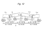
  • the force F ri generated by a relative rotation between the vehicle body 2 i and the vehicle body 2 i+1 is expressed as illustrated in Fig. 12 .
  • a force working in a direction for reducing the relative rotation between the number i vehicle body 2 i and the number i+1 vehicle body 2 i+1 by a spring component k r and a damping component C r is expressed as a sum of a force f ri-1 (i) applied to the front end of the number i vehicle body (the coupling portion 3 i-1 of the bogie 4 i-1 corresponding to the bogie number i-1) perpendicularly to the vehicle body 2 i , and a force f ri+1 (i+1) applied to the rear end of the number i+1 vehicle body (the coupling portion 3 i+1 of the bogie 4 i+1 corresponding to the bogie number i+1) perpendicularly to the vehicle body
  • f ra (b) represents a component force of the force applied to the coupling portion 3 a corresponding to the bogie number a that is applied to the b-th vehicle body 2 b .
  • the forces f ri-1 (i) and f ri+1 (i+1) are expressed by the following equation.
  • the pitching angle ⁇ i is sufficiently small at the vehicle body 2 i of the railway train 1 so that this is approximated in the following manner.
  • a state vector x, a disturbance input w, and a control input u (the number i bogie control force instruction u i ) have the following contents, respectively.
  • x z ⁇ B ⁇ 1 z ⁇ B ⁇ 2 ⁇ z ⁇ Bn z B ⁇ 1 z B ⁇ 2 ⁇ z Bn ⁇ ⁇ 1 ⁇ ⁇ 2 ⁇ ⁇ ⁇ n ⁇ ⁇ 1 ⁇ ⁇ 2 ⁇ n T
  • DISTURBANCE INPUT > w z T ⁇ 0 ⁇ z T ⁇ 1 ⁇ z Tn T
  • CONTROL INPUT > u 0 ⁇ u 1 ⁇ u n T
  • the control law is developed with use of this state equation based on LG control by way of example.
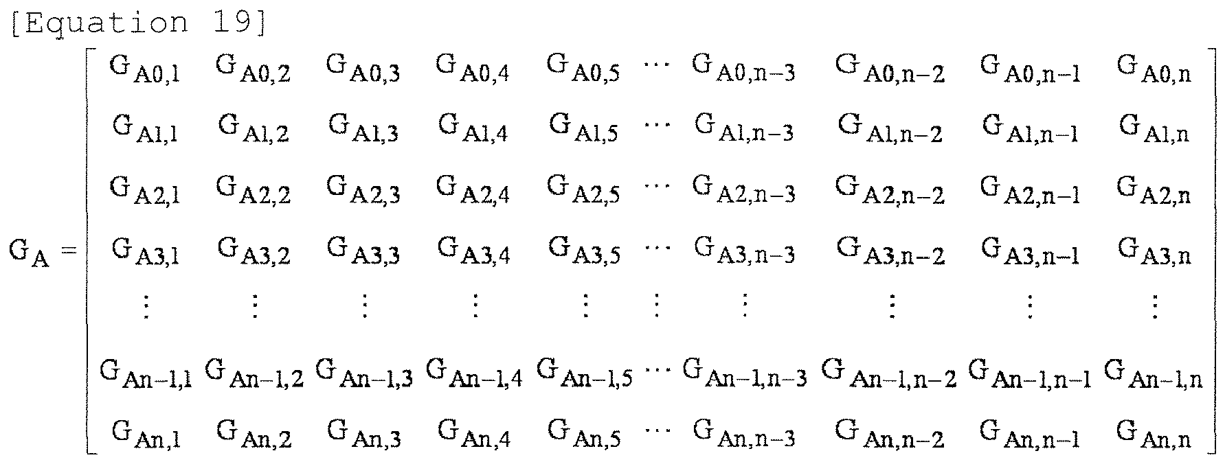
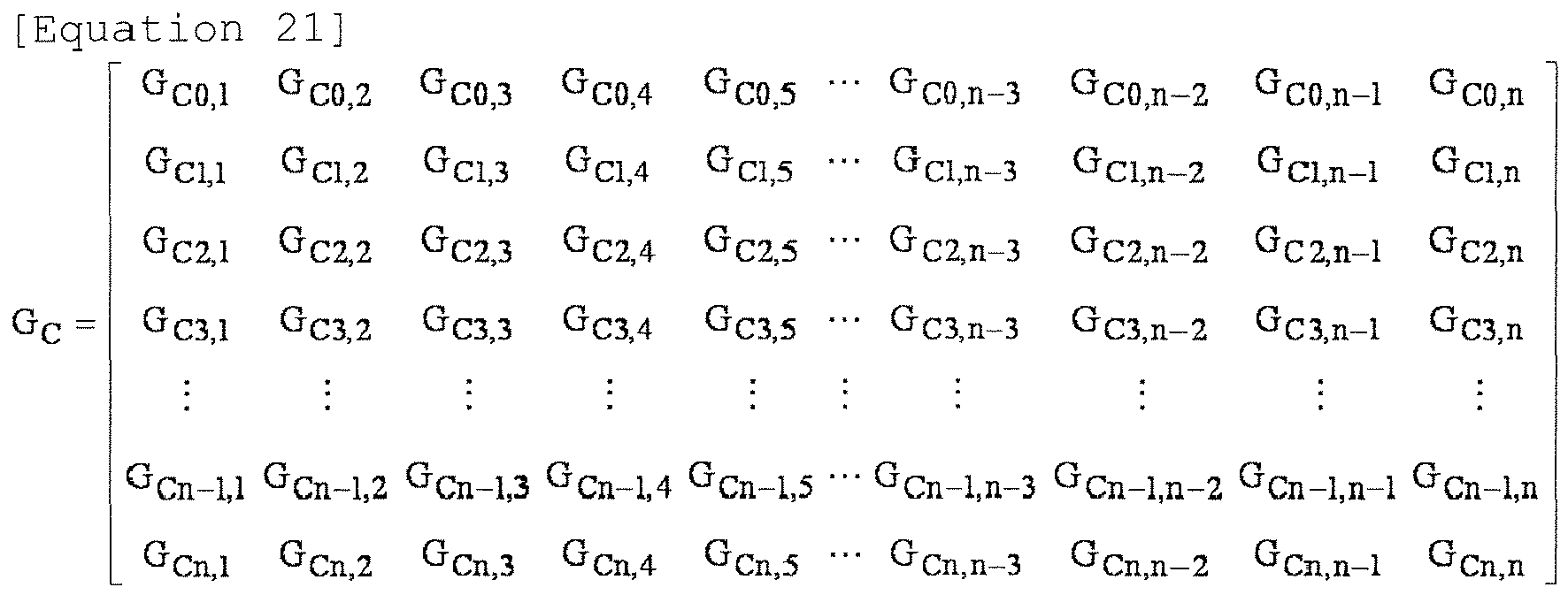
  • the state feedback K acquired at this time is expressed by the following matrix constituted by n rows and 4 ⁇ n columns.
  • G A represents a control gain matrix for the vertical speed (dz Bi /dt)
  • G B represents a control gain matrix for the vertical displacement z Bi .
  • G c represents a control gain matrix for the pitching angular speed (d ⁇ i /dt)
  • G D represents a control gain matrix for the pitching angle ⁇ 1 .
  • G A G A ⁇ G B ⁇ G C ⁇ G D
  • G A G A ⁇ 0 , 1 G A ⁇ 0 , 2 G A ⁇ 0 , 3 G A ⁇ 0 , 4 G A ⁇ 0 , 5 ⁇ G A ⁇ 0 , n - 3 G A ⁇ 0 , n - 2 G A ⁇ 0 , n - 1 G A ⁇ 0 , n G A ⁇ 1 , 1 G A ⁇ 1 , 2 G A ⁇ 1 , 3 G A ⁇ 1 , 4 G A ⁇ 1 , 5 ⁇ G A ⁇ 1 , n - 3 G A ⁇ 1 , n - 2 G A ⁇ 1 , n - 1 G A ⁇ 1 , n G A ⁇ 2 , 1 G A ⁇ 2 , 2 G A ⁇ 2 , 3 G A ⁇ 2 , 4 G A ⁇ 2 , 5 ⁇ G A ⁇ 2 , 5
  • a multi-degree-of-freedom vibration of the entire railway train is set as a control target, and the control force for each vertically movable damper 7 is determined in consideration of an interference between the vehicle bodies 2 i and 2 i+1 , whereby it is possible to improve the ride comfort of the entire railway train 1.
  • the state feedback K does not necessarily have to be acquired from the above-described LQ control, and may be acquired from any of various kinds of control theories such as LQG control and H ⁇ .
  • the above-described system is realized while the acceleration components (d2z Bi /dt2 and d2 ⁇ i /dts) of the state vector x are acquired with use of the acceleration a i directly above the number i bogie 4 i detected by the acceleration sensor 9 i .
  • the present invention is not limited thereto, and the state amount may be acquired from a detection result (information) of the acceleration sensor 9 i or may be estimated by designing an appropriate state observer.
  • the ride comfort of the railway train 1 is affected by an acceleration of a lateral vibration of the vehicle body 2 i such as yawing and swaying, an acceleration of a vertical vibration of the vehicle body 2 i such as rolling, pitching, and bouncing, and a relatively low-frequency acceleration such as a lateral stable acceleration generated when the railway train is running on a curved track and a longitudinal acceleration generated when the railway train is accelerating or decelerating.
  • a relatively low-frequency acceleration such as a lateral stable acceleration generated when the railway train is running on a curved track and a longitudinal acceleration generated when the railway train is accelerating or decelerating.
  • the ride comfort against a lateral movement is especially important for vehicles entering a narrow tunnel at a high speed or vehicles running in a section frequently having alignment irregularity of a track.
  • active suspensions working laterally have been in widespread use for such vehicles, and in recent years, the ride comfort has been improved.
  • the ride comfort in the lateral direction is also affected by a combination of rolling, lateral translation, and yawing, but the ride comfort has been also improved against them by using both the lateral active suspension and a vehicle body tilting apparatus (including a pendulum device).
  • the improvement of the ride comfort in the lateral direction in this manner resultingly makes the discomfort in the vertical direction in riding, which relates to track irregularity in the vertical direction, relatively conspicuous.
  • the discomfort in riding in the vertical direction has been conspicuous for vehicles running in a section having a wide tunnel, a section having less tunnels, a section having many straight tracks, a section having less tracks with alignment irregularity, or a section having a track with a large degree of longitudinal level irregularity.
  • the vehicle bodies 2 i and 2 i+1 are vertically inflexibly coupled to each other by the coupling portion 3 i so that the vertical vibration of the vehicle body 2 i is strongly affected by the vertical vibrations of the adjacent vehicle bodies 2 i-1 and 2 i+1 . Therefore, all of the vehicle bodies 2 1 to 2 n coupled by the coupling bogies 4 1 to 4 n-1 are influentially linked to one another.
  • the vertically movable dampers 7 are in charge of absorbing vibrations of these vehicle bodies 2 1 to 2 n , whereby only controlling the vertically movable dampers 7 to generate the damping forces for damping the vibration of their own vehicle body 2 i cannot be sufficiently effective to reduce the vibration of the vehicle body 2 i .
  • the controller 10 calculates the number i bogie control force instruction u i , which is the instruction values for the actuators 7A of the bogie 4 i , based on the detection values of the vibrations at all of the vehicle bodies 2 1 to 2 n . Therefore, even if all of the vehicle bodies 2 1 to 2 n coupled by the coupling bogies 4 1 to 4 n-1 are influentially linked to one another, it is possible to control the vertically movable dampers 7 of the bogie 4 i in consideration of the influence of the vibrations of the vehicle bodies 2 1 to 2 n among one another. As a result, it is possible to reduce the vibration of the vehicle body 2 i in the entire railway train 1, which is the coupling bogie train having the n vehicle bodies 2 1 to 2 n , thereby improving the ride comfort.
  • the railway train 1 detects the acceleration a i-1 of the vehicle body 2 i-1 with use of the acceleration sensor 9 i-1 mounted at the coupling portion 3 i-1 , detects the acceleration a i+1 of the vehicle body 2 i+1 with use of the acceleration sensor 9 i+1 mounted at the coupling portion 3 i+1 . and detects the acceleration a i of the coupling portion 3 i with use of the acceleration sensor 9 i mounted at the coupling portion 3 i .
  • the railway train 1 can calculate the vibration of the vehicle body 2 i based on the detection value of the acceleration a i-1 by the acceleration sensor 9 i-1 and the detection value of the acceleration a i by the acceleration sensor 9 i , and calculate the vibration of the vehicle body 2 i+1 based on the detection value of the acceleration a i+1 by the acceleration sensor 9 i+1 and the detection value of the acceleration a i by the acceleration sensor 9 i .
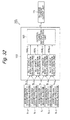
  • all of the acceleration sensors 9 0 to 9 n , and the vertically movable dampers 7 of all of the bogies 4 0 to 4 n are connected to the single controller 10.
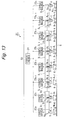
  • the present invention is not limited thereto, and may share the acceleration information and the control instructions for the vertically movable dampers 7 among the vehicle bodies via a digital signal such as communication, like, for example, a railway train 21 according to a first modification illustrated in Fig. 13 .
  • a controller 22 includes n+1 child devices 23 0 to 23 n and a single parent device 24.
  • the child devices 23 0 to 23 n are located, for example, very close to the respective vertically movable dampers 7, and respectively acquire the detection signals of the acceleration sensors 9 0 to 9 n to output this information to a communication line 25. Further, the child devices 23 0 to 23 n output instruction currents to the actuators 7A of the vertically movable dampers 7 as damping force instructions according to control force information (the number i bogie control force instruction u i ) in the communication line 25.
  • the parent device 24 acquires the acceleration information of the n vehicle bodies from the communication line 25, and calculates control forces (the number i bogie control force instruction u i ) required for the respective vertically movable dampers 7 according to the above-described control law.
  • the parent device 24 transmits a result of this calculation to the child devices bogies 23 0 to 23 n via the communication line 25.
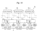
  • Figs. 14 and 15 illustrate a second embodiment of the present invention.
  • the second embodiment is characterized in that the controller calculates the control force of the coupling bogie based on vibrations of two vehicle bodies. Similar elements of the second embodiment to the above-described first embodiment will be identified by the same reference numerals as the first embodiment, and will not be described especially.
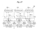
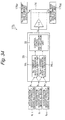
  • a railway train 31 according to the second embodiment includes the vehicle body 2 i , the coupling portion 3 i , the bogie 4 i , the vertically movable dampers 7, the acceleration sensor 9 i , a controller 32 i , and the like, in a substantially similar manner to the railway train 1 according to the first embodiment.
  • the controller 32 i is configured in a similar manner to the controller 10 according to the first embodiment with use of, for example, a microcomputer.
  • the railway train 31 includes total n+1 controllers 32 0 to 32 n corresponding to the number of bogies 4 0 to 4 n .
  • These controllers 32 0 to 32 n control the vertically movable dampers 7 of the bogies 4 0 to 4 n respectively independently.
  • the term "controller 32 i " will be used to refer to any of the controllers 32 0 to 32 n .
  • the actuators 7A of the vertically movable dampers 7 of the bogie 4 i are connected to an output side of the controller 32 i .
  • the acceleration sensors 9 i-1 , 9 i , and 9 i+1 are connected to an input side of the controller 32 i .
  • the controller 32 i generates the number i bogie control force instruction u i , which is the damping force instruction signals for the vertically movable dampers 7 of the bogie 4 i , based on the detection signals from the three acceleration sensors 9 i-1 , 9 i , and 9 i+1 , and variably controls the damping forces of these vertically movable dampers 7.
  • the controller 32 i includes a preprocessing unit (not illustrated) that includes the AD converter, the filter processing unit, and the like, and acquires the accelerations a i-1 , a i , and a i+1 from the detection signals of the acceleration sensors 9 i-1 , 9 i , and 9 i+1 .
  • the controller 32 further includes a vibration control unit 33 that outputs the number i bogie control force instruction u i according to the instruction values for the actuators 7A based on the accelerations a i-1 , a i , and a i+1 .
  • the vibration control unit 33 includes a number i vehicle body vibration calculation unit 34 i that calculates the vibration of the vehicle body 2 i based on the accelerations a i-1 and a i as the detection values of the acceleration sensors 9 i-1 and 9 i , a number i+1 vehicle body vibration calculation unit 34 i+1 that calculates the vibration of the vehicle body 2 i+1 based on the accelerations a i and a i+1 as the detection values of the acceleration sensors 9 i and 9 i+1 , and a control force instruction calculation unit 35 that calculates the number i bogie control force instruction u i for the vertically movable dampers 7 of the bogie 4 i based on the vibrations of the vehicle bodies 2 i and 2 i+1 calculated by these vehicle body vibration calculation units 34 i and 34 i+1 .
  • the vehicle body vibration calculation units 34 i and 34 i+1 are configured in a substantially similar manner to the number i vehicle body vibration calculation unit 12 i according to the first embodiment. Therefore, the vehicle body vibration calculation units 34 i and 34 i+1 calculate the vibrations of the vehicle bodies 2 i and 2 i+1 based on the equations 1 and 2. Further, the control force instruction calculation unit 35 calculates the number i bogie control force instruction u i according to a control law, which will be described below.
  • the number i bogie control force instruction u i calculated by the control force instruction calculation unit 35 is input into the number i bogie current output unit 14 i , and the number i bogie current output unit 14 i supplies instruction currents according to the number i bogie control force instruction U i to the actuators 7A of the vertically movable dampers 7 of the bogie 4 i .
  • the vibration of the vehicle body 2 i due to pitching and bouncing is damped so that the ride comfort of the vehicle body 2 i can be improved.
  • the railway train 31 configured in the above-described manner controls the damping forces of the vertically movable dampers 7 of each bogie 4 i based on the outputs of the acceleration sensors 9 i-1 , 9 i , and 9 i+1 according to a control law that will be described next.
  • the control law according to the second embodiment is basically similar to the first embodiment. However, a difference from the first embodiment is that the state feedback K is approximated in the following manner.
  • the control according to the second embodiment will be described especially focusing on the state feedback K acquired from the various kinds of control theories indicated by the equations 18 to 22 according to the first embodiment.
  • the state feedback K acquired from the control law such as optimum feedback
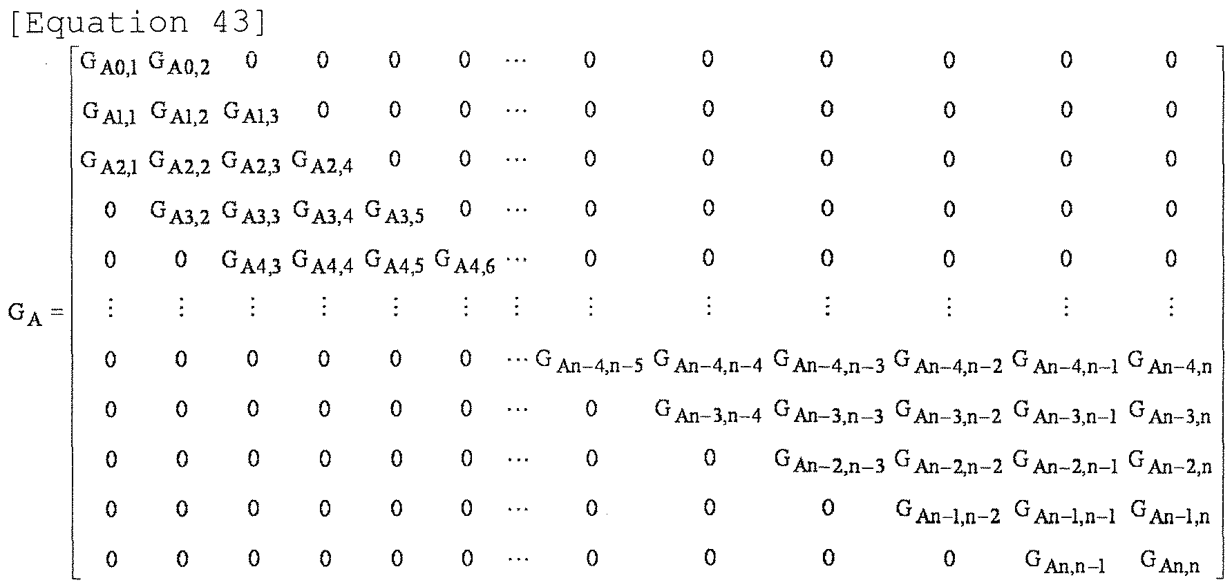
  • a gain is large mainly around diagonal elements in the matrix, and a gain of a non-diagonal element is getting smaller as it is located farther away from the diagonal elements. Focusing on this tendency, gains away from the diagonal elements among the non-diagonal elements are approximated to zero, and the state feedback K is approximated, for example, in the following manner.
  • G A G A ⁇ 0 , 1 0 0 0 0 ⁇ 0 0 0 G A ⁇ 1 , 1 G A ⁇ 1 , 2 0 0 0 ⁇ 0 0 0 0 G A ⁇ 2 , 2 G A ⁇ 2 , 3 0 0 ⁇ 0 0 0 0 G A ⁇ 3 , 3 G A ⁇ 3 , 4 0 ⁇ 0 0 0 0 0 0 0 0 ⁇ ⁇ ⁇ ⁇ ⁇ ⁇ 0 0 0 0 0 0 ⁇ G An - 3 , n - 3 G An - 3 , n - 2 0 0 0 0 0 0 ⁇ 0 G An - 3 , n - 3 G An - 3 , n - 2 0 0 0 0 0 ⁇ 0 G An - 2 , n - 1 0 0 0 0 0 ⁇
  • control force to be generated at the vertically movable dampers 7 of the number i bogie 4 i is expressed by the following recurrence relation.
  • u i G Ai , i ⁇ z ⁇ Bi + G Ai , i + 1 ⁇ z ⁇ Bi + 1 + G Bi , i ⁇ z Bi + G Bi , i + 1 ⁇ z Bi + 1 + G Ci , i ⁇ ⁇ ⁇ i + G Ci , i + 1 ⁇ ⁇ ⁇ i + 1 + G Di , i ⁇ ⁇ i + G Di , i + 1 ⁇ ⁇ i + 1
  • the control force to be generated at the vertically movable dampers 7 of the number i bogie 4 i is determined only by motions of the number i vehicle body (the vehicle body 2 i ) and the number i+1 vehicle body (the vehicle body 2 i+1 ).
  • the controller 32 i is disposed very close to the dampers 7, and the controller 32 i determines the control force only from the acceleration information of its own vehicle body (the vehicle body 2 i ) and the adjacent vehicle body (the vehicle body 2 i+1 ) according to the above-described recurrence relation.
  • the length of the signal line laid between the acceleration sensor 9 i and the vertically movable dampers 7, and the controller 32 i can be reduced to, for example, approximately a length only for two vehicle bodies. Further, the calculation amount of the controller 32 i can be also reduced. Therefore, the present embodiment can acquire a similar performance to the first embodiment with a simple configuration.
  • a simulation result of PSD of bouncing of the vehicle body 2 i is illustrated in Fig. 16
  • a simulation result of PSD of pitching of the vehicle body 2 i is illustrated in Fig. 17 , as a vibration control effect by the above-described control law.
  • a solid line indicates PSD when the second embodiment is employed.
  • a broken line indicates PSD when a passive hydraulic damper that does not perform active control is employed as a first comparative example.
  • a long dashed short dashed line indicates PSD when the vertical acceleration of the vehicle body 2 i directly above the coupling portion 3 i is acquired, and the vertically movable dampers 7 directly below the coupling portion 3 i are controlled so as to reduce a change in this acceleration, as a second comparative example.
  • the second embodiment can reduce both bouncing and pitching compared to use of the passive damper and control of the vertically movable dampers 7 based on only the vibration directly above the coupling portion 3 i .
  • the second embodiment can also acquire a similar result and effect to the first embodiment.
  • cables of the n+1 acceleration sensors 9 0 to 9 n mounted at the n vehicle bodies 2 1 to 2 n , and control lines of the (n+1) ⁇ 2 vertically movable dampers 7 are laid toward the single controller 10.
  • problems such as complication of the wiring layout, an easy entry of a noise into the cables, and a failure in keeping the accuracy of an analog signal.
  • the acceleration information and the control instructions for the vertically movable dampers 7 are shared among the vehicle bodies via a digital signal such as communication.
  • a delay is generated in each of acquisition of the accelerations and transmission of the acceleration information through communication by the child devices 23 0 to 23 n , reception of the acceleration information and transmission of the control calculations and the control force instructions by the parent device 24, and reception of the control force instructions and outputs of currents to the vertically movable dampers 7 by the child devices 23 0 to 23 n .
  • the communication cable (the communication line 25) is required to transmit data in a noise-prone environment over more than 100 m, thereby being difficult to be configured to handle high-speed communication.
  • the controller 32 i calculates the number i bogie control force instruction u i , which is the instruction values for the actuators 7A of the vertically movable dampers 7 of the bogie 4 i , based on the vibrations of the vehicle body 2 i and the vehicle body 2 i+1 disposed on the opposite front side and rear side of the bogie 4 i . Therefore, only a length for two vehicle bodies is enough as the length of the cable connecting the acceleration sensors 9 i-1 , 9 i , and 9 i+1 and the vertically movable dampers 7 to the controller 32 i , whereby the wiring layout can be simplified and the noise can be reduced. In addition thereto, the ride comfort control calculation can be simplified, whereby the manufacturing cost can be reduced.
  • Fig. 18 illustrates a third embodiment of the present invention.
  • the third embodiment is characterized in that the controller calculates the instruction values for the actuators after removing a component of a gradual acceleration change like a change in a slope of a road surface. Similar elements of the third embodiment to the above-described second embodiment will be identified by the same reference numerals as the second embodiment, and will not be described especially.
  • a controller 41 i according to the third embodiment is configured in a substantially similar manner to the controller 32 i according to the second embodiment. Therefore, the controller 41 i includes the vibration control unit 33 including the number i vehicle body vibration calculation unit 34 i , the number i+1 vehicle body vibration calculation unit 34 i+1 , and the control instruction calculation unit 35. Further, the controller 41 i includes a preprocessing unit 42 that acquires the acceleration a i from the detection signal of the acceleration sensor 9 i .
  • This preprocessing unit 42 includes an acceleration acquisition unit 42A, a low-pass filter 42B (hereinafter referred to as the LPF 42B), a high-pass filter 42C (hereinafter referred to as the HPF 42C), and a phase compensator 42D.
  • the acceleration acquisition unit 42A includes the AD converter and the like, and acquires the acceleration a i by converting the detection signal of the acceleration sensor 9 i into a digital signal.
  • the LPF 42B removes a highfrequency noise superimposed on the input of the acceleration a i with its cutoff frequency set to, for example, a value equal to or lower than a half of a sampling frequency.
  • the HPF 42C keeps a frequency component of bouncing and pitching while removing a component of a gradual acceleration change according to a change in a situation of a road surface with its cutoff frequency set to a lower value than a low-frequency side of a resonance frequency of bouncing and pitching of the vehicle body 2 i .
  • a resonance point of bouncing and pitching of the vehicle body 2 i is generated, for example, at a frequency of about 1 to 2 Hz.
  • an offset component due to an ascending slope or a descending slope is generated at, for example, a frequency of 0.5 Hz or lower. Therefore, the cutoff frequency of the HPF 42C is set to, for example, about 0.5 Hz as a value between the resonance frequency of bouncing and pitching, and the frequency of the offset component.
  • the cutoff frequency of the HPF 42C is not limited to the above-described one, and is determined from an experiment in consideration of, for example, a vibration when the railway train runs actually.
  • the phase compensator 42D improves a phase characteristic when a desired phase characteristic cannot be acquired around a control frequency by the LPF 42B and HPF 42C.
  • the LPF 42B, the HPF 42C, and the phase compensator 42D each include a digital filter or the like based on digital signal processing.
  • the vibration control unit 33 calculates the number i bogie control force instruction u i based on the detection value of the acceleration a i output from this preprocessing unit 42, and output the calculated instruction to the number i bogie current output unit 14 i .
  • the third embodiment can also acquire a similar result and effect to the second embodiment.
  • the controller 32 i generates the control force instruction so as to reduce a change in the pitching angular speed and a change in the vertical speed of the vehicle body 2 i . Therefore, the control according to the second embodiment leads to generation of a control force instruction to prevent the vehicle body 2 i from moving (a change in the pitching angular speed and a change in the vertical speed) when the railway train 31 is entering an ascending slope track, when the railway train 31 is exiting the ascending slope track, when the railway train 31 is entering a descending slope track, when the railway train 31 is exiting the descending slope track, or when partial vehicles in the railway train 31 are running on an ascending slope track while other vehicles in the railway train 31 are running on a descending slope track.
  • This control force instruction is an instruction for extending up the vehicle body 2 i , compressing down the vehicle body 2 i , or inclining the vehicle body 2 i forward or downward, and combining this instruction to the ride comfort control instruction results in deterioration of the ride comfort when the railway train 31 is entering a slope track. Further, an offset is generated in the vertical acceleration a i of the vehicle body 2 i when the railway train 31 is accelerating or decelerating on an ascending or descending slope track or when the railway train 31 is running along a curved track with the vehicle body 2 i inclined, and this offset affects the ride comfort.
  • the controller removes the component of a gradual acceleration change, like a change in a slope of a road surface, with use of the HPF 42C, and therefore can provide control only to the acceleration a i due to pitching and bouncing to improve the ride comfort on an ascending slope track and a descending slope track.
  • the third embodiment has been described based on the example in which this is applied to the second embodiment, but may be applied to the first embodiment.
  • Fig. 19 illustrates a fourth embodiment of the present invention.
  • the fourth embodiment is characterized in that the controller switches control gains according to weights of adjacent two vehicle bodies. Similar elements of the fourth embodiment to the above-described second embodiment will be identified by the same reference numerals as the second embodiment, and will not be described especially.
  • a controller 51 i according to the fourth embodiment is configured in a substantially similar manner to the controller 32 i according to the second embodiment.
  • the controller 51 i includes a preprocessing unit 52 that acquires the acceleration a i from the detection signal of the acceleration sensor 9 i .
  • This preprocessing unit 52 includes an acceleration acquisition unit 52A, a low-pass filter 52B (hereinafter referred to as the LPF 52B), a high-pass filter 52C (hereinafter referred to as the HPF 52C), and a phase compensator 52D.
  • the acceleration acquisition unit 52A includes the AD converter and the like, and acquires the acceleration a i by converting the detection signal of the acceleration sensor 9 i into a digital signal.
  • the LPF 52B removes a noise or the like on a higher frequency side than the frequency of bouncing and pitching of the vehicle body 2 i .
  • the HPF 52C removes an unnecessary signal such as a noise on a lower frequency side than the frequency of bouncing and pitching of the vehicle body 2 i .
  • the phase compensator 52D improves the phase characteristic when a desired phase characteristic cannot be acquired around the control frequency by the LPF 52B and the HPF 52C.
  • the controller 51 i includes a tank water level acquisition unit 53, a number i vehicle body weight balance calculation unit 54 i , and a number i+1 vehicle body weight balance calculation unit 54 i+1 .
  • the tank water level acquisition unit 53 includes an AD converter and the like, and is connected to a number i vehicle body clean water tank water meter 55 i , a number i vehicle body sewage water tank water meter 56 i , a number i+1 vehicle body clean water tank water meter 55 i+1 , and a number i+1 vehicle body sewage water tank water meter 56 i+1 .
  • the tank water level acquisition unit 53 acquires a water amount Q ai in a clean water tank and a water amount Q bi in a sewage water tank of the number i vehicle body, and acquires a water amount Q ai+1 in a clean water tank and a water amount Q bi+1 in a sewage water tank of the number i+1 vehicle body.
  • the number i vehicle body weight balance calculation unit 54 i calculates number i vehicle body weight balance based on the water amounts Q ai and Q bi in the tanks of the number i vehicle body, and outputs a signal according to a balance inertia and a weight of the vehicle body 2 i .
  • the number i+1 vehicle body weight balance calculation unit 54 i+1 calculates number i+1 vehicle body weight balance based on the water amounts Q ai+1 and Q bi+1 in the tanks of the number i+1 vehicle body, and outputs a signal according to a balance inertia and a weight of the vehicle body 2 i+1 .
  • the controller 51 i includes a vibration control unit 57 similar to the vibration control unit 33 according to the second embodiment. Therefore, the vibration control unit 57 includes a number i vehicle body vibration calculation unit 58 i , a number i+1 vehicle body vibration calculation unit 58 i+1 , and a control force instruction calculation unit 59 substantially similar to the number i vehicle body vibration calculation unit 34 i , the number i+1 vehicle body vibration calculation unit 34 i+1 , and the control force instruction calculation unit 35 according to the second embodiment.
  • the vibration control unit 57 includes a memory 60 that stores a plurality of kinds (for example, M kinds) of control gains G Ai,i (1) to G Ai,i (M), G Ai,i+1 (1) to G Ai,i+1 (M), G Ci,i (1) to G Ci,i (M), and G Ci,i+1 (1) to G Ci,i+1 (M), and a parameter selection unit 61 that selects one kind of gains from the control gains G Ai,i (1) to G Ai,i (M), G Ai,i+1 (1) to G Ai , i+1 (M), G Ci,i (1) to G Ci,i (M), and G Ci,i+1 (1) to G Ci,i+1 (M) stored in the memory 60 based on the signals output from the weight balance calculation units 54 i and 54 i+1 .
  • M kinds for example, M kinds
  • the parameter selection unit 61 supplies the selected one kind of gains G Ai,i (m), G Ai,i+1 (m), G Ci,i (m), and G Ci,i+1 (m) to the control force instruction calculation unit 59 as control gains G Ai,i , G Ai,i+1 , G Ci,i , and G Ci,i+1 .
  • the parameter selection unit 61 increases the control gain G Ai,i of the heavier vehicle body and reduces the control gain G Ai,i+1 of the lighter vehicle. Further, when the number i vehicle body has a larger inertia in the pitching direction than the number i+1 vehicle body, the parameter selection unit 61 increases the control gain G Ci,i(1) for the pitching angle ⁇ i of the vehicle body 2 i having the larger inertia, and reduces the control gain G Ci,i+1 for the pitching angle ⁇ i+1 of the vehicle body 2 i+1 having a smaller inertia.
  • the relationship of the weight and inertia to the control gains G Ai,i , G Ai,i+1 , G Ci,i , and G Ci,i+1 is not limited thereto, and an optimum relationship capable of reducing the vibration of the vehicle body 2 i is determined based on the vibration of the vehicle body 2 i when the railway train runs actually. Further, the number of kinds as the control gains G Ai,i and G Ai , i+1 for the vertical speed (dz Bi /dt) and the number of kinds as the control gains G Ci,i and G Ci,i+1 for the pitching angular speed (d ⁇ i /dt) do not necessarily have to be same numbers , and may be different from each other.
  • control force instruction calculation unit 59 calculates the number i bogie control force instruction u i with use of the control gains selected by the parameter selection unit 61, and outputs it to the number i bogie current output unit 14 i .
  • the fourth embodiment can also acquire a similar result and effect to the second embodiment.
  • control gains G Ai,j , G Bi,j , G Ci,j , and G Di,j are fixed values tuned in advance, provided that the weight of the vehicle body 2 i and the coupling stiffness between the vehicle bodies 2 i and 2 i+1 are not changed while the railway train is running.
  • the weight balance may be disturbed due to consumption of a loaded fuel by a diesel railcar, a change in the balance between clean water and sewage water in a sleeper train, a difference in vehicle occupancy among the vehicle bodies, and the like.
  • the fourth embodiment prepares a plurality of kinds of control gains G Ai,j (1) to G Ai,j (M) and G Ci,j (1) to G Ci,j (M) in consideration of a change in the weight balance of the vehicle body. Then, for example, the fourth embodiment switches the ratio between the control gain G Ai,i and the control gain G Ai , i+1 depending on a difference between the weights of the number i vehicle body and the number i+1 vehicle body, and switches the ratio between the control gain G Ci,i and the control gain G Ci,i+1 depending on a difference in the inertias of the number i vehicle body and the number i+1 vehicle body.
  • the fourth embodiment increases one of the control gains G Ai,i and G Ai , i+1 for bouncing of the vehicle body that corresponds to a heavier vehicle body. Further, when the number i vehicle body and the number i+1 vehicle body have different inertias in the pitching direction, the fourth embodiment increases one of the control gains G Ci,i and G Ci,i+1 for the pitching angle ⁇ i of the vehicle body that corresponds to the pitching angle ⁇ i of the vehicle body 2 i or 2 i+1 having a larger inertia. As a result, even when the weight or inertia of the vehicle body 2i is changed, the fourth embodiment can reduce the vibration of the vehicle body 2 i by selecting the control gain G Ai,j and G Ci,j according to this change.
  • the balance between the control gains for bouncing and pitching i.e., the balance among the control gains G Ai,j to G Di,j may be changed arbitrarily.
  • the fourth embodiment acquires the water amounts Q ai and Q ai+1 in the clean water tanks and the water amounts Q bi and Q b+1 in the sewage water tanks respectively measured by the clean water tank water-meters 55 i and 55 i+1 and the sewage water tank water-meters 56 i and 56 i+1 , and detects changes in the weight and inertia as a change in the weight balance of the vehicle body 2 i based on the balance between these clean water and sewage water.
  • the present invention is not limited thereto.
  • a weight change due to fuel consumption may be detected based on a driving time or a fuel meter, and a difference in vehicle occupancy may be detected based on an initial displacement of the secondary suspension or the like. Further, the weight and inertia of the vehicle body 2 i may be measured directly.
  • the fourth embodiment is configured to include the vibration control unit 57 similar to the vibration control unit 33 according to the second embodiment, but may be configured to include the vibration control unit 11 according to the first embodiment. Further, the fourth embodiment may be combined with the third embodiment.
  • Fig. 20 illustrates a fifth embodiment of the present invention.
  • the fifth embodiment is characterized in that the controller switches the control gains according to a vehicle speed. Similar elements of the fifth embodiment to the above-described fourth embodiment will be identified by the same reference numerals as the fourth embodiment, and will not be described especially.
  • a controller 71 i according to the fifth embodiment includes the preprocessing unit 52 according to the fourth embodiment.
  • the controller 71 i includes a speed information acquisition unit 72.
  • the speed information acquisition unit 72 is connected to, for example, a communication line 73 within the vehicle body, and acquires a vehicle speed from the communication line 73.
  • the speed information acquisition unit 72 does not necessarily have to acquire the vehicle speed based on a signal from the communication line 73, and may acquire the vehicle speed based on a signal from, for example, a speed sensor.
  • the controller 71 i includes a vibration control unit 74 similar to the vibration control unit 33 according to the second embodiment. Therefore, the vibration control unit 74 includes a number i vehicle body vibration calculation unit 75 i , a number i+1 vehicle body vibration calculation unit 75 i+1 , and a control force instruction calculation unit 76 substantially similar to the number i vehicle body vibration calculation unit 34 i , the number i+1 vehicle body vibration calculation unit 34 i+1 , and the control force instruction calculation unit 35 according to the second embodiment. In addition thereto, the vibration control unit 74 includes a memory 77 and a parameter selection unit 78 substantially similar to the memory 60 and the parameter selection unit 61 according to the fourth embodiment.
  • the memory 77 stores the plurality of kinds (for example, M kinds) of control gains G Ai,i (1) to G Ai,i (M), G Ai,i+1 (1) to G Ai,i+1 (M), G Ci,i (1) to G Ci,i (M), and G Ci,i+1 (1) to G Ci,i+1 (M).
  • the parameter selection unit 78 selects one kind of control gains from G Ai,i (1) to G Ai,i (M), G Ai,i+1 (1) to G Ai,i+1 (M), G Ci,i (1) to G Ci,i (M), and G Ci,i+1 (1) to G Ci,i+1 (M) stored in the memory 77 based on a signal output from the speed information acquisition unit 72.
  • the parameter selection unit 78 supplies the selected one kind of gains G Ai,i (m), G Ai,i+1 (m), G Ci,i (m), and G Ci,i+1 (m) to the control force instruction calculation unit 76 as the control gains G Ai,i , G Ai,i+1 , G Ci,i , and G Ci,i+1 .
  • the parameter selection unit 78 increases the control gains G Ai,i , G Ai,i+1 , G Ci,i , and G Ci,i+1 when the vehicle speed is fast, and reduces the control gains G Ai,i , G Ai,i+1 , G Ci,i , and G Ci,i+1 when the vehicle speed is slow.
  • the number of kinds as the control gains G Ai,i and G Ai , i+1 for the vertical speed (dz Bi /dt) and the number of kinds as the control gains G Ci,i and G Ci,i+1 for the pitching angular speed (d ⁇ i /dt) do not necessarily have to be same numbers , and may be different from each other.
  • control force instruction calculation unit 76 calculates the number i bogie control force instruction u i with use of the control gains selected by the parameter selection unit 78, and outputs the calculated instruction to the number i bogie current output unit 14 i .
  • the fifth embodiment can also acquire a similar result and effect to the second embodiment. Further, if there is no large peak in a spatial frequency of vertical irregularity of the track, the ride comfort is further deteriorated as the running speed of the vehicle is increasing. Even in this case, the fifth embodiment can prevent the ride comfort from being deteriorated due to a change in the vehicle speed because it changes the control gains G Ai,i and G Ci,i according to the vehicle speed.
  • the fifth embodiment is configured to include the vibration control unit 74 similar to the vibration control unit 33 according to the second embodiment, but may be configured to include the vibration control unit 11 according to the first embodiment. Further, the fifth embodiment may be combined with the third or fourth embodiment.
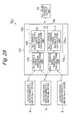
  • Fig. 21 illustrates a sixth embodiment of the present invention.
  • the sixth embodiment is characterized in that the controller switches the control gains when the railway train is running on an ascending slope track or is accelerating. Similar elements of the sixth embodiment to the above-described fourth embodiment will be identified by the same reference numerals as the fourth embodiment, and will not be described especially.
  • a controller 81 i according to the sixth embodiment includes the preprocessing unit 52 according to the fourth embodiment.
  • the controller 81 i includes a traveling direction acquisition unit 82, an inclination angle acquisition unit 83, and a longitudinal acceleration acquisition unit 84.
  • the traveling direction acquisition unit 82 is connected to, for example, a communication line 85 within the vehicle body, and acquires a traveling direction of the vehicle body from the communication line 85.
  • the inclination angle acquisition unit 83 is connected to, for example, an angle meter 86 that detects an inclination of the vehicle body, and acquires how much the vehicle body is inclined.
  • the longitudinal acceleration acquisition unit 84 is connected to, for example, a longitudinal acceleration sensor 87, and acquires a longitudinal acceleration.
  • the traveling direction acquisition unit 82 may acquire the traveling direction from a speed sensor of the vehicle body.
  • the inclination angle acquisition unit 83 may acquire how much the vehicle body is inclined based on location information of the vehicle body from a GPS, a traffic control sensor, or the like.
  • the longitudinal acceleration acquisition unit 84 may acquire the longitudinal acceleration by differentiating speed information of the vehicle.
  • the controller 81 i includes a vibration control unit 88 similar to the vibration control unit 33 according to the second embodiment. Therefore, the vibration control unit 88 includes a number i vehicle body vibration calculation unit 89 i , a number i+1 vehicle body vibration calculation unit 89 i+i , and a control force instruction calculation unit 90 substantially similar to the number i vehicle body vibration calculation unit 34 i , the number i+1 vehicle body vibration calculation unit 34 i+1 , and the control force instruction calculation unit 35 according to the second embodiment. In addition thereto, the vibration control unit 88 includes a memory 91 and a parameter selection unit 92 substantially similar to the memory 60 and the parameter selection unit 61 according to the fourth embodiment.
  • the memory 91 stores the plurality of kinds (for example, M kinds) of control gains G Ai,i (1) to G Ai,i (M), G A1,i+1 (1) to G Ai,i+1 (M), G Ci,i (1) to G Ci,i (M), and G Ci,i+1 (1) to G Ci,i+1 (M).
  • the parameter selection unit 92 selects one kind of control gains from the control gains G Ai,i (1) to G Ai,i (M), G Ai,i+1 (1) to G Ai,i+1 (M), G Ci , i (1) to G Ci,i (M), and G Ci,i+1 (1) to G Ci,i+1 (M) stored in the memory 91 based on signals output from the traveling direction acquisition unit 82, the inclination angle acquisition unit 83, and the longitudinal acceleration acquisition unit 84.
  • the parameter selection unit 92 supplies the selected one kind of gains G Ai,i (m), G Ai,i+1 (m), G Ci,i (m), and G Ci,i+1 (m) to the control force instruction calculation unit 90 as the control gains G Ai,i , G Ai,i+1 , G Ci,i , and G Ci,i+1 .
  • the controller solves the motion equation with the acceleration (d2x Bi /dt2) set to zero, i.e., T zi set to zero, assuming that the railway train is running on a flat land at a constant speed.
  • the railway train is a train driven only by being pulled by a locomotive disposed on the front side in the traveling direction, like a push-pull system train
  • the traction force when the railway train is running on an ascending slope track or is accelerating is expressed by the following equation (refer to Fig. 22 ).
  • g represents a gravitational acceleration
  • ⁇ r has a positive value when a slope of a road surface is a descending slope.
  • the z-direction component T zi of the traction force T i is expressed by the above-described equation 6.
  • the vertical force T zi which works at the time of pitching, is increasing as the vehicle body is located closer to the foremost bogie 4 0 when the railway train is running on an ascending slope track or is accelerating.
  • This force works in a direction for preventing pitching of the vehicle body 2 i when the vehicle body 2 i and the vehicle body 2 i+1 has pitching in opposite phases from each other. Therefore, the pitching vibration is reducing as the vehicle body is located closer to the foremost bogie 4 0 when the railway train is running on an ascending slope track or is accelerating.
  • the parameter selection unit 92 when the railway train is running on an ascending slope track or is accelerating, the parameter selection unit 92 more largely reduces the control gains G Ci,i and G Ci,i+1 for pitching and sets a higher frequency as a frequency range that the controller 81 i targets, as the coupling bogies 4 1 to 4 n are located closer to the foremost bogie 4 0 .
  • the parameter selection unit 92 also switches the control gains G Ai,i and G Ai,i+1 for bouncing according to, for example, whether the railway train is running on an ascending slope track or is accelerating.
  • the number of kinds as the control gains G Ai,i and G Ai,i+1 for the vertical speed (dz Bi /dt) and the number of kinds as the control gains G Ci,i and G Ci,i+1 for the pitching angular speed (d ⁇ i /dt) do not necessarily have to be same numbers, and may be different from each other.
  • control force instruction calculation unit 90 calculates the number i bogie control force instruction u i with use of the control gains selected by the parameter selection unit 92, and outputs the calculated instruction to the number i bogie current output unit 14 i .
  • the sixth embodiment can also acquire a similar result or effect to the second embodiment. Further, when the railway train is running on an ascending slope track or is accelerating, the sixth embodiment switches the control gains G Ai,i , G Ai,i+1 , G Ci,i , and G Ci,i+1 according to these conditions, and therefore can realize optimum ride comfort control even when the railway train is running on an ascending slope track or is accelerating.
  • each of the vehicle bodies 2 1 to 2 n has a power source, and the traction force T i is not generated between the vehicle bodies so that T zi is zero regardless of whether the railway train is running on an ascending slope track or is accelerating.
  • T zi can be assumed to be zero when the railway train is slowing regardless of whether the railway train is a push-pull system train or a multiple-unit system train.
  • the sixth embodiment is applicable only when a push-pull system train is running on an ascending slope track or is accelerating.
  • the sixth embodiment is configured to include the vibration control unit 88 similar to the vibration control unit 33 according to the second embodiment, but may be configured to include the vibration control unit 11 according to the first embodiment. Further, the sixth embodiment may be combined with any of the third to fifth embodiments.
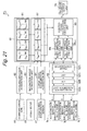
  • Fig. 23 illustrates a seventh embodiment of the present invention.
  • the seventh embodiment is characterized in that the controller sets a control gain for the foremost bogie to a different value from control gains for the other coupling bogies. Similar elements of the seventh embodiment to the above-described second embodiment will be identified by the same reference numerals as the second embodiment, and will not be described especially.
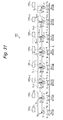
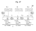
  • a railway train 101 according to the seventh embodiment is configured in such a manner that the n vehicle bodies 2 1 to 2 n coupled by the coupling bogies 4 1 to 4 n-1 are pulled by a locomotive 102.
  • the locomotive 102 can be separated from the passenger vehicles (the number 1 vehicle body to the number n vehicle body) constituted by the vehicle bodies 2 1 to 2 n . Therefore, the number 1 bogie 4 0 of the number 1 vehicle body does not serve as the coupling bogie, and is not located at an end (the front end) of the vehicle body 2 1 .
  • the locomotive 102 and the foremost vehicle body are connected to each other longitudinally inflexibly but vertically flexibly so as to be relatively displaceable in this direction.
  • the number 0 bogie 4 0 supports a half of the vehicle weight of the number 1 vehicle body.
  • the number 1 bogie 4 1 serves as the coupling bogie and therefore supports a sum of a half of the vehicle weight of the number 1 vehicle body and a half of the vehicle weight of the number 2 vehicle body.
  • a vertical force applied to the number 0 bogie 4 0 is weak compared to the other bogies 4 1 to 4 n-1 even in consideration of a shorter length between attachment points of the number 0 bogie 4 0 and the number 1 bogie 4 1 .
  • the railway train 101 includes a controller 103 i substantially similar to the controller 32 i according to the second embodiment, the controller 103 0 for the foremost bogie 4 0 sets the control gain for the foremost bogie 4 0 to a low value compared to the control gains for the other coupling bogies 4 1 to 4 n-1 .
  • a vertical force applied to the last bogie 4 n at the tail end is also weak compared to the other coupling bogies 4 1 to 4 n-1 in a similar manner to the foremost bogie 4 0 . Therefore, the controller 103 n for the last bogie 4 n at the tail end sets a control gain for the last bogie 4 n at the tail end to a low value compared to the control gains for the other coupling gains 4 1 to 4 n-1 .
  • the seventh embodiment can also acquire a similar result and effect to the second embodiment.
  • the control gains for the foremost and last bogies 4 0 and 4 n are set to lower values than the control gains for the other coupling bogies 4 1 to 4 n-1 , whereby the controllers 103 0 and 103 n can calculate control force instructions u 0 and u n according to the vertical forces applied to the bogies 4 0 and 4 n , thereby improving the ride comfort of the railway train 101.
  • the seventh embodiment has been described based on the example in which the locomotive 102 and the number 1 vehicle body are flexibly connected to each other.
  • the present invention is not limited thereto.
  • a locomotive 112 and the number 1 vehicle body may be connected vertically inflexibly so as to be unable to be vertically displaced relative to each other.
  • the railway train 111 according to the second modification includes a controller 113 i substantially similar to the controller 32 i according to the second embodiment.
  • a controller 113 0 for the foremost bogie 4 0 sets the control gain for the foremost bogie 4 0 to a higher value than the control gains for the other bogies 4 1 to 4 n .
  • the seventh embodiment has been described based on the example in which the number 1 passenger vehicle is connected to the locomotive 102.
  • the present invention is not limited thereto.
  • the seventh embodiment may be applied to a train that is not pulled by the locomotive.
  • the railway train 121 is configured in such a manner that power devices 122 including such as motors are distributed to the respective passenger vehicles.
  • the foremost bogie 4 0 (the number 0 bogie) of the passenger vehicle is the foremost bogie of the entire railway train.
  • the number 0 bogie 4 0 supports only a half of the weight of the number 1 vehicle body
  • the number 1 bogie 4 1 supports a sum of a half of the weight of the number 1 vehicle body and a half of the weight of the number 2 vehicle body.
  • a driver's platform is installed on the foremost vehicle body (the number 1 vehicle body), whereby it is highly likely that the number 1 vehicle body has a different vehicle weight and a different distance to the bogie from the other passenger vehicles.
  • the railway train 121 according to the third modification includes a controller 123 i substantially similar to the controller 32 i according to the second embodiment.
  • a controller 123 0 for the foremost bogie 4 0 sets the control gain for the foremost bogie 4 0 to a different value from the control gains for the other coupling bogies 4 1 to 4 n-1 in comprehensive consideration of the influence therefrom.
  • the control gain for the foremost bogie 4 0 is set to a low value when the vertical force applied to the number 0 bogie 4 0 is weak compared to the other coupling bogies 4 1 to 4 n-1 .
  • the control gain for the foremost bogie 4 0 is set to a large value when the vertical force applied to the number 0 bogie 4 0 is strong compared to the other coupling bogies 4 1 to 4 n-1 due to the influence of the driver's platform or the like
  • the seventh embodiment also sets the control gain for the last bogie 4 n to a low value in consideration of the fact that the vertical force applied to the last bogie 4 n is weak compared to the other coupling bogies 4 1 to 4 n-1 .
  • the present invention is not limited thereto.
  • the control gain for the last bogie 4 n may be set to a different value.
  • the railway train 131 according to the fourth modification may be configured in such a manner that a controller 132 n among controllers 132 0 to 132 n sets the control gain for the last bogie 4 n to a different value (for example, a high value) from the control gains for the other coupling bogies 4 1 to 4 n-1 .
  • a specific value of the control gain is appropriately set based on a result of detection of the vibration or the like when the railway train runs actually.
  • the railway train 131 may be configured to be pulled by a locomotive, and may be configured not to be pulled by a locomotive, like the third modification.
  • the seventh embodiment and the second to fourth modifications have been described based on the example in which they are applied to the second embodiment, but may be applied to the first embodiment. Further, the seventh embodiment may be combined with any of the third to sixth embodiments.
  • Figs. 27 and 28 illustrate an eighth embodiment of the present invention.
  • the eighth embodiment is characterized in that the controller calculates vibrations of adjacent two vehicle bodies based on a detection value of a sensor mounted near one of the vehicle bodies. Similar elements of the eighth embodiment to the above-described second embodiment will be identified by the same reference numerals as the second embodiment, and will not be described especially.
  • a railway vehicle 141 according to the eighth embodiment includes the vehicle body 2 i , the coupling portion 3 i , the bogie 4 i , the vertically movable dampers 7, the acceleration sensor 9 i , a controller 143 i , and the like in a substantially similar manner to the railway train 31 according to the second embodiment.
  • the railway vehicle 141 includes an inter-vehicle body displacement sensor 142 i that detects a relative longitudinal displacement between the adjacent vehicle body 2 i and vehicle body 2 i+1 .
  • the inter-vehicle displacement sensor 142 0 is disposed between the number 1 vehicle body 2 1 and the number 2 vehicle body 2 2 , and detects a relative longitudinal displacement X b1,2 therebetween.
  • the inter-vehicle displacement sensor 142 n-1 is disposed between the number n-1 vehicle body 2 n-1 and the number n vehicle body 2 n (the last vehicle body), and detects a relative longitudinal displacement X bn-1,n therebetween.
  • These inter-vehicle displacement sensors 142 0 to 142 n-1 each output a detection signal according to the relative longitudinal displacement X bi , i+1 , which corresponds to a distance between adjacent vehicle bodies.
  • inter-vehicle displacement sensor 142 i will be used to refer to any of the inter-vehicle displacement sensor 142 0 to 142 n-1 .
  • the inter-vehicle displacement sensor 142 i is mounted at a position upward away from the coupling portion 3 i between the number i vehicle body and the number i+1 vehicle body by a distance h.
  • the controller 143 i includes a preprocessing unit (not illustrated) that acquires the accelerations a i-1 and a i from the detection signals of the acceleration sensors 9 i-1 and 9 i , and includes a preprocessing unit (not illustrated) that acquires the relative displacement X bi,i+1 from the detection signal of the inter-vehicle displacement sensor 142 i .
  • the controller 143 i includes a vibration control unit 144 that outputs the number i bogie control force instruction u i according to the instruction values for the actuators 7A based on the accelerations a i-1 and a i and the relative displacement x bi,i+1 .
  • the vibration control unit 144 includes a number i vehicle body vibration calculation unit 145 i that calculates the vibration of the vehicle body 2 i based on the accelerations a i-1 and a i , which are the detection values of the acceleration sensors 9 i-1 and 9 i , a number i+1 vehicle body vibration calculation unit 145 i+1 that calculates the vibration of the vehicle body 2 i+1 based on a result of the calculation of the number i vehicle body vibration calculation unit 145 i and the relative displacement x bi,i+1 , which is the detection value of the inter-vehicle displacement sensor 142 i , and a control force instruction calculation unit 146 that calculates the number i bogie control force instruction u i for the vertically movable dampers 7 of the bogie 4 i based on the vibrations of the vehicle bodies 2 i and 2 i+1 calculated by these vehicle body vibration calculation units 145 1 and 145 i+1 .
  • the control force instruction calculation unit 146 is configured in a substantially similar manner
  • the number i bogie control force instruction u i calculated by the control force instruction calculation unit 146 is input into the number i bogie current output unit 14 i , and the number i bogie current output unit 14 i supplies instruction currents according to the number i bogie control force instruction u i to the actuators 7A of the vertically movable dampers 7 of the bogie 4 i .
  • the vibration of the vehicle body 2 i due to pitching and bouncing is damped, whereby the ride comfort of the vehicle body 2 i can be improved.
  • the relative displacement x bi,i+1 detected by the inter-vehicle displacement sensor 142 i is defined with use of the distance h between the inter-vehicle displacement sensor 142 i and the coupling portion 3 i in the following manner.
  • the relative displacement x bi,i+1 is zero when the pitching angles ⁇ i and ⁇ i+1 of the number i and i+1 vehicle bodies are equal to each other.
  • x bi , i + 1 sin ⁇ i - ⁇ i + 1 ⁇ h
  • a relative angle ( ⁇ i - ⁇ i+1 ) between the number i vehicle body and the number i+1 vehicle body is calculated from the output (the relative displacement ⁇ bi,i+1 ) of the inter-vehicle displacement sensor 142 i according to the following conversion equation. ⁇ i - ⁇ i + 1 ⁇ x bi , i + 1 h
  • the pitching angular acceleration (d2 ⁇ i /dt2) of the number i vehicle body is calculated by an equation 33.
  • ⁇ ⁇ i a i - a i - 1 L i
  • the pitching angular acceleration (d2 ⁇ i+1 /dt2) of the number i+1 vehicle body is calculated in the following manner. ⁇ ⁇ i + 1 ⁇ a i - a i - 1 L i - x ⁇ bi , i + 1 h
  • the vertical accelerations (d2z Bi/ dt2) and (d2z Bi+1 /dt2) of the number i and i+1 vehicle bodies are calculated based on the acceleration a i-1 acquired by the acceleration sensor 9 i-1 and the acceleration a i acquired by the acceleration sensor 9 i by the following equation.
  • z ⁇ Bi a i + a i - 1 2
  • z ⁇ Bi + 1 a i + L i + 1 2 ⁇ ⁇ ⁇ i + 1
  • the above-described calculations allow pitching and bouncing of the number i vehicle body and the number i+1 vehicle body to be acquired only from the accelerations a i-1 and a i of the number i vehicle and the displacement x bi,i+1 between the vehicle bodies directly above the number i bogie 4 i .
  • the acceleration a i can be expressed by the vertical acceleration (d2z Bi /dt2) and the pitching angular acceleration (d2 ⁇ i /dt2) of the number i vehicle body. Therefore, pitching and bouncing of the number i+1 vehicle body can be acquired based on pitching and bouncing of the number i vehicle body and the displacement x bi,i+1 between the vehicle bodies.
  • the acceleration sensor 9 i-1 and the acceleration sensor 9 i correspond to the first vibration detector that detects the vibration of the vehicle body 2 i , together with the number i vehicle body vibration calculation unit 145 i of the controller 143 i .
  • the first vibration detector and the inter-vehicle displacement sensor 142 i correspond to the second vibration detector that detects the vibration of the vehicle body 2 i+1 , together with the number i+1 vehicle body vibration calculation unit 145 i+1 of the controller 143 i .
  • the number i+1 vehicle body vibration calculation unit 145 i+1 may calculate the vibration of the vehicle body 2 i+1 by substituting the accelerations a i-1 and a i , which are the detection values of the acceleration sensors 9 i-1 and 9 i , and the displacement x bi,i+1 between the vehicle bodies, which is the detection value of the inter-vehicle displacement sensor 142 i into the equations 34 and 36 without using the detection value of the first vibration detector.
  • the eighth embodiment can also acquire a similar result and effect to the second embodiment. Further, the eighth embodiment realizes control for reducing the vibrations of the vehicle body 2 i and the adjacent vehicle body 2 i+i in a similar manner to the second embodiment while using only the wiring for the vehicle body 2 i . Therefore, it is possible to acquire a control effect close to the second embodiment with a smaller calculation amount of the controller 143 i and a simpler configuration.
  • the inter-vehicle displacement sensor 142 i detects the relative longitudinal displacement x bi,i+1 , and then calculates the relative angle ( ⁇ i - ⁇ i+1 between the vehicle bodies.
  • the present invention is not limited thereto, and the inter-vehicle displacement sensor may directly detect the relative angle ( ⁇ i - ⁇ i+1 ) between the vehicle bodies.
  • the vehicle body 2 i detects the vibration of the vehicle body 2 i such as pitching and bouncing with use of the acceleration sensors 9 i-1 and 9 i mounted on the front end and the rear end.
  • the positions of the acceleration sensors 9 i1 and 9 i , and the directions in which the accelerations are detected are not limited thereto, and may be arbitrarily changed.
  • the eighth embodiment may be combined with any of the third to seventh embodiments.
  • Fig. 29 illustrates a ninth embodiment of the present invention.
  • the ninth embodiment is characterized in that the controller calculates the control force of the coupling bogie based on the control force of the bogie when the vehicle body exits by itself. Similar elements of the ninth embodiment to the above-described second embodiment will be identified by the same reference numerals as the second embodiment, and will not be described especially.
  • a controller 151 i includes a preprocessing unit (not illustrated) that acquires the accelerations a i-1 , a i , and a i+1 from the detection signals of the acceleration sensors 9 i-1 , 9 i , and 9 i+1 .
  • the controller 151 i includes a vibration control unit 152 that outputs the number i bogie control force instruction u i according to the instruction values for the actuators 7A based on the accelerations a i-1 , a i , and a i+1 .
  • the vibration control unit 152 includes a number i vehicle body vibration calculation unit 153 i , a number i+1 vehicle body vibration calculation unit 153 i+1 , and a control force instruction calculation unit 154.
  • the number i vehicle body vibration calculation unit 153 i is configured in a substantially similar manner to the number i vehicle body vibration calculation unit 34 i according to the second embodiment, and calculates the vibration of the vehicle body 2 i based on the accelerations a i-1 and a i , which are detection values of the acceleration sensors 9 i _ l and 9 i .
  • the number i+1 vehicle body vibration calculation unit 153 i+i is configured in a substantially similar manner to the number i+1 vehicle body vibration calculation unit 34 i+i according to the second embodiment, and calculates the vibration of the vehicle body 2 i+1 based on the accelerations a i and a i+1 , which are detection values of the acceleration sensors 9 i and 9 i+1 .
  • the control force instruction calculation unit 154 calculates the number i bogie control force instruction u i based on the vibrations of the vehicle bodies 2 i and 2 i+1 .
  • This control force instruction calculation unit 154 includes a number i vehicle body control force instruction calculation unit 155 i , a number i+1 vehicle body control force instruction calculation unit 155 i+1 , and an addition unit 156.
  • the number i vehicle body control force instruction calculation unit 155 i calculates control force instructions u iF and u iR for reducing the vibration of the vehicle body 2 i by bogies 4 iF and 4 iR , assuming that the vehicle body 2 i is a non-coupled independent vehicle with the bogies 4 iF and 4 iR disposed on the front and rear sides thereof. More specifically, the number i vehicle body control force instruction calculation unit 155 i calculates a number i vehicle body front side control force instruction u iF for the vertically movable dampers 7 of the bogie 4 iF virtually disposed on the front side of the vehicle body 2 i based on the vibration of the vehicle body 2 i .
  • the number i vehicle body control force instruction calculation unit 155 i calculates a number i vehicle body rear side control force instruction u iR for the vertically movable dampers 7 of the bogie 4 iR virtually disposed on the rear side of the vehicle body 2 i based on the vibration of the vehicle body 2 i .
  • the number i+1 vehicle body control force instruction calculation unit 155 i+i calculates control force instructions u i+1F and u i+1R for reducing the vibration of the vehicle body 2 i+i by bogies 4 i+1F and 4 i+R , assuming that the vehicle body 2 i+1 is a non-coupled independent vehicle with the bogies 4 i+1F and 4 i+1R disposed on the front and rear sides of the vehicle body 2 i+1 .
  • the number i+1 vehicle body control force instruction calculation unit 155 i+1 calculates a number i+1 vehicle body front side control force instruction u i+1F for the vertically movable dampers 7 of the bogie 4 i+1F virtually disposed on the front side of the vehicle body 2 i+1 based on the vibration of the vehicle body 2 i+1 .
  • the number i+1 vehicle body control force instruction calculation unit 155 i+1 calculates a number i+1 vehicle body rear side control force instruction u i+1R for the vertically movable dampers 7 of the bogie 4 i+1R virtually disposed on the rear side of the vehicle body 2 i+1 based on the vibration of the vehicle body 2 i+1 .
  • the addition unit 156 adds the number i vehicle body rear side control force instruction u iR calculated by the number i vehicle body control force instruction calculation unit 155 i and the number i+1 vehicle body front side control force instruction u i+1F calculated by the i+1 vehicle body control force instruction calculation unit 155 i+1 , and calculates the number i bogie control force instruction u i for the vertically movable dampers 7 of the coupling bogie 4 i disposed between the number i vehicle body and the number i+1 vehicle body.
  • the number i control force instruction u i calculated by the control force instruction calculation unit 154 is input into the number i bogie current output unit 14 i , and the number i bogie current output unit 14 i supplies instruction currents according to the number i bodie control force instruction u i to the actuator 7As of the vertically movable dampers 7 of the bogie 4 i .
  • the vibration of the vehicle body 2 i due to pitching and bouncing is damped, whereby the ride comfort of the vehicle body 2 i can be improved.
  • control force instruction calculation unit 154 Next, a control law used by the control force instruction calculation unit 154 will be described.
  • the number i vehicle body control force instruction calculation unit 155 i calculates the control force u iF for the vertically movable dampers 7 of the front bogie 4 iF of the number i vehicle body and the control force u iR for the vertically movable dampers 7 of the rear bogie 4 iR of the number i vehicle body based on the vertical displacement z Bi and the pitching angle ⁇ i of the number i vehicle body 2 i in the following manner.
  • u iF u iR A iF B iF C iF D iF A iR B iR C iR D iR ⁇ z ⁇ Bi z Bi ⁇ ⁇ i ⁇ i
  • Gains A iF to D iF and A iR to D iR are determined, for example, by the Skyhook control, the LQG control, or the like performed against pitching and bouncing of the number i vehicle body 2 i .
  • the number i+1 vehicle body control force instruction calculation unit 155 i+1 calculates the control force u i+1F for the vertically movable dampers 7 of the front bogie 4 i+1F of the number i+1 vehicle body, and the control force u i+1R for the vertically movable dampers 7 of the rear bogie 4 i+1R of the number i+1 vehicle body in the following manner.
  • the coupling bogie 4 i serves as both the rear bogie 4 iR of the number i vehicle body and the front bogie 4 i+1F of the number i+1 vehicle body. Therefore, the addition unit 156 of the control force instruction calculation unit 154 calculates the control force u i for the number i bogie 4 i from a sum of the control force u i p for the rear bogie 4 i of the number i vehicle body and the control force u i+lF for the front bogie 4 i+iF of the number i+1 vehicle body, as indicated by the following equation, an equation 39.
  • u i u iR + u i + 1 ⁇ F
  • an equation 40 can be acquired by combining the above-described equations 37 to 39.
  • u i A iR ⁇ z ⁇ Bi + A i + 1 ⁇ F ⁇ z ⁇ Bi + 1 + B iR ⁇ z Bi + B i + 1 ⁇ F ⁇ z Bi + 1 + C iR ⁇ ⁇ ⁇ i + C i + 1 ⁇ F ⁇ ⁇ ⁇ i + 1 + D iR ⁇ ⁇ i + D i + 1 ⁇ F ⁇ ⁇ i + 1
  • This equation 40 has the same form as the recurrence relation of the equation 28 according to the second embodiment.
  • the ninth embodiment corresponds to the second embodiment with the control gains G Ai,i , G Ai, i+1 , G Bi,i , G Bi,i+1 , G ci , i , G Ci,i+1 , G Di,i , and G Di,i+1 replaced by the following manner.
  • the ninth embodiment can acquire a vibration reduction effect close to the second embodiment with the control force u i calculated by the equation 39.
  • the ninth embodiment can determine the control parameters without calculating the above-described high-order optimum feedback.
  • the ninth embodiment can also acquire a similar result and effect to the second embodiment. Further, the ninth embodiment can reduce the calculation amount of the control apparatus 151 i because it eliminates the necessity of calculating the high-order optimum feedback.
  • the ninth embodiment may be combined with any of the third to eighth embodiments.
  • Figs. 31 and 32 illustrate a tenth embodiment of the present invention.
  • the tenth embodiment is characterized in that the controller calculates the control force of the coupling bogie based on vibrations of four vehicle bodies. Similar elements of the tenth embodiment to the above-described second embodiment will be identified by the same reference numerals as the second embodiment, and will not be described especially.
  • a railway train 161 according to the tenth embodiment includes the vehicle body 2 i , the coupling portion 3 i , the bogie 4 i , the vertically movable dampers 7, the acceleration sensor 9 i , a controller 162 i , and the like in a substantially similar manner to the railway train 31 according to the second embodiment.
  • the controller 162 i include a preprocessing unit (not illustrated) that acquires the accelerations a i-2 , a i-1 , a i , a i+1 , and a i+2 from the detection signals of the acceleration sensors 9 i-2 , 9 i-1 , 9 i , 9 i+1 , and 9 i+2 .
  • the controller 162 i includes a vibration control unit 163 that outputs the number i bogie control force instruction u i according to the instruction values for the actuators 7A based on the accelerations a i-2 , a i-1 , a i , a i+1 , and a i+2 .
  • the vibration control unit 163 includes a number i-1 vehicle body vibration calculation unit 164 i-1 , a number i vehicle body vibration calculation unit 164 i , a number i+1 vehicle body vibration calculation unit 164 i+1 , a number i+2 vehicle body vibration calculation unit 164 i+2 , and a control force instruction calculation unit 165.
  • the vehicle body vibration calculation units 164 i-1 , 164i, 164 i+1 , and 164 i+2 are configured in a substantially similar manner to the number i vehicle body vibration calculation unit 12 i according to the first embodiment. Therefore, the vehicle body vibration calculation units 164 i-1 , 164 i , 164 i+1 , and 164 i+2 calculate the vibrations of the vehicle bodies 2 i-1 , 2 i , 2 i+1 , and 2 i+2 based on the equations 1 and 2.
  • the number i-1 vehicle body vibration calculation unit 164 i-1 calculates the vibration of the vehicle body 2 i-1 based on the accelerations a i-2 and a i-1 , which are the detection values of the acceleration sensors 9 i-2 and 9 i-1 .
  • the number i vehicle body vibration calculation unit 164 i calculates the vibration of the vehicle body 2 i based on the accelerations a i-1 and a i , which are the detection values of the acceleration sensors 9 i-1 and 9 i .
  • the number i+1 vehicle body vibration calculation unit 164 i+1 calculates the vibration of the vehicle body 2 i+1 based on the accelerations a i and a i+1 , which are the detection values of the acceleration sensors 9 i and 9 i+1 .
  • the number i+2 vehicle body vibration calculation unit 164 i+2 calculates the vibration of the vehicle body 2 i+2 based on the accelerations a i+1 and a i+2 , which are the detection values of the acceleration sensors 9 i+1 and 9 i+2 .
  • the control force instruction calculation unit 165 calculates the number i bogie control force instruction u i for the vertically movable dampers 7 of the bogie 4 i based on the vibrations of the vehicle bodies 2 i-1 , 2 i , 2 i+1 , and 2 i+2 calculated by these vehicle body vibration calculation units 164 i-1 , 164 i , 164 i+1 , and 164 i+2 .
  • the number i bogie control force instruction u i calculated by the control force instruction calculation unit 165 is input into the number i bogie current output unit 14 i , and the number i bogie current output unit 14 i supplies instruction currents according to the number i bogie control force instruction u i to the actuators 7A of the vertically movable dampers 7 of the bogie 4 i .
  • the vibration of the vehicle body 2 i due to pitching and bouncing is damped, whereby the ride comfort of the vehicle body 2 i can be improved.
  • the railway train 161 configured in the above-described manner controls the damping forces of the vertically movable dampers 7 of the bogie 4 i based on the outputs of the acceleration sensors 9 i-2 , 9 i-1 , 9 i , 9 i+1 , and 9 i+2 according to a control law that will be described next.
  • the control law according to the tenth embodiment is configured basically in a similar manner to the second embodiment. However, this control law is different from the second embodiment in terms of approximating the state feedback K in the following manner.
  • K G A ⁇ G B ⁇ G C ⁇ G D
  • G A G A ⁇ 0 , 1 G A ⁇ 0 , 2 0 0 0 ⁇ 0 0 0 0 0 G A ⁇ 1 , 1 G A ⁇ 1 , 2 G A ⁇ 1 , 3 0 0 0 ⁇ 0 0 0 0 0 G A ⁇ 2 , 1 G A ⁇ 2 , 2 G A ⁇ 2 , 3 G A ⁇ 2 , 4 0 0 ⁇ 0 0 0 0 0 0 G A ⁇ 3 , 2 G A ⁇ 3 , 3 G A ⁇ 3 , 4 G A ⁇ 3 , 5 0 ⁇ 0 0 0 0 0 0 0 0 0
  • the control force u i to be generated at the vertically movable dampers 7 of the number i bogie 4 i is expressed by the following recurrence relation.
  • u i G Ai , i - 1 ⁇ z ⁇ Bi - 1 + G Ai , i ⁇ z ⁇ Bi + G Ai , i + 1 ⁇ z ⁇ Bi + 1 + G Ai , i + 2 ⁇ z ⁇ Bi + 2 + G Bi , i - 1 ⁇ z Bi - 1 + G Bi , i ⁇ z Bi + G Bi , i + 1 ⁇ z Bi + 1 + G Bi , i + 2 ⁇ z Bi + 2 + G Ci , i - 1 ⁇ ⁇ ⁇ i - 1 + G Ci , i ⁇ ⁇ ⁇ i + G Ci , i + 1 ⁇ ⁇ ⁇ i + 1 + G Ci , i + 2 ⁇ ⁇ ⁇
  • the control force u i to be generated at the vertically movable dampers 7 of the number i bogie 4 i is determined based on only the motions of the number i-1 vehicle body, the number i vehicle body, the number i+1 vehicle body, and the number i+2 vehicle body.
  • the controller 162 i is disposed very close to the vertically movable dampers 7, and the controller 162 i determines the control force u i from the acceleration information of the its own vehicle body (the vehicle body 2 i ), the adjacent vehicle body (the vehicle body 2 i+1 ), and the vehicle bodies (the vehicle bodies 2 i-1 and 2 i+2 ) further adjacent to the respective vehicle bodies 2 i and 2 i+1 according to the above-described recurrence relation.
  • the length of the wiring laid in the railway train 161 is increased to a length corresponding to four vehicles, but the performance of the controller 162 i approaches the performance of the controller that calculates the control force in consideration of the vibrations of all of the vehicle bodies (the vehicle bodies 2 1 to 2 n ), like the first embodiment.
  • the tenth embodiment can also acquire a similar result and effect to the second embodiment. Further, the tenth embodiment calculates the control force u i of the bogie 4 i based on the vibrations of the two vehicle bodies and the two vehicle bodies respectively on the opposite front and rear sides of the bogie 4 i , i.e., the total four vehicle bodies of the vehicle bodies 2 i-1 , 2 i , 2 i+1 , and 2 i+2 , thereby succeeding in acquiring a vibration reduction effect close to the control in consideration of the vibrations of all of the vehicle bodies (the vehicle bodies 2 1 to 2 n ).
  • the tenth embodiment calculates the control force u i of the bogie 4 i based on the vibrations of the four vehicle bodies 2 i-1 , 2i, 2 i+1 , and 2 i+2 .
  • the controller may calculate the control force u i of the bogie 4 i based on vibrations of six vehicle bodies, or may calculate the control force u i of the bogie 4 i based on vibrations of eight vehicle bodies.
  • the controller does not necessarily have to calculate the control force based on vibrations of vehicle bodies corresponding to an even number, and may calculate the control force u i of the bogie 4 i based on vibrations of three or more vehicles corresponding to an odd number.
  • the present embodiment can be realized by calculating the control force u i of the bogie 4 i without using a vibration of at least one vehicle body located away from the bogie 4 i that is the control target, among the n vehicle bodies 2 1 to 2 n .
  • a vehicle body located away from the bogie 4 i is preferentially set as the vehicle body that is not used in the calculation of the control force u i , because this is a vehicle body less influential on the control force u i of the bogie 4 i .
  • the tenth embodiment may be combined with any of the third to ninth embodiments.
  • Figs. 33 and 34 illustrate an eleventh embodiment of the present embodiment.
  • the eleventh embodiment is characterized in that the coupling bogie is provided with vertically movable dampers independently respectively mounted between the bogie and the vehicle body in front of the bogie, and between the bogie and the vehicle body behind the bogie. Similar elements of the eleventh embodiment to the above-described second embodiment will be identified by the same reference numerals as the second embodiment, and will not be described especially.
  • a railway train 171 according to the eleventh embodiment includes the vehicle body 2 i , the coupling portion 3 i , the bogie 4 i , vertically movable dampers 172 iF and 172 iR , the acceleration sensor 9 i , a controller 173 i , and the like in a substantially similar manner to the railway train 31 according to the second embodiment.
  • the vertically movable damper 172 iF corresponds to the cylinder apparatus, and is disposed between the vehicle body 2 i and the bogie 4 i on each of the right and left sides at the front of the bogie 4 i .
  • the vertically movable damper 172 iF is configured in a similar manner to the vertically movable damper 7, and includes the actuator 7A.
  • a control signal (an instruction current) according to a number i bogie front side control force instruction u iF is supplied from the control apparatus 173 i into the actuator 7A of the vertically movable damper 172 iF .
  • the damping force of the vertically movable damper 172 iF is variably controlled according to the control signal.
  • the vertically movable damper 172 iR corresponds to the cylinder apparatus, and is disposed between the vehicle body 2 i+1 and the bogie 4 i on each of the right and left sides at the rear of the bogie 4 i .
  • the vertically movable damper 172 iR is configured in a similar manner to the vertically movable damper 7, and includes the actuator 7A.
  • a control signal (an instruction current) according to a number i bogie rear side control force instruction u iR is supplied from the control apparatus 173 i into the actuator 7A of the vertically movable damper 172 iR .
  • the damping force of the vertically movable damper 172 iR is variably controlled according to the control signal.
  • the control apparatus 173 i is configured in a substantially similar manner to the control apparatus 32 i according to the second embodiment, and includes the vibration control unit 33. However, the control apparatus 173 i includes a division unit 174 that divides the number i bogie control force instruction u i output from the vibration control unit 33 into the number i bogie front side control force instruction u iF and the number i bogie rear side control force instruction u R .
  • the bogie 4 i directly supports the vehicle body 2 i on the front side of the bogie 4 i and the vehicle body 2 i+1 on the rear side of the bogie 4 i with use of the vertically movable dampers 172 iF and 172 iR , respectively.
  • the vertically movable dampers 172 iF and 172 iR output respectively different control forces, this results in application of a moment for causing pitching of the bogie 4 i onto the bogie 4 i , thereby leading to the possibility of deteriorating a road-hugging property of the bogie 4 i to affect a braking distance.
  • the vehicle bodies are vertically inflexibly coupled to each other, whereby the vertically movable dampers 172 iF and 172 iR on the front side and the rear side have substantially equal stroke speeds and amounts. Therefore, supplying instructions in such a manner that the vertically movable dampers 172 iF and 172 iR on the front side and the rear side have equal damping coefficients allows the respective dampers to generate substantially equal damping forces.
  • the division unit 174 sets each of the control force instructions u iF and u iR to be supplied to the vertically movable dampers 172 iF and 172 iR on the front side and the rear side to a half of the number i bogie control force instruction u i .
  • the number i bogie front side control force instruction u iF is input into a number i bogie front side current output unit 175 iF
  • the number i bogie rear side control force instruction u iR is input into a number i bogie rear side current output unit 175 iR .
  • These current output units 175 iF and 175 iR supply instruction currents according to the control force instructions u iF and u iR to the vertically movable dampers 172 iF and 172 iR of the bogie 4 i .
  • the eleventh embodiment can also acquire a similar result and effect to the second embodiment.
  • the eleventh embodiment is configured in such a manner that the pneumatic springs 5 are provided between the bogie 4 i and the coupling portion 3 i .
  • the pneumatic springs 5 may be provided between the bogie 4 i and the vehicle bodies 2 i and 2 i+1 , respectively, like a railway train 181 according to a fifth modification illustrated in Fig. 35 .
  • the eleventh embodiment may be applied to the first embodiment, and may be combined with any of the third to tenth embodiments.
  • Fig. 36 illustrates a twelfth embodiment of the present invention.
  • the twelfth embodiment is characterized in that the controller also performs vibration reduction control even against rolling of the vehicle body. Similar elements of the twelfth embodiment to the above-described second embodiment will be identified by the same reference numerals as the second embodiment, and will not be described especially.
  • a controller 191 i according to the twelfth embodiment is configured in a substantially similar manner to the controller 32 i according to the second embodiment, and includes the vibration control unit 33.
  • the controller 191 i includes a rolling vibration control unit 192 that outputs control force instructions u irollL and u irollR for reducing rolling of the vehicle bodies 2 i and 2 i+1 , a left side control force instruction calculation unit 193 L that calculates a number i bogie left side control force instruction u imixL based on the number i bogie control force instruction u i and the control force instruction u irollL , and a right side control force instruction calculation unit 193 R that calculates a number i bogie right side control force instruction u imixR based on the number i bogie control force instruction u i and the control force instruction u irollR .
  • the rolling vibration control unit 192 detects rolling of the vehicle bodies 2 i and 2 i+1 with use of, for example, acceleration sensors (
  • the number i bogie control force instruction u i is a sum of the control forces for the vertically movable dampers 7 mounted on the left and right sides of the bogie 4 i . Therefore, the control force instruction calculation units 193 L and 193 R calculate the number i bogie left side control force instruction u imixL for the vertically movable damper 7 on the left side of the number i bogie 4 i , and the number i bogie right side control force instruction u imixR for the vertically movable damper 7 on the right side of the number i bogie 4 i based on the following equations, respectively.
  • u imixL u irollL + u i 2
  • u imixR u irollR + u i 2
  • the number i bogie left side control force instruction u imixL is input into a number i bogie left side current output unit 194 iL
  • the number i bogie right side control force instruction u imixR is input into a number i bogie right side current output unit 194 iR .
  • These current output units 194 iL and 194 iR supply instruction currents according to the control force instructions u imixL and u imixR to the vertically movable damper 7 on the left side of the bogie 4 i and the vertically movable damper 7 on the right side of the bogie 4 i , respectively.
  • the twelfth embodiment can also acquire a similar result and effect to the second embodiment.
  • the twelfth embodiment can also reduce rolling in addition to pitching and bouncing of the vehicle body 2 i .
  • the equations 48 and 49 are formulated with weights for rolling and the vertical vibration set substantially equally to each other.
  • these weights for addition may be arbitrarily changed.
  • the control targets are set to three degree of freedom, i.e., the two degrees of freedom of vibrations, bouncing and pitching with rolling added thereto.
  • the present invention is not limited thereto.
  • the controller may be configured to deal with a higher-order motion equation established by adding rolling and yawing of the vehicle body and a motion of the bogie, thereby controlling the ride comfort by applying the present invention while reducing other vibration modes than the vertical vibration.
  • the twelfth embodiment may be applied to the first embodiment, and may be combined to any of the third to eleventh embodiments.
  • the coupling bogie 4 i is disposed at the coupling portion 3 i that couples the two vehicle bodies 2 i and 2 i+1 .
  • the present invention is not limited thereto.
  • a coupling bogie 202 i may be disposed at a different position form the coupling portion 3 i , like a railway train 201 according to a sixth modification illustrated in Fig. 37 .
  • the coupling bogie 202 i is mounted under the vehicle body 2 i at the rear end of the vehicle body 2 i , which is an end of the vehicle body 2 i closer to the vehicle body 2 i+1 adjacent to the vehicle body 2 i , and supports the vehicle body 2 i and the like via spring members such as the pneumatic springs 5.
  • the coupling bogie 4 i includes four wheels 6, but may include two wheels 6, like the coupling bogie 202 i .
  • the vertically movable damper 7 is a semi-active damper, but may use an active damper (any of an electric actuator and a hydraulic actuator) instead of the semi-active damper.
  • Use of the active damper can further effectively improve the ride comfort.
  • the controllers 10, 22, 32 i , 41 i , 51 i , 71 i , 81 i , 103 i , 113 i , 123 i , 132 i , 143 i , 151 i , 162 i , 173 i , and 191 i reduce the vertical vibration of the vehicle body 2 i such as bouncing and pitching, but may reduce a lateral vibration of the vehicle body 2 i .
  • the controller calculates the instruction value for the actuator based on the detection value of the first vibration detector configured to detect the vibration of the first vehicle body and the detection value of the second vibration detector configured to detect the vibration of the second vehicle body. Therefore, it is possible to control the vertically movable damper of the bogie in consideration of influence of the vehicle bodies on each other even when the plurality of vehicle bodies coupled to each other via the coupling bogie is influentially linked to each other. As a result, it is possible to reduce the vibration of the vehicle body in the entire coupling bogie train including the plurality of vehicle bodies to improve the ride comfort.
  • one or more vehicle bodies are further additionally coupled to the first vehicle body and/or the second vehicle body.
  • the controller calculates the instruction value for the actuator without using a vibration of at least one vehicle body located away from the coupling portion among the added vehicle bodies. Therefore, it is possible to reduce the length of the cable that connects the various kinds of sensors and the vertically movable damper to the control apparatus, compared to, for example, controlling the vibration based on the vibrations of all of the vehicle bodies, thereby realizing simplification of the wiring layout and a reduction in a noise. In addition thereto, it is possible to simplify the ride comfort control calculation, thereby reducing the manufacturing cost.
  • the railway train further includes another cylinder apparatus disposed between the coupling bogie and the second vehicle body and configured to exert an application force adjustable by another actuator, and the controller calculates the instruction value for the other actuator based on the detection value of the first vibration detector and the detection value of the second vibration detector.
  • the controller includes the high-pass filter configured to remove a component of a lower frequency than a resonance point of bouncing and pitching of the first and second vehicle bodies from the detection value of the first vibration detector and the detection value of the second vibration detector. Therefore, it is possible to remove the component of a gradual acceleration change, for example, like a change in a slope of a road surface, from the detection values of the first and second vibration detectors, thereby providing control against only a vibration such as pitching and bouncing. As a result, it is possible to prevent the cylinder apparatus from generating an unnecessary application force on an ascending slope tack or a descending slope track, thereby improving the ride comfort on the ascending slope track and the like.
  • the railway train further includes the inter-vehicle displacement sensor configured to detect the inter-vehicle displacement between the first vehicle body and the second vehicle body.
  • the second vibration detector calculates the vibration of the second vehicle body based on the detection value of the first vibration detector and the detection value of the inter-vehicle displacement sensor. Therefore, it is possible to detect the vibrations of the first and second vehicle bodies with use of the first vibration detector and the inter-vehicle displacement sensor disposed about the first vehicle body.

Landscapes

  • Engineering & Computer Science (AREA)
  • Mechanical Engineering (AREA)
  • Vehicle Body Suspensions (AREA)

Abstract

A vehicle body 2i and a vehicle body 2i+1 are coupled to each other via a coupling portion 3i. A bogie 4i is disposed under the coupling portion 3i, and a vertically movable damper 7 coupled to the bogie 4i and the coupling portion 3i is mounted on each of both lateral sides of the bogie 4i. A damping force of the vertically movable damper 7 is controlled by an actuator 7A. An acceleration sensor 9i for detecting a vertical vibration is mounted at a position directly above the bogie 4i. A controller 10 detects vibrations of the vehicle bodies 2i and 2i+1 with use of detection signals from the acceleration sensors 9i-1, 9i, and 9i+1, and calculates a number i bogie control force instruction ui for the vertically movable damper 7 of the bogie 4i in consideration of vibrations of all of the vehicle bodies 21 to 2n.

Description

  • The present invention relates to a suspension control system preferably used to reduce a vibration or the like of a railway train.
  • Railway trains that run on railway tracks less requiring a change in the number of connected vehicles may employ a method in which a bogie is disposed at a portion coupling vehicles to each other, and the adjacent two vehicle bodies are supported by the single bogie. Such a bogie is referred to as a coupling bogie (Jacobs bogie), and a railway train employing the coupling bogie is referred to as a coupling bogie train. The coupling bogie train has an advantage of facilitating a favorable design in terms of a vehicle's movement such as reducing a noise in a passenger vehicle because the bogie is located away from the passenger vehicle, lowering the vehicle's center of gravity, and raising the position where a secondary suspension is supported, compared to a railway train that is not the coupling bogie train.
  • Further, for example, Japanese Patent Application Public Disclosure No. 2012-76553 discusses an invention configured in such a manner that a cylinder apparatus such as a damping force adjustable shock absorber is provided between a vehicle body and a bogie of a railway train, and a damping force characteristic of the cylinder apparatus is variably controlled according to a control signal (a control current).
  • The configuration discussed in Japanese Patent Application Public Disclosure No. 2012-76553 is applied to the railway train that is not the coupling bogie train. In the railway train that is not the coupling bogie train, vehicle bodies are flexibly coupled to each other so as to be vertically displaceable relative to each other therebetween. Therefore, a vertical vibration of the vehicle body is less affected by a vertical vibration of the adjacent vehicle body. Further, vertically movable dampers of bogies disposed at front and rear sides are connected to only their own vehicle body. Therefore, the vibration of the vehicle body can be reduced by controlling the vertically movable dampers to generate damping forces for damping the vibration of only their own vehicle body.
  • On the other hand, in the coupling bogie train, the vehicle bodies are inflexibly coupled to each other by a connection portion (coupling portion) so as to be unable to be vertically displaced relative to each other therebetween, and a vertical vibration of the vehicle body is highly affected by a vertical vibration of the adjacent vehicle body. Therefore, all vehicle bodies coupled by coupling bodies are influentially linked to one another, and vertically movable dampers should be in charge of absorption of vibrations of these vehicle bodies. As a result, there is raised such a problem that only controlling the vertically movable damper to generate a damping force for reducing a vibration of its own vehicle body, like the conventional technique, cannot sufficiently reduce the vibration of the vehicle body actually.
  • The present invention has been contrived in consideration of the above-described problem with the conventional technique, and an object thereof is to provide a suspension control system capable of reducing a vibration of the coupling bogie train.
  • To achieve the above-described object, according to an aspect of the present invention, a suspension control system includes a coupling portion configured to couple at least two vehicle bodies and connect a first vehicle body and a second vehicle body adjacent to each other in such a manner that a driving force can be transmitted therebetween, a coupling bogie configured to provide a support on at least a second vehicle body side of the first vehicle body via a spring member, a cylinder apparatus disposed between the coupling bogie and the first vehicle body and configured to exert an application force adjustable by an actuator, a controller configured to control the actuator, a first vibration detector configured to detect a vibration of the first vehicle body, and a second vibration detector configured to detect a vibration of the second vehicle body. The controller calculates an instruction value for the actuator based on a detection value of the first vibration detector and a detection value of the second vibration detector.
  • According to the present invention, it is possible to reduce a vibration of the coupling bogie train.
    • Fig. 1 is a front view illustrating a railway train that employs a suspension control system according to a first embodiment of the present invention.
    • Fig. 2 schematically illustrates the railway train according to the first embodiment.
    • Fig. 3 illustrates a positional relationship among a coupling portion, a bogie, a vertically movable damper, and the like illustrated in Fig. 1.
    • Fig. 4 is a block diagram illustrating a controller according to the first embodiment.
    • Fig. 5 illustrates a pitching mode of vehicle bodies.
    • Fig. 6 illustrates a bouncing mode of the vehicle bodies.
    • Fig. 7 illustrates a mode generated by combining the pitching mode and bouncing mode of the vehicle bodies.
    • Fig. 8 illustrates a model generated to simulate the railway train according to the first embodiment.
    • Fig. 9 illustrates a coupling force between a bogie corresponding to a bogie number i thereto and the vehicle body.
    • Fig. 10 illustrates a traction force applied to a rear side of a number i vehicle body.
    • Fig. 11 illustrates a force applied in a direction for preventing a relative rotation between the i-th vehicle body and an i+1-th vehicle body.
    • Fig. 12 illustrates a force generated by the relative rotation between the i-th vehicle body and the i+1-th vehicle body.
    • Fig. 13 schematically illustrates a railway train according to a first modification.
    • Fig. 14 schematically illustrates a railway train according to a second embodiment.
    • Fig. 15 is a block diagram illustrating a controller according to the second embodiment.
    • Fig. 16 illustrates characteristic lines that indicate PSD of bouncing of the vehicle body.
    • Fig. 17 illustrates characteristic lines that indicate PSD of pitching of the vehicle body.
    • Fig. 18 is a block diagram illustrating a controller according to a third embodiment.
    • Fig. 19 is a block diagram illustrating a controller according to a fourth embodiment.
    • Fig. 20 is a block diagram illustrating a controller according to a fifth embodiment.
    • Fig. 21 is a block diagram illustrating a controller according to a sixth embodiment.
    • Fig. 22 illustrates a traction force applied to a passenger vehicle while the railway train is running on an ascending slope track
    • Fig. 23 schematically illustrates a railway train according to a seventh embodiment.
    • Fig. 24 schematically illustrates a railway train according to a second modification.
    • Fig. 25 schematically illustrates a railway train according to a third modification.
    • Fig. 26 schematically illustrates a railway train according to a fourth modification.
    • Fig. 27 schematically illustrates a railway train according to an eighth embodiment.
    • Fig. 28 is a block diagram illustrating a controller according to the eighth embodiment.
    • Fig. 29 is a block diagram illustrating a controller according to a ninth embodiment.
    • Fig. 30 illustrates a virtual railway train.
    • Fig. 31 schematically illustrates a railway train according to a tenth embodiment.
    • Fig. 32 is a block diagram illustrating a controller according to the tenth embodiment.
    • Fig. 33 schematically illustrates a railway train according to an eleventh embodiment.
    • Fig. 34 is a block diagram illustrating a controller according to the eleventh embodiment.
    • Fig. 35 schematically illustrates a railway train according to a fifth modification.
    • Fig. 36 is a block diagram illustrating a controller according to a twelfth embodiment.
    • Fig. 37 schematically illustrates a railway train according to a sixth modification.
  • In the following description, suspension control systems according to embodiments of the present invention will be described in detail with reference to the accompanying drawings.
  • Figs. 1 to 4 illustrate a first embodiment of the present invention. Referring to Figs. 1 and 2, a railway train 1 includes a vehicle body 2i, a coupling portion 3i, a bogie 4i, vertically movable dampers 7, an acceleration sensor 9i, a controller 10, and the like. The railway train 1 is a coupling bogie train using coupling bogies by which, for example, n vehicle bodies 21 to 2n are coupled to one another. Such coupling bogies are used for, for example, 50000 series trains provided by Odakyu Electric Railway Co., Ltd., and 300 series trains provided by Enoshima Electric Railway Co.,Ltd.
  • For example, passages and crews are aboard on the vehicle body 2i. Further, a vehicle body 2i-1 is adjacently disposed in front of the vehicle body 2i, and a vehicle bogie 2i+1 is adjacently disposed behind the vehicle body 2i. Therefore, a vehicle body 21 is the foremost vehicle body and a vehicle body 2n is the last vehicle body of the railway train 1 (coupling bogie train) having the n vehicles. Hereinafter, the term "vehicle body 2i" will be used to refer to any one of the vehicle bodies 21 to 2n.
  • The coupling portion 3i couples the vehicle body 2i and the vehicle body 2i+1 in such a manner that a driving force can be transmitted therebetween. The coupling portion 3i couples the vehicle body 2i and the vehicle body 2i+1 by a not-illustrated rubber bush or mechanical link mechanism. As a result, the coupling portion 3i allows the vehicle body 2i and the vehicle body 2i+1 to be bent therebetween to the left or right relative to a traveling direction when the railway train 1 is running on a curved track, and to be bent therebetween in a vertical direction of the railway train 1 when the railway train 1 is entering a slope track.
  • Further, the coupling portion 3i is disposed behind the vehicle body 2i, and a coupling portion 3i-1 is disposed in front of the vehicle body 2i. Therefore, if the railway tray 1 has, for example, n vehicles, a coupling portion 31 is disposed between the vehicle body 21 as a number 1 vehicle body and a vehicle body 22 as a number 2 vehicle body, and a coupling portion 3n-1 is disposed between a vehicle body 2n-1 as a number n-1 vehicle body and the number n vehicle body 2n as the last vehicle body. Hereinafter, the term "coupling portion 3i" will be used to refer to any one of the coupling portions 31 to 3n-1.
  • The coupling portion 3i couples the vehicle body 2i and the vehicle body 2i+1 in such a manner that they are displaced vertically in a same phase by a substantially same amount. In other words, the vehicle body 2i and the vehicle body 2i+1 are vertically inflexibly coupled to each other based on the coupling portion 3i. Therefore, the vehicle body 2i and the vehicle body 2i+1 are vertically displaced at the position of the coupling portion 3i together with each other. It is desirable that the vehicle body 2i and the vehicle body 2i+1 are vertically inflexibly coupled to each other by the coupling portion 3i, i.e., they are coupled to each other so as to be unable to be vertically displaced relative to each other, but they may be allowed to have a slight vertical relative displacement therebetween.
  • The bogie 4i is disposed under the vehicle body 2i or the coupling portion 3i. Bogies 41 to 4n-1 each are a coupling bogie that supports two vehicles such as the vehicle body 2i and the vehicle bogie 2i+1, and are disposed under the coupling portions 31 to 3n-1, respectively. Further, a bogie 40 is disposed under the front side of the foremost vehicle body 21, and the bogie 4n is disposed under the rear side of the last vehicle body 2n. These bogies 40 and 4n each support only a single vehicle such as the vehicle body 21 or 2n. Hereinafter, the term "bogie 4i" will be used to refer to any one of the bogies 40 to 4n.
  • As illustrated in Figs. 1 to 3, the bogie 4i includes pneumatic springs 5, vehicle wheels 6, the vertically movable dampers 7, a traction link (not illustrated), and the like. The bogies 40 and 4n are connected to the vehicle bodies 21 and 2n with use of the traction links. The bogies 41 to 4n-1 are connected to the coupling portions 31 to 3n-1 with use of the traction links. The bogie 4i includes, for example, two axles having the vehicle wheels 6 at both left and right ends thereof, thereby including four vehicle wheels 6 in total. The respective vehicle wheels 6 rotate on left and right rails 8 (only one of them is illustrated), by which the railway train 1 is driven to run along the rails 8, for example, in a direction indicated by an arrow A when being traveling forward.
  • The pneumatic spring 5 is a spring member of the present invention, and corresponds to a secondary suspension mounted on the bogie 4i. The pneumatic springs 5 are, for example, disposed on both sides of the bogie 4i in a lateral direction, and vertically elastically support the coupling portions 31 to 3n-1 and the vehicle bodies 21 and 2n relative to the bogie 4i. These pneumatic springs 5 reduce a vertical vibration between the bogie 4i, and the coupling portions 31 to 3n-1 and the vehicle bodies 21 and 2n.
  • Further, the traction link transmits a traction force and a braking force applied in a longitudinal direction between the bogie 4i, and the coupling portions 31 to 3n-1 and the vehicle bodies 21 and 2n. The traction link is realized with use of a rubber bush or the like so as to allow the coupling portions 31 to 3n-1 and the vehicle bodies 21 and 2n to be displaced (moved) relative to the bogie 4i vertically, laterally, in a yawing direction (when the bogie rotates), and in a pitching direction.
  • The vertically movable dampers 7 are respectively mounted on the right and left sides of the bogie 4i between the vehicle bodies 2i and 2n and the bogies 40 and 4n or the coupling portions 31 to 3n-1 and the bogies 41 to 4n-1. The vertically movable dampers 7 are connected via, for example, rubber bushes to the coupling portions 31 to 3n-1 or the vehicle bodies 2i and 2n, and the bogie 4i, respectively. Each of these vertical movable dampers 7 corresponds to a cylinder apparatus configured to exert an individually adjustable damping force serving as an application force (for example, a damping force adjustable hydraulic shock absorber called a semi-active damper), and includes a damping force generation mechanism (not illustrated) that generates the damping force by controlling a flow of hydraulic fluid in the cylinder apparatus.
  • The damping force generation mechanism includes an actuator 7A that generates the damping force by controlling the flow of the hydraulic fluid in the cylinder apparatus. This actuator 7A includes, for example, a flow amount control valve, and continuously adjusts a characteristic of the generated damping force (a damping force characteristic) from a hard characteristic to a soft characteristic. More specifically, the actuator 7A includes, for example, a current control type proportional solenoid valve. Then, the vertically movable damper 7 can adjust the damping force characteristic according to a current value supplied to the actuator 7A. The actuator 7A for adjusting the damping force does not necessarily have to adjust the damping force characteristic continuously, and may adjust the damping force through two steps or a plurality of steps.
  • Then, the vertically movable damper 7 adjusts the damping force characteristic to an arbitrary characteristic between the hard characteristic and the soft characteristic to reduce a vibration of the vehicle body 2i. More specifically, a control signal (an instruction current) is supplied from the controller 10, which will be described below, to the actuator 7A according to a number i bogie control force instruction ui to reduce pitching and bouncing of the vehicle body 2i, and the damping force of the vertically movable damper 7 is variably controlled according to the control signal. As a result, the vertically movable damper 7 generates a control force for reducing a vertical vibration of the vehicle body 2i.
  • The acceleration sensor 9i is mounted at each of the coupling portions 31 to 3n-1 and the vehicle bodies 21 and 2n. More specifically, the acceleration sensors 91 to 9n-1 are disposed at the coupling portions 31 to 3n-1 at positions corresponding to the bogies 41 to 4n-1, when viewing from above, and detect vertical accelerations a1 to an-1 of the coupling portions 31 to 3n-1. The acceleration sensor 90 is disposed on the front side of the vehicle body 21 as a position corresponding to the bogie 40, and detects a vertical acceleration a0 of the vehicle body 21 at the position of the bogie 40. The acceleration sensor 9n is disposed on the rear side of the vehicle body 2n as a position corresponding to the bogie 4n, and detects a vertical acceleration an of the vehicle body 2n at the position of the bogie 4n. These acceleration sensors 90 to 9n detect the vertical accelerations a0 to an of the coupling portions 31 to 3n-1 and the vehicle bodies 21 and 2n directly above the bogies 40 to 4n, and outputs detection signals according to these accelerations a0 to an. Hereinafter, the term "acceleration sensor 9i" will be used to refer to any one of the acceleration sensors 90 to 9n.
  • For example, suppose that the vehicle body 2i is a first vehicle body, and the vehicle body 2i+1 adjacently disposed behind the vehicle body 2i is a second vehicle body. In this case, the acceleration sensor 9i-1 and the acceleration sensor 9i correspond to a first vibration detector configured to detect a vibration of the vehicle body 2i together with a number i vehicle body vibration calculation unit 12i of the controller 10, which will be described below. Further, the acceleration sensor 9i and the acceleration sensor 9i+1 correspond to a second vibration detector configured to detect a vibration of the vehicle body 2i+1 together with a number i+1 vehicle body vibration calculation unit 12i+1 of the controller 10. In this manner, the acceleration sensor 9i corresponds to a part of the first and second vibration detectors. The second vehicle body does not necessarily have to be a vehicle body disposed behind the first vehicle body, and may be disposed in front of the first vehicle body.
  • The controller 10 includes, for example, a microcomputer, and the acceleration sensor 9i is connected to an input side of the controller 10. Further, the actuators 7A of the vertically movable dampers 7 of each bogie 4i are connected to an output side of the controller 10. Then, the controller 10 generates the number i bogie control force instruction ui, which serves as a damping force instruction signal for the vertically movable dampers 7 of each bogie 4i based on a detection signal from the acceleration sensor 9i, thereby variably controlling the damping forces of the vertically movable dampers 7.
  • As illustrated in Fig. 4, the controller 10 includes a preprocessing unit (not illustrated) that includes an AD converter, a filter processor, and the like, and acquires the acceleration ai from the detection signal of the acceleration sensor 9i. The controller 10 further includes a vibration control unit 11 that outputs the number i bogie control force instruction ui according to instruction values for the actuators 7A based on the acceleration ai.
  • The vibration control unit 11 includes the number i vehicle body vibration calculation unit 12i that calculates the vibration of the vehicle body 2i based on the acceleration ai, which is the detection value of the acceleration sensor 9i, and a control force instruction calculation unit 13 that calculates the number i bogie control force instruction ui for the vertically movable dampers 7 of each bogie 4i based on the vibration of the vehicle body 2i calculated by the number i vehicle body vibration calculation unit 12i. In this case, the number i vehicle body vibration calculation unit 12i calculates the vibration of the vehicle body 2i based on the detection signal from the acceleration sensor 9i-1 and the detection signal from the acceleration sensor 9i. Therefore, the vibration control unit 11 includes a number 1 vehicle body vibration calculation unit 121 to a number n vehicle body vibration calculation unit 12n corresponding to the n vehicle bodies 21 to 2n. Hereinafter, the term "number i vehicle body vibration calculation unit 12i" will be used to refer to any one of the number 1 vehicle body vibration calculation unit 121 to the number n vehicle body vibration calculation unit 12n.
  • The control force instruction calculation unit 13 calculates the number i bogie control force instruction ui according to a control law, which will be described below. Then, the number i bogie control force instruction ui calculated by the control force instruction calculation unit 13 is input into a number i bogie current output unit 14i, and the number i bogie current output unit 14i supplies instruction currents according to the number i bogie control force instruction ui to the actuators 7A of the vertically movable dampers 7 of the bogie 4i. This results in a reduction in a vibration of the vehicle body 2i due to pitching and bouncing, thereby succeeding in improving the ride comfort of the vehicle body 2i. Hereinafter, the term "number i bogie current output unit 14i" will be used to refer to any of a number 0 bogie current output unit 140 to a number n bogie current output unit 14n. A possible simplest configuration to realize this control is such a configuration that the acceleration sensor is disposed directly above the coupling portion of the vehicle body side to acquire a vertical acceleration of the vehicle body directly above the coupling portion, and the vertically movable damper directly below the coupling portion is controlled so as to reduce a change in the acceleration. However, this configuration can provide only a small effect of improving the ride comfort, because a motion mode such as pitching and bouncing of the vehicle body is not taken into consideration in this configuration.
  • A concept of a vibration mode of the vehicle body 2i in the railway train 1 will be described. Fig. 5 illustrates a concept of a pitching mode of the vehicle body 2i. Further, Fig. 6 illustrates a concept of a bouncing mode of the vehicle body 2i. Fig. 7 illustrates a concept of a mode of the vehicle body 2i, which is generated by combining the bouncing vehicle bodies 2i-1 and 2i+1 and the pitching vehicle body 2i. Figs. 5 to 7 illustrate the bouncing mode and the pitching mode respectively independently, but these modes are combined in the vehicle body 2i in actual use.
  • The railway train 1 configured in the above-described manner controls the damping forces of the vertically movable dampers 7 of each bogie 4i based on the output of the acceleration sensor 9i according to the control law that will be described next.
  • To calculate the damping force instruction (the number i bogie control force instruction ui) by the controller 10, a model of the single vehicle body 2i is formulated with the bouncing mode and the pitching mode set as two degrees of freedom, and the control law for the train having n vehicles is developed with use of a 4×n-degree state equation with 2×n degrees of freedom set thereto.
  • A method for calculating the state equation will be described. Fig. 8 illustrates a model generated to simulate the railway train 1 according to the present embodiment. The left side in Fig. 8 corresponds to the traveling direction A of the present model. An X axis, a Z axis, and a Y axis are set so as to represent the traveling direction A (a forward direction), the vertical direction of the vehicle body 2i, and the lateral direction of the vehicle body 2i, respectively (refer to Fig. 3). The present model is established ignoring an elastic vibration of the vehicle body 2i and assuming that both the vehicle body 2i and the bogie 4i are rigid bodies.
  • Main symbols used in this model will be described in a table 1. Unless otherwise indicated, i represents a number of a vehicle body, and the bogie number i is assigned to the bogie 4i disposed behind the number i vehicle body. Therefore, the bogie 41 disposed behind the number 1 vehicle body has a bogie number 1, and the bogie 40 disposed in front of the number 1 vehicle body has a bogie number 0.
  • Further, a dot in equations represents first-order differentiation (d/dt) by time t. Two dots represent second-order differentiation (d2/dt2). Further, suppose that all of the vehicle bodies 21 to 2n have equal lengths (L1 = L2 = ... = Ln = L), and the pneumatic springs 5 have equal stiffnesses on all of the bogies 41 to 4n (k1 = k2 = ... = kn = k). [Table 1]
    SYMBOL QUANTITY REPRESENTED BY SYMBOL
    mi Mass of Number i Vehicle Body(kg)
    n Number of Vehicles (vehicles)
    Li Length of Vehicle Body (m)
    ui Force to be Generated by Vertically Movable Dampers of Number i Bogie (N) (Sum of Control Forces for Vertically Movable Dampers on Left and Right Sides of Bogie)
    ki Stiffness of Pneumatic Springs (Secondary Suspensions) of Number i Bogie (N/m) (Sum of Stiffnesses of Pneumatic Springs on Left and Right Sides of Bogie)
    cr Damping Force against Relative Rotation between Vehicle Bodies ((N•m)/(rad/s))
    kr Stiffness against Relative Rotation between Vehicle Bodies ((N•m)/rad)
    zBi Vertical Displacement of Center of Number i Vehicle Body (m); Positive in Upward Direction
    xBi Longitudinal Displacement of Center of Number i Vehicle Body (m); Positive in Forward Direction
    θi Pitching Angle of Number i Vehicle Body (rad); Positive When Vehicle Body is Plunging Forward
    zTi Vertical Displacement of Number i Bogie (m); Positive in Upward Direction
    Fi Coupling Force between Number i Bogie and Vehicle Body (N); Positive in Upward Direction
    Ti Traction Force Applied to Rear Side of Number i Vehicle Body (Directly Above Number i Bogie) (N); Positive in Backward Direction
    Fri Force Generated by Relative Rotation between Vehicle Bodies (N); Positive in Upward Direction
    I Inertia Moment in Pitching Direction of Number i Vehicle Body
  • Further, the number i vehicle body vibration calculation unit 12i calculates a vertical acceleration (d2zBi/dt2) at a central position of the vehicle body 2i as the vibration of the vehicle body 2i based on an equation 1, and a pitching angular acceleration (d2θi/dt2) based on an equation 2. The equations 1 and 2 are expressed as follows. z ¨ Bi = a i + a i - 1 2
    Figure imgb0001
    θ ¨ i = a i - a i - 1 L i = a i - a i - 1 L
    Figure imgb0002
  • All of the number 1 vehicle body vibration calculation unit 121 to the number n vehicle body vibration calculation unit 12n perform similar calculations. For example, if the vehicle body 2i is the first vehicle body, and the vehicle body 2i+1 is the second vehicle body, the acceleration (d2zBi/dt2) and the pitching angular acceleration (d2θi/dt2) correspond to a vibration of the first vehicle body (the vehicle body 2i), and the acceleration (d2zBi+1/dt2) and the pitching angular acceleration (d2θi+1/dt2) correspond to a vibration of the second vehicle body (the vehicle body 2i+1).
  • The number i vehicle body vibration calculation unit 12i can calculate a vertical speed (dzBi/dt) and the vertical displacement ZBi at the central position of the vehicle body 2i based on the acceleration (d2zBi/dt2), and calculate a pitching angular speed (dθi/dt) and the pitching angle θi at the central position of the vehicle body 2i based on the pitching angular acceleration (d2θi/dt2) by performing an integral calculation or the like.
  • Next, the coupling force Fi, the traction force Ti, and the force Fri generated by a relative rotation of the number i vehicle body are expressed as equations in the following manner. The coupling force Fi is a coupling force between the bogie 4i corresponding to the bogie number i (the number i bogie) and the vehicle body 2i. The traction force Ti is a traction force applied to the rear side of the number i vehicle body (directly above the bogie 4i corresponding to the bogie number i). The force Fri generated by a relative rotation is a force generated by a relative rotation between the vehicle body 2i and the vehicle body 2i+1.
  • The coupling force Fi between the bogie 4i corresponding to the bogie number i and the vehicle body 2i is expressed as illustrated in Fig. 9. In this case, the vertical coupling force Fi between the vehicle body 2i and the bogie 4i is calculated by the following equation as a sum of tensional forces of the pneumatic springs 5 and the damping forces of the vertically movable dampers 7. F i = - k z Bi + L 2 ⁢ sinθ i - z Ti - u i
    Figure imgb0003
  • The coupling force Fi applied to the coupling portion 3i (connection portion) between the number i vehicle body and the number i+1 vehicle body can be expressed in the following manner with use of a force fi(i) applied to the rear end of the number i vehicle body 2i and a force fi(i+1) applied to the front end of the number i+1 vehicle body 2i+1. In the following equation, fa(b) represents a component force of a force applied to a coupling portion 3a corresponding to a bogie number a that is applied to a b-th vehicle body 2b. F i = f i i + f i ⁢ i + 1
    Figure imgb0004
  • In this equation, f0(0) = 0, fn(n+1) = 0
  • Next, the traction force Ti applied to the rear side of the number i vehicle body (directly above the bogie 4i corresponding to the bogie number i) is expressed as illustrated in Fig. 10. In this case, the traction force Ti applied to the number i vehicle body 2i (directly above the bogie 4i corresponding to the bogie number i) is calculated by an equation 5 from a longitudinal inertia force of the vehicle body 2i+1 when the vehicle body 2i is accelerating forward. The equation 5 is formulated ignoring a rolling friction. T i = - ∑ k = i + 1 n m k ⁢ x ¨ Bi
    Figure imgb0005
  • In this equation, Tn = 0
  • In this case, assuming that Tzi represents a Z-direction component of the traction force Ti, the Z-direction component Tzi can be expressed by the following equation, an equation 6. T zi = - T i ⁢ sinθ i + 1
    Figure imgb0006
  • In a multiple-unit system railway train, each vehicle body 2i has a power source, and the traction force Ti is not generated between the vehicle bodies 2i and 2i+1 so that Tzi is zero regardless of whether the train is running on an ascending slope track or is accelerating. Further, if a brake is mounted in each bogie 4i, it is possible to assume that Tzi is zero when the railway train is slowing down regardless of the railway train is a push-pull system or a multiple-unit system. In other words, Tzi is not zero only when a push-pull system railway train is running on an ascending slope track or is accelerating.
  • Next, the force Fri generated by a relative rotation between the vehicle body 2i and the vehicle body 2i+1 is expressed as illustrated in Fig. 12. As illustrated in Fig. 11, when the number i vehicle body is moving in the pitching mode, a force working in a direction for reducing the relative rotation between the number i vehicle body 2i and the number i+1 vehicle body 2i+1 by a spring component kr and a damping component Cr is expressed as a sum of a force fri-1(i) applied to the front end of the number i vehicle body (the coupling portion 3i-1 of the bogie 4i-1 corresponding to the bogie number i-1) perpendicularly to the vehicle body 2i, and a force fri+1(i+1) applied to the rear end of the number i+1 vehicle body (the coupling portion 3i+1 of the bogie 4i+1 corresponding to the bogie number i+1) perpendicularly to the vehicle body 2i+1, around the coupling portion 3i between the number i vehicle body and the number i+1 vehicle body. Then, fra(b) represents a component force of the force applied to the coupling portion 3a corresponding to the bogie number a that is applied to the b-th vehicle body 2b. In this case, the forces fri-1(i) and fri+1(i+1) are expressed by the following equation. f ri - 1 i = f ri + 1 ⁢ i + 1 = 1 L ⁢ - k r ⁢ θ i + 1 - θ i - c r ⁢ θ ˙ i + 1 - θ ˙ i
    Figure imgb0007
  • Therefore, the force Fri generated by a relative rotation between the vehicle bodies is calculated by an equation 8. F ri = cos θ i + 1 - θ i 2 ⁢ f r i i + cos θ i + 1 - θ i 2 ⁢ f ri ⁢ i + 1 f ri i = - k rr ⁢ θ i - θ i - 1 - c rr ⁢ θ ˙ i - θ ˙ i - 1 f ri ⁢ i + 1 = - k rr ⁢ θ i + 2 - θ i + 1 - c rr ⁢ θ ˙ i + 2 - θ ˙ i + 1
    Figure imgb0008
  • In this equation, k rr = 1 L ⁢ k r , c rr = 1 L ⁢ c r
    Figure imgb0009
  • The pitching angle θi is sufficiently small at the vehicle body 2i of the railway train 1 so that this is approximated in the following manner. sin θ 1 ≒ θ i , cos θ i + 1 - θ i 2 ≒ 1
    Figure imgb0010
  • Further, suppose that the railway train 1 runs on a flat land at a constant speed. Therefore, assume that an acceleration in the longitudinal direction is not generated (d2xBi/dt2=0), and the Z-direction component Tzi is also not generated (Tzi = 0) at the center of the vehicle body 2i. In this case, a vertical motion equation of the vehicle body 2i is expressed by an equation 10. Further, a rotational motion equation of the vehicle body 2i is expressed by an equation 11. mi ⁢ z ¨ Bi = 1 2 ⁢ F i + F i - 1 + T zi + T zi - 1 + F ri + F ri - 1 = 1 2 { - k z Bi + L 2 ⁢ θ i - z Ti - u i - k z Bi - 1 + L 2 ⁢ θ i - 1 - z Ti - 1 - u i - 1 + 0 + 0 + - k rr ⁢ θ i - θ i - 1 - c rr ⁢ θ ˙ i - θ ˙ i - 1 - k rr ⁢ θ i + 2 - θ i + 1 - c rr ⁢ θ ˙ i + 2 - θ ˙ i + 1 - k rr ⁢ θ i - 1 - θ i - 2 - c rr ⁢ θ ˙ i - 1 - θ ˙ i - 2 - k rr ⁢ θ i + 1 - θ i - c rr ⁢ θ ˙ i + 1 - θ ˙ i } = 1 2 { - k z Bi + L 2 ⁢ θ i - z Ti - u i - k z Bi - 1 + L 2 ⁢ θ i - 1 - z Ti - 1 - u i - 1 - k rr ⁢ θ i + 2 - θ i - 2 - c rr ⁢ θ ˙ i + 2 - θ ˙ i - 2 }
    Figure imgb0011
    I i ⁢ θ ¨ i = - L 2 [ 1 2 ⁢ F i - 1 + T zi - 1 + F ri - 1 ] + L 2 [ 1 2 ⁢ F i + T zi + F ri ] = - L 2 [ 1 2 { - k z Bi - 1 + L 2 ⁢ θ i - 1 - z Ti - 1 - u i - 1 + 0 - k rr ⁢ θ i - 1 - θ i - 2 - c rr ⁢ θ ˙ i - 1 - θ i - 2 - k rr ⁢ θ i + 1 - θ i - c rr ⁢ θ ˙ i + 1 - θ ˙ i } ] + L 2 [ 1 2 { - k z Bi + L 2 ⁢ θ i - z Ti - u i + 0 - k rr θ i - θ i - 1 - c rr ⁢ θ ˙ i - θ i - 1 - k rr ⁢ θ i + 2 - θ i + 1 - c rr ⁢ θ ˙ i + 2 - θ ˙ i + 1 } ] = L 4 { k z Bi - 1 + L 2 ⁢ θ i - 1 - z Ti - 1 + u i - 1 - k z Bi + L 2 ⁢ θ i - z Ti - u i - k rr ⁢ θ i + 2 - 2 ⁢ θ i + 1 + 2 ⁢ θ i - 2 ⁢ θ i - 1 + θ i + 2 - c rr ⁢ θ ˙ i + 2 - 2 ⁢ θ ˙ i + 1 + 2 ⁢ θ ˙ i - 2 ⁢ θ ˙ i - 1 + θ ˙ i + 2 ]
    Figure imgb0012
  • Then, the following state equation, which has 4×n state amounts, n+1 disturbance inputs, and n+1 control inputs, can be derived from these motion equations. x ˙ = Ax + B 1 ⁢ w + B 2 ⁢ w
    Figure imgb0013
  • In this equation, a state vector x, a disturbance input w, and a control input u (the number i bogie control force instruction ui) have the following contents, respectively. < STATE VECTOR > x = z ˙ B ⁢ 1 z ˙ B ⁢ 2 ⋯ z ˙ Bn z B ⁢ 1 z B ⁢ 2 ⋯ z Bn θ ˙ 1 θ ˙ 2 ⋯ θ ˙ n ⁢ θ 1 ⁢ θ 2 ⋯ θ n T
    Figure imgb0014
    < DISTURBANCE INPUT > w = z T ⁢ 0 ⁢ z T ⁢ 1 ⋯ z Tn T
    Figure imgb0015
    < CONTROL INPUT > u = u 0 ⁢ u 1 ⋯ u n T
    Figure imgb0016
  • Subsequently, the control law is developed with use of this state equation based on LG control by way of example. In this case, for example, the control law can be developed by providing a state feedback K to the state equation so as to minimize an evaluation function J expressed by the following equation. J = ∫ 0 ∞ ⁢ x T ⁢ Qx + u T ⁢ Ru ⁢ dt
    Figure imgb0017
    u = - Kx
    Figure imgb0018
  • The state feedback K acquired at this time is expressed by the following matrix constituted by n rows and 4×n columns. In this case, GA represents a control gain matrix for the vertical speed (dzBi/dt), and GB represents a control gain matrix for the vertical displacement zBi. Further, Gc represents a control gain matrix for the pitching angular speed (dθi/dt), and GD represents a control gain matrix for the pitching angle θ1. K = G A ⁢ G B ⁢ G C ⁢ G D
    Figure imgb0019
    G A = G A ⁢ 0 , 1 G A ⁢ 0 , 2 G A ⁢ 0 , 3 G A ⁢ 0 , 4 G A ⁢ 0 , 5 ⋯ G A ⁢ 0 , n - 3 G A ⁢ 0 , n - 2 G A ⁢ 0 , n - 1 G A ⁢ 0 , n G A ⁢ 1 , 1 G A ⁢ 1 , 2 G A ⁢ 1 , 3 G A ⁢ 1 , 4 G A ⁢ 1 , 5 ⋯ G A ⁢ 1 , n - 3 G A ⁢ 1 , n - 2 G A ⁢ 1 , n - 1 G A ⁢ 1 , n G A ⁢ 2 , 1 G A ⁢ 2 , 2 G A ⁢ 2 , 3 G A ⁢ 2 , 4 G A ⁢ 2 , 5 ⋯ G A ⁢ 2 , n - 3 G A ⁢ 2 , n - 2 G A ⁢ 2 , n - 1 G A ⁢ 2 , n G A ⁢ 3 , 1 G A ⁢ 3 , 2 G A ⁢ 3 , 3 G A ⁢ 3 , 4 G A ⁢ 3 , 5 ⋯ G A ⁢ 3 , n - 3 G A ⁢ 3 , n - 2 G A ⁢ 3 , n - 1 G A ⁢ 3 , n ⋮ ⋮ ⋮ ⋮ ⋮ ⋮ ⋮ ⋮ ⋮ ⋮ G An , - 1 , 1 G An , - 1 , 2 G An , - 1 , 3 G An , - 1 , 4 G An , - 1 , 5 ⋯ G An - 1 , n - 3 G An - 1 , n - 2 G An - 1 , n - 1 G An - 1 , n G An , 1 G An , 2 G An , 3 G An , 4 G An , 5 ⋯ G An , n - 3 G An , n - 2 G An , n - 1 G An , n
    Figure imgb0020
    G B = G B ⁢ 0 , 1 G B ⁢ 0 , 2 G B ⁢ 0 , 3 G B ⁢ 0 , 4 G B ⁢ 0 , 5 ⋯ G B ⁢ 0 , n - 3 G B ⁢ 0 , n - 2 G B ⁢ 0 , n - 1 G B ⁢ 0 , n G B ⁢ 1 , 1 G B ⁢ 1 , 2 G B ⁢ 1 , 3 G B ⁢ 1 , 4 G B ⁢ 1 , 5 ⋯ G B ⁢ 1 , n - 3 G B ⁢ 1 , n - 2 G B ⁢ 1 , n - 1 G B ⁢ 1 , n G B ⁢ 2 , 1 G B ⁢ 2 , 2 G B ⁢ 2 , 3 G B ⁢ 2 , 4 G B ⁢ 2 , 5 ⋯ G B ⁢ 2 , n - 3 G B ⁢ 2 , n - 2 G B ⁢ 2 , n - 1 G B ⁢ 2 , n G B ⁢ 3 , 1 G B ⁢ 3 , 2 G B ⁢ 3 , 3 G B ⁢ 3 , 4 G B ⁢ 3 , 5 ⋯ G B ⁢ 3 , n - 3 G B ⁢ 3 , n - 2 G B ⁢ 3 , n - 1 G B ⁢ 3 , n ⋮ ⋮ ⋮ ⋮ ⋮ ⋮ ⋮ ⋮ ⋮ ⋮ G Bn , - 1 , 1 G Bn , - 1 , 2 G Bn , - 1 , 3 G Bn , - 1 , 4 G Bn , - 1 , 5 ⋯ G Bn - 1 , n - 3 G Bn - 1 , n - 2 G Bn - 1 , n - 1 G Bn - 1 , n G Bn , 1 G Bn , 2 G Bn , 3 G Bn , 4 G Bn , 5 ⋯ G Bn , n - 3 G Bn , n - 2 G Bn , n - 1 G Bn , n
    Figure imgb0021
    G C = G C ⁢ 0 , 1 G C ⁢ 0 , 2 G C ⁢ 0 , 3 G C ⁢ 0 , 4 G C ⁢ 0 , 5 ⋯ G C ⁢ 0 , n - 3 G C ⁢ 0 , n - 2 G C ⁢ 0 , n - 1 G C ⁢ 0 , n G C ⁢ 1 , 1 G C ⁢ 1 , 2 G C ⁢ 1 , 3 G C ⁢ 1 , 4 G C ⁢ 1 , 5 ⋯ G C ⁢ 1 , n - 3 G C ⁢ 1 , n - 2 G C ⁢ 1 , n - 1 G C ⁢ 1 , n G C ⁢ 2 , 1 G C ⁢ 2 , 2 G C ⁢ 2 , 3 G C ⁢ 2 , 4 G C ⁢ 2 , 5 ⋯ G C ⁢ 2 , n - 3 G C ⁢ 2 , n - 2 G C ⁢ 2 , n - 1 G C ⁢ 2 , n G C ⁢ 3 , 1 G C ⁢ 3 , 2 G C ⁢ 3 , 3 G C ⁢ 3 , 4 G C ⁢ 3 , 5 ⋯ G C ⁢ 3 , n - 3 G C ⁢ 3 , n - 2 G C ⁢ 3 , n - 1 G C ⁢ 3 , n ⋮ ⋮ ⋮ ⋮ ⋮ ⋮ ⋮ ⋮ ⋮ ⋮ G Cn , - 1 , 1 G Cn , - 1 , 2 G Cn , - 1 , 3 G Cn , - 1 , 4 G Cn , - 1 , 5 ⋯ G Cn - 1 , n - 3 G Cn - 1 , n - 2 G Cn - 1 , n - 1 G Cn - 1 , n G Cn , 1 G Cn , 2 G Cn , 3 G Cn , 4 G Cn , 5 ⋯ G Cn , n - 3 G Cn , n - 2 G Cn , n - 1 G Cn , n
    Figure imgb0022
    G D = G D ⁢ 0 , 1 G D ⁢ 0 , 2 G D ⁢ 0 , 3 G D ⁢ 0 , 4 G D ⁢ 0 , 5 ⋯ G D ⁢ 0 , n - 3 G D ⁢ 0 , n - 2 G D ⁢ 0 , n - 1 G D ⁢ 0 , n G D ⁢ 1 , 1 G D ⁢ 1 , 2 G D ⁢ 1 , 3 G D ⁢ 1 , 4 G D ⁢ 1 , 5 ⋯ G D ⁢ 1 , n - 3 G D ⁢ 1 , n - 2 G D ⁢ 1 , n - 1 G D ⁢ 1 , n G D ⁢ 2 , 1 G D ⁢ 2 , 2 G D ⁢ 2 , 3 G D ⁢ 2 , 4 G D ⁢ 2 , 5 ⋯ G D ⁢ 2 , n - 3 G D ⁢ 2 , n - 2 G D ⁢ 2 , n - 1 G D ⁢ 2 , n G D ⁢ 3 , 1 G D ⁢ 3 , 2 G D ⁢ 3 , 3 G D ⁢ 3 , 4 G D ⁢ 3 , 5 ⋯ G D ⁢ 3 , n - 3 G D ⁢ 3 , n - 2 G D ⁢ 3 , n - 1 G D ⁢ 3 , n ⋮ ⋮ ⋮ ⋮ ⋮ ⋮ ⋮ ⋮ ⋮ ⋮ G Cn , - 1 , 1 G Dn , - 1 , 2 G Dn , - 1 , 3 G Dn , - 1 , 4 G Dn , - 1 , 5 ⋯ G Dn - 1 , n - 3 G Dn - 1 , n - 2 G Dn - 1 , n - 1 G Dn - 1 , n G Cn , 1 G Dn , 2 G Dn , 3 G Dn , 4 G Dn , 5 ⋯ G Dn , n - 3 G Dn , n - 2 G Dn , n - 1 G Dn , n
    Figure imgb0023
  • According to the above-described control law, a multi-degree-of-freedom vibration of the entire railway train is set as a control target, and the control force for each vertically movable damper 7 is determined in consideration of an interference between the vehicle bodies 2i and 2i+1, whereby it is possible to improve the ride comfort of the entire railway train 1. The state feedback K does not necessarily have to be acquired from the above-described LQ control, and may be acquired from any of various kinds of control theories such as LQG control and H∞.
  • Further, the above-described system is realized while the acceleration components (d2zBi/dt2 and d2θi/dts) of the state vector x are acquired with use of the acceleration ai directly above the number i bogie 4i detected by the acceleration sensor 9i. However, the present invention is not limited thereto, and the state amount may be acquired from a detection result (information) of the acceleration sensor 9i or may be estimated by designing an appropriate state observer.
  • Next, an effect of improving the ride comfort according to the present embodiment will be described. The ride comfort of the railway train 1 is affected by an acceleration of a lateral vibration of the vehicle body 2i such as yawing and swaying, an acceleration of a vertical vibration of the vehicle body 2i such as rolling, pitching, and bouncing, and a relatively low-frequency acceleration such as a lateral stable acceleration generated when the railway train is running on a curved track and a longitudinal acceleration generated when the railway train is accelerating or decelerating.
  • The ride comfort against a lateral movement is especially important for vehicles entering a narrow tunnel at a high speed or vehicles running in a section frequently having alignment irregularity of a track. However, active suspensions working laterally have been in widespread use for such vehicles, and in recent years, the ride comfort has been improved. Further, the ride comfort in the lateral direction is also affected by a combination of rolling, lateral translation, and yawing, but the ride comfort has been also improved against them by using both the lateral active suspension and a vehicle body tilting apparatus (including a pendulum device). The improvement of the ride comfort in the lateral direction in this manner resultingly makes the discomfort in the vertical direction in riding, which relates to track irregularity in the vertical direction, relatively conspicuous.
  • Further, conventionally, the discomfort in riding in the vertical direction has been conspicuous for vehicles running in a section having a wide tunnel, a section having less tunnels, a section having many straight tracks, a section having less tracks with alignment irregularity, or a section having a track with a large degree of longitudinal level irregularity.
  • In the railway vehicle 1, which is the coupling bogie train, the vehicle bodies 2i and 2i+1 are vertically inflexibly coupled to each other by the coupling portion 3i so that the vertical vibration of the vehicle body 2i is strongly affected by the vertical vibrations of the adjacent vehicle bodies 2i-1 and 2i+1. Therefore, all of the vehicle bodies 21 to 2n coupled by the coupling bogies 41 to 4n-1 are influentially linked to one another. The vertically movable dampers 7 are in charge of absorbing vibrations of these vehicle bodies 21 to 2n, whereby only controlling the vertically movable dampers 7 to generate the damping forces for damping the vibration of their own vehicle body 2i cannot be sufficiently effective to reduce the vibration of the vehicle body 2i.
  • On the other hand, according to the present embodiment, the controller 10 calculates the number i bogie control force instruction ui, which is the instruction values for the actuators 7A of the bogie 4i, based on the detection values of the vibrations at all of the vehicle bodies 21 to 2n. Therefore, even if all of the vehicle bodies 21 to 2n coupled by the coupling bogies 41 to 4n-1 are influentially linked to one another, it is possible to control the vertically movable dampers 7 of the bogie 4i in consideration of the influence of the vibrations of the vehicle bodies 21 to 2n among one another. As a result, it is possible to reduce the vibration of the vehicle body 2i in the entire railway train 1, which is the coupling bogie train having the n vehicle bodies 21 to 2n, thereby improving the ride comfort.
  • Further, the railway train 1 detects the acceleration ai-1 of the vehicle body 2i-1 with use of the acceleration sensor 9i-1 mounted at the coupling portion 3i-1, detects the acceleration ai+1 of the vehicle body 2i+1 with use of the acceleration sensor 9i+1 mounted at the coupling portion 3i+1. and detects the acceleration ai of the coupling portion 3i with use of the acceleration sensor 9i mounted at the coupling portion 3i. Therefore, the railway train 1 can calculate the vibration of the vehicle body 2i based on the detection value of the acceleration ai-1 by the acceleration sensor 9i-1 and the detection value of the acceleration ai by the acceleration sensor 9i, and calculate the vibration of the vehicle body 2i+1 based on the detection value of the acceleration ai+1 by the acceleration sensor 9i+1 and the detection value of the acceleration ai by the acceleration sensor 9i.
  • According to the first embodiment, all of the acceleration sensors 90 to 9n, and the vertically movable dampers 7 of all of the bogies 40 to 4n are connected to the single controller 10. However, the present invention is not limited thereto, and may share the acceleration information and the control instructions for the vertically movable dampers 7 among the vehicle bodies via a digital signal such as communication, like, for example, a railway train 21 according to a first modification illustrated in Fig. 13. In this case, a controller 22 includes n+1 child devices 230 to 23n and a single parent device 24. The child devices 230 to 23n are located, for example, very close to the respective vertically movable dampers 7, and respectively acquire the detection signals of the acceleration sensors 90 to 9n to output this information to a communication line 25. Further, the child devices 230 to 23n output instruction currents to the actuators 7A of the vertically movable dampers 7 as damping force instructions according to control force information (the number i bogie control force instruction ui) in the communication line 25. The parent device 24 acquires the acceleration information of the n vehicle bodies from the communication line 25, and calculates control forces (the number i bogie control force instruction ui) required for the respective vertically movable dampers 7 according to the above-described control law. The parent device 24 transmits a result of this calculation to the child devices bogies 230 to 23n via the communication line 25.
  • Next, Figs. 14 and 15 illustrate a second embodiment of the present invention. The second embodiment is characterized in that the controller calculates the control force of the coupling bogie based on vibrations of two vehicle bodies. Similar elements of the second embodiment to the above-described first embodiment will be identified by the same reference numerals as the first embodiment, and will not be described especially.
  • A railway train 31 according to the second embodiment includes the vehicle body 2i, the coupling portion 3i, the bogie 4i, the vertically movable dampers 7, the acceleration sensor 9i, a controller 32i, and the like, in a substantially similar manner to the railway train 1 according to the first embodiment.
  • The controller 32i is configured in a similar manner to the controller 10 according to the first embodiment with use of, for example, a microcomputer. However, the railway train 31 includes total n+1 controllers 320 to 32n corresponding to the number of bogies 40 to 4n. These controllers 320 to 32n control the vertically movable dampers 7 of the bogies 40 to 4n respectively independently. Hereinafter, the term "controller 32i" will be used to refer to any of the controllers 320 to 32n.
  • The actuators 7A of the vertically movable dampers 7 of the bogie 4i are connected to an output side of the controller 32i. The acceleration sensors 9i-1, 9i, and 9i+1 are connected to an input side of the controller 32i. Then, the controller 32i generates the number i bogie control force instruction ui, which is the damping force instruction signals for the vertically movable dampers 7 of the bogie 4i, based on the detection signals from the three acceleration sensors 9i-1, 9i, and 9i+1, and variably controls the damping forces of these vertically movable dampers 7.
  • As illustrated in Fig. 15, the controller 32i includes a preprocessing unit (not illustrated) that includes the AD converter, the filter processing unit, and the like, and acquires the accelerations ai-1, ai, and ai+1 from the detection signals of the acceleration sensors 9i-1, 9i, and 9i+1. The controller 32 further includes a vibration control unit 33 that outputs the number i bogie control force instruction ui according to the instruction values for the actuators 7A based on the accelerations ai-1, ai, and ai+1.
  • The vibration control unit 33 includes a number i vehicle body vibration calculation unit 34i that calculates the vibration of the vehicle body 2i based on the accelerations ai-1 and ai as the detection values of the acceleration sensors 9i-1 and 9i, a number i+1 vehicle body vibration calculation unit 34i+1 that calculates the vibration of the vehicle body 2i+1 based on the accelerations ai and ai+1 as the detection values of the acceleration sensors 9i and 9i+1, and a control force instruction calculation unit 35 that calculates the number i bogie control force instruction ui for the vertically movable dampers 7 of the bogie 4i based on the vibrations of the vehicle bodies 2i and 2i+1 calculated by these vehicle body vibration calculation units 34i and 34i+1.
  • The vehicle body vibration calculation units 34i and 34i+1 are configured in a substantially similar manner to the number i vehicle body vibration calculation unit 12i according to the first embodiment. Therefore, the vehicle body vibration calculation units 34i and 34i+1 calculate the vibrations of the vehicle bodies 2i and 2i+1 based on the equations 1 and 2. Further, the control force instruction calculation unit 35 calculates the number i bogie control force instruction ui according to a control law, which will be described below.
  • Then, the number i bogie control force instruction ui calculated by the control force instruction calculation unit 35 is input into the number i bogie current output unit 14i, and the number i bogie current output unit 14i supplies instruction currents according to the number i bogie control force instruction Ui to the actuators 7A of the vertically movable dampers 7 of the bogie 4i. As a result, the vibration of the vehicle body 2i due to pitching and bouncing is damped so that the ride comfort of the vehicle body 2i can be improved.
  • The railway train 31 configured in the above-described manner controls the damping forces of the vertically movable dampers 7 of each bogie 4i based on the outputs of the acceleration sensors 9i-1, 9i, and 9i+1 according to a control law that will be described next.
  • The control law according to the second embodiment is basically similar to the first embodiment. However, a difference from the first embodiment is that the state feedback K is approximated in the following manner.
  • Now, the control according to the second embodiment will be described especially focusing on the state feedback K acquired from the various kinds of control theories indicated by the equations 18 to 22 according to the first embodiment. In the state feedback K acquired from the control law such as optimum feedback, a gain is large mainly around diagonal elements in the matrix, and a gain of a non-diagonal element is getting smaller as it is located farther away from the diagonal elements. Focusing on this tendency, gains away from the diagonal elements among the non-diagonal elements are approximated to zero, and the state feedback K is approximated, for example, in the following manner. K = G A ⁢ G B ⁢ G C ⁢ G D
    Figure imgb0024
    G A = G A ⁢ 0 , 1 0 0 0 0 ⋯ 0 0 0 0 G A ⁢ 1 , 1 G A ⁢ 1 , 2 0 0 0 ⋯ 0 0 0 0 0 G A ⁢ 2 , 2 G A ⁢ 2 , 3 0 0 ⋯ 0 0 0 0 0 0 G A ⁢ 3 , 3 G A ⁢ 3 , 4 0 ⋯ 0 0 0 0 ⋮ ⋮ ⋮ ⋮ ⋮ ⋮ ⋮ ⋮ ⋮ ⋮ 0 0 0 0 0 ⋯ G An - 3 , n - 3 G An - 3 , n - 2 0 0 0 0 0 ⋯ 0 G An - 3 , n - 2 G An - 2 , n - 1 0 0 0 0 0 ⋯ 0 0 G An - 1 , n - 1 G An - 1 , n 0 0 0 0 0 0 0 0 0 G An , n
    Figure imgb0025
    G B = G B ⁢ 0 , 1 0 0 0 0 ⋯ 0 0 0 0 G B ⁢ 1 , 1 G B ⁢ 1 , 2 0 0 0 ⋯ 0 0 0 0 0 G B ⁢ 2 , 2 G B ⁢ 2 , 3 0 0 ⋯ 0 0 0 0 0 0 G B ⁢ 3 , 3 G B ⁢ 3 , 4 0 ⋯ 0 0 0 0 ⋮ ⋮ ⋮ ⋮ ⋮ ⋮ ⋮ ⋮ ⋮ ⋮ 0 0 0 0 0 ⋯ G Bn - 3 , n - 3 G Bn - 3 , n - 2 0 0 0 0 0 ⋯ 0 G Bn - 3 , n - 2 G Bn - 2 , n - 1 0 0 0 0 0 ⋯ 0 0 G Bn - 1 , n - 1 G Bn - 1 , n 0 0 0 0 0 0 0 0 0 G Bn , n
    Figure imgb0026
    G C = G C ⁢ 0 , 1 0 0 0 0 ⋯ 0 0 0 0 G C ⁢ 1 , 1 G C ⁢ 1 , 2 0 0 0 ⋯ 0 0 0 0 0 G C ⁢ 2 , 2 G C ⁢ 2 , 3 0 0 ⋯ 0 0 0 0 0 0 G C ⁢ 3 , 3 G C ⁢ 3 , 4 0 ⋯ 0 0 0 0 ⋮ ⋮ ⋮ ⋮ ⋮ ⋮ ⋮ ⋮ ⋮ ⋮ 0 0 0 0 0 ⋯ G Cn - 3 , n - 3 G Cn - 3 , n - 2 0 0 0 0 0 ⋯ 0 G Cn - 3 , n - 2 G Cn - 2 , n - 1 0 0 0 0 0 ⋯ 0 0 G Cn - 1 , n - 1 G Cn - 1 , n 0 0 0 0 0 0 0 0 0 G Cn , n
    Figure imgb0027
    G D = G D ⁢ 0 , 1 0 0 0 0 ⋯ 0 0 0 0 G D ⁢ 1 , 1 G D ⁢ 1 , 2 0 0 0 ⋯ 0 0 0 0 0 G D ⁢ 2 , 2 G D ⁢ 2 , 3 0 0 ⋯ 0 0 0 0 0 0 G D ⁢ 3 , 3 G D ⁢ 3 , 4 0 ⋯ 0 0 0 0 ⋮ ⋮ ⋮ ⋮ ⋮ ⋮ ⋮ ⋮ ⋮ ⋮ 0 0 0 0 0 ⋯ G Dn - 3 , n - 3 G Dn - 3 , n - 2 0 0 0 0 0 ⋯ 0 G Dn - 3 , n - 2 G Dn - 2 , n - 1 0 0 0 0 0 ⋯ 0 0 G Dn - 1 , n - 1 G Dn - 1 , n 0 0 0 0 0 0 0 0 0 G Dn , n
    Figure imgb0028
  • In this case, the control force to be generated at the vertically movable dampers 7 of the number i bogie 4i is expressed by the following recurrence relation. u i = G Ai , i ⁢ z ˙ Bi + G Ai , i + 1 ⁢ z ˙ Bi + 1 + G Bi , i ⁢ z Bi + G Bi , i + 1 ⁢ z Bi + 1 + G Ci , i ⁢ θ ˙ i + G Ci , i + 1 ⁢ θ ˙ i + 1 + G Di , i ⁢ θ i + G Di , i + 1 ⁢ θ i + 1
    Figure imgb0029
  • In this equation, GA0,0, GB0,0, GC0,0, GD0,0 = 0 G An , n + 1 , G Bn , n + 1 , G Cn , n + 1 , G Dn , n + 1 = 0
    Figure imgb0030
    z ˙ B ⁢ 0 , z ˙ Bn + 1 , z B ⁢ 0 , z Bn + 1 = 0
    Figure imgb0031
    θ 0 , θ n + 1 , θ 0 , θ n + 1 = 0
    Figure imgb0032
  • Focusing on the above-described recurrence relation, the control force to be generated at the vertically movable dampers 7 of the number i bogie 4i is determined only by motions of the number i vehicle body (the vehicle body 2i) and the number i+1 vehicle body (the vehicle body 2i+1). In other words, the controller 32i is disposed very close to the dampers 7, and the controller 32i determines the control force only from the acceleration information of its own vehicle body (the vehicle body 2i) and the adjacent vehicle body (the vehicle body 2i+1) according to the above-described recurrence relation. In this case, the length of the signal line laid between the acceleration sensor 9i and the vertically movable dampers 7, and the controller 32i can be reduced to, for example, approximately a length only for two vehicle bodies. Further, the calculation amount of the controller 32i can be also reduced. Therefore, the present embodiment can acquire a similar performance to the first embodiment with a simple configuration.
  • Next, a simulation result of PSD of bouncing of the vehicle body 2i is illustrated in Fig. 16, and a simulation result of PSD of pitching of the vehicle body 2i is illustrated in Fig. 17, as a vibration control effect by the above-described control law. In each of Figs. 16 and 17, a solid line indicates PSD when the second embodiment is employed. A broken line indicates PSD when a passive hydraulic damper that does not perform active control is employed as a first comparative example. A long dashed short dashed line indicates PSD when the vertical acceleration of the vehicle body 2i directly above the coupling portion 3i is acquired, and the vertically movable dampers 7 directly below the coupling portion 3i are controlled so as to reduce a change in this acceleration, as a second comparative example. As illustrated in Figs. 16 and 17, for example, in a frequency range around 1 to 2 Hz to which humans are sensitive, the second embodiment can reduce both bouncing and pitching compared to use of the passive damper and control of the vertically movable dampers 7 based on only the vibration directly above the coupling portion 3i.
  • In this manner, the second embodiment can also acquire a similar result and effect to the first embodiment.
  • Further, according to the first embodiment, cables of the n+1 acceleration sensors 90 to 9n mounted at the n vehicle bodies 21 to 2n, and control lines of the (n+1)×2 vertically movable dampers 7 are laid toward the single controller 10. As a result, there are raised various kinds of problems, such as complication of the wiring layout, an easy entry of a noise into the cables, and a failure in keeping the accuracy of an analog signal.
  • On the other hand, according to the first modification illustrated in Fig. 13, the acceleration information and the control instructions for the vertically movable dampers 7 are shared among the vehicle bodies via a digital signal such as communication. However, according to this configuration, a delay is generated in each of acquisition of the accelerations and transmission of the acceleration information through communication by the child devices 230 to 23n, reception of the acceleration information and transmission of the control calculations and the control force instructions by the parent device 24, and reception of the control force instructions and outputs of currents to the vertically movable dampers 7 by the child devices 230 to 23n. The communication cable (the communication line 25) is required to transmit data in a noise-prone environment over more than 100 m, thereby being difficult to be configured to handle high-speed communication.
  • Further, setting the entire train as the control target, like the first embodiment, results in an extreme increase in the control amount due to a large number of state amounts of the control target, thereby requiring a high-performance microcomputer for the state calculation that processes the 4×n state amounts. A system that realizes the ride comfort control calculation without delay under this limitation must be an expensive system.
  • On the other hand, according to the second embodiment, the controller 32i calculates the number i bogie control force instruction ui, which is the instruction values for the actuators 7A of the vertically movable dampers 7 of the bogie 4i, based on the vibrations of the vehicle body 2i and the vehicle body 2i+1 disposed on the opposite front side and rear side of the bogie 4i. Therefore, only a length for two vehicle bodies is enough as the length of the cable connecting the acceleration sensors 9i-1, 9i, and 9i+1 and the vertically movable dampers 7 to the controller 32i, whereby the wiring layout can be simplified and the noise can be reduced. In addition thereto, the ride comfort control calculation can be simplified, whereby the manufacturing cost can be reduced.
  • Next, Fig. 18 illustrates a third embodiment of the present invention. The third embodiment is characterized in that the controller calculates the instruction values for the actuators after removing a component of a gradual acceleration change like a change in a slope of a road surface. Similar elements of the third embodiment to the above-described second embodiment will be identified by the same reference numerals as the second embodiment, and will not be described especially.
  • A controller 41i according to the third embodiment is configured in a substantially similar manner to the controller 32i according to the second embodiment. Therefore, the controller 41i includes the vibration control unit 33 including the number i vehicle body vibration calculation unit 34i, the number i+1 vehicle body vibration calculation unit 34i+1, and the control instruction calculation unit 35. Further, the controller 41i includes a preprocessing unit 42 that acquires the acceleration ai from the detection signal of the acceleration sensor 9i. This preprocessing unit 42 includes an acceleration acquisition unit 42A, a low-pass filter 42B (hereinafter referred to as the LPF 42B), a high-pass filter 42C (hereinafter referred to as the HPF 42C), and a phase compensator 42D.
  • The acceleration acquisition unit 42A includes the AD converter and the like, and acquires the acceleration ai by converting the detection signal of the acceleration sensor 9i into a digital signal. The LPF 42B removes a highfrequency noise superimposed on the input of the acceleration ai with its cutoff frequency set to, for example, a value equal to or lower than a half of a sampling frequency. The HPF 42C keeps a frequency component of bouncing and pitching while removing a component of a gradual acceleration change according to a change in a situation of a road surface with its cutoff frequency set to a lower value than a low-frequency side of a resonance frequency of bouncing and pitching of the vehicle body 2i.
  • A resonance point of bouncing and pitching of the vehicle body 2i is generated, for example, at a frequency of about 1 to 2 Hz. On the other hand, an offset component due to an ascending slope or a descending slope is generated at, for example, a frequency of 0.5 Hz or lower. Therefore, the cutoff frequency of the HPF 42C is set to, for example, about 0.5 Hz as a value between the resonance frequency of bouncing and pitching, and the frequency of the offset component. The cutoff frequency of the HPF 42C is not limited to the above-described one, and is determined from an experiment in consideration of, for example, a vibration when the railway train runs actually.
  • The phase compensator 42D improves a phase characteristic when a desired phase characteristic cannot be acquired around a control frequency by the LPF 42B and HPF 42C. The LPF 42B, the HPF 42C, and the phase compensator 42D each include a digital filter or the like based on digital signal processing. The vibration control unit 33 calculates the number i bogie control force instruction ui based on the detection value of the acceleration ai output from this preprocessing unit 42, and output the calculated instruction to the number i bogie current output unit 14i.
  • In this manner, the third embodiment can also acquire a similar result and effect to the second embodiment.
  • Further, during the ride comfort control with use of the acceleration sensor 9i, the controller 32i generates the control force instruction so as to reduce a change in the pitching angular speed and a change in the vertical speed of the vehicle body 2i. Therefore, the control according to the second embodiment leads to generation of a control force instruction to prevent the vehicle body 2i from moving (a change in the pitching angular speed and a change in the vertical speed) when the railway train 31 is entering an ascending slope track, when the railway train 31 is exiting the ascending slope track, when the railway train 31 is entering a descending slope track, when the railway train 31 is exiting the descending slope track, or when partial vehicles in the railway train 31 are running on an ascending slope track while other vehicles in the railway train 31 are running on a descending slope track.
  • This control force instruction is an instruction for extending up the vehicle body 2i, compressing down the vehicle body 2i, or inclining the vehicle body 2i forward or downward, and combining this instruction to the ride comfort control instruction results in deterioration of the ride comfort when the railway train 31 is entering a slope track. Further, an offset is generated in the vertical acceleration ai of the vehicle body 2i when the railway train 31 is accelerating or decelerating on an ascending or descending slope track or when the railway train 31 is running along a curved track with the vehicle body 2i inclined, and this offset affects the ride comfort.
  • On the other hand, according to the third embodiment, the controller removes the component of a gradual acceleration change, like a change in a slope of a road surface, with use of the HPF 42C, and therefore can provide control only to the acceleration ai due to pitching and bouncing to improve the ride comfort on an ascending slope track and a descending slope track.
  • The third embodiment has been described based on the example in which this is applied to the second embodiment, but may be applied to the first embodiment.
  • Next, Fig. 19 illustrates a fourth embodiment of the present invention. The fourth embodiment is characterized in that the controller switches control gains according to weights of adjacent two vehicle bodies. Similar elements of the fourth embodiment to the above-described second embodiment will be identified by the same reference numerals as the second embodiment, and will not be described especially.
  • A controller 51i according to the fourth embodiment is configured in a substantially similar manner to the controller 32i according to the second embodiment. The controller 51i includes a preprocessing unit 52 that acquires the acceleration ai from the detection signal of the acceleration sensor 9i. This preprocessing unit 52 includes an acceleration acquisition unit 52A, a low-pass filter 52B (hereinafter referred to as the LPF 52B), a high-pass filter 52C (hereinafter referred to as the HPF 52C), and a phase compensator 52D.
  • The acceleration acquisition unit 52A includes the AD converter and the like, and acquires the acceleration ai by converting the detection signal of the acceleration sensor 9i into a digital signal. The LPF 52B removes a noise or the like on a higher frequency side than the frequency of bouncing and pitching of the vehicle body 2i. The HPF 52C removes an unnecessary signal such as a noise on a lower frequency side than the frequency of bouncing and pitching of the vehicle body 2i. The phase compensator 52D improves the phase characteristic when a desired phase characteristic cannot be acquired around the control frequency by the LPF 52B and the HPF 52C.
  • Further, the controller 51i includes a tank water level acquisition unit 53, a number i vehicle body weight balance calculation unit 54i, and a number i+1 vehicle body weight balance calculation unit 54i+1. The tank water level acquisition unit 53 includes an AD converter and the like, and is connected to a number i vehicle body clean water tank water meter 55i, a number i vehicle body sewage water tank water meter 56i, a number i+1 vehicle body clean water tank water meter 55i+1, and a number i+1 vehicle body sewage water tank water meter 56i+1. The tank water level acquisition unit 53 acquires a water amount Qai in a clean water tank and a water amount Qbi in a sewage water tank of the number i vehicle body, and acquires a water amount Qai+1 in a clean water tank and a water amount Qbi+1 in a sewage water tank of the number i+1 vehicle body.
  • The number i vehicle body weight balance calculation unit 54i calculates number i vehicle body weight balance based on the water amounts Qai and Qbi in the tanks of the number i vehicle body, and outputs a signal according to a balance inertia and a weight of the vehicle body 2i.
  • The number i+1 vehicle body weight balance calculation unit 54i+1 calculates number i+1 vehicle body weight balance based on the water amounts Qai+1 and Qbi+1 in the tanks of the number i+1 vehicle body, and outputs a signal according to a balance inertia and a weight of the vehicle body 2i+1.
  • The controller 51i includes a vibration control unit 57 similar to the vibration control unit 33 according to the second embodiment. Therefore, the vibration control unit 57 includes a number i vehicle body vibration calculation unit 58i, a number i+1 vehicle body vibration calculation unit 58i+1, and a control force instruction calculation unit 59 substantially similar to the number i vehicle body vibration calculation unit 34i, the number i+1 vehicle body vibration calculation unit 34i+1, and the control force instruction calculation unit 35 according to the second embodiment. In addition thereto, the vibration control unit 57 includes a memory 60 that stores a plurality of kinds (for example, M kinds) of control gains GAi,i(1) to GAi,i(M), GAi,i+1(1) to GAi,i+1(M), GCi,i(1) to GCi,i(M), and GCi,i+1(1) to GCi,i+1(M), and a parameter selection unit 61 that selects one kind of gains from the control gains GAi,i(1) to GAi,i(M), GAi,i+1(1) to GAi,i+1(M), GCi,i(1) to GCi,i(M), and GCi,i+1(1) to GCi,i+1(M) stored in the memory 60 based on the signals output from the weight balance calculation units 54i and 54i+1. Then, the parameter selection unit 61 supplies the selected one kind of gains GAi,i(m), GAi,i+1(m), GCi,i(m), and GCi,i+1(m) to the control force instruction calculation unit 59 as control gains GAi,i, GAi,i+1, GCi,i, and GCi,i+1.
  • At this time, for example, when the number i vehicle body is heavier than the number i+1 vehicle body, the parameter selection unit 61 increases the control gain GAi,i of the heavier vehicle body and reduces the control gain GAi,i+1 of the lighter vehicle. Further, when the number i vehicle body has a larger inertia in the pitching direction than the number i+1 vehicle body, the parameter selection unit 61 increases the control gain GCi,i(1) for the pitching angle θi of the vehicle body 2i having the larger inertia, and reduces the control gain GCi,i+1 for the pitching angle θi+1 of the vehicle body 2i+1 having a smaller inertia.
  • The relationship of the weight and inertia to the control gains GAi,i, GAi,i+1, GCi,i, and GCi,i+1 is not limited thereto, and an optimum relationship capable of reducing the vibration of the vehicle body 2i is determined based on the vibration of the vehicle body 2i when the railway train runs actually. Further, the number of kinds as the control gains GAi,i and GAi,i+1 for the vertical speed (dzBi/dt) and the number of kinds as the control gains GCi,i and GCi,i+1 for the pitching angular speed (dθi/dt) do not necessarily have to be same numbers , and may be different from each other.
  • Then, upon an input of the detection value of the acceleration ai from the preprocessing unit 52, the control force instruction calculation unit 59 calculates the number i bogie control force instruction ui with use of the control gains selected by the parameter selection unit 61, and outputs it to the number i bogie current output unit 14i.
  • In this manner, the fourth embodiment can also acquire a similar result and effect to the second embodiment.
  • Further, according to the second embodiment, the control gains GAi,j, GBi,j, GCi,j, and GDi,j are fixed values tuned in advance, provided that the weight of the vehicle body 2i and the coupling stiffness between the vehicle bodies 2i and 2i+1 are not changed while the railway train is running. However, the weight balance may be disturbed due to consumption of a loaded fuel by a diesel railcar, a change in the balance between clean water and sewage water in a sleeper train, a difference in vehicle occupancy among the vehicle bodies, and the like.
  • On the other hand, the fourth embodiment prepares a plurality of kinds of control gains GAi,j(1) to GAi,j(M) and GCi,j(1) to GCi,j(M) in consideration of a change in the weight balance of the vehicle body. Then, for example, the fourth embodiment switches the ratio between the control gain GAi,i and the control gain GAi,i+1 depending on a difference between the weights of the number i vehicle body and the number i+1 vehicle body, and switches the ratio between the control gain GCi,i and the control gain GCi,i+1 depending on a difference in the inertias of the number i vehicle body and the number i+1 vehicle body.
  • More specifically, when the number i vehicle body and the number i+1 vehicle body have different weights, the fourth embodiment increases one of the control gains GAi,i and GAi,i+1 for bouncing of the vehicle body that corresponds to a heavier vehicle body. Further, when the number i vehicle body and the number i+1 vehicle body have different inertias in the pitching direction, the fourth embodiment increases one of the control gains GCi,i and GCi,i+1 for the pitching angle θi of the vehicle body that corresponds to the pitching angle θi of the vehicle body 2i or 2i+1 having a larger inertia. As a result, even when the weight or inertia of the vehicle body 2i is changed, the fourth embodiment can reduce the vibration of the vehicle body 2i by selecting the control gain GAi,j and GCi,j according to this change.
  • The balance between the control gains for bouncing and pitching, i.e., the balance among the control gains GAi,j to GDi,j may be changed arbitrarily.
  • Further, the fourth embodiment acquires the water amounts Qai and Qai+1 in the clean water tanks and the water amounts Qbi and Qb+1 in the sewage water tanks respectively measured by the clean water tank water-meters 55i and 55i+1 and the sewage water tank water- meters 56i and 56i+1, and detects changes in the weight and inertia as a change in the weight balance of the vehicle body 2i based on the balance between these clean water and sewage water. However, the present invention is not limited thereto. As a change in the weight balance, for example, a weight change due to fuel consumption may be detected based on a driving time or a fuel meter, and a difference in vehicle occupancy may be detected based on an initial displacement of the secondary suspension or the like. Further, the weight and inertia of the vehicle body 2i may be measured directly.
  • Further, the fourth embodiment is configured to include the vibration control unit 57 similar to the vibration control unit 33 according to the second embodiment, but may be configured to include the vibration control unit 11 according to the first embodiment. Further, the fourth embodiment may be combined with the third embodiment.
  • Next, Fig. 20 illustrates a fifth embodiment of the present invention. The fifth embodiment is characterized in that the controller switches the control gains according to a vehicle speed. Similar elements of the fifth embodiment to the above-described fourth embodiment will be identified by the same reference numerals as the fourth embodiment, and will not be described especially.
  • A controller 71i according to the fifth embodiment includes the preprocessing unit 52 according to the fourth embodiment. In addition thereto, the controller 71i includes a speed information acquisition unit 72. The speed information acquisition unit 72 is connected to, for example, a communication line 73 within the vehicle body, and acquires a vehicle speed from the communication line 73. The speed information acquisition unit 72 does not necessarily have to acquire the vehicle speed based on a signal from the communication line 73, and may acquire the vehicle speed based on a signal from, for example, a speed sensor.
  • The controller 71i includes a vibration control unit 74 similar to the vibration control unit 33 according to the second embodiment. Therefore, the vibration control unit 74 includes a number i vehicle body vibration calculation unit 75i, a number i+1 vehicle body vibration calculation unit 75i+1, and a control force instruction calculation unit 76 substantially similar to the number i vehicle body vibration calculation unit 34i, the number i+1 vehicle body vibration calculation unit 34i+1, and the control force instruction calculation unit 35 according to the second embodiment. In addition thereto, the vibration control unit 74 includes a memory 77 and a parameter selection unit 78 substantially similar to the memory 60 and the parameter selection unit 61 according to the fourth embodiment.
  • The memory 77 stores the plurality of kinds (for example, M kinds) of control gains GAi,i(1) to GAi,i(M), GAi,i+1(1) to GAi,i+1(M), GCi,i(1) to GCi,i(M), and GCi,i+1(1) to GCi,i+1(M). The parameter selection unit 78 selects one kind of control gains from GAi,i(1) to GAi,i(M), GAi,i+1(1) to GAi,i+1(M), GCi,i(1) to GCi,i(M), and GCi,i+1(1) to GCi,i+1(M) stored in the memory 77 based on a signal output from the speed information acquisition unit 72. Then, the parameter selection unit 78 supplies the selected one kind of gains GAi,i(m), GAi,i+1(m), GCi,i(m), and GCi,i+1(m) to the control force instruction calculation unit 76 as the control gains GAi,i, GAi,i+1, GCi,i, and GCi,i+1.
  • At this time, for example, the parameter selection unit 78 increases the control gains GAi,i, GAi,i+1, GCi,i, and GCi,i+1 when the vehicle speed is fast, and reduces the control gains GAi,i, GAi,i+1, GCi,i, and GCi,i+1 when the vehicle speed is slow. The number of kinds as the control gains GAi,i and GAi,i+1 for the vertical speed (dzBi/dt) and the number of kinds as the control gains GCi,i and GCi,i+1 for the pitching angular speed (dθi/dt) do not necessarily have to be same numbers , and may be different from each other.
  • Then, upon an input of the detection value of the acceleration ai from the preprocessing unit 52, the control force instruction calculation unit 76 calculates the number i bogie control force instruction ui with use of the control gains selected by the parameter selection unit 78, and outputs the calculated instruction to the number i bogie current output unit 14i.
  • In this manner, the fifth embodiment can also acquire a similar result and effect to the second embodiment. Further, if there is no large peak in a spatial frequency of vertical irregularity of the track, the ride comfort is further deteriorated as the running speed of the vehicle is increasing. Even in this case, the fifth embodiment can prevent the ride comfort from being deteriorated due to a change in the vehicle speed because it changes the control gains GAi,i and GCi,i according to the vehicle speed.
  • The fifth embodiment is configured to include the vibration control unit 74 similar to the vibration control unit 33 according to the second embodiment, but may be configured to include the vibration control unit 11 according to the first embodiment. Further, the fifth embodiment may be combined with the third or fourth embodiment.
  • Next, Fig. 21 illustrates a sixth embodiment of the present invention. The sixth embodiment is characterized in that the controller switches the control gains when the railway train is running on an ascending slope track or is accelerating. Similar elements of the sixth embodiment to the above-described fourth embodiment will be identified by the same reference numerals as the fourth embodiment, and will not be described especially.
  • A controller 81i according to the sixth embodiment includes the preprocessing unit 52 according to the fourth embodiment. In addition thereto, the controller 81i includes a traveling direction acquisition unit 82, an inclination angle acquisition unit 83, and a longitudinal acceleration acquisition unit 84. The traveling direction acquisition unit 82 is connected to, for example, a communication line 85 within the vehicle body, and acquires a traveling direction of the vehicle body from the communication line 85. The inclination angle acquisition unit 83 is connected to, for example, an angle meter 86 that detects an inclination of the vehicle body, and acquires how much the vehicle body is inclined. The longitudinal acceleration acquisition unit 84 is connected to, for example, a longitudinal acceleration sensor 87, and acquires a longitudinal acceleration.
  • The traveling direction acquisition unit 82 may acquire the traveling direction from a speed sensor of the vehicle body. The inclination angle acquisition unit 83 may acquire how much the vehicle body is inclined based on location information of the vehicle body from a GPS, a traffic control sensor, or the like. The longitudinal acceleration acquisition unit 84 may acquire the longitudinal acceleration by differentiating speed information of the vehicle.
  • The controller 81i includes a vibration control unit 88 similar to the vibration control unit 33 according to the second embodiment. Therefore, the vibration control unit 88 includes a number i vehicle body vibration calculation unit 89i, a number i+1 vehicle body vibration calculation unit 89i+i, and a control force instruction calculation unit 90 substantially similar to the number i vehicle body vibration calculation unit 34i, the number i+1 vehicle body vibration calculation unit 34i+1, and the control force instruction calculation unit 35 according to the second embodiment. In addition thereto, the vibration control unit 88 includes a memory 91 and a parameter selection unit 92 substantially similar to the memory 60 and the parameter selection unit 61 according to the fourth embodiment.
  • The memory 91 stores the plurality of kinds (for example, M kinds) of control gains GAi,i(1) to GAi,i(M), GA1,i+1(1) to GAi,i+1(M), GCi,i(1) to GCi,i(M), and GCi,i+1(1) to GCi,i+1(M). The parameter selection unit 92 selects one kind of control gains from the control gains GAi,i(1) to GAi,i(M), GAi,i+1(1) to GAi,i+1(M), GCi,i(1) to GCi,i(M), and GCi,i+1(1) to GCi,i+1(M) stored in the memory 91 based on signals output from the traveling direction acquisition unit 82, the inclination angle acquisition unit 83, and the longitudinal acceleration acquisition unit 84. Then, the parameter selection unit 92 supplies the selected one kind of gains GAi,i(m), GAi,i+1(m), GCi,i(m), and GCi,i+1(m) to the control force instruction calculation unit 90 as the control gains GAi,i, GAi,i+1, GCi,i, and GCi,i+1.
  • According to the first embodiment, the controller solves the motion equation with the acceleration (d2xBi/dt2) set to zero, i.e., Tzi set to zero, assuming that the railway train is running on a flat land at a constant speed. However, if the railway train is a train driven only by being pulled by a locomotive disposed on the front side in the traveling direction, like a push-pull system train, the traction force when the railway train is running on an ascending slope track or is accelerating is expressed by the following equation (refer to Fig. 22). T i = - ∑ k = i + 1 n m k ⁢ x ¨ Bi - g sin θ r
    Figure imgb0033
  • In the equation 29, g represents a gravitational acceleration, and θr has a positive value when a slope of a road surface is a descending slope. As described in the first embodiment, the z-direction component Tzi of the traction force Ti is expressed by the above-described equation 6.
  • This means that the vertical force Tzi, which works at the time of pitching, is increasing as the vehicle body is located closer to the foremost bogie 40 when the railway train is running on an ascending slope track or is accelerating. This force works in a direction for preventing pitching of the vehicle body 2i when the vehicle body 2i and the vehicle body 2i+1 has pitching in opposite phases from each other. Therefore, the pitching vibration is reducing as the vehicle body is located closer to the foremost bogie 40 when the railway train is running on an ascending slope track or is accelerating.
  • According thereto, for example, when the railway train is running on an ascending slope track or is accelerating, the parameter selection unit 92 more largely reduces the control gains GCi,i and GCi,i+1 for pitching and sets a higher frequency as a frequency range that the controller 81i targets, as the coupling bogies 41 to 4n are located closer to the foremost bogie 40. Similarly, the parameter selection unit 92 also switches the control gains GAi,i and GAi,i+1 for bouncing according to, for example, whether the railway train is running on an ascending slope track or is accelerating.
  • The number of kinds as the control gains GAi,i and GAi,i+1 for the vertical speed (dzBi/dt) and the number of kinds as the control gains GCi,i and GCi,i+1 for the pitching angular speed (dθi/dt) do not necessarily have to be same numbers, and may be different from each other.
  • Then, upon an input of the detection value of the acceleration ai from the preprocessing unit 52, the control force instruction calculation unit 90 calculates the number i bogie control force instruction ui with use of the control gains selected by the parameter selection unit 92, and outputs the calculated instruction to the number i bogie current output unit 14i.
  • In this manner, the sixth embodiment can also acquire a similar result or effect to the second embodiment. Further, when the railway train is running on an ascending slope track or is accelerating, the sixth embodiment switches the control gains GAi,i, GAi,i+1, GCi,i, and GCi,i+1 according to these conditions, and therefore can realize optimum ride comfort control even when the railway train is running on an ascending slope track or is accelerating.
  • If the railway train is a multiple-unit system train, each of the vehicle bodies 21 to 2n has a power source, and the traction force Ti is not generated between the vehicle bodies so that Tzi is zero regardless of whether the railway train is running on an ascending slope track or is accelerating. Further, if a brake is mounted on each of the bogies 40 to 4n, Tzi can be assumed to be zero when the railway train is slowing regardless of whether the railway train is a push-pull system train or a multiple-unit system train. In other words, the sixth embodiment is applicable only when a push-pull system train is running on an ascending slope track or is accelerating.
  • Further, the sixth embodiment is configured to include the vibration control unit 88 similar to the vibration control unit 33 according to the second embodiment, but may be configured to include the vibration control unit 11 according to the first embodiment. Further, the sixth embodiment may be combined with any of the third to fifth embodiments.
  • Next, Fig. 23 illustrates a seventh embodiment of the present invention. The seventh embodiment is characterized in that the controller sets a control gain for the foremost bogie to a different value from control gains for the other coupling bogies. Similar elements of the seventh embodiment to the above-described second embodiment will be identified by the same reference numerals as the second embodiment, and will not be described especially.
  • A railway train 101 according to the seventh embodiment is configured in such a manner that the n vehicle bodies 21 to 2n coupled by the coupling bogies 41 to 4n-1 are pulled by a locomotive 102. In this case, the locomotive 102 can be separated from the passenger vehicles (the number 1 vehicle body to the number n vehicle body) constituted by the vehicle bodies 21 to 2n. Therefore, the number 1 bogie 40 of the number 1 vehicle body does not serve as the coupling bogie, and is not located at an end (the front end) of the vehicle body 21.
  • The locomotive 102 and the foremost vehicle body are connected to each other longitudinally inflexibly but vertically flexibly so as to be relatively displaceable in this direction. In this case, the number 0 bogie 40 supports a half of the vehicle weight of the number 1 vehicle body. On the other hand, the number 1 bogie 41 serves as the coupling bogie and therefore supports a sum of a half of the vehicle weight of the number 1 vehicle body and a half of the vehicle weight of the number 2 vehicle body. In other words, a vertical force applied to the number 0 bogie 40 is weak compared to the other bogies 41 to 4n-1 even in consideration of a shorter length between attachment points of the number 0 bogie 40 and the number 1 bogie 41.
  • Therefore, although the railway train 101 includes a controller 103i substantially similar to the controller 32i according to the second embodiment, the controller 1030 for the foremost bogie 40 sets the control gain for the foremost bogie 40 to a low value compared to the control gains for the other coupling bogies 41 to 4n-1.
  • Further, a vertical force applied to the last bogie 4n at the tail end is also weak compared to the other coupling bogies 41 to 4n-1 in a similar manner to the foremost bogie 40. Therefore, the controller 103n for the last bogie 4n at the tail end sets a control gain for the last bogie 4n at the tail end to a low value compared to the control gains for the other coupling gains 41 to 4n-1.
  • In this manner, the seventh embodiment can also acquire a similar result and effect to the second embodiment. Further, the control gains for the foremost and last bogies 40 and 4n are set to lower values than the control gains for the other coupling bogies 41 to 4n-1, whereby the controllers 1030 and 103n can calculate control force instructions u0 and un according to the vertical forces applied to the bogies 40 and 4n, thereby improving the ride comfort of the railway train 101.
  • The seventh embodiment has been described based on the example in which the locomotive 102 and the number 1 vehicle body are flexibly connected to each other. However, the present invention is not limited thereto. For example, like a railway train 111 according to a second modification illustrated in Fig. 24, a locomotive 112 and the number 1 vehicle body may be connected vertically inflexibly so as to be unable to be vertically displaced relative to each other.
  • In this case, a vertical force of the locomotive 112 is applied on the number 0 bogie 40, in addition to the vertical force of the number 1 vehicle body 21. Generally, the mass of the locomotive 112 is heavy compared to the passenger vehicle. Therefore, the vertical force applied to the number 0 bogie 40 is strong compared to the other bogies 41 to 4n. In consideration thereof, the railway train 111 according to the second modification includes a controller 113i substantially similar to the controller 32i according to the second embodiment. In this case, a controller 1130 for the foremost bogie 40 sets the control gain for the foremost bogie 40 to a higher value than the control gains for the other bogies 41 to 4n.
  • Further, the seventh embodiment has been described based on the example in which the number 1 passenger vehicle is connected to the locomotive 102. However, the present invention is not limited thereto. For example, like a railway train 121 according to a third modification illustrated in Fig. 25, the seventh embodiment may be applied to a train that is not pulled by the locomotive.
  • The railway train 121 is configured in such a manner that power devices 122 including such as motors are distributed to the respective passenger vehicles. In this case, the foremost bogie 40 (the number 0 bogie) of the passenger vehicle is the foremost bogie of the entire railway train. In this case, the number 0 bogie 40 supports only a half of the weight of the number 1 vehicle body, and the number 1 bogie 41 supports a sum of a half of the weight of the number 1 vehicle body and a half of the weight of the number 2 vehicle body. On the other hand, a driver's platform is installed on the foremost vehicle body (the number 1 vehicle body), whereby it is highly likely that the number 1 vehicle body has a different vehicle weight and a different distance to the bogie from the other passenger vehicles. In light thereof, the railway train 121 according to the third modification includes a controller 123i substantially similar to the controller 32i according to the second embodiment. In this case, a controller 1230 for the foremost bogie 40 sets the control gain for the foremost bogie 40 to a different value from the control gains for the other coupling bogies 41 to 4n-1 in comprehensive consideration of the influence therefrom.
  • For example, the control gain for the foremost bogie 40 is set to a low value when the vertical force applied to the number 0 bogie 40 is weak compared to the other coupling bogies 41 to 4n-1. Conversely, the control gain for the foremost bogie 40 is set to a large value when the vertical force applied to the number 0 bogie 40 is strong compared to the other coupling bogies 41 to 4n-1 due to the influence of the driver's platform or the like
  • Further, the seventh embodiment also sets the control gain for the last bogie 4n to a low value in consideration of the fact that the vertical force applied to the last bogie 4n is weak compared to the other coupling bogies 41 to 4n-1. However, the present invention is not limited thereto. For example, like a railway train 131 according to a fourth modification illustrated in Fig. 26, the control gain for the last bogie 4n may be set to a different value.
  • If the railway train is a train running at a high speed, the ride comfort on the last vehicle body tends to be deteriorated due to the influence of an aerodynamic disturbance. In consideration thereof, the railway train 131 according to the fourth modification may be configured in such a manner that a controller 132n among controllers 1320 to 132n sets the control gain for the last bogie 4n to a different value (for example, a high value) from the control gains for the other coupling bogies 41 to 4n-1. A specific value of the control gain is appropriately set based on a result of detection of the vibration or the like when the railway train runs actually. In this case, the railway train 131 may be configured to be pulled by a locomotive, and may be configured not to be pulled by a locomotive, like the third modification.
  • Further, the seventh embodiment and the second to fourth modifications have been described based on the example in which they are applied to the second embodiment, but may be applied to the first embodiment. Further, the seventh embodiment may be combined with any of the third to sixth embodiments.
  • Next, Figs. 27 and 28 illustrate an eighth embodiment of the present invention. The eighth embodiment is characterized in that the controller calculates vibrations of adjacent two vehicle bodies based on a detection value of a sensor mounted near one of the vehicle bodies. Similar elements of the eighth embodiment to the above-described second embodiment will be identified by the same reference numerals as the second embodiment, and will not be described especially.
  • A railway vehicle 141 according to the eighth embodiment includes the vehicle body 2i, the coupling portion 3i, the bogie 4i, the vertically movable dampers 7, the acceleration sensor 9i, a controller 143i, and the like in a substantially similar manner to the railway train 31 according to the second embodiment. In addition thereto, the railway vehicle 141 includes an inter-vehicle body displacement sensor 142i that detects a relative longitudinal displacement between the adjacent vehicle body 2i and vehicle body 2i+1.
  • The inter-vehicle displacement sensor 1420 is disposed between the number 1 vehicle body 21 and the number 2 vehicle body 22, and detects a relative longitudinal displacement Xb1,2 therebetween. The inter-vehicle displacement sensor 142n-1 is disposed between the number n-1 vehicle body 2n-1 and the number n vehicle body 2n (the last vehicle body), and detects a relative longitudinal displacement Xbn-1,n therebetween. These inter-vehicle displacement sensors 1420 to 142n-1 each output a detection signal according to the relative longitudinal displacement Xbi,i+1, which corresponds to a distance between adjacent vehicle bodies. Hereinafter, the term "inter-vehicle displacement sensor 142i" will be used to refer to any of the inter-vehicle displacement sensor 1420 to 142n-1. The inter-vehicle displacement sensor 142i is mounted at a position upward away from the coupling portion 3i between the number i vehicle body and the number i+1 vehicle body by a distance h.
  • The controller 143i includes a preprocessing unit (not illustrated) that acquires the accelerations ai-1 and ai from the detection signals of the acceleration sensors 9i-1 and 9i, and includes a preprocessing unit (not illustrated) that acquires the relative displacement Xbi,i+1 from the detection signal of the inter-vehicle displacement sensor 142i. In addition thereto, the controller 143i includes a vibration control unit 144 that outputs the number i bogie control force instruction ui according to the instruction values for the actuators 7A based on the accelerations ai-1 and ai and the relative displacement xbi,i+1.
  • The vibration control unit 144 includes a number i vehicle body vibration calculation unit 145i that calculates the vibration of the vehicle body 2i based on the accelerations ai-1 and ai, which are the detection values of the acceleration sensors 9i-1 and 9i, a number i+1 vehicle body vibration calculation unit 145i+1 that calculates the vibration of the vehicle body 2i+1 based on a result of the calculation of the number i vehicle body vibration calculation unit 145i and the relative displacement xbi,i+1, which is the detection value of the inter-vehicle displacement sensor 142i, and a control force instruction calculation unit 146 that calculates the number i bogie control force instruction ui for the vertically movable dampers 7 of the bogie 4i based on the vibrations of the vehicle bodies 2i and 2i+1 calculated by these vehicle body vibration calculation units 1451 and 145i+1. In this case, the control force instruction calculation unit 146 is configured in a substantially similar manner to the control force instruction calculation unit 35 according to the second embodiment.
  • Then, the number i bogie control force instruction ui calculated by the control force instruction calculation unit 146 is input into the number i bogie current output unit 14i, and the number i bogie current output unit 14i supplies instruction currents according to the number i bogie control force instruction ui to the actuators 7A of the vertically movable dampers 7 of the bogie 4i. As a result, the vibration of the vehicle body 2i due to pitching and bouncing is damped, whereby the ride comfort of the vehicle body 2i can be improved.
  • Next, the method for calculating the vibrations of the vehicle bodies 2i and 2i+1 by the number i vehicle body vibration calculation unit 145i and the number i+1 vehicle body vibration calculation unit 145i+1 will be described.
  • The relative displacement xbi,i+1 detected by the inter-vehicle displacement sensor 142i is defined with use of the distance h between the inter-vehicle displacement sensor 142i and the coupling portion 3i in the following manner. In this case, the relative displacement xbi,i+1 is zero when the pitching angles θi and θi+1 of the number i and i+1 vehicle bodies are equal to each other. x bi , i + 1 = sin θ i - θ i + 1 × h
    Figure imgb0034
  • Both the pitching angles θi and 8i+1 are small, and therefore can be approximated in the following manner. sin θ i - θ i + 1 ≈ θ i - θ i + 1
    Figure imgb0035
  • Therefore, a relative angle (θi - θi+1) between the number i vehicle body and the number i+1 vehicle body is calculated from the output (the relative displacement θbi,i+1) of the inter-vehicle displacement sensor 142i according to the following conversion equation. θ i - θ i + 1 ≈ x bi , i + 1 h
    Figure imgb0036
  • In the present embodiment, the pitching angular acceleration (d2θi/dt2) of the number i vehicle body is calculated by an equation 33. θ ¨ i = a i - a i - 1 L i
    Figure imgb0037
  • Therefore, the pitching angular acceleration (d2θi+1/dt2) of the number i+1 vehicle body is calculated in the following manner. θ ¨ i + 1 ≈ a i - a i - 1 L i - x ¨ bi , i + 1 h
    Figure imgb0038
  • Further, the vertical accelerations (d2zBi/dt2) and (d2zBi+1/dt2) of the number i and i+1 vehicle bodies are calculated based on the acceleration ai-1acquired by the acceleration sensor 9i-1 and the acceleration ai acquired by the acceleration sensor 9i by the following equation. z ¨ Bi = a i + a i - 1 2
    Figure imgb0039
    z ¨ Bi + 1 = a i + L i + 1 2 ⁢ θ ¨ i + 1
    Figure imgb0040
  • According to the present embodiment, the above-described calculations allow pitching and bouncing of the number i vehicle body and the number i+1 vehicle body to be acquired only from the accelerations ai-1and ai of the number i vehicle and the displacement xbi,i+1 between the vehicle bodies directly above the number i bogie 4i. In this case, the acceleration ai can be expressed by the vertical acceleration (d2zBi/dt2) and the pitching angular acceleration (d2θi/dt2) of the number i vehicle body. Therefore, pitching and bouncing of the number i+1 vehicle body can be acquired based on pitching and bouncing of the number i vehicle body and the displacement xbi,i+1 between the vehicle bodies.
  • In this case, the acceleration sensor 9i-1 and the acceleration sensor 9i correspond to the first vibration detector that detects the vibration of the vehicle body 2i, together with the number i vehicle body vibration calculation unit 145i of the controller 143i. Further, the first vibration detector and the inter-vehicle displacement sensor 142i correspond to the second vibration detector that detects the vibration of the vehicle body 2i+1, together with the number i+1 vehicle body vibration calculation unit 145i+1 of the controller 143i.
  • The number i+1 vehicle body vibration calculation unit 145i+1 may calculate the vibration of the vehicle body 2i+1 by substituting the accelerations ai-1and ai, which are the detection values of the acceleration sensors 9i-1 and 9i, and the displacement xbi,i+1 between the vehicle bodies, which is the detection value of the inter-vehicle displacement sensor 142i into the equations 34 and 36 without using the detection value of the first vibration detector.
  • In this manner, the eighth embodiment can also acquire a similar result and effect to the second embodiment. Further, the eighth embodiment realizes control for reducing the vibrations of the vehicle body 2i and the adjacent vehicle body 2i+i in a similar manner to the second embodiment while using only the wiring for the vehicle body 2i. Therefore, it is possible to acquire a control effect close to the second embodiment with a smaller calculation amount of the controller 143i and a simpler configuration.
  • Further, according to the eighth embodiment, the inter-vehicle displacement sensor 142i detects the relative longitudinal displacement xbi,i+1, and then calculates the relative angle (θi - θi+1 between the vehicle bodies. However, the present invention is not limited thereto, and the inter-vehicle displacement sensor may directly detect the relative angle (θi - θi+1) between the vehicle bodies.
  • Further, according to the eighth embodiment, the vehicle body 2i detects the vibration of the vehicle body 2i such as pitching and bouncing with use of the acceleration sensors 9i-1 and 9i mounted on the front end and the rear end. However, the positions of the acceleration sensors 9i1 and 9i, and the directions in which the accelerations are detected are not limited thereto, and may be arbitrarily changed.
  • In other words, according to the eighth embodiment, with respect to the vehicle bodies 2i and 2i+1 adjacent to each other, detecting the relative angle therebetween and the motion of the vehicle body 2i, which is only one of them, is enough to calculate the motion of the vehicle body 2i+1, which is the other of them, thereby allowing application of the above-described control.
  • Further, the eighth embodiment may be combined with any of the third to seventh embodiments.
  • Next, Fig. 29 illustrates a ninth embodiment of the present invention. The ninth embodiment is characterized in that the controller calculates the control force of the coupling bogie based on the control force of the bogie when the vehicle body exits by itself. Similar elements of the ninth embodiment to the above-described second embodiment will be identified by the same reference numerals as the second embodiment, and will not be described especially.
  • A controller 151i according to the ninth embodiment includes a preprocessing unit (not illustrated) that acquires the accelerations ai-1, ai, and ai+1 from the detection signals of the acceleration sensors 9i-1, 9i, and 9i+1. In addition thereto, the controller 151i includes a vibration control unit 152 that outputs the number i bogie control force instruction ui according to the instruction values for the actuators 7A based on the accelerations ai-1, ai, and ai+1.
  • The vibration control unit 152 includes a number i vehicle body vibration calculation unit 153i, a number i+1 vehicle body vibration calculation unit 153i+1, and a control force instruction calculation unit 154.
  • The number i vehicle body vibration calculation unit 153i is configured in a substantially similar manner to the number i vehicle body vibration calculation unit 34i according to the second embodiment, and calculates the vibration of the vehicle body 2i based on the accelerations ai-1 and ai, which are detection values of the acceleration sensors 9i_l and 9i. The number i+1 vehicle body vibration calculation unit 153i+i is configured in a substantially similar manner to the number i+1 vehicle body vibration calculation unit 34i+i according to the second embodiment, and calculates the vibration of the vehicle body 2i+1 based on the accelerations ai and ai+1, which are detection values of the acceleration sensors 9i and 9i+1.
  • The control force instruction calculation unit 154 calculates the number i bogie control force instruction ui based on the vibrations of the vehicle bodies 2i and 2i+1. This control force instruction calculation unit 154 includes a number i vehicle body control force instruction calculation unit 155i, a number i+1 vehicle body control force instruction calculation unit 155i+1, and an addition unit 156.
  • The number i vehicle body control force instruction calculation unit 155i calculates control force instructions uiF and uiR for reducing the vibration of the vehicle body 2i by bogies 4iF and 4iR, assuming that the vehicle body 2i is a non-coupled independent vehicle with the bogies 4iF and 4iR disposed on the front and rear sides thereof. More specifically, the number i vehicle body control force instruction calculation unit 155i calculates a number i vehicle body front side control force instruction uiF for the vertically movable dampers 7 of the bogie 4iF virtually disposed on the front side of the vehicle body 2i based on the vibration of the vehicle body 2i. Similarly, the number i vehicle body control force instruction calculation unit 155i calculates a number i vehicle body rear side control force instruction uiR for the vertically movable dampers 7 of the bogie 4iR virtually disposed on the rear side of the vehicle body 2i based on the vibration of the vehicle body 2i.
  • The number i+1 vehicle body control force instruction calculation unit 155i+i calculates control force instructions ui+1F and ui+1R for reducing the vibration of the vehicle body 2i+i by bogies 4i+1F and 4i+R, assuming that the vehicle body 2i+1 is a non-coupled independent vehicle with the bogies 4i+1F and 4i+1R disposed on the front and rear sides of the vehicle body 2i+1. More specifically, the number i+1 vehicle body control force instruction calculation unit 155i+1 calculates a number i+1 vehicle body front side control force instruction ui+1F for the vertically movable dampers 7 of the bogie 4i+1F virtually disposed on the front side of the vehicle body 2i+1 based on the vibration of the vehicle body 2i+1. Similarly, the number i+1 vehicle body control force instruction calculation unit 155i+1 calculates a number i+1 vehicle body rear side control force instruction ui+1R for the vertically movable dampers 7 of the bogie 4i+1R virtually disposed on the rear side of the vehicle body 2i+1 based on the vibration of the vehicle body 2i+1.
  • The addition unit 156 adds the number i vehicle body rear side control force instruction uiR calculated by the number i vehicle body control force instruction calculation unit 155i and the number i+1 vehicle body front side control force instruction ui+1F calculated by the i+1 vehicle body control force instruction calculation unit 155i+1, and calculates the number i bogie control force instruction ui for the vertically movable dampers 7 of the coupling bogie 4i disposed between the number i vehicle body and the number i+1 vehicle body.
  • Then, the number i control force instruction ui calculated by the control force instruction calculation unit 154 is input into the number i bogie current output unit 14i, and the number i bogie current output unit 14i supplies instruction currents according to the number i bodie control force instruction ui to the actuator 7As of the vertically movable dampers 7 of the bogie 4i. As a result, the vibration of the vehicle body 2i due to pitching and bouncing is damped, whereby the ride comfort of the vehicle body 2i can be improved.
  • Next, a control law used by the control force instruction calculation unit 154 will be described.
  • First, control of the ride comfort of the number i vehicle body 2i will be described. As illustrated in Fig. 30, suppose that the vehicle body 2i exists by itself with the bogies 4iF and 4iR virtually disposed on the front and rear sides of the vehicle body 2i, and the vertically movable dampers 7 are disposed on the front bogie 4iF and the rear bogie 4iR, respectively. Assume that uiF and uiR represent control forces for these respective vertically movable dampers 7.
  • In this case, the number i vehicle body control force instruction calculation unit 155i calculates the control force uiF for the vertically movable dampers 7 of the front bogie 4iF of the number i vehicle body and the control force uiR for the vertically movable dampers 7 of the rear bogie 4iR of the number i vehicle body based on the vertical displacement zBi and the pitching angle θi of the number i vehicle body 2i in the following manner. u iF u iR = A iF B iF C iF D iF A iR B iR C iR D iR ⁢ z ˙ Bi z Bi θ ˙ i θ i
    Figure imgb0041
  • Gains AiF to DiF and AiR to DiR are determined, for example, by the Skyhook control, the LQG control, or the like performed against pitching and bouncing of the number i vehicle body 2i.
  • Similarly, the number i+1 vehicle body control force instruction calculation unit 155i+1 calculates the control force ui+1F for the vertically movable dampers 7 of the front bogie 4i+1F of the number i+1 vehicle body, and the control force ui+1R for the vertically movable dampers 7 of the rear bogie 4i+1R of the number i+1 vehicle body in the following manner. u i + 1 ⁢ F u i + 1 ⁢ R = A i + 1 ⁢ F B i + 1 ⁢ F C i + 1 ⁢ F D i + 1 ⁢ F A i + 1 ⁢ R B i + 1 ⁢ R C i + 1 ⁢ R D i + 1 ⁢ R ⁢ z ˙ Bi + 1 z Bi + 1 θ ˙ i + 1 θ i + 1
    Figure imgb0042
  • The coupling bogie 4i serves as both the rear bogie 4iR of the number i vehicle body and the front bogie 4i+1F of the number i+1 vehicle body. Therefore, the addition unit 156 of the control force instruction calculation unit 154 calculates the control force ui for the number i bogie 4i from a sum of the control force uip for the rear bogie 4i of the number i vehicle body and the control force ui+lFfor the front bogie 4i+iF of the number i+1 vehicle body, as indicated by the following equation, an equation 39. u i = u iR + u i + 1 ⁢ F
    Figure imgb0043
  • The following equation, an equation 40 can be acquired by combining the above-described equations 37 to 39. u i = A iR ⁢ z ˙ Bi + A i + 1 ⁢ F ⁢ z ˙ Bi + 1 + B iR ⁢ z Bi + B i + 1 ⁢ F ⁢ z Bi + 1 + C iR ⁢ θ ˙ i + C i + 1 ⁢ F ⁢ θ ˙ i + 1 + D iR ⁢ θ i + D i + 1 ⁢ F ⁢ θ i + 1
    Figure imgb0044
  • This equation 40 has the same form as the recurrence relation of the equation 28 according to the second embodiment. In other words, the ninth embodiment corresponds to the second embodiment with the control gains GAi,i, GAi, i+1, GBi,i, GBi,i+1, Gci,i, GCi,i+1, GDi,i, and GDi,i+1 replaced by the following manner. G Ai , i = A iR , G Ai , i + 1 = A i + 1 ⁢ F G Bi , i = B iR , G Bi , i + 1 = B i + 1 ⁢ F G Ci , i = C iR , G Ci , i + 1 = C i + 1 ⁢ F G Di , i = D iR , G Di , i + 1 = D i + 1 ⁢ F
    Figure imgb0045
  • Therefore, the ninth embodiment can acquire a vibration reduction effect close to the second embodiment with the control force ui calculated by the equation 39. In addition thereto, the ninth embodiment can determine the control parameters without calculating the above-described high-order optimum feedback.
  • In this manner, the ninth embodiment can also acquire a similar result and effect to the second embodiment. Further, the ninth embodiment can reduce the calculation amount of the control apparatus 151i because it eliminates the necessity of calculating the high-order optimum feedback.
  • The ninth embodiment may be combined with any of the third to eighth embodiments.
  • Next, Figs. 31 and 32 illustrate a tenth embodiment of the present invention. The tenth embodiment is characterized in that the controller calculates the control force of the coupling bogie based on vibrations of four vehicle bodies. Similar elements of the tenth embodiment to the above-described second embodiment will be identified by the same reference numerals as the second embodiment, and will not be described especially.
  • A railway train 161 according to the tenth embodiment includes the vehicle body 2i, the coupling portion 3i, the bogie 4i, the vertically movable dampers 7, the acceleration sensor 9i, a controller 162i, and the like in a substantially similar manner to the railway train 31 according to the second embodiment.
  • The controller 162i include a preprocessing unit (not illustrated) that acquires the accelerations ai-2, ai-1, ai, ai+1, and ai+2 from the detection signals of the acceleration sensors 9i-2, 9i-1, 9i, 9i+1, and 9i+2. In addition thereto, the controller 162i includes a vibration control unit 163 that outputs the number i bogie control force instruction ui according to the instruction values for the actuators 7A based on the accelerations ai-2, ai-1, ai, ai+1, and ai+2.
  • The vibration control unit 163 includes a number i-1 vehicle body vibration calculation unit 164i-1, a number i vehicle body vibration calculation unit 164i, a number i+1 vehicle body vibration calculation unit 164i+1, a number i+2 vehicle body vibration calculation unit 164i+2, and a control force instruction calculation unit 165.
  • In this case, the vehicle body vibration calculation units 164i-1, 164i, 164i+1, and 164i+2 are configured in a substantially similar manner to the number i vehicle body vibration calculation unit 12i according to the first embodiment. Therefore, the vehicle body vibration calculation units 164i-1, 164i, 164i+1, and 164i+2 calculate the vibrations of the vehicle bodies 2i-1, 2i, 2i+1, and 2i+2 based on the equations 1 and 2. Therefore, the number i-1 vehicle body vibration calculation unit 164i-1 calculates the vibration of the vehicle body 2i-1 based on the accelerations ai-2 and ai-1, which are the detection values of the acceleration sensors 9i-2 and 9i-1. The number i vehicle body vibration calculation unit 164i calculates the vibration of the vehicle body 2i based on the accelerations ai-1and ai, which are the detection values of the acceleration sensors 9i-1 and 9i. The number i+1 vehicle body vibration calculation unit 164i+1 calculates the vibration of the vehicle body 2i+1 based on the accelerations ai and ai+1, which are the detection values of the acceleration sensors 9i and 9i+1. The number i+2 vehicle body vibration calculation unit 164i+2 calculates the vibration of the vehicle body 2i+2 based on the accelerations ai+1 and ai+2, which are the detection values of the acceleration sensors 9i+1 and 9i+2.
  • The control force instruction calculation unit 165 calculates the number i bogie control force instruction ui for the vertically movable dampers 7 of the bogie 4i based on the vibrations of the vehicle bodies 2i-1, 2i, 2i+1, and 2i+2 calculated by these vehicle body vibration calculation units 164i-1, 164i, 164i+1, and 164i+2. Then, the number i bogie control force instruction ui calculated by the control force instruction calculation unit 165 is input into the number i bogie current output unit 14i, and the number i bogie current output unit 14i supplies instruction currents according to the number i bogie control force instruction ui to the actuators 7A of the vertically movable dampers 7 of the bogie 4i. As a result, the vibration of the vehicle body 2i due to pitching and bouncing is damped, whereby the ride comfort of the vehicle body 2i can be improved.
  • The railway train 161 configured in the above-described manner controls the damping forces of the vertically movable dampers 7 of the bogie 4i based on the outputs of the acceleration sensors 9i-2, 9i-1, 9i, 9i+1, and 9i+2 according to a control law that will be described next.
  • The control law according to the tenth embodiment is configured basically in a similar manner to the second embodiment. However, this control law is different from the second embodiment in terms of approximating the state feedback K in the following manner. K = G A ⁢ G B ⁢ G C ⁢ G D
    Figure imgb0046
    G A = G A ⁢ 0 , 1 G A ⁢ 0 , 2 0 0 0 0 ⋯ 0 0 0 0 0 0 G A ⁢ 1 , 1 G A ⁢ 1 , 2 G A ⁢ 1 , 3 0 0 0 ⋯ 0 0 0 0 0 0 G A ⁢ 2 , 1 G A ⁢ 2 , 2 G A ⁢ 2 , 3 G A ⁢ 2 , 4 0 0 ⋯ 0 0 0 0 0 0 0 G A ⁢ 3 , 2 G A ⁢ 3 , 3 G A ⁢ 3 , 4 G A ⁢ 3 , 5 0 ⋯ 0 0 0 0 0 0 0 0 G A ⁢ 4 , 3 G A ⁢ 4 , 4 G A ⁢ 4 , 5 G A ⁢ 4 , 6 ⋯ 0 0 0 0 0 0 ⋮ ⋮ ⋮ ⋮ ⋮ ⋮ ⋮ ⋮ ⋮ ⋮ ⋮ ⋮ ⋮ 0 0 0 0 0 0 ⋯ G An - 4 , n - 5 G An - 4 , n - 4 G An - 4 , n - 3 G An - 4 , n - 2 G An - 4 , n - 1 G An - 4 , n 0 0 0 0 0 0 ⋯ 0 G An - 3 , n - 4 G An - 3 , n - 3 G An - 3 , n - 2 G An - 3 , n - 1 G An - 3 , n 0 0 0 0 0 0 ⋯ 0 0 G An - 2 , n - 3 G An - 2 , n - 2 G An - 2 , n - 1 G An - 2 , n 0 0 0 0 0 0 ⋯ 0 0 0 G An - 1 , n - 2 G An - 1 , n - 1 G An - 1 , n 0 0 0 0 0 0 0 0 0 0 0 G An - 1 , n G An , n
    Figure imgb0047
    G B = G B ⁢ 0 , 1 G B ⁢ 0 , 2 0 0 0 0 ⋯ 0 0 0 0 0 0 G B ⁢ 1 , 1 G B ⁢ 1 , 2 G B ⁢ 1 , 3 0 0 0 ⋯ 0 0 0 0 0 0 G B ⁢ 2 , 1 G B ⁢ 2 , 2 G B ⁢ 2 , 3 G B ⁢ 2 , 4 0 0 ⋯ 0 0 0 0 0 0 0 G B ⁢ 3 , 2 G B ⁢ 3 , 3 G B ⁢ 3 , 4 G B ⁢ 3 , 5 0 ⋯ 0 0 0 0 0 0 0 0 G B ⁢ 4 , 3 G B ⁢ 4 , 4 G B ⁢ 4 , 5 G B ⁢ 4 , 6 ⋯ 0 0 0 0 0 0 ⋮ ⋮ ⋮ ⋮ ⋮ ⋮ ⋮ ⋮ ⋮ ⋮ ⋮ ⋮ ⋮ 0 0 0 0 0 0 ⋯ G Bn - 4 , n - 5 G Bn - 4 , n - 4 G Bn - 4 , n - 3 G Bn - 4 , n - 2 G Bn - 4 , n - 1 G Bn - 4 , n 0 0 0 0 0 0 ⋯ 0 G Bn - 3 , n - 4 G Bn - 3 , n - 3 G Bn - 3 , n - 2 G Bn - 3 , n - 1 G Bn - 3 , n 0 0 0 0 0 0 ⋯ 0 0 G Bn - 2 , n - 3 G Bn - 2 , n - 2 G Bn - 2 , n - 1 G Bn - 2 , n 0 0 0 0 0 0 ⋯ 0 0 0 G Bn - 1 , n - 2 G Bn - 1 , n - 1 G Bn - 1 , n 0 0 0 0 0 0 0 0 0 0 0 G Bn - 1 , n G Bn , n
    Figure imgb0048
    G C = G C ⁢ 0 , 1 G C ⁢ 0 , 2 0 0 0 0 ⋯ 0 0 0 0 0 0 G C ⁢ 1 , 1 G C ⁢ 1 , 2 G C ⁢ 1 , 3 0 0 0 ⋯ 0 0 0 0 0 0 G C ⁢ 2 , 1 G C ⁢ 2 , 2 G C ⁢ 2 , 3 G C ⁢ 2 , 4 0 0 ⋯ 0 0 0 0 0 0 0 G C ⁢ 3 , 2 G C ⁢ 3 , 3 G C ⁢ 3 , 4 G C ⁢ 3 , 5 0 ⋯ 0 0 0 0 0 0 0 0 G C ⁢ 4 , 3 G C ⁢ 4 , 4 G C ⁢ 4 , 5 G C ⁢ 4 , 6 ⋯ 0 0 0 0 0 0 ⋮ ⋮ ⋮ ⋮ ⋮ ⋮ ⋮ ⋮ ⋮ ⋮ ⋮ ⋮ ⋮ 0 0 0 0 0 0 ⋯ G Cn - 4 , n - 5 G Cn - 4 , n - 4 G Cn - 4 , n - 3 G Cn - 4 , n - 2 G Cn - 4 , n - 1 G Cn - 4 , n 0 0 0 0 0 0 ⋯ 0 G Cn - 3 , n - 4 G Cn - 3 , n - 3 G Cn - 3 , n - 2 G Cn - 3 , n - 1 G Cn - 3 , n 0 0 0 0 0 0 ⋯ 0 0 G Cn - 2 , n - 3 G Cn - 2 , n - 2 G Cn - 2 , n - 1 G Cn - 2 , n 0 0 0 0 0 0 ⋯ 0 0 0 G Cn - 1 , n - 2 G Cn - 1 , n - 1 G Cn - 1 , n 0 0 0 0 0 0 0 0 0 0 0 G Cn - 1 , n G Cn , n
    Figure imgb0049
    G D = G D ⁢ 0 , 1 G D ⁢ 0 , 2 0 0 0 0 ⋯ 0 0 0 0 0 0 G D ⁢ 1 , 1 G C ⁢ 1 , 2 G D ⁢ 1 , 3 0 0 0 ⋯ 0 0 0 0 0 0 G D ⁢ 2 , 1 G D ⁢ 2 , 2 G C ⁢ 2 , 3 G D ⁢ 2 , 4 0 0 ⋯ 0 0 0 0 0 0 0 G D ⁢ 3 , 2 G D ⁢ 3 , 3 G D ⁢ 3 , 4 G D ⁢ 3 , 5 0 ⋯ 0 0 0 0 0 0 0 0 G D ⁢ 4 , 3 G D ⁢ 4 , 4 G D ⁢ 4 , 5 G D ⁢ 4 , 6 ⋯ 0 0 0 0 0 0 ⋮ ⋮ ⋮ ⋮ ⋮ ⋮ ⋮ ⋮ ⋮ ⋮ ⋮ ⋮ ⋮ 0 0 0 0 0 0 ⋯ G Dn - 4 , n - 5 G Dn - 4 , n - 4 G Dn - 4 , n - 3 G Dn - 4 , n - 2 G Dn - 4 , n - 1 G Dn - 4 , n 0 0 0 0 0 0 ⋯ 0 G Dn - 3 , n - 4 G Dn - 3 , n - 3 G Dn - 3 , n - 2 G Dn - 3 , n - 1 G Dn - 3 , n 0 0 0 0 0 0 ⋯ 0 0 G Dn - 2 , n - 3 G Dn - 2 , n - 2 G Dn - 2 , n - 1 G Dn - 2 , n 0 0 0 0 0 0 ⋯ 0 0 0 G Dn - 1 , n - 2 G Dn - 1 , n - 1 G Dn - 1 , n 0 0 0 0 0 0 0 0 0 0 0 G Dn - 1 , n G Dn , n
    Figure imgb0050
  • In this case, the control force ui to be generated at the vertically movable dampers 7 of the number i bogie 4i is expressed by the following recurrence relation. u i = G Ai , i - 1 ⁢ z ˙ Bi - 1 + G Ai , i ⁢ z ˙ Bi + G Ai , i + 1 ⁢ z ˙ Bi + 1 + G Ai , i + 2 ⁢ z ˙ Bi + 2 + G Bi , i - 1 ⁢ z Bi - 1 + G Bi , i ⁢ z Bi + G Bi , i + 1 ⁢ z Bi + 1 + G Bi , i + 2 ⁢ z Bi + 2 + G Ci , i - 1 ⁢ θ ˙ i - 1 + G Ci , i ⁢ θ ˙ i + G Ci , i + 1 ⁢ θ ˙ i + 1 + G Ci , i + 2 ⁢ θ ˙ i + 2 + G Di , i - 1 ⁢ θ i - 1 + G Di , i ⁢ θ i + G Di , i + 1 ⁢ θ i + 1 + G Di , i + 2 ⁢ θ i + 2
    Figure imgb0051
  • Focusing on the above-described recurrence relation, the control force ui to be generated at the vertically movable dampers 7 of the number i bogie 4i is determined based on only the motions of the number i-1 vehicle body, the number i vehicle body, the number i+1 vehicle body, and the number i+2 vehicle body. In other words, the controller 162i is disposed very close to the vertically movable dampers 7, and the controller 162i determines the control force ui from the acceleration information of the its own vehicle body (the vehicle body 2i), the adjacent vehicle body (the vehicle body 2i+1), and the vehicle bodies (the vehicle bodies 2i-1 and 2i+2) further adjacent to the respective vehicle bodies 2i and 2i+1 according to the above-described recurrence relation. In this case, the length of the wiring laid in the railway train 161 is increased to a length corresponding to four vehicles, but the performance of the controller 162i approaches the performance of the controller that calculates the control force in consideration of the vibrations of all of the vehicle bodies (the vehicle bodies 21 to 2n), like the first embodiment.
  • In this manner, the tenth embodiment can also acquire a similar result and effect to the second embodiment. Further, the tenth embodiment calculates the control force ui of the bogie 4i based on the vibrations of the two vehicle bodies and the two vehicle bodies respectively on the opposite front and rear sides of the bogie 4i, i.e., the total four vehicle bodies of the vehicle bodies 2i-1, 2i, 2i+1, and 2i+2, thereby succeeding in acquiring a vibration reduction effect close to the control in consideration of the vibrations of all of the vehicle bodies (the vehicle bodies 21 to 2n).
  • The tenth embodiment calculates the control force ui of the bogie 4i based on the vibrations of the four vehicle bodies 2i-1, 2i, 2i+1, and 2i+2. However, the present invention is not limited thereto. For example, the controller may calculate the control force ui of the bogie 4i based on vibrations of six vehicle bodies, or may calculate the control force ui of the bogie 4i based on vibrations of eight vehicle bodies. Further, the controller does not necessarily have to calculate the control force based on vibrations of vehicle bodies corresponding to an even number, and may calculate the control force ui of the bogie 4i based on vibrations of three or more vehicles corresponding to an odd number. In other words, the present embodiment can be realized by calculating the control force ui of the bogie 4i without using a vibration of at least one vehicle body located away from the bogie 4i that is the control target, among the n vehicle bodies 21 to 2n. In this case, a vehicle body located away from the bogie 4i is preferentially set as the vehicle body that is not used in the calculation of the control force ui, because this is a vehicle body less influential on the control force ui of the bogie 4i.
  • Further, the tenth embodiment may be combined with any of the third to ninth embodiments.
  • Next, Figs. 33 and 34 illustrate an eleventh embodiment of the present embodiment. The eleventh embodiment is characterized in that the coupling bogie is provided with vertically movable dampers independently respectively mounted between the bogie and the vehicle body in front of the bogie, and between the bogie and the vehicle body behind the bogie. Similar elements of the eleventh embodiment to the above-described second embodiment will be identified by the same reference numerals as the second embodiment, and will not be described especially.
  • A railway train 171 according to the eleventh embodiment includes the vehicle body 2i, the coupling portion 3i, the bogie 4i, vertically movable dampers 172iF and 172iR, the acceleration sensor 9i, a controller 173i, and the like in a substantially similar manner to the railway train 31 according to the second embodiment.
  • The vertically movable damper 172iF corresponds to the cylinder apparatus, and is disposed between the vehicle body 2i and the bogie 4i on each of the right and left sides at the front of the bogie 4i. The vertically movable damper 172iF is configured in a similar manner to the vertically movable damper 7, and includes the actuator 7A. A control signal (an instruction current) according to a number i bogie front side control force instruction uiF is supplied from the control apparatus 173i into the actuator 7A of the vertically movable damper 172iF. As a result, the damping force of the vertically movable damper 172iF is variably controlled according to the control signal.
  • The vertically movable damper 172iR corresponds to the cylinder apparatus, and is disposed between the vehicle body 2i+1 and the bogie 4i on each of the right and left sides at the rear of the bogie 4i. The vertically movable damper 172iR is configured in a similar manner to the vertically movable damper 7, and includes the actuator 7A. A control signal (an instruction current) according to a number i bogie rear side control force instruction uiR is supplied from the control apparatus 173i into the actuator 7A of the vertically movable damper 172iR. As a result, the damping force of the vertically movable damper 172iR is variably controlled according to the control signal.
  • The control apparatus 173i is configured in a substantially similar manner to the control apparatus 32i according to the second embodiment, and includes the vibration control unit 33. However, the control apparatus 173i includes a division unit 174 that divides the number i bogie control force instruction ui output from the vibration control unit 33 into the number i bogie front side control force instruction uiF and the number i bogie rear side control force instruction uR.
  • According to the eleventh embodiment, the bogie 4i directly supports the vehicle body 2i on the front side of the bogie 4i and the vehicle body 2i+1 on the rear side of the bogie 4i with use of the vertically movable dampers 172iF and 172iR, respectively. In this case, if the vertically movable dampers 172iF and 172iR output respectively different control forces, this results in application of a moment for causing pitching of the bogie 4i onto the bogie 4i, thereby leading to the possibility of deteriorating a road-hugging property of the bogie 4i to affect a braking distance.
  • Therefore, it is desirable to supply uniform control force instructions to the vertically movable dampers 172iF and 172iR on the front side and the rear side. In the coupling bogie train, the vehicle bodies are vertically inflexibly coupled to each other, whereby the vertically movable dampers 172iF and 172iR on the front side and the rear side have substantially equal stroke speeds and amounts. Therefore, supplying instructions in such a manner that the vertically movable dampers 172iF and 172iR on the front side and the rear side have equal damping coefficients allows the respective dampers to generate substantially equal damping forces.
  • In light thereof, the division unit 174 sets each of the control force instructions uiF and uiR to be supplied to the vertically movable dampers 172iF and 172iR on the front side and the rear side to a half of the number i bogie control force instruction ui. The number i bogie front side control force instruction uiF is input into a number i bogie front side current output unit 175iF, and the number i bogie rear side control force instruction uiR is input into a number i bogie rear side current output unit 175iR. These current output units 175iF and 175iR supply instruction currents according to the control force instructions uiF and uiR to the vertically movable dampers 172iF and 172iR of the bogie 4i.
  • In this manner, the eleventh embodiment can also acquire a similar result and effect to the second embodiment.
  • The eleventh embodiment is configured in such a manner that the pneumatic springs 5 are provided between the bogie 4i and the coupling portion 3i. However, the pneumatic springs 5 may be provided between the bogie 4i and the vehicle bodies 2i and 2i+1, respectively, like a railway train 181 according to a fifth modification illustrated in Fig. 35.
  • The eleventh embodiment may be applied to the first embodiment, and may be combined with any of the third to tenth embodiments.
  • Next, Fig. 36 illustrates a twelfth embodiment of the present invention. The twelfth embodiment is characterized in that the controller also performs vibration reduction control even against rolling of the vehicle body. Similar elements of the twelfth embodiment to the above-described second embodiment will be identified by the same reference numerals as the second embodiment, and will not be described especially.
  • A controller 191i according to the twelfth embodiment is configured in a substantially similar manner to the controller 32i according to the second embodiment, and includes the vibration control unit 33. In addition thereto, the controller 191i includes a rolling vibration control unit 192 that outputs control force instructions uirollL and uirollR for reducing rolling of the vehicle bodies 2i and 2i+1, a left side control force instruction calculation unit 193L that calculates a number i bogie left side control force instruction uimixL based on the number i bogie control force instruction ui and the control force instruction uirollL, and a right side control force instruction calculation unit 193R that calculates a number i bogie right side control force instruction uimixR based on the number i bogie control force instruction ui and the control force instruction uirollR. The rolling vibration control unit 192 detects rolling of the vehicle bodies 2i and 2i+1 with use of, for example, acceleration sensors (not illustrated) mounted on both lateral sides of the vehicle bodies 2i and 2i+1.
  • The number i bogie control force instruction ui is a sum of the control forces for the vertically movable dampers 7 mounted on the left and right sides of the bogie 4i. Therefore, the control force instruction calculation units 193L and 193R calculate the number i bogie left side control force instruction uimixL for the vertically movable damper 7 on the left side of the number i bogie 4i, and the number i bogie right side control force instruction uimixR for the vertically movable damper 7 on the right side of the number i bogie 4i based on the following equations, respectively. u imixL = u irollL + u i 2
    Figure imgb0052
    u imixR = u irollR + u i 2
    Figure imgb0053
  • The number i bogie left side control force instruction uimixL is input into a number i bogie left side current output unit 194iL, and the number i bogie right side control force instruction uimixR is input into a number i bogie right side current output unit 194iR. These current output units 194iL and 194iR supply instruction currents according to the control force instructions uimixL and uimixR to the vertically movable damper 7 on the left side of the bogie 4i and the vertically movable damper 7 on the right side of the bogie 4i, respectively.
  • In this manner, the twelfth embodiment can also acquire a similar result and effect to the second embodiment. The twelfth embodiment can also reduce rolling in addition to pitching and bouncing of the vehicle body 2i.
  • According to the twelfth embodiment, the equations 48 and 49 are formulated with weights for rolling and the vertical vibration set substantially equally to each other. However, these weights for addition may be arbitrarily changed.
  • Further, according to the twelfth embodiment, the control targets are set to three degree of freedom, i.e., the two degrees of freedom of vibrations, bouncing and pitching with rolling added thereto. However, the present invention is not limited thereto. For example, the controller may be configured to deal with a higher-order motion equation established by adding rolling and yawing of the vehicle body and a motion of the bogie, thereby controlling the ride comfort by applying the present invention while reducing other vibration modes than the vertical vibration.
  • Further, the twelfth embodiment may be applied to the first embodiment, and may be combined to any of the third to eleventh embodiments.
  • Further, according to the above-described respective embodiments, the coupling bogie 4i is disposed at the coupling portion 3i that couples the two vehicle bodies 2i and 2i+1. However, the present invention is not limited thereto. For example, a coupling bogie 202i may be disposed at a different position form the coupling portion 3i, like a railway train 201 according to a sixth modification illustrated in Fig. 37. In this case, for example, the coupling bogie 202i is mounted under the vehicle body 2i at the rear end of the vehicle body 2i, which is an end of the vehicle body 2i closer to the vehicle body 2i+1 adjacent to the vehicle body 2i, and supports the vehicle body 2i and the like via spring members such as the pneumatic springs 5. Further, according to the above-described respective embodiments, the coupling bogie 4i includes four wheels 6, but may include two wheels 6, like the coupling bogie 202i.
  • Further, the above-described respective embodiments have been described based on the example in which the vertically movable damper 7 is a semi-active damper, but may use an active damper (any of an electric actuator and a hydraulic actuator) instead of the semi-active damper. Use of the active damper can further effectively improve the ride comfort.
  • Further, according to the above-described respective embodiments, the controllers 10, 22, 32i, 41i, 51i, 71i, 81i, 103i, 113i, 123i, 132i, 143i, 151i, 162i, 173i, and 191i reduce the vertical vibration of the vehicle body 2i such as bouncing and pitching, but may reduce a lateral vibration of the vehicle body 2i.
  • Next, an aspect of the present invention corresponding to one of the above-described embodiments will be described. According to the aspect of the present invention, the controller calculates the instruction value for the actuator based on the detection value of the first vibration detector configured to detect the vibration of the first vehicle body and the detection value of the second vibration detector configured to detect the vibration of the second vehicle body. Therefore, it is possible to control the vertically movable damper of the bogie in consideration of influence of the vehicle bodies on each other even when the plurality of vehicle bodies coupled to each other via the coupling bogie is influentially linked to each other. As a result, it is possible to reduce the vibration of the vehicle body in the entire coupling bogie train including the plurality of vehicle bodies to improve the ride comfort.
  • According to another aspect of the present invention, one or more vehicle bodies are further additionally coupled to the first vehicle body and/or the second vehicle body. The controller calculates the instruction value for the actuator without using a vibration of at least one vehicle body located away from the coupling portion among the added vehicle bodies. Therefore, it is possible to reduce the length of the cable that connects the various kinds of sensors and the vertically movable damper to the control apparatus, compared to, for example, controlling the vibration based on the vibrations of all of the vehicle bodies, thereby realizing simplification of the wiring layout and a reduction in a noise. In addition thereto, it is possible to simplify the ride comfort control calculation, thereby reducing the manufacturing cost.
  • According to still another aspect of the present invention, the railway train further includes another cylinder apparatus disposed between the coupling bogie and the second vehicle body and configured to exert an application force adjustable by another actuator, and the controller calculates the instruction value for the other actuator based on the detection value of the first vibration detector and the detection value of the second vibration detector. As a result, even when different cylinder apparatuses are provided between the first and second vehicle bodies and the coupling bogie, respectively, the controller can improve the ride comfort of the coupling bogie train by adjusting the application forces of these cylinder apparatuses.
  • According to still another aspect of the present invention, the controller includes the high-pass filter configured to remove a component of a lower frequency than a resonance point of bouncing and pitching of the first and second vehicle bodies from the detection value of the first vibration detector and the detection value of the second vibration detector. Therefore, it is possible to remove the component of a gradual acceleration change, for example, like a change in a slope of a road surface, from the detection values of the first and second vibration detectors, thereby providing control against only a vibration such as pitching and bouncing. As a result, it is possible to prevent the cylinder apparatus from generating an unnecessary application force on an ascending slope tack or a descending slope track, thereby improving the ride comfort on the ascending slope track and the like.
  • According to still another aspect of the present invention, the railway train further includes the inter-vehicle displacement sensor configured to detect the inter-vehicle displacement between the first vehicle body and the second vehicle body. The second vibration detector calculates the vibration of the second vehicle body based on the detection value of the first vibration detector and the detection value of the inter-vehicle displacement sensor. Therefore, it is possible to detect the vibrations of the first and second vehicle bodies with use of the first vibration detector and the inter-vehicle displacement sensor disposed about the first vehicle body.
  • Although only some exemplary embodiments of this invention have been described in detail above, those skilled in the art will readily appreciate that many modifications are possible in the exemplary embodiments without materially departing from the novel teaching and advantages of this invention. Accordingly, all such modifications are intended to be included within the scope of this invention.
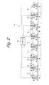
Claims (5)

  1. A suspension control system comprising:
    a coupling portion configured to couple at least two vehicle bodies and connect a first vehicle body and a second vehicle body adjacent to each other in such a manner that a driving force can be transmitted therebetween;
    a coupling bogie configured to provide a support on at least a second vehicle body side of the first vehicle body via a spring member;
    a cylinder apparatus disposed between the coupling bogie and the first vehicle body and configured to exert an application force adjustable by an actuator;
    a controller configured to control the actuator;
    a first vibration detector configured to detect a vibration of the first vehicle body; and
    a second vibration detector configured to detect a vibration of the second vehicle body,
    wherein the controller calculates an instruction value for the actuator based on a detection value of the first vibration detector and a detection value of the second vibration detector.
  2. The suspension control system according to claim 1, wherein a single vehicle body or a plurality of vehicle bodies is further additionally coupled to the first vehicle body and/or the second vehicle body, and
    wherein the controller calculates the instruction value for the actuator without using a vibration of at least one vehicle body located away from the coupling portion among the added vehicle bodies.
  3. The suspension control system according to claim 1 or 2, further comprising a second cylinder apparatus disposed between the coupling bogie and the second vehicle body and configured to exert an application force adjustable by a second actuator,
    wherein the controller calculates an instruction value for the second actuator based on the detection value of the first vibration detector and the detection value of the second vibration detector.
  4. The suspension control system according to any of claims 1 to 3, wherein the controller includes a high-pass filter configured to remove a component of a lower frequency than a resonance frequency of bouncing and pitching of the first and second vehicle bodies from the detection value of the first vibration detector and the detection value of the second vibration detector.
  5. The suspension control system according to any of claims 1 to 4, further comprising an inter-vehicle displacement sensor configured to detect an inter-vehicle displacement between the first vehicle body and the second vehicle body,
    wherein the second vibration detector calculates the vibration of the second vehicle body based on the detection value of the first vibration detector and a detection value of the inter-vehicle displacement sensor.
EP14173863.3A 2013-06-28 2014-06-25 Suspension control system Withdrawn EP2848490A1 (en)

Applications Claiming Priority (1)

Application Number Priority Date Filing Date Title
JP2013137265A JP2015009696A (en) 2013-06-28 2013-06-28 Suspension control device

Publications (1)

Publication Number Publication Date
EP2848490A1 true EP2848490A1 (en) 2015-03-18

Family

ID=50982809

Family Applications (1)

Application Number Title Priority Date Filing Date
EP14173863.3A Withdrawn EP2848490A1 (en) 2013-06-28 2014-06-25 Suspension control system

Country Status (3)

Country Link
EP (1) EP2848490A1 (en)
JP (1) JP2015009696A (en)
CN (1) CN104249743A (en)

Cited By (2)

* Cited by examiner, † Cited by third party
Publication number Priority date Publication date Assignee Title
EP3587167A4 (en) * 2017-02-22 2021-01-13 Hitachi Automotive Systems, Ltd. ACTUATOR DEVICE
FR3145736A1 (en) * 2023-02-13 2024-08-16 Alstom Holdings Railway vehicle with anti-roll systems on the middle bogie connected only to the load-bearing end of at least some cars

Families Citing this family (10)

* Cited by examiner, † Cited by third party
Publication number Priority date Publication date Assignee Title
JP6474112B2 (en) * 2015-01-30 2019-02-27 日立オートモティブシステムズ株式会社 Vehicle vibration control device
JP6606025B2 (en) * 2016-06-28 2019-11-13 本田技研工業株式会社 Driving skill determination device
JP6364100B1 (en) * 2017-01-30 2018-07-25 Kyb株式会社 Steady acceleration detection device and railcar vibration damping device
AT520200B1 (en) * 2017-07-18 2019-02-15 Siemens Ag Oesterreich Device and method for determining the load for vehicles
CN107539332B (en) * 2017-07-25 2019-08-20 西南交通大学 High-speed train lateral semi-active suspension control system and control method based on resonance control
JP6939540B2 (en) * 2017-12-28 2021-09-22 日本製鉄株式会社 Contact angle estimation system, contact angle estimation method, and program
CN110155103B (en) * 2019-05-27 2020-10-23 西南交通大学 A semi-active suspension control system and method for high-speed trains based on LQG control
CN112506043B (en) * 2020-11-11 2022-10-11 中车青岛四方机车车辆股份有限公司 Control method and control system for rail vehicle and vertical shock absorber
CN112678010B (en) * 2021-01-12 2022-03-01 中车青岛四方机车车辆股份有限公司 Rail vehicle and control method and system thereof
CN117719554B (en) * 2024-02-18 2024-04-26 成都磁速科技有限公司 High-temperature superconductive magnetic levitation track inspection early warning system

Citations (8)

* Cited by examiner, † Cited by third party
Publication number Priority date Publication date Assignee Title
DE960899C (en) * 1954-05-29 1957-03-28 Linke Hofmann Busch Stabilizing device for rail link units or links
DE1010094B (en) * 1955-06-04 1957-06-13 Franz Kruckenberg Dipl Ing Suspension of the car body (s) of a rail vehicle on a (single or multi-axle) running gear by means of air springs
FR2593455A1 (en) * 1986-01-29 1987-07-31 Hitachi Ltd DEVICE FOR CONTROLLING VIBRATIONS FOR VEHICLES.
DE4311521C1 (en) * 1993-04-07 1994-04-21 Talbot Waggonfab Support against unsteadiness in rail vehicle - has cross inclination control with length-alterable, adjustable connecting piece controlled by drive component
US5560589A (en) * 1995-07-12 1996-10-01 Northrop Grumman Corporation Active vibration damping arrangement for transportation vehicles
DE102007008444A1 (en) * 2007-02-19 2008-08-28 Bombardier Transportation Gmbh Vehicle with a roll support
DE102008060640A1 (en) * 2008-12-05 2010-06-17 Zf Friedrichshafen Ag Piston cylinder aggregates e.g. monotube vibration damper, arrangement for pivot mounting of rail-mounted vehicle, has piston cylinder aggregates supporting superstructures such that pressure-free exchange of damping medium takes place
JP2012076553A (en) 2010-09-30 2012-04-19 Hitachi Automotive Systems Ltd Vibration control device for railroad vehicle

Patent Citations (8)

* Cited by examiner, † Cited by third party
Publication number Priority date Publication date Assignee Title
DE960899C (en) * 1954-05-29 1957-03-28 Linke Hofmann Busch Stabilizing device for rail link units or links
DE1010094B (en) * 1955-06-04 1957-06-13 Franz Kruckenberg Dipl Ing Suspension of the car body (s) of a rail vehicle on a (single or multi-axle) running gear by means of air springs
FR2593455A1 (en) * 1986-01-29 1987-07-31 Hitachi Ltd DEVICE FOR CONTROLLING VIBRATIONS FOR VEHICLES.
DE4311521C1 (en) * 1993-04-07 1994-04-21 Talbot Waggonfab Support against unsteadiness in rail vehicle - has cross inclination control with length-alterable, adjustable connecting piece controlled by drive component
US5560589A (en) * 1995-07-12 1996-10-01 Northrop Grumman Corporation Active vibration damping arrangement for transportation vehicles
DE102007008444A1 (en) * 2007-02-19 2008-08-28 Bombardier Transportation Gmbh Vehicle with a roll support
DE102008060640A1 (en) * 2008-12-05 2010-06-17 Zf Friedrichshafen Ag Piston cylinder aggregates e.g. monotube vibration damper, arrangement for pivot mounting of rail-mounted vehicle, has piston cylinder aggregates supporting superstructures such that pressure-free exchange of damping medium takes place
JP2012076553A (en) 2010-09-30 2012-04-19 Hitachi Automotive Systems Ltd Vibration control device for railroad vehicle

Cited By (3)

* Cited by examiner, † Cited by third party
Publication number Priority date Publication date Assignee Title
EP3587167A4 (en) * 2017-02-22 2021-01-13 Hitachi Automotive Systems, Ltd. ACTUATOR DEVICE
FR3145736A1 (en) * 2023-02-13 2024-08-16 Alstom Holdings Railway vehicle with anti-roll systems on the middle bogie connected only to the load-bearing end of at least some cars
EP4417483A1 (en) * 2023-02-13 2024-08-21 ALSTOM Holdings Railway vehicle comprising anti-roll systems on a median bogie connected only to the bearing end of at least certain cars

Also Published As

Publication number Publication date
JP2015009696A (en) 2015-01-19
CN104249743A (en) 2014-12-31

Similar Documents

Publication Publication Date Title
JP2015009696A (en) Suspension control device
CN111247351B (en) Dynamic motion control system using magnetorheological fluid clutch apparatus
CN1704862B (en) Adaptive automobile running control system and method
CN101474953B (en) Suspension control apparatus
CN113635931B (en) Vehicle body posture adjusting method and vehicle body posture adjusting system
Katsuyama et al. Improvement of ride comfort by unsprung negative skyhook damper control using in-wheel motors
AU2017325182A1 (en) Vehicle for travelling along a linear route guideway
JP7204041B2 (en) Operating state diagnosis device
JP4191013B2 (en) Damping device and vehicle with damping function
CN101835644A (en) Method and system for influencing the movement of a motor vehicle body, the chain of movements of which can be controlled or adjusted, and associated vehicle
JP5675405B2 (en) Track-based transportation vehicle and vehicle body posture control device
JP2019031145A (en) Vibration suppressing system for railway vehicle and method for the same
AU2003273830B2 (en) Running gear comprising an inclining system for rail vehicles
JP5643124B2 (en) Inter-vehicle damper device
CN107207017A (en) vehicle shock absorber
JP4700862B2 (en) Railway vehicle
JP4429955B2 (en) Vehicle vibration control device
FI130684B1 (en) Motorized underframe for rail vehicles
Pavlov et al. Influence of the braking on the comfort during positioning of a metro train
CN115384254B (en) An adaptive suspension system and its application
JP6862938B2 (en) Yaw damper device for railway vehicles
JP6557407B2 (en) Railway vehicle
Enomoto et al. Development of tilt control system using electro-hydraulic actuators
Sughara et al. Suppression of vertical vibrations in railway vehicles using variable primary and secondary hydraulic dampers
US5608630A (en) Universal dynamic stabilizer

Legal Events

Date Code Title Description
PUAI Public reference made under article 153(3) epc to a published international application that has entered the european phase

Free format text: ORIGINAL CODE: 0009012

17P Request for examination filed

Effective date: 20140625

AK Designated contracting states

Kind code of ref document: A1

Designated state(s): AL AT BE BG CH CY CZ DE DK EE ES FI FR GB GR HR HU IE IS IT LI LT LU LV MC MK MT NL NO PL PT RO RS SE SI SK SM TR

AX Request for extension of the european patent

Extension state: BA ME

STAA Information on the status of an ep patent application or granted ep patent

Free format text: STATUS: THE APPLICATION IS DEEMED TO BE WITHDRAWN

18D Application deemed to be withdrawn

Effective date: 20150919