EP2848474A1 - Vehicular exterior member - Google Patents
Vehicular exterior member Download PDFInfo
- Publication number
- EP2848474A1 EP2848474A1 EP14178222.7A EP14178222A EP2848474A1 EP 2848474 A1 EP2848474 A1 EP 2848474A1 EP 14178222 A EP14178222 A EP 14178222A EP 2848474 A1 EP2848474 A1 EP 2848474A1
- Authority
- EP
- European Patent Office
- Prior art keywords
- exterior member
- area
- layer
- designed
- transparent
- Prior art date
- Legal status (The legal status is an assumption and is not a legal conclusion. Google has not performed a legal analysis and makes no representation as to the accuracy of the status listed.)
- Withdrawn
Links
- 239000010410 layer Substances 0.000 claims abstract description 115
- 239000000463 material Substances 0.000 claims abstract description 50
- 239000011347 resin Substances 0.000 claims abstract description 39
- 229920005989 resin Polymers 0.000 claims abstract description 39
- 239000012790 adhesive layer Substances 0.000 claims abstract description 13
- 239000000853 adhesive Substances 0.000 claims description 13
- 230000001070 adhesive effect Effects 0.000 claims description 13
- 230000005540 biological transmission Effects 0.000 claims description 12
- 230000002708 enhancing effect Effects 0.000 abstract description 5
- 238000000034 method Methods 0.000 description 10
- 239000004417 polycarbonate Substances 0.000 description 7
- 229920000515 polycarbonate Polymers 0.000 description 7
- 238000000576 coating method Methods 0.000 description 6
- 229920003229 poly(methyl methacrylate) Polymers 0.000 description 6
- 239000004926 polymethyl methacrylate Substances 0.000 description 6
- 229920001923 acrylonitrile-ethylene-styrene Polymers 0.000 description 5
- 239000011248 coating agent Substances 0.000 description 5
- 238000007740 vapor deposition Methods 0.000 description 5
- 239000002184 metal Substances 0.000 description 4
- 229910052751 metal Inorganic materials 0.000 description 4
- 239000003973 paint Substances 0.000 description 4
- 238000004519 manufacturing process Methods 0.000 description 3
- 238000000465 moulding Methods 0.000 description 3
- 239000005020 polyethylene terephthalate Substances 0.000 description 3
- 229920000139 polyethylene terephthalate Polymers 0.000 description 3
- 239000004793 Polystyrene Substances 0.000 description 2
- NIXOWILDQLNWCW-UHFFFAOYSA-N acrylic acid group Chemical group C(C=C)(=O)O NIXOWILDQLNWCW-UHFFFAOYSA-N 0.000 description 2
- 230000015572 biosynthetic process Effects 0.000 description 2
- 230000000295 complement effect Effects 0.000 description 2
- 235000021189 garnishes Nutrition 0.000 description 2
- 229910052738 indium Inorganic materials 0.000 description 2
- APFVFJFRJDLVQX-UHFFFAOYSA-N indium atom Chemical compound [In] APFVFJFRJDLVQX-UHFFFAOYSA-N 0.000 description 2
- 238000007747 plating Methods 0.000 description 2
- 230000003014 reinforcing effect Effects 0.000 description 2
- JOYRKODLDBILNP-UHFFFAOYSA-N Ethyl urethane Chemical compound CCOC(N)=O JOYRKODLDBILNP-UHFFFAOYSA-N 0.000 description 1
- 239000004676 acrylonitrile butadiene styrene Substances 0.000 description 1
- 230000003044 adaptive effect Effects 0.000 description 1
- 230000015556 catabolic process Effects 0.000 description 1
- 239000003086 colorant Substances 0.000 description 1
- 230000007797 corrosion Effects 0.000 description 1
- 238000005260 corrosion Methods 0.000 description 1
- 238000006731 degradation reaction Methods 0.000 description 1
- 230000000994 depressogenic effect Effects 0.000 description 1
- 239000000428 dust Substances 0.000 description 1
- 230000000694 effects Effects 0.000 description 1
- 238000005516 engineering process Methods 0.000 description 1
- PNWJXICONNROSM-UHFFFAOYSA-N ethene;prop-2-enenitrile;styrene Chemical compound C=C.C=CC#N.C=CC1=CC=CC=C1 PNWJXICONNROSM-UHFFFAOYSA-N 0.000 description 1
- 238000007429 general method Methods 0.000 description 1
- PCHJSUWPFVWCPO-UHFFFAOYSA-N gold Chemical compound [Au] PCHJSUWPFVWCPO-UHFFFAOYSA-N 0.000 description 1
- 229910052737 gold Inorganic materials 0.000 description 1
- 239000010931 gold Substances 0.000 description 1
- 230000008595 infiltration Effects 0.000 description 1
- 238000001764 infiltration Methods 0.000 description 1
- 230000008018 melting Effects 0.000 description 1
- 238000002844 melting Methods 0.000 description 1
- 239000007769 metal material Substances 0.000 description 1
- 150000002739 metals Chemical class 0.000 description 1
- -1 polyethylene terephthalate Polymers 0.000 description 1
- 229920002223 polystyrene Polymers 0.000 description 1
- 238000003466 welding Methods 0.000 description 1
Images



Classifications
-
- B—PERFORMING OPERATIONS; TRANSPORTING
- B60—VEHICLES IN GENERAL
- B60R—VEHICLES, VEHICLE FITTINGS, OR VEHICLE PARTS, NOT OTHERWISE PROVIDED FOR
- B60R13/00—Elements for body-finishing, identifying, or decorating; Arrangements or adaptations for advertising purposes
- B60R13/005—Manufacturers' emblems, name plates, bonnet ornaments, mascots or the like; Mounting means therefor
-
- B—PERFORMING OPERATIONS; TRANSPORTING
- B60—VEHICLES IN GENERAL
- B60R—VEHICLES, VEHICLE FITTINGS, OR VEHICLE PARTS, NOT OTHERWISE PROVIDED FOR
- B60R13/00—Elements for body-finishing, identifying, or decorating; Arrangements or adaptations for advertising purposes
- B60R13/04—External Ornamental or guard strips; Ornamental inscriptive devices thereon
-
- B—PERFORMING OPERATIONS; TRANSPORTING
- B60—VEHICLES IN GENERAL
- B60R—VEHICLES, VEHICLE FITTINGS, OR VEHICLE PARTS, NOT OTHERWISE PROVIDED FOR
- B60R19/00—Wheel guards; Radiator guards, e.g. grilles; Obstruction removers; Fittings damping bouncing force in collisions
- B60R19/02—Bumpers, i.e. impact receiving or absorbing members for protecting vehicles or fending off blows from other vehicles or objects
- B60R19/48—Bumpers, i.e. impact receiving or absorbing members for protecting vehicles or fending off blows from other vehicles or objects combined with, or convertible into, other devices or objects, e.g. bumpers combined with road brushes, bumpers convertible into beds
- B60R19/483—Bumpers, i.e. impact receiving or absorbing members for protecting vehicles or fending off blows from other vehicles or objects combined with, or convertible into, other devices or objects, e.g. bumpers combined with road brushes, bumpers convertible into beds with obstacle sensors of electric or electronic type
-
- B—PERFORMING OPERATIONS; TRANSPORTING
- B60—VEHICLES IN GENERAL
- B60R—VEHICLES, VEHICLE FITTINGS, OR VEHICLE PARTS, NOT OTHERWISE PROVIDED FOR
- B60R21/00—Arrangements or fittings on vehicles for protecting or preventing injuries to occupants or pedestrians in case of accidents or other traffic risks
- B60R21/01—Electrical circuits for triggering passive safety arrangements, e.g. airbags, safety belt tighteners, in case of vehicle accidents or impending vehicle accidents
- B60R21/013—Electrical circuits for triggering passive safety arrangements, e.g. airbags, safety belt tighteners, in case of vehicle accidents or impending vehicle accidents including means for detecting collisions, impending collisions or roll-over
- B60R21/0134—Electrical circuits for triggering passive safety arrangements, e.g. airbags, safety belt tighteners, in case of vehicle accidents or impending vehicle accidents including means for detecting collisions, impending collisions or roll-over responsive to imminent contact with an obstacle, e.g. using radar systems
-
- G—PHYSICS
- G01—MEASURING; TESTING
- G01S—RADIO DIRECTION-FINDING; RADIO NAVIGATION; DETERMINING DISTANCE OR VELOCITY BY USE OF RADIO WAVES; LOCATING OR PRESENCE-DETECTING BY USE OF THE REFLECTION OR RERADIATION OF RADIO WAVES; ANALOGOUS ARRANGEMENTS USING OTHER WAVES
- G01S7/00—Details of systems according to groups G01S13/00, G01S15/00, G01S17/00
- G01S7/02—Details of systems according to groups G01S13/00, G01S15/00, G01S17/00 of systems according to group G01S13/00
- G01S7/03—Details of HF subsystems specially adapted therefor, e.g. common to transmitter and receiver
-
- G—PHYSICS
- G01—MEASURING; TESTING
- G01S—RADIO DIRECTION-FINDING; RADIO NAVIGATION; DETERMINING DISTANCE OR VELOCITY BY USE OF RADIO WAVES; LOCATING OR PRESENCE-DETECTING BY USE OF THE REFLECTION OR RERADIATION OF RADIO WAVES; ANALOGOUS ARRANGEMENTS USING OTHER WAVES
- G01S13/00—Systems using the reflection or reradiation of radio waves, e.g. radar systems; Analogous systems using reflection or reradiation of waves whose nature or wavelength is irrelevant or unspecified
- G01S13/88—Radar or analogous systems specially adapted for specific applications
- G01S13/93—Radar or analogous systems specially adapted for specific applications for anti-collision purposes
- G01S13/931—Radar or analogous systems specially adapted for specific applications for anti-collision purposes of land vehicles
- G01S2013/9323—Alternative operation using light waves
-
- G—PHYSICS
- G01—MEASURING; TESTING
- G01S—RADIO DIRECTION-FINDING; RADIO NAVIGATION; DETERMINING DISTANCE OR VELOCITY BY USE OF RADIO WAVES; LOCATING OR PRESENCE-DETECTING BY USE OF THE REFLECTION OR RERADIATION OF RADIO WAVES; ANALOGOUS ARRANGEMENTS USING OTHER WAVES
- G01S13/00—Systems using the reflection or reradiation of radio waves, e.g. radar systems; Analogous systems using reflection or reradiation of waves whose nature or wavelength is irrelevant or unspecified
- G01S13/88—Radar or analogous systems specially adapted for specific applications
- G01S13/93—Radar or analogous systems specially adapted for specific applications for anti-collision purposes
- G01S13/931—Radar or analogous systems specially adapted for specific applications for anti-collision purposes of land vehicles
- G01S2013/9327—Sensor installation details
- G01S2013/93271—Sensor installation details in the front of the vehicles
-
- G—PHYSICS
- G01—MEASURING; TESTING
- G01S—RADIO DIRECTION-FINDING; RADIO NAVIGATION; DETERMINING DISTANCE OR VELOCITY BY USE OF RADIO WAVES; LOCATING OR PRESENCE-DETECTING BY USE OF THE REFLECTION OR RERADIATION OF RADIO WAVES; ANALOGOUS ARRANGEMENTS USING OTHER WAVES
- G01S7/00—Details of systems according to groups G01S13/00, G01S15/00, G01S17/00
- G01S7/02—Details of systems according to groups G01S13/00, G01S15/00, G01S17/00 of systems according to group G01S13/00
- G01S7/03—Details of HF subsystems specially adapted therefor, e.g. common to transmitter and receiver
- G01S7/032—Constructional details for solid-state radar subsystems
Definitions
- the present invention relates to an exterior member disposed in a vehicle.
- vehicular exterior members represented by a front grille, a back door garnish, and the like
- various members have been hitherto known.
- vehicular exterior members there is a member in which various types of designed bodies are integrated into a base body (called an exterior body).
- an exterior body As the designed body, for example, there is an emblem.
- the designed body has a decorative layer which displays a predetermined design.
- the decorative layer is composed of metal, paint, a resin material, or the like and displays the design using color differences and uneven shapes.
- the decorative layer is generally covered with a transparent layer made of a transparent resin material.
- the design of the decorative layer is displayed to the outside through the transparent layer.
- the decorative layer covered with the transparent layer is less likely to be directly exposed to sunlight, rainwater, or the like and is thus less likely to deteriorate. That is, the transparent layer contributes to the weather resistance of the designed body.
- the exterior body is an exterior member of a vehicle and is thus colored, and the designed body is fixed to the surface side of the exterior body while the transparent layer faces the surface side.
- the designed body is fixed to the surface of the exterior body. Therefore, the boundary portion between the designed body and the exterior body is still exposed to the outside. Accordingly, there is a possibility that rainwater or the like that infiltrates into the rear side of the designed body from the boundary portion may reach the decorative layer.
- a technique is suggested in which at least a portion of an exterior body is composed of a transparent resin material and a decorative layer is directly formed on the rear surface side of the transparent exterior body (for example, refer to JP 2012-112660 A ).
- a decorative layer is directly formed on the rear surface side of the transparent exterior body.
- the decorative layer is less likely to be exposed to the outside.
- the entire exterior body which is a relatively large member needs to be handled during the formation of the decorative layer, resulting in the degradation in workability.
- the entire exterior body needs to be put in a vacuum chamber for the vapor deposition method, and thus a very large vacuum chamber is needed to manufacture a single vehicular exterior member. Therefore, it takes a long time to manufacture the single vehicular exterior member. That is, this type of existing vehicular exterior member has a problem in that it is difficult to allow weather resistance and productivity to be compatible with each other.
- the present invention provides a vehicular exterior member having excellent productivity while enhancing weather resistance.
- a vehicular exterior member of the present invention includes: an exterior body which is made of a transparent resin material; and a designed body which is smaller than the exterior body in size and is integrated into the exterior body, wherein the exterior body includes a display portion so that the designed body is fixed to a rear surface side of the display portion, a concave portion is provided on the rear surface side of the display portion, the designed body includes a transparent layer made of a transparent resin material and a decorative layer provided on a rear surface side of the transparent layer, the designed body is disposed inside the concave portion while the transparent layer faces the exterior body side, and an adhesive layer made of a transparent adhesive material is interposed between the transparent layer of the designed body and the exterior body.
- the vehicular exterior member of the present invention may be provided with any one of (1) to (4) as below or may be provided with a plurality thereof.
- the concave portion is provided on the rear surface side of the transparent exterior body, and the designed body is disposed inside the concave portion. Since the designed body is disposed on the rear surface side of the exterior body, the designed body is less likely to be exposed to the outside, and thus the designability and/or the functionality thereof is less likely to deteriorate. In addition, since the designed body provided with the decorative layer is smaller than the exterior body in size, productivity is also enhanced. Therefore, according to the vehicular exterior member of the present invention, weather resistance and productivity are compatible with each other.
- the same designed body can be shared by exterior bodies having various shapes, and thus there is an advantage that productivity is further enhanced.
- the decorative layer of the designed body and the external environment are separated from each other by the transparent exterior body, the transparent adhesive layer, and the transparent layer of the designed body. That is, the decorative layer of the designed body is displayed to the outside through the transparent thick layer (the exterior body, the adhesive layer, and the transparent layer). Therefore, according to the vehicular exterior member of the present invention, a distinctive design having a sense of depth can be displayed.
- a transparent resin material forming an exterior body and a transparent resin material forming a designed body may be the same or may be different from each other.
- the transparent resin materials thereof may have the same degree of transparency, and the exterior body and the transparent layer may be formed of the same type of transparent resin material.
- At least one type selected from polymethylmethacrylate resin (PMMA), polycarbonate (PC), polystyrene (PS), and polyethylene terephthalate (PET) may be selected.
- a transparent adhesive material may be a material that can adhere to the exterior body and the transparent layer and is transparent, and the type thereof is not particularly limited.
- the transparent adhesive material at least one type selected from various types of urethane based adhesives and various types of acrylic based adhesives may be exemplified.
- the thickness of the adhesive layer formed from the transparent adhesive material is not particularly limited but may be generally 100 ⁇ m to 500 ⁇ m, and is smaller than those of the exterior body and the transparent layer.
- the designed body may simply display a design similarly to the emblem described above. Otherwise, the designed body may have a certain function such as a radio wave transmission cover, which will be described later.
- the designed body composes a portion of the vehicular exterior member and thus may have excellent weather resistance.
- a liner layer may be transparent or may be colored.
- the liner layer may cover not only the rear surface side of the designed body but also the rear surface side of the exterior body. That is, the rear surface side of the designed body of the present invention in which the designed body is adhered to the exterior body may further be covered with a single liner layer.
- the liner layer may be molded separately from the vehicular exterior member and be integrated through methods such as adhesion, welding, or fitting. Otherwise, the liner layer may be molded integrally with the vehicular exterior member through an insert resin molding method or the like.
- a second liner layer may be provided in advance on the rear surface side of the decorative layer in the designed body.
- the second liner layer may be made of the same type of resin material as the liner layer described above, or may be made of a resin material having a higher melting point than that of the liner layer described above so as to protect the decorative layer with high reliability during the resin molding.
- At least a portion of the designed body and/or at least a portion of the exterior body may be made of only a transparent resin material.
- a function as a lens portion in a luminous ornament may be imparted to a transparent designed body and a transparent exterior body.
- the luminous ornament is a device that includes a luminous body (for example, an LED light) as a light source and the lens portion which transmits light emitted by the luminous body, and allows a design corresponding to the shape of the lens portion to glow so as to be displayed.
- the corresponding design to the three-dimensional shape of the designed body and/or the exterior body may be allowed to glow so as to be displayed.
- the designed body and the decorative layer need to be formed of a transparent resin material.
- the decorative layer needs to be provided with a predetermined uneven surface for allowing the design to glow so as to be displayed.
- the uneven surface needs to be adjacent to a second decorative layer made of a material having a different refractive index from that of the decorative layer.
- the second decorative layer may be, for example, an air layer.
- an uneven surface that is complementary to the uneven surface of the decorative layer may be provided in the transparent layer so as to use the transparent layer as the second decorative layer.
- the materials of the designed body and the exterior body may use at least one type selected from PMMA, PC, PS, and PET.
- the radio wave transmission cover is one of members for adaptive cruise control (ACC).
- the ACC is a technique of measuring the distance and relative speed between a vehicle and a vehicle in front using a sensor mounted in the front of the vehicle and controlling the throttles and brakes on the basis of the information to accelerate or decelerate the vehicle, thereby controlling the distance between the vehicles.
- the ACC has received attention as one of core technologies of the intelligent transportation system (ITS) which is aimed at reducing traffic congestion and accidents.
- ITS intelligent transportation system
- a laser radar or a millimeter wave radar is generally used as the sensor of the ACC.
- a millimeter wave is a radio wave having a frequency of 30 GHz to 300 GHz and a wavelength of 1 to 10 mm.
- the millimeter wave radar transmits a millimeter wave and receives the millimeter wave reflected from an object.
- the distance or relative speed between the vehicle and the vehicle in front is measured from the difference between the transmitted wave and the received wave.
- a vehicular radio wave radar device is generally disposed in the rear of an exterior member represented by a front grille. Therefore, in this case, a part of the front grille which is located in the front of the vehicular radio wave radar device needs to be composed of a cover (radio wave transmission cover) that can transmit radio waves. This is because a general front grille is subjected to uneven shapes or metal plating for the purpose of displaying a three-dimensional design.
- the material may include a resin material, various types of paint, and metals (for example, indium and gold) deposited in island shapes.
- the transparent layer that composes the designed body may be made of a resin material having a low dielectric loss tangent.
- the dielectric loss tangent is small, radio waves such as millimeter waves are less likely to be converted into thermal energy, and thus attenuation in radio waves can be suppressed.
- the second liner layer described above is provided in the designed body
- the second liner layer as well as the transparent layer may be made of a material having a low dielectric loss tangent.
- the transparent resin material and the transparent adhesive material forming the exterior body may also be made of a material having a low dielectric loss tangent.
- a transparent resin material having a low dielectric loss tangent PMMA and PC are exemplified.
- a transparent adhesive material having a low dielectric loss tangent acrylic based adhesives are exemplified.
- a colored resin material having a low dielectric loss tangent acrylonitrile ethylene styrene (AES), acrylonitrile butadiene styrene (ABS), and PC are exemplified.
- the colored resin material having a low dielectric loss tangent may be used for the liner layer, the second liner layer, and the like.
- the relative permittivities of at least the transparent resin material forming the exterior body, the transparent resin material forming the designed body, and the transparent adhesive material may be substantially the same. Specifically, the relative permittivities thereof may be 2.7 ⁇ 1.5 at 76.5 GHz and at room temperature.
- the resin material forming the liner layer a material having a permittivity in the above range may be used.
- the thickness of the designed body may be constant. This is because the overall thickness of the vehicular exterior member is easily controlled as described later.
- the constant thickness of the designed body mentioned here is a concept that includes a substantially constant thickness. Specifically, when the maximum thickness of the designed body is 100%, variations of -5% are permitted.
- the vehicular exterior member of an embodiment is a front grille for a vehicle and includes a millimeter wave transmission cover as the designed body.
- FIG. 1 is a perspective view schematically illustrating the vehicle in which the vehicular exterior member of the embodiment is disposed.
- FIG. 2 is a front view schematically illustrating the vehicular exterior member of the embodiment.
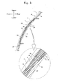
- FIG. 3 is a cross-sectional view schematically illustrating a state in which the vehicular exterior member of the embodiment is cut in the thickness direction and the vertical direction.
- FIG. 4 is an explanatory view illustrating a "crossing angle" in the vehicular exterior member of the embodiment.
- upper, lower, left, right, front, and rear represent upper, lower, left, right, front, and rear illustrated in FIGS. 1 to 3 .
- the vertical direction in this embodiment represents the upper/lower direction (in other words, vertical direction) illustrated in FIGS. 1 to 4 .
- the rear surface side represents the rear side in FIG. 1
- the surface side represents the front side in FIG. 1
- the front side represents the forward side in a vehicle traveling direction
- the rear side represents the backward side in the vehicle traveling direction.
- a vehicular exterior member of the embodiment includes an exterior body 2 and a designed body 3.
- the vehicular exterior member 1 of the embodiment further includes a general decorative portion 8.
- the exterior body 2 composes the base body in the front grille of a vehicle 100.
- the designed body 3 composes an emblem and is fixed to the upper portion of the exterior body 2.
- the exterior body 2 is made of PMMA which is a type of transparent resin.
- a concave portion 20 is provided in the upper portion of the rear surface side of the exterior body 2.
- the concave portion 20 has a depressed shape which is substantially complementary to the shape of the designed body 3.
- An area in the exterior body 2 where the concave portion 20 is provided is referred to as a display portion 28, and the other area therein is referred to as a general portion 29.
- the thickness of the display portion 28 is smaller than that of the general portion 29 by the depth of the concave portion 20.
- the general portion 29 has a net shape with a large number of through-holes 29a.
- the general decorative portion 8 which is formed by coating is integrated into the rear surface side of the general portion 29.
- various methods such as vapor deposition, plating, and two-color molding may be selected.
- coating since the front grille is a relatively large member, coating may be selected in consideration of the ease of formation of the general decorative portion 8.
- the rear surface side of the general decorative portion 8 may be covered with a reinforcing layer in order to prevent corrosion and the like.
- the reinforcing layer may be formed by a general method such as coating.
- the paint may be colored, and various colors such as black, metallic color, and mirror coating may be exemplified.
- the general decorative portion 8 exhibits a metallic color and the general portion 29 is transparent, when the general portion 29 is viewed from the front, a design with the metallic color of the general decorative portion 8 is recognized through the general portion 29.
- the general portion 29 is made of the transparent resin material, a distinctive design in which a metallic material is disposed on the inside of the transparent layer is displayed on the general portion 29.
- the general decorative portion 8 is integrated into only the rear surface side of the general portion 29 but may also be further integrated into the rear surface side of the concave portion 20 (specifically, the further rear surface side of the designed body 3 which will be described later) depending on the cases.
- the general decorative portion 8 is integrated into the exterior body 2.
- the general decorative portion 8 may not be provided in the vehicular exterior member 1 of the present invention.
- the designed body 3 includes a transparent layer 30, a decorative layer 31, and a liner layer 32.
- the transparent layer 30 is made of polycarbonate which is a type of transparent resin.
- the rear surface of the transparent layer 30 is an uneven surface. A part of the uneven surface which is recessed when viewed from the rear surface side of the transparent layer 30 is referred to as a designed concave surface 38 and a part thereof which protrudes is referred to as a designed convex surface 39.
- the decorative layer 31 includes a bright layer 35 made of indium and a colored layer 36 made of a colored paint.
- the colored layer 36 is formed by a coating method and is formed on the designed convex surface 39 of the transparent layer 30.
- the bright layer 35 is formed through a vapor deposition method and is formed on the designed concave surface 38 and the rear surfaces of the colored layer 36 of the transparent layer 30. In other words, the bright layer 35 is deposited on the entire rear surface side of the transparent layer 30 which has the colored layer 36.
- the liner layer 32 is made of an AES resin and is formed integrally with the rear surface side of the bright layer 35. Note that the relative permittivity of the AES resin is substantially the same as that of polycarbonate. Further, the dielectric loss tangent of the AES resin is 0.007, and the dielectric loss tangent of polycarbonate is 0.006. These values are sufficiently low values, and thus the designed body 3 in the vehicular exterior member 1 of the embodiment can be used as a radio wave (more specifically, millimeter wave) transmission cover.
- the thickness of the designed body 3 is substantially constant. Specifically, the thickness of the designed body 3 is in a range of 8.4 mm ⁇ 0.3 mm.
- the designed body 3 is disposed inside the concave portion 20 while the transparent layer 30 faces the front direction.
- the designed body 3 is disposed inside the concave portion 20 while the transparent layer 30 faces the rear surface of the concave portion 20 in the exterior body 2.
- the designed body 3 and the exterior body 2 are integrated into each other by the transparent adhesive material. Therefore, an adhesive layer 4 is interposed between the designed body 3 and the exterior body 2.
- PMMA is used as the transparent adhesive material.
- the adhesive layer 4 comes into contact with the bottom surface (that is, the rear surface) and the side surface of the concave portion 20 and comes into contact with the front surface (that is, the front surface of the transparent layer 30) and the entire side surface of the designed body 3. Therefore, the designed body 3 is firmly integrated into the exterior body 2.
- a part where the vehicular exterior member 1 is attached has two areas having different inclination angles.
- the area having a larger inclination angle is an area A to which the upper portion of the vehicular exterior member 1 is attached.
- the area having a smaller inclination angle is an area B to which the lower portion of the vehicular exterior member 1 is attached. Since the vehicular exterior member 1 of the embodiment is a member which is attached to the two areas (the areas A and B), in order to cope with the two areas, the vehicular exterior member 1 has two areas (a first area 50 and a second area 60) having different inclination angles.
- the vehicular exterior member 1 has the two areas (the first area 50 and the second area 60) arranged in the upper/lower direction ( FIG. 4 ).
- the first area 50 composes the upper part of the vehicular exterior member 1 in the vertical direction.
- the second area 60 composes the lower part of the vehicular exterior member 1 in the vertical direction.
- the first area 50 is located on the upper side in relation to the second area 60. Further, in the state where the vehicular exterior member 1 is attached to the vehicle 100, an inclination angle ⁇ 1 of the first area 50 is about 45°, and an inclination angle ⁇ 2 of the second area 60 is about 15°.
- the inclination angles ( ⁇ 1 and ⁇ 2) of the vehicular exterior member 1 mentioned here indicate angles (minor angles) between a tangent line L1 and a vertical line L0 illustrated in FIG. 4 .
- the tangent line L1 is a tangent line drawn on a cross-section of the vehicular exterior member 1 cut in the vertical direction and the thickness direction.
- the inclination angle ⁇ 1 is equal to or greater than 30° and equal to or smaller than 90°.
- the inclination angle ⁇ 2 is equal to or greater than 0° and smaller than 30°.
- the first area 50 in the vehicular exterior member 1 of the embodiment is an area which is located on the upper side in the vertical direction as described above and is an area in which the crossing angle with respect to the vertical direction when the vehicular exterior member 1 is attached to the vehicle 100 is equal to or greater than 30° and equal to or smaller than 90°.
- the second area 60 is an area which is located on the lower side in the vertical direction and is an area in which the crossing angle with respect to the vertical direction when the vehicular exterior member 1 is attached to the vehicle 100 is equal to or greater than 0° and smaller than 30°.
- the concave portion 20 is provided over a portion of the first area 50 and a portion of the second area 60.
- the inclination angles of the first and second areas 50 and 60 are not limited thereto.
- the first and second areas 50 and 60 do not necessarily need to be adjacent to each other.
- a radio wave radar (not illustrated) is disposed in the rear of the designed body 3 in the vehicular exterior member 1.
- the thickness of the vehicular exterior member 1 in a radio wave outgoing path and the thickness of the vehicular exterior member 1 in a radio wave incoming path are not substantially equal to each other, there is a possibility that the performance of the radio wave radar may be damaged.
- the vehicular exterior member 1 including the two areas (the first and second areas 50 and 60) having different inclination angles as described above as the difference between the inclination angles of the two areas is increased, the difference in the thickness of the vehicular exterior member 1 in the horizontal direction is increased.
- a thickness T1 of the designed body 3 in the first area 50 in the horizontal direction is greater than a thickness T2 of the designed body 3 in the second area 60 in the horizontal direction. Therefore, as the outgoing path and the incoming path become close to the horizontal direction, the difference between the lengths of the outgoing path and the incoming path increases, which may lead to a difficulty in accurately measuring the distance from an object (for example, a vehicle or the like in front).
- the thickness of the display portion 28 in the exterior body 2 is adjusted. That is, the thickness of the display portion 28 in the second area 60 is greater than that of the first area 50. In this case, the thickness of the first area 50 in the horizontal direction and the thickness of the second area 60 in the horizontal direction are substantially the same. Therefore, even in the case where the outgoing path and the incoming path are close to the horizontal direction, the lengths of the outgoing path and the incoming path are substantially the same.
- the same designed body 3 can be used for various types of exterior bodies 2 having different shapes and thicknesses.
- the same designed body 3 can be shared by various types of exterior bodies 2. Therefore, the vehicular exterior member 1 of the embodiment can be manufactured at low cost.
- the decorative layer 31 is provided in the designed body 3 which is smaller than the exterior body 2 in size. Therefore, the vehicular exterior member 1 of the embodiment has excellent productivity.
- the decorative layer 31 is less likely to be exposed to the outside compared to a case where the designed body 3 is exposed to the surface side of the exterior body 2. Therefore, for example, infiltration of rainwater, dust, and the like into the decorative layer 31 can be suppressed, thereby enhancing the durability of the decorative layer 31 and thus enhancing the durability of the vehicular exterior member 1.
- the vehicular exterior member 1 of the embodiment can maintain its excellent designability over a long period of time. Moreover, since the surface of the decorative layer 31 is covered with the transparent layer 30 and is further covered with the exterior body 2, the durability of the decorative layer 31 is further enhanced.
- the sum of the thickness of the display portion 28 in the exterior body 2, the thickness of the transparent layer 30 in the decorative layer 31, and the thickness of the adhesive layer 4, that is, the thickness of the transparent layer provided on the front surface side of the decorative layer 31 in the vehicular exterior member 1 is 5 mm in the thinnest part in the embodiment.
- the vehicular exterior member 1 of the embodiment can display the design having a high-class sense.
- the sum of the thickness of the display portion 28, the thickness of the transparent layer 30, and the thickness of the adhesive layer 4 may be equal to or greater than 5 mm.
- the designed body 3 looks as if it protrudes, and thus a design which emphasizes the designed body 3 can be expressed.
- the vehicular exterior member of the present invention can be applied to various types of exterior members for a vehicle including a designed body.
- the vehicular exterior member can be particularly used as a vehicular front grille into which a radio wave transmission cover is integrated, a garnish, and the like.
Landscapes
- Engineering & Computer Science (AREA)
- Mechanical Engineering (AREA)
- Radar, Positioning & Navigation (AREA)
- Remote Sensing (AREA)
- Computer Networks & Wireless Communication (AREA)
- Physics & Mathematics (AREA)
- General Physics & Mathematics (AREA)
- Vehicle Interior And Exterior Ornaments, Soundproofing, And Insulation (AREA)
- Radar Systems Or Details Thereof (AREA)
Abstract
Description
- The present invention relates to an exterior member disposed in a vehicle.
- As vehicular exterior members represented by a front grille, a back door garnish, and the like, various members have been hitherto known. Among the vehicular exterior members, there is a member in which various types of designed bodies are integrated into a base body (called an exterior body). As the designed body, for example, there is an emblem.
- The designed body has a decorative layer which displays a predetermined design. The decorative layer is composed of metal, paint, a resin material, or the like and displays the design using color differences and uneven shapes. The decorative layer is generally covered with a transparent layer made of a transparent resin material. The design of the decorative layer is displayed to the outside through the transparent layer. Furthermore, the decorative layer covered with the transparent layer is less likely to be directly exposed to sunlight, rainwater, or the like and is thus less likely to deteriorate. That is, the transparent layer contributes to the weather resistance of the designed body. In general, the exterior body is an exterior member of a vehicle and is thus colored, and the designed body is fixed to the surface side of the exterior body while the transparent layer faces the surface side.
- However, although the surface side of the designed body is covered with the transparent layer, the designed body is fixed to the surface of the exterior body. Therefore, the boundary portion between the designed body and the exterior body is still exposed to the outside. Accordingly, there is a possibility that rainwater or the like that infiltrates into the rear side of the designed body from the boundary portion may reach the decorative layer.
- A technique is suggested in which at least a portion of an exterior body is composed of a transparent resin material and a decorative layer is directly formed on the rear surface side of the transparent exterior body (for example, refer to
JP 2012-112660 A - For example, in a case where the decorative layer is formed through vapor deposition method, the entire exterior body needs to be put in a vacuum chamber for the vapor deposition method, and thus a very large vacuum chamber is needed to manufacture a single vehicular exterior member. Therefore, it takes a long time to manufacture the single vehicular exterior member. That is, this type of existing vehicular exterior member has a problem in that it is difficult to allow weather resistance and productivity to be compatible with each other.
- The present invention provides a vehicular exterior member having excellent productivity while enhancing weather resistance.
- In order to solve the above problems, a vehicular exterior member of the present invention includes: an exterior body which is made of a transparent resin material; and a designed body which is smaller than the exterior body in size and is integrated into the exterior body, wherein the exterior body includes a display portion so that the designed body is fixed to a rear surface side of the display portion, a concave portion is provided on the rear surface side of the display portion, the designed body includes a transparent layer made of a transparent resin material and a decorative layer provided on a rear surface side of the transparent layer, the designed body is disposed inside the concave portion while the transparent layer faces the exterior body side, and an adhesive layer made of a transparent adhesive material is interposed between the transparent layer of the designed body and the exterior body.
- The vehicular exterior member of the present invention may be provided with any one of (1) to (4) as below or may be provided with a plurality thereof.
- (1) The designed body has a constant thickness.
- (2) The vehicular exterior member includes a first area and a second area, a crossing angle with respect to a vertical direction when the vehicular exterior member is attached to a vehicle is greater in the first area than in the second area, the display portion is provided over a portion of the first area and a portion of the second area, and a thickness of the display portion is greater in the second area than in the first area.
- (3) The designed body is a millimeter wave transmission cover which is disposed in a front of a millimeter wave radar device for a vehicle, and relative permittivities of the transparent resin material forming the exterior body, the transparent resin material forming the transparent layer of the designed body, and the adhesive layer are 2.7 ± 1.5 at 76.5 GHz at room temperature.
- (4) The crossing angle with respect to the vertical direction when the vehicular exterior member is attached to the vehicle is equal to or greater than 30° and equal to or smaller than 90° in the first area and is equal to or greater than 0° and smaller than 30° in the second area. Advantageous Effects of Invention
- In the vehicular exterior member of the present invention, the concave portion is provided on the rear surface side of the transparent exterior body, and the designed body is disposed inside the concave portion. Since the designed body is disposed on the rear surface side of the exterior body, the designed body is less likely to be exposed to the outside, and thus the designability and/or the functionality thereof is less likely to deteriorate. In addition, since the designed body provided with the decorative layer is smaller than the exterior body in size, productivity is also enhanced. Therefore, according to the vehicular exterior member of the present invention, weather resistance and productivity are compatible with each other.
- In addition, as long as the shape of the concave portion is standardized, the same designed body can be shared by exterior bodies having various shapes, and thus there is an advantage that productivity is further enhanced.
- Furthermore, the decorative layer of the designed body and the external environment are separated from each other by the transparent exterior body, the transparent adhesive layer, and the transparent layer of the designed body. That is, the decorative layer of the designed body is displayed to the outside through the transparent thick layer (the exterior body, the adhesive layer, and the transparent layer). Therefore, according to the vehicular exterior member of the present invention, a distinctive design having a sense of depth can be displayed.
-
-
FIG. 1 is a perspective view schematically illustrating a vehicle in which a vehicular exterior member of an embodiment is disposed; -
FIG. 2 is a front view schematically illustrating the vehicular exterior member of the embodiment; -
FIG. 3 is a cross-sectional view schematically illustrating a state in which the vehicular exterior member of the embodiment is cut in the thickness direction and the vertical direction; and -
FIG. 4 is an explanatory view illustrating a "crossing angle" in the vehicular exterior member of the embodiment. - Hereinafter, a vehicular exterior member of the present invention will be described in detail.
- In the vehicular exterior member of the present invention, a transparent resin material forming an exterior body and a transparent resin material forming a designed body (transparent layer) may be the same or may be different from each other. In order to improve a sense of unity with the transparent thick layers (that is, the exterior body, an adhesive layer, and the transparent layer) described above so as to enhance designability, the transparent resin materials thereof may have the same degree of transparency, and the exterior body and the transparent layer may be formed of the same type of transparent resin material. In consideration of performances needed for the vehicular exterior member, such as weather resistance, as the transparent resin material, at least one type selected from polymethylmethacrylate resin (PMMA), polycarbonate (PC), polystyrene (PS), and polyethylene terephthalate (PET) may be selected.
- A transparent adhesive material may be a material that can adhere to the exterior body and the transparent layer and is transparent, and the type thereof is not particularly limited. For example, as the transparent adhesive material, at least one type selected from various types of urethane based adhesives and various types of acrylic based adhesives may be exemplified. The thickness of the adhesive layer formed from the transparent adhesive material is not particularly limited but may be generally 100 µm to 500 µm, and is smaller than those of the exterior body and the transparent layer.
- The designed body may simply display a design similarly to the emblem described above. Otherwise, the designed body may have a certain function such as a radio wave transmission cover, which will be described later. In any case, the designed body composes a portion of the vehicular exterior member and thus may have excellent weather resistance. For example, by further covering the rear surface side of a decorative layer in the designed body with a liner layer, the weather resistance of the designed body may be enhanced. The liner layer may be transparent or may be colored. Further, the liner layer may cover not only the rear surface side of the designed body but also the rear surface side of the exterior body. That is, the rear surface side of the designed body of the present invention in which the designed body is adhered to the exterior body may further be covered with a single liner layer. The liner layer may be molded separately from the vehicular exterior member and be integrated through methods such as adhesion, welding, or fitting. Otherwise, the liner layer may be molded integrally with the vehicular exterior member through an insert resin molding method or the like. In the case where the vehicular exterior member and the liner layer are integrally molded, a second liner layer may be provided in advance on the rear surface side of the decorative layer in the designed body. The second liner layer may be made of the same type of resin material as the liner layer described above, or may be made of a resin material having a higher melting point than that of the liner layer described above so as to protect the decorative layer with high reliability during the resin molding.
- At least a portion of the designed body and/or at least a portion of the exterior body may be made of only a transparent resin material. In this case, for example, a function as a lens portion in a luminous ornament may be imparted to a transparent designed body and a transparent exterior body. The luminous ornament is a device that includes a luminous body (for example, an LED light) as a light source and the lens portion which transmits light emitted by the luminous body, and allows a design corresponding to the shape of the lens portion to glow so as to be displayed. In this case, the corresponding design to the three-dimensional shape of the designed body and/or the exterior body may be allowed to glow so as to be displayed. In this case, the designed body and the decorative layer need to be formed of a transparent resin material. In addition, the decorative layer needs to be provided with a predetermined uneven surface for allowing the design to glow so as to be displayed. The uneven surface needs to be adjacent to a second decorative layer made of a material having a different refractive index from that of the decorative layer. The second decorative layer may be, for example, an air layer. Otherwise, an uneven surface that is complementary to the uneven surface of the decorative layer may be provided in the transparent layer so as to use the transparent layer as the second decorative layer. In the case of the use as the lens portion, the materials of the designed body and the exterior body may use at least one type selected from PMMA, PC, PS, and PET.
- In addition, as described above, the designed body may be used as the radio wave transmission cover. The radio wave transmission cover is one of members for adaptive cruise control (ACC). The ACC is a technique of measuring the distance and relative speed between a vehicle and a vehicle in front using a sensor mounted in the front of the vehicle and controlling the throttles and brakes on the basis of the information to accelerate or decelerate the vehicle, thereby controlling the distance between the vehicles. The ACC has received attention as one of core technologies of the intelligent transportation system (ITS) which is aimed at reducing traffic congestion and accidents. As the sensor of the ACC, a laser radar or a millimeter wave radar is generally used. A millimeter wave is a radio wave having a frequency of 30 GHz to 300 GHz and a wavelength of 1 to 10 mm. The millimeter wave radar transmits a millimeter wave and receives the millimeter wave reflected from an object. In addition, the distance or relative speed between the vehicle and the vehicle in front is measured from the difference between the transmitted wave and the received wave.
- A vehicular radio wave radar device is generally disposed in the rear of an exterior member represented by a front grille. Therefore, in this case, a part of the front grille which is located in the front of the vehicular radio wave radar device needs to be composed of a cover (radio wave transmission cover) that can transmit radio waves. This is because a general front grille is subjected to uneven shapes or metal plating for the purpose of displaying a three-dimensional design.
- In the case where the designed body is used in the radio wave transmission cover, a material that can transmit radio waves needs to be selected as the material of the decorative layer. For example, the material may include a resin material, various types of paint, and metals (for example, indium and gold) deposited in island shapes.
- Furthermore, in the case where the designed body is used in the radio wave transmission cover, the transparent layer that composes the designed body may be made of a resin material having a low dielectric loss tangent. When the dielectric loss tangent is small, radio waves such as millimeter waves are less likely to be converted into thermal energy, and thus attenuation in radio waves can be suppressed. In addition, in the case where the second liner layer described above is provided in the designed body, the second liner layer as well as the transparent layer may be made of a material having a low dielectric loss tangent. Furthermore, in this case, the transparent resin material and the transparent adhesive material forming the exterior body may also be made of a material having a low dielectric loss tangent. As a transparent resin material having a low dielectric loss tangent, PMMA and PC are exemplified. As a transparent adhesive material having a low dielectric loss tangent, acrylic based adhesives are exemplified. As a colored resin material having a low dielectric loss tangent, acrylonitrile ethylene styrene (AES), acrylonitrile butadiene styrene (ABS), and PC are exemplified. The colored resin material having a low dielectric loss tangent may be used for the liner layer, the second liner layer, and the like.
- Furthermore, in this case, the relative permittivities of at least the transparent resin material forming the exterior body, the transparent resin material forming the designed body, and the transparent adhesive material may be substantially the same. Specifically, the relative permittivities thereof may be 2.7 ± 1.5 at 76.5 GHz and at room temperature. In the case where the above-described liner layer is integrated, as the resin material forming the liner layer, a material having a permittivity in the above range may be used.
- In the vehicular exterior member of the present invention, the thickness of the designed body may be constant. This is because the overall thickness of the vehicular exterior member is easily controlled as described later. The constant thickness of the designed body mentioned here is a concept that includes a substantially constant thickness. Specifically, when the maximum thickness of the designed body is 100%, variations of -5% are permitted.
- Hereinafter, the vehicular exterior member of the present invention will be described based on Example.
- The vehicular exterior member of an embodiment is a front grille for a vehicle and includes a millimeter wave transmission cover as the designed body.
FIG. 1 is a perspective view schematically illustrating the vehicle in which the vehicular exterior member of the embodiment is disposed.FIG. 2 is a front view schematically illustrating the vehicular exterior member of the embodiment.FIG. 3 is a cross-sectional view schematically illustrating a state in which the vehicular exterior member of the embodiment is cut in the thickness direction and the vertical direction.FIG. 4 is an explanatory view illustrating a "crossing angle" in the vehicular exterior member of the embodiment. Hereinafter, in this embodiment, upper, lower, left, right, front, and rear represent upper, lower, left, right, front, and rear illustrated inFIGS. 1 to 3 . Hereinafter, the vertical direction in this embodiment represents the upper/lower direction (in other words, vertical direction) illustrated inFIGS. 1 to 4 . In addition, the rear surface side represents the rear side inFIG. 1 , and the surface side represents the front side inFIG. 1 . Furthermore, the front side represents the forward side in a vehicle traveling direction, and the rear side represents the backward side in the vehicle traveling direction. - As illustrated in
FIG. 1 , a vehicular exterior member of the embodiment includes anexterior body 2 and a designedbody 3. In addition, as illustrated inFIG. 3 , the vehicular exterior member 1 of the embodiment further includes a general decorative portion 8. Theexterior body 2 composes the base body in the front grille of avehicle 100. The designedbody 3 composes an emblem and is fixed to the upper portion of theexterior body 2. - The
exterior body 2 is made of PMMA which is a type of transparent resin. As illustrated inFIG. 3 , aconcave portion 20 is provided in the upper portion of the rear surface side of theexterior body 2. Theconcave portion 20 has a depressed shape which is substantially complementary to the shape of the designedbody 3. An area in theexterior body 2 where theconcave portion 20 is provided is referred to as adisplay portion 28, and the other area therein is referred to as ageneral portion 29. The thickness of thedisplay portion 28 is smaller than that of thegeneral portion 29 by the depth of theconcave portion 20. As illustrated inFIG. 2 , thegeneral portion 29 has a net shape with a large number of through-holes 29a. In addition, the general decorative portion 8 which is formed by coating is integrated into the rear surface side of thegeneral portion 29. As a method of forming the general decorative portion 8, in addition to coating, various methods such as vapor deposition, plating, and two-color molding may be selected. However, since the front grille is a relatively large member, coating may be selected in consideration of the ease of formation of the general decorative portion 8. In a case where the general decorative portion 8 is thin (for example, in a case where the general decorative portion 8 is formed through vapor deposition method) and/or in a case where the general decorative portion 8 contains metal, the rear surface side of the general decorative portion 8 may be covered with a reinforcing layer in order to prevent corrosion and the like. The reinforcing layer may be formed by a general method such as coating. The paint may be colored, and various colors such as black, metallic color, and mirror coating may be exemplified. - Since the general decorative portion 8 exhibits a metallic color and the
general portion 29 is transparent, when thegeneral portion 29 is viewed from the front, a design with the metallic color of the general decorative portion 8 is recognized through thegeneral portion 29. In addition, since thegeneral portion 29 is made of the transparent resin material, a distinctive design in which a metallic material is disposed on the inside of the transparent layer is displayed on thegeneral portion 29. In addition, in the vehicular exterior member 1 of the embodiment, the general decorative portion 8 is integrated into only the rear surface side of thegeneral portion 29 but may also be further integrated into the rear surface side of the concave portion 20 (specifically, the further rear surface side of the designedbody 3 which will be described later) depending on the cases. Furthermore, in the vehicular exterior member 1 of the embodiment, the general decorative portion 8 is integrated into theexterior body 2. However, the general decorative portion 8 may not be provided in the vehicular exterior member 1 of the present invention. - As illustrated in
FIG. 3 , the designedbody 3 includes atransparent layer 30, adecorative layer 31, and aliner layer 32. Thetransparent layer 30 is made of polycarbonate which is a type of transparent resin. The rear surface of thetransparent layer 30 is an uneven surface. A part of the uneven surface which is recessed when viewed from the rear surface side of thetransparent layer 30 is referred to as a designedconcave surface 38 and a part thereof which protrudes is referred to as a designedconvex surface 39. Thedecorative layer 31 includes abright layer 35 made of indium and acolored layer 36 made of a colored paint. Thecolored layer 36 is formed by a coating method and is formed on the designedconvex surface 39 of thetransparent layer 30. Thebright layer 35 is formed through a vapor deposition method and is formed on the designedconcave surface 38 and the rear surfaces of thecolored layer 36 of thetransparent layer 30. In other words, thebright layer 35 is deposited on the entire rear surface side of thetransparent layer 30 which has the coloredlayer 36. Theliner layer 32 is made of an AES resin and is formed integrally with the rear surface side of thebright layer 35. Note that the relative permittivity of the AES resin is substantially the same as that of polycarbonate. Further, the dielectric loss tangent of the AES resin is 0.007, and the dielectric loss tangent of polycarbonate is 0.006. These values are sufficiently low values, and thus the designedbody 3 in the vehicular exterior member 1 of the embodiment can be used as a radio wave (more specifically, millimeter wave) transmission cover. - The thickness of the designed
body 3 is substantially constant. Specifically, the thickness of the designedbody 3 is in a range of 8.4 mm ± 0.3 mm. - The designed
body 3 is disposed inside theconcave portion 20 while thetransparent layer 30 faces the front direction. In other words, the designedbody 3 is disposed inside theconcave portion 20 while thetransparent layer 30 faces the rear surface of theconcave portion 20 in theexterior body 2. The designedbody 3 and theexterior body 2 are integrated into each other by the transparent adhesive material. Therefore, anadhesive layer 4 is interposed between the designedbody 3 and theexterior body 2. In the vehicular exterior member 1 of the embodiment, PMMA is used as the transparent adhesive material. Theadhesive layer 4 comes into contact with the bottom surface (that is, the rear surface) and the side surface of theconcave portion 20 and comes into contact with the front surface (that is, the front surface of the transparent layer 30) and the entire side surface of the designedbody 3. Therefore, the designedbody 3 is firmly integrated into theexterior body 2. - However, as illustrated in
FIG. 1 , in thevehicle 100 to which the vehicular exterior member 1 of the embodiment is attached, a part where the vehicular exterior member 1 is attached has two areas having different inclination angles. The area having a larger inclination angle is an area A to which the upper portion of the vehicular exterior member 1 is attached. The area having a smaller inclination angle is an area B to which the lower portion of the vehicular exterior member 1 is attached. Since the vehicular exterior member 1 of the embodiment is a member which is attached to the two areas (the areas A and B), in order to cope with the two areas, the vehicular exterior member 1 has two areas (afirst area 50 and a second area 60) having different inclination angles. - Specifically, the vehicular exterior member 1 has the two areas (the
first area 50 and the second area 60) arranged in the upper/lower direction (FIG. 4 ). Thefirst area 50 composes the upper part of the vehicular exterior member 1 in the vertical direction. Thesecond area 60 composes the lower part of the vehicular exterior member 1 in the vertical direction. Thefirst area 50 is located on the upper side in relation to thesecond area 60. Further, in the state where the vehicular exterior member 1 is attached to thevehicle 100, an inclination angle θ1 of thefirst area 50 is about 45°, and an inclination angle θ2 of thesecond area 60 is about 15°. In addition, the inclination angles (θ1 and θ2) of the vehicular exterior member 1 mentioned here indicate angles (minor angles) between a tangent line L1 and a vertical line L0 illustrated inFIG. 4 . As illustrated inFIG. 4 , the tangent line L1 is a tangent line drawn on a cross-section of the vehicular exterior member 1 cut in the vertical direction and the thickness direction. In thefirst area 50, the inclination angle θ1 is equal to or greater than 30° and equal to or smaller than 90°. In thesecond area 60, the inclination angle θ2 is equal to or greater than 0° and smaller than 30°. In other words, thefirst area 50 in the vehicular exterior member 1 of the embodiment is an area which is located on the upper side in the vertical direction as described above and is an area in which the crossing angle with respect to the vertical direction when the vehicular exterior member 1 is attached to thevehicle 100 is equal to or greater than 30° and equal to or smaller than 90°. In addition, thesecond area 60 is an area which is located on the lower side in the vertical direction and is an area in which the crossing angle with respect to the vertical direction when the vehicular exterior member 1 is attached to thevehicle 100 is equal to or greater than 0° and smaller than 30°. Theconcave portion 20 is provided over a portion of thefirst area 50 and a portion of thesecond area 60. In the vehicular exterior member of the present invention, the inclination angles of the first andsecond areas second areas - However, in the case where the designed
body 3 is used as the radio wave transmission cover as in the vehicular exterior member 1 of the embodiment, a radio wave radar (not illustrated) is disposed in the rear of the designedbody 3 in the vehicular exterior member 1. In this case, when the thickness of the vehicular exterior member 1 in a radio wave outgoing path and the thickness of the vehicular exterior member 1 in a radio wave incoming path are not substantially equal to each other, there is a possibility that the performance of the radio wave radar may be damaged. In addition, in the vehicular exterior member 1 including the two areas (the first andsecond areas 50 and 60) having different inclination angles as described above, as the difference between the inclination angles of the two areas is increased, the difference in the thickness of the vehicular exterior member 1 in the horizontal direction is increased. Specifically, as illustrated inFIG. 4 , in the vehicular exterior member of the embodiment, although the thickness of the designedbody 3 is substantially constant, a thickness T1 of the designedbody 3 in thefirst area 50 in the horizontal direction is greater than a thickness T2 of the designedbody 3 in thesecond area 60 in the horizontal direction. Therefore, as the outgoing path and the incoming path become close to the horizontal direction, the difference between the lengths of the outgoing path and the incoming path increases, which may lead to a difficulty in accurately measuring the distance from an object (for example, a vehicle or the like in front). - In the vehicular exterior member 1 of the embodiment, in order to compensate for the thickness difference, the thickness of the
display portion 28 in theexterior body 2 is adjusted. That is, the thickness of thedisplay portion 28 in thesecond area 60 is greater than that of thefirst area 50. In this case, the thickness of thefirst area 50 in the horizontal direction and the thickness of thesecond area 60 in the horizontal direction are substantially the same. Therefore, even in the case where the outgoing path and the incoming path are close to the horizontal direction, the lengths of the outgoing path and the incoming path are substantially the same. - Furthermore, since the thickness difference of the designed
body 3 is absorbed by adjusting the thickness of thedisplay portion 28, the same designedbody 3 can be used for various types ofexterior bodies 2 having different shapes and thicknesses. In other words, the same designedbody 3 can be shared by various types ofexterior bodies 2. Therefore, the vehicular exterior member 1 of the embodiment can be manufactured at low cost. - In the vehicular exterior member of the embodiment, the
decorative layer 31 is provided in the designedbody 3 which is smaller than theexterior body 2 in size. Therefore, the vehicular exterior member 1 of the embodiment has excellent productivity. - Furthermore, according to the vehicular exterior member 1 of the embodiment, since the designed
body 3 is integrated into the rear side of theexterior body 2, thedecorative layer 31 is less likely to be exposed to the outside compared to a case where the designedbody 3 is exposed to the surface side of theexterior body 2. Therefore, for example, infiltration of rainwater, dust, and the like into thedecorative layer 31 can be suppressed, thereby enhancing the durability of thedecorative layer 31 and thus enhancing the durability of the vehicular exterior member 1. - By enhancing the durability of the
decorative layer 31, the vehicular exterior member 1 of the embodiment can maintain its excellent designability over a long period of time. Moreover, since the surface of thedecorative layer 31 is covered with thetransparent layer 30 and is further covered with theexterior body 2, the durability of thedecorative layer 31 is further enhanced. - In addition, the sum of the thickness of the
display portion 28 in theexterior body 2, the thickness of thetransparent layer 30 in thedecorative layer 31, and the thickness of theadhesive layer 4, that is, the thickness of the transparent layer provided on the front surface side of thedecorative layer 31 in the vehicular exterior member 1 is 5 mm in the thinnest part in the embodiment. As described above, by displaying the design through the thick and transparent layer, the vehicular exterior member 1 of the embodiment can display the design having a high-class sense. The sum of the thickness of thedisplay portion 28, the thickness of thetransparent layer 30, and the thickness of theadhesive layer 4 may be equal to or greater than 5 mm. In addition, by allowing the sum of the thicknesses thereof to be smaller than that of thegeneral portion 29, the designedbody 3 looks as if it protrudes, and thus a design which emphasizes the designedbody 3 can be expressed. - The vehicular exterior member of the present invention can be applied to various types of exterior members for a vehicle including a designed body. For example, the vehicular exterior member can be particularly used as a vehicular front grille into which a radio wave transmission cover is integrated, a garnish, and the like.
- It is explicitly stated that all features disclosed in the description and/or the claims are intended to be disclosed separately and independently from each other for the purpose of original disclosure as well as for the purpose of restricting the claimed invention independent of the composition of the features in the embodiments and/or the claims. It is explicitly stated that all value ranges or indications of groups of entities disclose every possible intermediate value or intermediate entity for the purpose of original disclosure as well as for the purpose of restricting the claimed invention, in particular as limits of value ranges.
Claims (5)
- A vehicular exterior member comprising:an exterior body which is made of a transparent resin material; anda designed body which is smaller than the exterior body in size and is integrated into the exterior body,wherein the exterior body includes a display portion so that the designed body is fixed to a rear surface side of the display portion,a concave portion is provided on the rear surface side of the display portion,the designed body includes a transparent layer made of a transparent resin material and a decorative layer provided on a rear surface side of the transparent layer,the designed body is disposed inside the concave portion while the transparent layer faces the exterior body side, andan adhesive layer made of a transparent adhesive material is interposed between the transparent layer of the designed body and the exterior body.
- The vehicular exterior member according to claim 1, wherein the designed body has a constant thickness.
- The vehicular exterior member according to claim 2, further comprising a first area and a second area, wherein:a crossing angle with respect to a vertical direction when the vehicular exterior member is attached to a vehicle is greater in the first area than in the second area;the display portion is provided over a portion of the first area and a portion of the second area; anda thickness of the display portion is greater in the second area than in the first area.
- The vehicular exterior member according to any one of claims 1 to 3, wherein:the designed body is a millimeter wave transmission cover which is disposed in a front of a millimeter wave radar device for a vehicle; andrelative permittivities of the transparent resin material forming the exterior body, the transparent resin material forming the transparent layer of the designed body, and the adhesive layer are 2.7 ± 1.5 at 76.5 GHz at room temperature.
- The vehicular exterior member according to claim 3 or 4, wherein the crossing angle with respect to the vertical direction when the vehicular exterior member is attached to the vehicle is equal to or greater than 30° and equal to or smaller than 90° in the first area and is equal to or greater than 0° and smaller than 30° in the second area.
Applications Claiming Priority (1)
| Application Number | Priority Date | Filing Date | Title |
|---|---|---|---|
| JP2013190107A JP2015054648A (en) | 2013-09-13 | 2013-09-13 | Vehicle exterior member |
Publications (1)
| Publication Number | Publication Date |
|---|---|
| EP2848474A1 true EP2848474A1 (en) | 2015-03-18 |
Family
ID=51224766
Family Applications (1)
| Application Number | Title | Priority Date | Filing Date |
|---|---|---|---|
| EP14178222.7A Withdrawn EP2848474A1 (en) | 2013-09-13 | 2014-07-23 | Vehicular exterior member |
Country Status (3)
| Country | Link |
|---|---|
| US (1) | US20150076851A1 (en) |
| EP (1) | EP2848474A1 (en) |
| JP (1) | JP2015054648A (en) |
Cited By (1)
| Publication number | Priority date | Publication date | Assignee | Title |
|---|---|---|---|---|
| FR3056176A1 (en) * | 2016-09-21 | 2018-03-23 | Renault S.A.S | ARRANGEMENT FOR FASTENING A SCREEN FOR PROTECTING A DETECTION DEVICE IN A MOTOR VEHICLE |
Families Citing this family (15)
| Publication number | Priority date | Publication date | Assignee | Title |
|---|---|---|---|---|
| DE102015217744A1 (en) * | 2015-09-16 | 2017-03-16 | Nanogate PD Systems GmbH | Radom |
| JP6686798B2 (en) * | 2015-10-21 | 2020-04-22 | 豊田合成株式会社 | Exterior decoration member for vehicle and manufacturing method thereof |
| US9834155B2 (en) * | 2016-03-09 | 2017-12-05 | GM Global Technology Operations LLC | Radar transparent vehicle emblem with multi-color, multi-dimensional A-surface |
| CN105882550A (en) * | 2016-04-22 | 2016-08-24 | 严乐乐 | Method for protecting and decorating vehicle shell |
| US9914404B2 (en) * | 2016-08-08 | 2018-03-13 | Srg Global Inc. | Vehicle components having deep mesh plated features |
| KR101887753B1 (en) * | 2016-08-29 | 2018-08-13 | 현대자동차주식회사 | Cover for smart cruise control radar |
| JP6968527B2 (en) | 2016-10-24 | 2021-11-17 | 豊田合成株式会社 | Radio wave transmission cover |
| US11420577B2 (en) | 2017-12-28 | 2022-08-23 | Prima Sole Components S.P.A. | Radar transparent decorative plate for the front grille of a motor vehicle |
| CN109204173A (en) * | 2018-10-09 | 2019-01-15 | 云南力帆骏马车辆有限公司 | Face structure and automobile before a kind of vehicle |
| CN111071165B (en) * | 2018-10-22 | 2023-04-21 | 丰田合成株式会社 | Millimeter wave radar unit and installation method thereof |
| JP7101634B2 (en) * | 2019-03-29 | 2022-07-15 | 本田技研工業株式会社 | Resin molded product |
| JP2021018262A (en) * | 2019-07-17 | 2021-02-15 | 豊田合成株式会社 | Display panel |
| US10640055B1 (en) | 2019-07-30 | 2020-05-05 | Ford Global Technologies, Llc | Illuminatable vehicle assembly and vehicle assembly illumination method |
| FR3117988B1 (en) * | 2020-12-23 | 2023-08-25 | Cie Plastic Omnium Se | Motor vehicle body part |
| JP7731234B2 (en) * | 2021-07-19 | 2025-08-29 | 株式会社ファルテック | Vehicle exterior parts |
Citations (4)
| Publication number | Priority date | Publication date | Assignee | Title |
|---|---|---|---|---|
| EP1342589A1 (en) * | 2002-03-08 | 2003-09-10 | 3M Innovative Properties Company | Emblem for motor vehicle and method of making same |
| US20110052839A1 (en) * | 2009-09-03 | 2011-03-03 | Joel Thomas Pierce | Showcase display badge |
| JP2012112660A (en) | 2010-11-19 | 2012-06-14 | Faltec Co Ltd | Radome manufacturing method |
| JP2012126339A (en) * | 2010-12-17 | 2012-07-05 | Faltec Co Ltd | Emblem |
Family Cites Families (11)
| Publication number | Priority date | Publication date | Assignee | Title |
|---|---|---|---|---|
| JPH081080Y2 (en) * | 1990-01-12 | 1996-01-17 | 市光工業株式会社 | Resin molded product |
| US6750819B2 (en) * | 2002-01-10 | 2004-06-15 | Visteon Global Technologies, Inc. | Sensor cover and method of construction thereof |
| JP4022819B2 (en) * | 2002-12-26 | 2007-12-19 | 豊田合成株式会社 | Radio wave transmission cover |
| JP2006117048A (en) * | 2004-10-20 | 2006-05-11 | Toyota Motor Corp | Bright decorative molded product and molded product for radar device beam path |
| JP2007013722A (en) * | 2005-06-30 | 2007-01-18 | Toyoda Gosei Co Ltd | Resin molded product arranged in beam path of radio wave radar apparatus and method for manufacturing the same |
| EP1972504B8 (en) * | 2007-03-22 | 2018-03-21 | Toyoda Gosei Co., Ltd. | Radio wave transmission cover and method of manufacturing the same |
| US7990334B2 (en) * | 2007-06-13 | 2011-08-02 | Toyoda Gosei Co., Ltd. | Radio wave transmission cover and method of manufacturing radio wave transmission cover |
| US9114760B2 (en) * | 2010-11-15 | 2015-08-25 | Zanini Auto Grup, Sa | Decorative radome for automotive vehicular applications |
| EP2699405B1 (en) * | 2011-04-22 | 2021-02-17 | Oran Safety Glass Inc. | Light weight temperature resistant transparent laminate structure |
| US8702135B2 (en) * | 2012-09-04 | 2014-04-22 | Ford Global Technologies, Llc | Radar compatible automotive badge and fascia |
| JP2014069634A (en) * | 2012-09-28 | 2014-04-21 | Toyoda Gosei Co Ltd | Vehicle decorative member |
-
2013
- 2013-09-13 JP JP2013190107A patent/JP2015054648A/en not_active Withdrawn
-
2014
- 2014-07-16 US US14/332,898 patent/US20150076851A1/en not_active Abandoned
- 2014-07-23 EP EP14178222.7A patent/EP2848474A1/en not_active Withdrawn
Patent Citations (4)
| Publication number | Priority date | Publication date | Assignee | Title |
|---|---|---|---|---|
| EP1342589A1 (en) * | 2002-03-08 | 2003-09-10 | 3M Innovative Properties Company | Emblem for motor vehicle and method of making same |
| US20110052839A1 (en) * | 2009-09-03 | 2011-03-03 | Joel Thomas Pierce | Showcase display badge |
| JP2012112660A (en) | 2010-11-19 | 2012-06-14 | Faltec Co Ltd | Radome manufacturing method |
| JP2012126339A (en) * | 2010-12-17 | 2012-07-05 | Faltec Co Ltd | Emblem |
Cited By (1)
| Publication number | Priority date | Publication date | Assignee | Title |
|---|---|---|---|---|
| FR3056176A1 (en) * | 2016-09-21 | 2018-03-23 | Renault S.A.S | ARRANGEMENT FOR FASTENING A SCREEN FOR PROTECTING A DETECTION DEVICE IN A MOTOR VEHICLE |
Also Published As
| Publication number | Publication date |
|---|---|
| US20150076851A1 (en) | 2015-03-19 |
| JP2015054648A (en) | 2015-03-23 |
Similar Documents
| Publication | Publication Date | Title |
|---|---|---|
| US20150076851A1 (en) | Vehicular exterior member | |
| JP4872886B2 (en) | Resin molded product placed in the beam path of radio radar equipment | |
| EP3300169B1 (en) | Radar cover and method of manufacturing the radar cover | |
| JP6331098B2 (en) | Radio wave transmission cover for vehicles | |
| EP3563449B1 (en) | Radome for vehicles | |
| JP6719506B2 (en) | Electromagnetic wave transparent cover and manufacturing method thereof | |
| JP6518104B2 (en) | Vehicle attachment | |
| KR101673035B1 (en) | Method of manufacturing radar dome | |
| JP7042999B2 (en) | Radio wave transmission cover | |
| US7538734B2 (en) | Vehicle decorative component | |
| US10727575B2 (en) | Radome | |
| JP2007013722A (en) | Resin molded product arranged in beam path of radio wave radar apparatus and method for manufacturing the same | |
| US20240162603A1 (en) | Radome for vehicles | |
| JP2019007776A (en) | Electromagnetic wave transmission cover | |
| JP2010216924A (en) | Decorative member, radar unit and method for producing decorative member | |
| US20220123458A1 (en) | Radar cover | |
| WO2017038550A1 (en) | Method of manufacturing radar cover, and radar cover | |
| JP7267036B2 (en) | radar cover | |
| JP4973419B2 (en) | Radio wave transmission cover and manufacturing method thereof | |
| JP2020030094A (en) | Vehicular decoration component | |
| KR20200033570A (en) | Metal composite fime for electromagnetic wave transmitting cover, electromagnetic wave transmitting cover and method of manufacturing the same | |
| JP7050731B2 (en) | Radar cover | |
| JP6868549B2 (en) | Radar cover | |
| US12451613B2 (en) | Reflex reflector and lamp device including the reflex reflector | |
| JP2024124200A (en) | Manufacturing method of electromagnetic wave transparent member |
Legal Events
| Date | Code | Title | Description |
|---|---|---|---|
| PUAI | Public reference made under article 153(3) epc to a published international application that has entered the european phase |
Free format text: ORIGINAL CODE: 0009012 |
|
| 17P | Request for examination filed |
Effective date: 20140723 |
|
| AK | Designated contracting states |
Kind code of ref document: A1 Designated state(s): AL AT BE BG CH CY CZ DE DK EE ES FI FR GB GR HR HU IE IS IT LI LT LU LV MC MK MT NL NO PL PT RO RS SE SI SK SM TR |
|
| AX | Request for extension of the european patent |
Extension state: BA ME |
|
| RIN1 | Information on inventor provided before grant (corrected) |
Inventor name: KAWASHIMA, DAIICHIRO Inventor name: HORIBE, HITOSHI Inventor name: SUGIURA, TATSUYA Inventor name: MAEDA, HIDETO |
|
| STAA | Information on the status of an ep patent application or granted ep patent |
Free format text: STATUS: THE APPLICATION HAS BEEN WITHDRAWN |
|
| 18W | Application withdrawn |
Effective date: 20160729 |