EP2848399A1 - A unit and a method for carrying out a first operation and a second operation on a web - Google Patents
A unit and a method for carrying out a first operation and a second operation on a web Download PDFInfo
- Publication number
- EP2848399A1 EP2848399A1 EP13184222.1A EP13184222A EP2848399A1 EP 2848399 A1 EP2848399 A1 EP 2848399A1 EP 13184222 A EP13184222 A EP 13184222A EP 2848399 A1 EP2848399 A1 EP 2848399A1
- Authority
- EP
- European Patent Office
- Prior art keywords
- area
- web
- desired position
- axes
- tool
- Prior art date
- Legal status (The legal status is an assumption and is not a legal conclusion. Google has not performed a legal analysis and makes no representation as to the accuracy of the status listed.)
- Granted
Links
Images



Classifications
-
- B—PERFORMING OPERATIONS; TRANSPORTING
- B29—WORKING OF PLASTICS; WORKING OF SUBSTANCES IN A PLASTIC STATE IN GENERAL
- B29C—SHAPING OR JOINING OF PLASTICS; SHAPING OF MATERIAL IN A PLASTIC STATE, NOT OTHERWISE PROVIDED FOR; AFTER-TREATMENT OF THE SHAPED PRODUCTS, e.g. REPAIRING
- B29C45/00—Injection moulding, i.e. forcing the required volume of moulding material through a nozzle into a closed mould; Apparatus therefor
- B29C45/14—Injection moulding, i.e. forcing the required volume of moulding material through a nozzle into a closed mould; Apparatus therefor incorporating preformed parts or layers, e.g. injection moulding around inserts or for coating articles
-
- B—PERFORMING OPERATIONS; TRANSPORTING
- B29—WORKING OF PLASTICS; WORKING OF SUBSTANCES IN A PLASTIC STATE IN GENERAL
- B29C—SHAPING OR JOINING OF PLASTICS; SHAPING OF MATERIAL IN A PLASTIC STATE, NOT OTHERWISE PROVIDED FOR; AFTER-TREATMENT OF THE SHAPED PRODUCTS, e.g. REPAIRING
- B29C45/00—Injection moulding, i.e. forcing the required volume of moulding material through a nozzle into a closed mould; Apparatus therefor
- B29C45/17—Component parts, details or accessories; Auxiliary operations
- B29C45/1769—Handling of moulded articles or runners, e.g. sorting, stacking, grinding of runners
-
- B—PERFORMING OPERATIONS; TRANSPORTING
- B31—MAKING ARTICLES OF PAPER, CARDBOARD OR MATERIAL WORKED IN A MANNER ANALOGOUS TO PAPER; WORKING PAPER, CARDBOARD OR MATERIAL WORKED IN A MANNER ANALOGOUS TO PAPER
- B31B—MAKING CONTAINERS OF PAPER, CARDBOARD OR MATERIAL WORKED IN A MANNER ANALOGOUS TO PAPER
- B31B50/00—Making rigid or semi-rigid containers, e.g. boxes or cartons
- B31B50/74—Auxiliary operations
- B31B50/81—Forming or attaching accessories, e.g. opening devices, closures or tear strings
- B31B50/84—Forming or attaching means for filling or dispensing contents, e.g. valves or spouts
-
- B—PERFORMING OPERATIONS; TRANSPORTING
- B65—CONVEYING; PACKING; STORING; HANDLING THIN OR FILAMENTARY MATERIAL
- B65H—HANDLING THIN OR FILAMENTARY MATERIAL, e.g. SHEETS, WEBS, CABLES
- B65H20/00—Advancing webs
- B65H20/02—Advancing webs by friction roller
-
- B—PERFORMING OPERATIONS; TRANSPORTING
- B65—CONVEYING; PACKING; STORING; HANDLING THIN OR FILAMENTARY MATERIAL
- B65H—HANDLING THIN OR FILAMENTARY MATERIAL, e.g. SHEETS, WEBS, CABLES
- B65H20/00—Advancing webs
- B65H20/24—Advancing webs by looping or like devices
-
- B—PERFORMING OPERATIONS; TRANSPORTING
- B65—CONVEYING; PACKING; STORING; HANDLING THIN OR FILAMENTARY MATERIAL
- B65H—HANDLING THIN OR FILAMENTARY MATERIAL, e.g. SHEETS, WEBS, CABLES
- B65H23/00—Registering, tensioning, smoothing or guiding webs
- B65H23/04—Registering, tensioning, smoothing or guiding webs longitudinally
- B65H23/048—Registering, tensioning, smoothing or guiding webs longitudinally by positively actuated movable bars or rollers
-
- B—PERFORMING OPERATIONS; TRANSPORTING
- B65—CONVEYING; PACKING; STORING; HANDLING THIN OR FILAMENTARY MATERIAL
- B65H—HANDLING THIN OR FILAMENTARY MATERIAL, e.g. SHEETS, WEBS, CABLES
- B65H23/00—Registering, tensioning, smoothing or guiding webs
- B65H23/04—Registering, tensioning, smoothing or guiding webs longitudinally
- B65H23/18—Registering, tensioning, smoothing or guiding webs longitudinally by controlling or regulating the web-advancing mechanism, e.g. mechanism acting on the running web
- B65H23/188—Registering, tensioning, smoothing or guiding webs longitudinally by controlling or regulating the web-advancing mechanism, e.g. mechanism acting on the running web in connection with running-web
- B65H23/1882—Registering, tensioning, smoothing or guiding webs longitudinally by controlling or regulating the web-advancing mechanism, e.g. mechanism acting on the running web in connection with running-web and controlling longitudinal register of web
- B65H23/1884—Registering, tensioning, smoothing or guiding webs longitudinally by controlling or regulating the web-advancing mechanism, e.g. mechanism acting on the running web in connection with running-web and controlling longitudinal register of web with step-by-step advancement
-
- B—PERFORMING OPERATIONS; TRANSPORTING
- B29—WORKING OF PLASTICS; WORKING OF SUBSTANCES IN A PLASTIC STATE IN GENERAL
- B29L—INDEXING SCHEME ASSOCIATED WITH SUBCLASS B29C, RELATING TO PARTICULAR ARTICLES
- B29L2031/00—Other particular articles
- B29L2031/712—Containers; Packaging elements or accessories, Packages
- B29L2031/7162—Boxes, cartons, cases
-
- B—PERFORMING OPERATIONS; TRANSPORTING
- B31—MAKING ARTICLES OF PAPER, CARDBOARD OR MATERIAL WORKED IN A MANNER ANALOGOUS TO PAPER; WORKING PAPER, CARDBOARD OR MATERIAL WORKED IN A MANNER ANALOGOUS TO PAPER
- B31B—MAKING CONTAINERS OF PAPER, CARDBOARD OR MATERIAL WORKED IN A MANNER ANALOGOUS TO PAPER
- B31B50/00—Making rigid or semi-rigid containers, e.g. boxes or cartons
- B31B50/006—Controlling; Regulating; Measuring; Improving safety
-
- B—PERFORMING OPERATIONS; TRANSPORTING
- B31—MAKING ARTICLES OF PAPER, CARDBOARD OR MATERIAL WORKED IN A MANNER ANALOGOUS TO PAPER; WORKING PAPER, CARDBOARD OR MATERIAL WORKED IN A MANNER ANALOGOUS TO PAPER
- B31B—MAKING CONTAINERS OF PAPER, CARDBOARD OR MATERIAL WORKED IN A MANNER ANALOGOUS TO PAPER
- B31B50/00—Making rigid or semi-rigid containers, e.g. boxes or cartons
- B31B50/02—Feeding or positioning sheets, blanks or webs
- B31B50/10—Feeding or positioning webs
-
- B—PERFORMING OPERATIONS; TRANSPORTING
- B31—MAKING ARTICLES OF PAPER, CARDBOARD OR MATERIAL WORKED IN A MANNER ANALOGOUS TO PAPER; WORKING PAPER, CARDBOARD OR MATERIAL WORKED IN A MANNER ANALOGOUS TO PAPER
- B31B—MAKING CONTAINERS OF PAPER, CARDBOARD OR MATERIAL WORKED IN A MANNER ANALOGOUS TO PAPER
- B31B50/00—Making rigid or semi-rigid containers, e.g. boxes or cartons
- B31B50/02—Feeding or positioning sheets, blanks or webs
- B31B50/10—Feeding or positioning webs
- B31B50/102—Feeding or positioning webs using rolls, belts or chains
-
- B—PERFORMING OPERATIONS; TRANSPORTING
- B31—MAKING ARTICLES OF PAPER, CARDBOARD OR MATERIAL WORKED IN A MANNER ANALOGOUS TO PAPER; WORKING PAPER, CARDBOARD OR MATERIAL WORKED IN A MANNER ANALOGOUS TO PAPER
- B31B—MAKING CONTAINERS OF PAPER, CARDBOARD OR MATERIAL WORKED IN A MANNER ANALOGOUS TO PAPER
- B31B50/00—Making rigid or semi-rigid containers, e.g. boxes or cartons
- B31B50/02—Feeding or positioning sheets, blanks or webs
- B31B50/10—Feeding or positioning webs
- B31B50/104—Feeding or positioning webs involving aligning
-
- B—PERFORMING OPERATIONS; TRANSPORTING
- B65—CONVEYING; PACKING; STORING; HANDLING THIN OR FILAMENTARY MATERIAL
- B65H—HANDLING THIN OR FILAMENTARY MATERIAL, e.g. SHEETS, WEBS, CABLES
- B65H2402/00—Constructional details of the handling apparatus
- B65H2402/30—Supports; Subassemblies; Mountings thereof
-
- B—PERFORMING OPERATIONS; TRANSPORTING
- B65—CONVEYING; PACKING; STORING; HANDLING THIN OR FILAMENTARY MATERIAL
- B65H—HANDLING THIN OR FILAMENTARY MATERIAL, e.g. SHEETS, WEBS, CABLES
- B65H2511/00—Dimensions; Position; Numbers; Identification; Occurrences
- B65H2511/10—Size; Dimensions
- B65H2511/11—Length
- B65H2511/112—Length of a loop, e.g. a free loop or a loop of dancer rollers
Definitions
- the present invention relates to a unit for carrying out a first operation and a second operation respectively onto a first area and a second area of a packaging material.
- the present invention also relates to a method for carrying out a first operation and a second operation respectively onto a first area and a second area of a packaging material.
- pourable food products such as fruit juice, UHT (ultra-high-temperature treated) milk, wine, tomato sauce, etc.
- UHT ultra-high-temperature treated milk
- wine tomato sauce
- etc. are sold in packages made of sterilized packaging material.
- Tetra Brik Aseptic registered trademark
- a typical example of this type of package is the parallelepiped-shaped package for liquid or pourable food products known as Tetra Brik Aseptic (registered trademark), which is made by folding and sealing laminated strip packaging material.
- the packaging material has a multilayer structure substantially comprising a base layer for stiffness and strength, which may comprise a layer of fibrous material, e.g. paper, or mineral-filled polypropylene material, and a number of lamination layers of heat-seal plastic material, e.g. polyethylene films, covering both sides of the base layer.
- a base layer for stiffness and strength may comprise a layer of fibrous material, e.g. paper, or mineral-filled polypropylene material, and a number of lamination layers of heat-seal plastic material, e.g. polyethylene films, covering both sides of the base layer.
- the packaging material also comprises a layer of gas-barrier material, e.g. aluminium foil or ethyl vinyl alcohol (EVOH) film, which is superimposed on a layer of heat-seal plastic material, and is in turn covered with another layer of heat-seal plastic material forming the inner face of the package eventually contacting the food product.
- gas-barrier material e.g. aluminium foil or ethyl vinyl alcohol (EVOH) film
- Packages of this sort are normally produced on fully automatic packaging machines, on which a continuous tube is formed from the web-fed packaging material; the web of packaging material is sterilized on the packaging machine, e.g. by applying a chemical sterilizing agent, such as a hydrogen peroxide solution, which, once sterilization is completed, is removed from the surfaces of the packaging material, e.g. evaporated by heating; and the web of packaging material so sterilized is maintained in a closed, sterile environment, and is folded and sealed longitudinally to form a vertical tube.
- a chemical sterilizing agent such as a hydrogen peroxide solution
- the tube is filled with the sterilized or sterile-processed food product, and is sealed and subsequently cut along equally spaced cross sections to form pillow packs, which are then folded mechanically to form respective finished, e.g. substantially parallelepiped-shaped, packages.
- the packaging material may be cut into blanks, which are formed into packages on forming spindles, and the packages are filled with the food product and sealed.
- the so-called "gable-top” package known by the trade name Tetra Rex (registered trademark).
- a first solution of opening device comprises a patch defined by a small sheet of a heat-seal plastic material, and which is heat sealed over a respective hole on the side of the web eventually forming the inside of the package; and a pull-off tab applied to the opposite side of the packaging material and heat sealed to the patch.
- the tab and patch adhere to each other, so that, when the tab is pulled off, the portion of the patch heat sealed to it is also removed to uncover the hole.
- a second solution of the opening devices comprises closable opening devices which are applied by injecting plastic material directly onto the holes of the web.
- the application station is a molding station.
- a third solution of opening device comprises a frame defining an opening and fitted about a pierceable or removable portion of the packaging material.
- the pierceable portion of the package may be defined by a so-called "prelaminated” hole, i.e. a hole formed in the base layer only and covered by the other lamination layers, including the layer of gas-barrier material.
- the application station is a molding station.
- the web is provided with a plurality of prelaminated holes in a packaging material factory and then fed to the packaging machine.
- the web is then wound off from a reel within the packaging machine. Subsequently, the web is stepwise fed to the application station before the packaging material is folded to form a tube. In particular, the web is fed towards the molding station along an advancing direction.
- the molding of opening devices at the molding station requires that pre-laminated holes are arrested in respective desired positions relative to the molding station.
- the desired position is required for a correct molding of the opening device at the molding station.
- EP-A-2357138 in the name of the same Applicant, discloses a unit for applying opening devices onto respective pre-laminated holes, substantially comprising:
- the advancing device stepwise feeds one after the other and along the advancing direction a plurality of portions of the web each comprising three opening devices towards the molding station.
- the molding station comprises a plurality, three in the known solution, of moulds, which inject the plastic material forming the opening devices onto the web and in correspondence of respective pre-laminated holes.
- pre-laminated holes are associated to respective magnetic markers.
- the unit comprises a magnetic sensor for detecting the presence of markers while the web is advancing and generating respective measure signals associated to the real positions of the pre-laminated holes.
- the additional displacement along the advancing direction is associated to the difference between the detected position and the desired position of only one, namely the intermediate one, pre-laminated hole.
- the known solution allows to correctly positioning in the desired position along the advancing direction only one reference pre-laminated hole with respect to relative mould, in particular the intermediate pre-laminated hole.
- the remaining pre-laminated holes will not be arranged in the respective desired positions with respect to relative moulds. This is because, there are inevitable tolerance errors in the distance between homologous points, e.g. the axes, of the remaining pre-laminated holes and of the reference pre-laminated hole.
- a unit for carrying out a first operation and a second operation respectively onto a first area and a second area of a packaging material as claimed in Claim 1.
- the present invention also relates to a method for carrying out a first operation and a second operation respectively onto a first area and a second area of a packaging material, as claimed in claim 9.
- Number 1 in Figure 1 indicates as a whole a unit for molding a plurality of opening devices 4 onto respective pre-laminated holes of a web 3 of a packaging material.
- Packaging material is intended to form a plurality of packages, which preferably contain a pourable food product, such as pasteurized or UHT milk, fruit juice, wine, etc.
- Packages may also contain a food product, which is pourable within a tube of packaging material when producing packages, and sets after packages are sealed.
- a food product is pourable within a tube of packaging material when producing packages, and sets after packages are sealed.
- One example of such a food product is a portion of cheese, which is melted when producing packages and sets after packages are sealed.
- the tube is formed in known manner downstream from unit 1 by longitudinally folding and sealing a known web 3 of heat-seal sheet material, which comprises a layer of paper material covered on both sides with layers of heat-seal plastic material, e.g. polyethylene.
- the packaging material comprises a layer of oxygen-barrier material, e.g. aluminium foil, which is superimposed on one or more layers of heat-seal plastic material eventually forming the inner face of package contacting the food product.
- the tube of packaging material is then filled with the food product for packaging, and is sealed and cut along equally spaced cross sections to form a number of pillow packs (not shown), which are then transferred to a folding unit where they are folded mechanically to form respective packages.
- a first solution of opening device 4 comprises a patch defined by a small sheet of a heat-seal plastic material, and which is heat sealed over a respective hole on the side of the web eventually forming the inside of the package; and a pull-off tab applied to the opposite side of the packaging material and heat sealed to the patch.
- the tab and patch adhere to each other, so that, when the tab is pulled off, the portion of the patch heat sealed to it is also removed to uncover the hole.
- a second solution comprises closable opening devices 4 which are applied by injecting plastic material directly onto the holes of the web 3.
- web 3 comprises a number of removable portions (only schematically shown in Figures 5 and 6 ) equally spaced, except for the inevitable tolerance errors, in a lengthwise direction A parallel to an advancing path Y of the packaging material, and to which opening devices 4 are injection molded.
- the removable portion is defined by a so-called pre-laminated hole 2a, 2b, 2c, 2d, 2e, 2f, i.e. a hole (or opening) formed through the base layer of packaging material and covered by the lamination layers so that the hole is sealed by a respective sheet cover portion.
- Web 3 finally comprises a plurality of magnetic markers C1, C2, C3, C4, C5, C6 (shown in Figure 7 for sake of clarity, but not visible in reality).
- pre-laminated holes 2a, 2b, 2c, 2d, 2e, 2f are associated respectively to the positions of magnetic markers C1, C2, C3, C4, C5, C6.
- magnetic markers C1, C2, C3, C4, C5, C6 are printed with a magnetizable ink which has been subsequently magnetized. More precisely, each magnetic marker C1, C2, C3, C4, C5, C6 has respective north and south poles aligned along path Y.
- Magnetic markers C1, C2, C3, C4, C5, C6 are applied to web 3 in alignment with pre-laminated holes 2a, 2b, 2c, 2d, 2e, 2f.
- Unit 1 substantially comprises ( Figure 1 ):
- group 6 stepwise feeds one after the other a plurality of portions 20 of web 3 each comprising a certain number of pre-laminated holes 2a, 2b, 2c, 2d, 2e, 2f, six in the embodiment shown, towards molding station 26.
- portion 20 extends along direction A, when it is arrested under molding station 26.
- each portion 20 comprises, in turn, proceeding along direction A and according to advancing sense of web 3 indicated by the arrow in Figures 1 to 7 :
- Molding station 26 comprises, in turn, proceeding along direction A and according to advancing direction of web 3:
- Each mould 27a, 27b, 27c, 28a, 28b, 28c is adapted to inject a respective opening device 4 onto a respective pre-laminated hole 2a, 2b, 2c, 2d, 2e, 2f about a relative axis F, G, H, I, J, K, when portion 20 of web 3 is arrested ( Figures 5 and 6 ).
- each axis F, G, H, I, J, K is the reference axis of respective injected opening devices 4.
- Axes F, G, H, I, J, K are orthogonal to direction A and web 3 and, in the embodiment shown, vertical.
- each pre-laminated hole 2a, 2b, 2c, 2d, 2e, 2f is associated to an axis L, M, N, O, P, Q ( Figures 5 and 6 ) about which respective opening device 4 should be ideally injected.
- pre-laminated holes 2a, 2b, 2c, 2d, 2e, 2f are equi-spaced along direction A.
- Feeding group 6 comprises, in turn, proceeding parallel to advancing sense of web 3 parallel to direction A ( Figure 1 ):
- Unit 1 also comprises a plurality of idler rollers 7 which are arranged upstream from device 10 and downstream from device 16 and are adapted to support web 3 while it advances along path Y.
- device 10 comprises ( Figure 1 ):
- Device 10 further comprises:
- Motor 11 exerts an action on web 3 opposite to the action exerted by device 16, so as to provide web 3 with the correct level of tension along direction A.
- Roller 12 is driven in rotation by motor 11 through the interposition of a belt 8. More precisely, belt 8 is wound onto a pulley 9a driven in rotation by motor 11 and a pulley 9b which drives in rotation roller 12.
- Roller 12 and corresponding counter-roller cooperate with opposite sides of web 3 which is being advanced towards molding station 26.
- Sensor 15 detects the transition between respective north and south pole of magnetic markers C1, C2, C3, C4, C5, C6, so detecting the positions of magnetic markers C1, C2, C3, C4, C5, C6 and, therefore, the positions of relative pre-laminated holes 2a, 2b, 2c, 2d, 2e, 2f along direction A.
- Sensors 15, 100 generate measure signals M1, M2, M3, M4, M5, M6; M1', M2', M3', M4', M5', M6' which are associated to the real positions of pre-laminated holes 2a, 2b, 2c, 2d, 2e, 2f corresponding to the positions of respective magnetic markers C1, C2, C3, C4, C5, C6 along direction A and upstream of moulding station 26 and between moulds 28a, 28b respectively.
- Device 16 comprises:
- motor 44 of device 16 is controllable to arrest web 3 in a position, at which the distance between axes L, O; M, P; N, Q measured parallel to direction A equals length e ( figure 5 ), and at which pre-laminated holes 2a, 2b, 2c are spaced for an intentional offset X ( Figure 5 ) with respect to the respective desired injection positions; and group 6 further comprises an actuator 50 controllable for moving pre-laminated holes 2a, 2b, 2c towards the respective desired injection positions, so as to recover offset X; the absolute value of the difference between length e and length d is equal to offset X.
- motor 44 is controllable to arrest portion 20 of web 3 in a position, at which the distance between axis F, G, H of pre-laminated holes 2a, 2b, 2c and respective axis L, M, N of corresponding moulds 27a, 27b, 27c equals intentional offset X measured parallel to direction A ( Figure 5 ), except for the inevitable tolerance errors existing in the distances between axes L, M; M, N.
- intentional offset X is different from the inevitable tolerance errors (not shown in Figures 5 and 6 ) existing in the distances between axis L, M; M, N; N, O.
- offset X is far greater than the inevitable tolerance errors existing in the distances between axis L, M; M, N; N, O of pre-laminated holes 2a, 2b, 2c.
- length e is measured when portion 20 is flat and wholly lies on a plane parallel to direction A.
- length e is greater than length d.
- length e is not an integer multiple of length d.
- length e is an integer multiple of the distance between axes L, M; M, N; N, O; O, P; P, Q of two consecutive pre-laminated holes 2a, 2b; 2b, 2c; 2c, 2d; 2d, 2e; 2e, 2f; whilst length d is not an integer multiple of the distance between axes L, M; M, N; N, O; O, P; P, Q of two consecutive pre-laminated holes 2a, 2b; 2b, 2c; 2c, 2d; 2d, 2e; 2e, 2f.
- lengths e, d are in the present description nominal length, which are measured without taking into account the inevitable tolerances.
- pre-laminated holes 2a, 2b, 2c are arranged upstream of respective desired injection position, proceeding according to the advancing sense of web 3 along direction A.
- axes L, M, N of respective pre-laminated holes 2a, 2b, 2c are upstream of axes F, G, H of respective moulds 27a, 27b, 27c, proceeding according to the advancing sense of web 3 along direction A.
- motor 44 is controllable to arrest web 3 with pre-laminated holes 2d, 2e, 2f substantially with no intentional offset with respect to the desired injection positions of application of respective opening devices 4.
- motor 44 is controllable to arrest portion 20 in such a position that axis J of pre-laminated holes 2e coincide with axis P of respective mould 28b and is, therefore, in the desired injection position.
- the positions of axes O, Q of pre-laminated holes 2d, 2f with respect to relative axes I, K of respective moulds 28a, 28c are determined by the positioning of pre-laminated hole 2e in the desired injection position.
- pre-laminated holes 2d, 2f may be slightly spaced along direction A from respective desired injection positions, as a consequence of the inevitable tolerance errors existing in the distance between axes O, P and P, Q.
- actuator 50 is controllable to move pre-laminated hole 2b exactly in the respective desired injection position along direction A and in the same sense of the advancing sense of web 3, before the injection of respective opening devices 4.
- actuator 50 is controllable to move web 3 so as to render axis M of pre-laminated hole 2b and axis G of mould 27b coincident with one another, and recover offset X also of pre-laminated holes 2a, 2c.
- the positions of axes L, N of pre-laminated holes 2a, 2c with respect to relative axes F, H of moulds 27a, 27c are determined by the positioning of pre-laminated hole 2b in the desired injection position.
- actuator 50 is controllable to arrest web 3 in a position at which the distance between axis L of pre-laminated hole 2a and axis F of mould 27a equals the inevitable tolerance error existing in the distance between axes L, M.
- actuator 50 is controllable to arrest web 3 in a position at which the distance between axis N of pre-laminated hole 2c and axis H of mould 27c equals the inevitable tolerance error existing in the distance between axes N, L.
- actuator 50 is controllable to substantially leave pre-laminated holes 2d, 2e, 2f in the respective position, once web 3 has been arrested and before the injection of respective opening devices 4.
- pre-laminated hole 2e remains in the respective desired injection position with respect to mould 28b whereas the pre-laminated holes 2d, 2f remains spaced from the respective desired injection positions only by the inevitable tolerance errors existing in the distance between axes O, P and P, Q respectively.
- actuator 50 is interposed along direction A between moulds 27a, 27b, 27c and moulds 28a, 28b, 28c.
- Actuator 50 substantially comprises ( Figures 4 to 6 ) :
- frame 46 comprises:
- Walls 47a, 47b are connected to one another.
- Support elements 48a, 48b are staggered parallel to axis B.
- wall 47b is arranged downstream of wall 47a, proceeding along direction A according to the advancing sense of web 3.
- Side 5a is the upper side of web 3 and side 5b is the lower side of web 3, in the embodiment shown.
- Rollers 51 selectively rotate eccentrically about axis B between:
- stretch 22 forms a loop 80 housed inside a room 81.
- Room 81 is interposed between rollers 52, 53 along direction A and extends on side 5b of web 3.
- stretch 22 is substantially un-deformed and does not occupy room 81. Accordingly, stretch 21 remains stationary parallel to direction A.
- rollers 51 can selectively assume a plurality of second positions.
- rollers 51 are arranged above rollers 52, 53.
- rollers 52, 53 are idle with respect to respective axes C, D, which are fixed relative to frame 46, and are adapted to counter-support side 5b of web 3.
- Axes C, D are parallel to each other, parallel to axis B and staggered with respect to direction A.
- axis C is arranged upstream of axis D, proceeding along direction A according to the advancing direction of web 3.
- Axis B is interposed between axes C, D, proceeding along direction A according to the advancing direction of web 3
- Axes C, D define a plane, horizontal in the embodiment shown, and parallel to direction A.
- Axis B and axes C, D are arranged on opposite sides 5a, 5b of web 3.
- Rollers 51, 52, 53 are spaced from each other along respective axes B, C, D.
- Actuator 50 substantially comprises ( Figure 4 ):
- rollers 51 are rotatably mounted in an idle way on shaft 57 about their own axes parallel to and distinct from axis B, by not-shown bearings.
- each roller 52, 53 is rotatable mounted in an idle way on a relative shaft 58 and about respective axis C, D, by not-shown bearings.
- Unit 1 also comprises a control unit 30 (only schematically shown in Figure 7 ) which receives measure signals M2 from sensor 15 and generates control signal S1 for motor 55.
- control unit 30 (only schematically shown in Figure 7 ) which receives measure signals M2 from sensor 15 and generates control signal S1 for motor 55.
- control unit 30 receives measure signal M5' from sensor 100 and generates control signal S2 for motor 44.
- control unit 30 has stored in memory the desired injection positions of pre-laminated holes 2a, 2b, 2c, with respect to moulds 27a, 27b, 27c and evaluates offset X, i.e. the distance along direction A between the real detected positions of pre-laminated holes 2a, 2b, 2c and the position at which they should be to arrive in the respective desired injection positions, once web 3 is arrested.
- Control unit 30 is configured to generate control signal S1 for motor 55 on the basis of measured signal M2 and once web 3 has been arrested by device 16.
- Control signal S1 for motor 55 results in the rotation of rollers 51 eccentrically about axis B in the second position, so as to press stretch 22 towards rollers 52, 53 and form loop 80, which is housed in room 81.
- stretch 21 only of each portion 20 is moved, dragged in the embodiment shown, along direction A and towards motor 44 for a distance, which is necessary to render axes M, G coincident and, therefore, to arrange pre-laminated hole 2b exactly in the desired injection position.
- actuator 50 recovers offset X of pre-laminated holes 2a, 2b, 2c and renders axes M, G coincident to one another.
- control unit 30 is configured to generate control signal S2 for motor 44 on the basis of measured signal M5' detected by sensor 100.
- control signal S2 for motor 44 causes the web 3 to be arrested in a position at which axis P of pre-laminated hole 2e coincide with axis J of moulds 28b.
- pre-laminated hole 2e is arranged in respective desired injection position with axes J, P coincident.
- feeding group 6 and of unit 1 will be hereinafter described with reference to only one portion 20 and to the relative pre-laminated holes 2a, 2b, 2c, 2d, 2e, 2f and corresponding magnetic markers C1, C2, C3, C4, C5, C6.
- feeding group 6 will be furthermore described starting from a situation, at which rollers 51 are in the first positions and, therefore, do not press stretch 22 inside room 81 ( Figures 2 and 5 ).
- Web 3 provided with pre-laminated holes 2a, 2b, 2c, 2d, 2e, 2f and magnetic markers C1, C2, C3, C4, C5, C6 is wound off from reel along path Y.
- pre-laminated holes 2a, 2b, 2c, 2d, 2e, 2f are equi-spaced along direction A.
- Motor 44 of device 16 stepwise and horizontally advances web 3 along direction A and up to arrange portion 20 below moulding station 26, while tensioning device 10 provides web 3 with the correct level of tension.
- side 5a of web 3 causes the idle rotation of rollers 51 about their own axis, which is distinct from and parallel to axis B. Furthermore, rollers 52, 53 supports side 5b of web 3 and are rotated, by web 3, about respective axes C, D.
- Sensor 15 detects the presence of magnetic markers C1, C2, C3, C4, C5, C6 and generates measure signals M1, M2, M3, M4, M5, M6 which are associated to the real position of pre-laminated holes 2a, 2b, 2c, 2d, 2e, 2f upstream of moulding station 26.
- sensor 100 detects the presence of magnetic markers C1, C2, C3, C4, C5, C6 and generates measure signals M1', M2', M3', M4', M5', M6'. which are associated to the real position of pre-laminated holes 2a, 2b, 2c, 2d, 2e, 2f between moulds 28a, 28b.
- Control unit 30 receives measured signal M5' associated to the real-position of axis P of pre-laminated hole 2e; evaluates the difference between the real position of axis P and the desired injection position coincident with axis J, and generates control signal S2 for motor 44.
- motor 44 stops web 3 in a position ( Figure 5 ), at which axis P of pre-laminated hole 2e substantially coincides with axis J of mould 28e, i.e. substantially in the desired injection position of pre-laminated hole 2e.
- pre-laminated holes 2d, 2f of stretch 23 when web 3 is arrested are determined by the desired injection position of pre-laminated hole 2e.
- the distance between axis O of pre-laminated hole 2d and axis I of mould 28a equals the inevitable tolerance error existing between axes O, P of respective pre-laminated holes 2d, 2e.
- the distance between axis Q of pre-laminated hole 2f and axis K of mould 28c equals the inevitable tolerance error existing between axes Q, P of respective pre-laminated holes 2f, 2e.
- pre-laminated holes 2a, 2b, 2c of stretch 21 are arranged with an intentional offset X with respect to desired injection positions. This is due to the fact that the difference between lengths e and d equals offset X.
- pre-laminated holes 2d, 2e, 2f of stretch 23 are arranged with no intentional offset with respect to the desired injection position.
- axis L (M, N) of pre-laminated hole 2a (2b, 2c) is arranged upstream of axis F (G, H) of mould 27a (27b, 27c), as shown in Figure 5 .
- control unit 30 receives measured signal M2 associated to the real position of pre-laminated holes 2b; evaluates the difference between the real position and the desired injection position of pre-laminated hole 2b, and generates control signal S1 for motor 55.
- motor 55 rotates rollers 51 eccentrically about axis B for a given angle associated to control signal S1.
- motor 55 drives rollers 51 in the second position, shown in Figures 2 and 5 .
- rollers 51 when set in the second position, press stretch 22 towards rollers 52, 53.
- stretch 22 forms loop 80 which occupies room 81 ( Figure 5 ).
- stretch 21 is dragged towards motor 44 whereas stretch 23 remains fixed.
- pre-laminated hole 2b is arranged in the desired injection position, with axis M, G substantially coincident with one another.
- the dragging of stretch 21 also determines the position of axes L, N of pre-laminated holes 2a, 2c with respect to corresponding axes F, H of respective moulds 27a, 27c.
- the positions of pre-laminated holes 2a, 2c of stretch 21 when rollers 51 reach the second position is determined by the position of pre-laminated hole 2e.
- the distance between axis L of pre-laminated hole 2a and axis F of mould 27a equals the inevitable tolerance error existing between axes L, M of respective pre-laminated holes 2a, 2b.
- moulds 27a, 27b, 27c, 27d, 27e, 27f inject opening devices 4 on respective pre-laminated holes 2a, 2b, 2c, 2d, 2e, 2f and about respective axes F, G, H, I, J, K.
- motor 55 rotates back rollers 51 in the first position ( Figures 2 and 5 ), and web 3 is advanced, so as to arrange a new portion 20 below moulding station 26.
- devices 10, 16 are controllable to arrest web 3 in a position, at which pre-laminated holes 2a, 2b, 2c are offset by respective desired injection position; and actuator 50 moves web 3, so as to recover offset X and arrange pre-laminated hole 2b in the desired injection position.
- pre-laminated hole 2b is in the desired injection position and that pre-laminated holes 2a, 2c are spaced from respective injected position only by the inevitable tolerance errors in the distances between axes L, M and M, N respectively.
- actuator 50 moves pre-laminated holes 2a, 2b, 2c without moving pre-laminated holes 2d, 2e, 2f.
- the tolerance chain formed by the tolerance errors in the distances between axes L, M and M, N of pre-laminated holes 2a, 2b and 2b, 2c is made completely independent of the tolerance chain formed by tolerance errors in the distances between axes O, P and P, Q of pre-laminated holes 2d, 2e and 2e, 2f.
- feeding group 6 can feed moulding station 26 with both pre-laminated holes 2a, 2b, 2c and pre-laminated holes 2d, 2e, 2f without lengthening the tolerance errors chain and, therefore, without penalizing the precision of the positioning of pre-laminated holes 2a, 2b, 2c, 2d, 2e, 2f with respect to respective moulds 27a, 27b, 27c, 28a, 28b, 28c.
- the feeding rate of feeding group 6 is therefore enhanced, without penalizing the precision of the positioning of pre-laminated holes 2a, 2b, 2c, 2d, 2e, 2f.
- actuator 50 comprises rollers 51, which rotate eccentrically about axis B from the first position at which are tangent to advancing web 3 to the second position at which they press stretch 22 of arrested web 3 in room 81 so as to recover offset X.
- rollers 51 efficiently recover offset X when set in the second position without damaging web 3 when set in the first position.
- unit 1 could comprise at least two tools different from moulds 27a, 27b, 27c; 28a, 28b, 28c which carries out different operation from moulding injection of opening devices 4 on respective areas of web 3 different from pre-laminated holes 2a, 2b, 2c; actuator 50 being interposed along direction A between those two tools.
- actuator 50 could be a linear push element, which can be selectively moved in a position at which pushes stretch 22 of web 3 inside room 81.
- Markers C1, C2, C3, C4, C5, C6 could be not magnetic. For example, they could be formed by respective optically-readable printed marks.
- length e could be smaller than length d and offset X could be equal to d-e.
Landscapes
- Engineering & Computer Science (AREA)
- Manufacturing & Machinery (AREA)
- Mechanical Engineering (AREA)
- Making Paper Articles (AREA)
- Injection Moulding Of Plastics Or The Like (AREA)
- Containers And Plastic Fillers For Packaging (AREA)
- Replacement Of Web Rolls (AREA)
- Auxiliary Devices For And Details Of Packaging Control (AREA)
- Winding Of Webs (AREA)
- Absorbent Articles And Supports Therefor (AREA)
Description
- The present invention relates to a unit for carrying out a first operation and a second operation respectively onto a first area and a second area of a packaging material.
- The present invention also relates to a method for carrying out a first operation and a second operation respectively onto a first area and a second area of a packaging material.
- As is known, many pourable food products, such as fruit juice, UHT (ultra-high-temperature treated) milk, wine, tomato sauce, etc., are sold in packages made of sterilized packaging material.
- A typical example of this type of package is the parallelepiped-shaped package for liquid or pourable food products known as Tetra Brik Aseptic (registered trademark), which is made by folding and sealing laminated strip packaging material.
- The packaging material has a multilayer structure substantially comprising a base layer for stiffness and strength, which may comprise a layer of fibrous material, e.g. paper, or mineral-filled polypropylene material, and a number of lamination layers of heat-seal plastic material, e.g. polyethylene films, covering both sides of the base layer.
- In the case of aseptic packages for long-storage products, such as UHT milk, the packaging material also comprises a layer of gas-barrier material, e.g. aluminium foil or ethyl vinyl alcohol (EVOH) film, which is superimposed on a layer of heat-seal plastic material, and is in turn covered with another layer of heat-seal plastic material forming the inner face of the package eventually contacting the food product.
- Packages of this sort are normally produced on fully automatic packaging machines, on which a continuous tube is formed from the web-fed packaging material; the web of packaging material is sterilized on the packaging machine, e.g. by applying a chemical sterilizing agent, such as a hydrogen peroxide solution, which, once sterilization is completed, is removed from the surfaces of the packaging material, e.g. evaporated by heating; and the web of packaging material so sterilized is maintained in a closed, sterile environment, and is folded and sealed longitudinally to form a vertical tube.
- The tube is filled with the sterilized or sterile-processed food product, and is sealed and subsequently cut along equally spaced cross sections to form pillow packs, which are then folded mechanically to form respective finished, e.g. substantially parallelepiped-shaped, packages.
- Alternatively, the packaging material may be cut into blanks, which are formed into packages on forming spindles, and the packages are filled with the food product and sealed. One example of this type of package is the so-called "gable-top" package known by the trade name Tetra Rex (registered trademark).
- To open the packages described above, various solutions of opening devices have been proposed.
- A first solution of opening device comprises a patch defined by a small sheet of a heat-seal plastic material, and which is heat sealed over a respective hole on the side of the web eventually forming the inside of the package; and a pull-off tab applied to the opposite side of the packaging material and heat sealed to the patch. The tab and patch adhere to each other, so that, when the tab is pulled off, the portion of the patch heat sealed to it is also removed to uncover the hole.
- Alternatively, a second solution of the opening devices comprises closable opening devices which are applied by injecting plastic material directly onto the holes of the web. In this case, the application station is a molding station.
- Finally, a third solution of opening device comprises a frame defining an opening and fitted about a pierceable or removable portion of the packaging material.
- The pierceable portion of the package may be defined by a so-called "prelaminated" hole, i.e. a hole formed in the base layer only and covered by the other lamination layers, including the layer of gas-barrier material. Also in this case, the application station is a molding station.
- More precisely, the web is provided with a plurality of prelaminated holes in a packaging material factory and then fed to the packaging machine.
- The web is then wound off from a reel within the packaging machine. Subsequently, the web is stepwise fed to the application station before the packaging material is folded to form a tube. In particular, the web is fed towards the molding station along an advancing direction.
- The molding of opening devices at the molding station requires that pre-laminated holes are arrested in respective desired positions relative to the molding station.
- In particular, the desired position is required for a correct molding of the opening device at the molding station.
-
EP-A-2357138 , in the name of the same Applicant, discloses a unit for applying opening devices onto respective pre-laminated holes, substantially comprising: - a tensioning device for establishing a correct level of tension in the web of packaging material with the pre-laminated holes, which advances along an advancing direction;
- the molding station, which is stepwise fed with the web by the feeding device and is adapted to injection mould a plurality of opening devices onto the web and in correspondence of respective pre-laminated holes of the web; and
- an advancing device, which is arranged downstream of the molding station according to the advancing sense of the web along the advancing direction and adapted to advance the web along the advancing direction.
- In particular, the advancing device stepwise feeds one after the other and along the advancing direction a plurality of portions of the web each comprising three opening devices towards the molding station.
- The molding station comprises a plurality, three in the known solution, of moulds, which inject the plastic material forming the opening devices onto the web and in correspondence of respective pre-laminated holes.
- Furthermore, the pre-laminated holes are associated to respective magnetic markers.
- In order to adjust the position of the pre-laminated holes with respect to relative moulds, the unit comprises a magnetic sensor for detecting the presence of markers while the web is advancing and generating respective measure signals associated to the real positions of the pre-laminated holes.
- Still more precisely, the additional displacement along the advancing direction is associated to the difference between the detected position and the desired position of only one, namely the intermediate one, pre-laminated hole.
- Even if the previously described known solution efficiently adjusts the position of the pre-laminated holes relative to the moulds, an increase in the number of the moulds remains highly desirable, in order to correspondingly increase the rate of application of the opening devices.
- However, the known solution allows to correctly positioning in the desired position along the advancing direction only one reference pre-laminated hole with respect to relative mould, in particular the intermediate pre-laminated hole.
- The remaining pre-laminated holes will not be arranged in the respective desired positions with respect to relative moulds. This is because, there are inevitable tolerance errors in the distance between homologous points, e.g. the axes, of the remaining pre-laminated holes and of the reference pre-laminated hole.
- Unfortunately, the higher are the number of the moulds, the longer is the tolerance chain formed by the inevitable errors in the distances between homologous points, e.g. between the axes, of the reference pre-laminated hole and the remaining pre-laminated holes.
- Accordingly, in the known solution, an increase in the number of moulds inevitably affects the precision in the positioning of the remaining pre-laminated holes with respect to the corresponding desired position and therefore to the respective moulds.
- A need is therefore felt within the industry to increase the number of moulds without lengthen the tolerance chain formed by the inevitable errors in the distances between homologous points of the pre-laminated holes and, therefore, without affecting the precision in the final positioning of the pre-laminated holes with respect to the corresponding desired positions, and therefore, to the respective moulds.
- Still in broader terms, a need is felt within the industry, when a plurality of operations must be carried out at desired positions onto respective areas of a web of packaging material, to increase the number of tools which carry out the operations, without lengthen the tolerance chain formed by the inevitable errors in the distances between homologous points of two areas and, therefore, without affecting the precision in the final positioning with respect to the corresponding desired position and, therefore, with respect to the tools.
- It is an object of the present invention to provide a unit for carrying out a first operation and a second operation respectively onto a first area and a second area of a packaging material, designed to meet at least one of the above-identified requirement.
- According to the present invention, there is provided a unit for carrying out a first operation and a second operation respectively onto a first area and a second area of a packaging material, as claimed in
Claim 1. - The present invention also relates to a method for carrying out a first operation and a second operation respectively onto a first area and a second area of a packaging material, as claimed in claim 9.
- A preferred, non-limiting embodiment of the present invention will be described by way of example with reference to the accompanying drawings, in which:
-
Figure 1 shows a perspective view of a unit for molding a plurality of opening devices onto respective pre-laminated holes of a web of a packaging material, according to the present invention; -
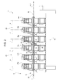
Figure 2 shows a frontal view of the unit ofFigure 1 , with a feeding group in a first position; -
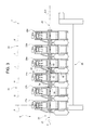
Figure 3 shows a frontal view of the unit ofFigure 1 , with the feeding group in a second position; -
Figure 4 is a perspective enlarged view of some components of the feeding group ofFigures 1 to 3 ; -
Figure 5 is a frontal view of the feeding group ofFigures 1 to 4 in the first position; -
Figure 6 is a frontal view of the feeding group ofFigures 1 to 5 in the second position; and -
Figure 7 schematically shows further components of the feeding group ofFigures 1 to 6 . -
Number 1 inFigure 1 indicates as a whole a unit for molding a plurality of opening devices 4 onto respective pre-laminated holes of aweb 3 of a packaging material. - Packaging material is intended to form a plurality of packages, which preferably contain a pourable food product, such as pasteurized or UHT milk, fruit juice, wine, etc.
- Packages may also contain a food product, which is pourable within a tube of packaging material when producing packages, and sets after packages are sealed. One example of such a food product is a portion of cheese, which is melted when producing packages and sets after packages are sealed.
- The tube is formed in known manner downstream from
unit 1 by longitudinally folding and sealing aknown web 3 of heat-seal sheet material, which comprises a layer of paper material covered on both sides with layers of heat-seal plastic material, e.g. polyethylene. In the case of an aseptic package for long-storage products, such as UHT milk, the packaging material comprises a layer of oxygen-barrier material, e.g. aluminium foil, which is superimposed on one or more layers of heat-seal plastic material eventually forming the inner face of package contacting the food product. - The tube of packaging material is then filled with the food product for packaging, and is sealed and cut along equally spaced cross sections to form a number of pillow packs (not shown), which are then transferred to a folding unit where they are folded mechanically to form respective packages.
- A first solution of opening device 4 comprises a patch defined by a small sheet of a heat-seal plastic material, and which is heat sealed over a respective hole on the side of the web eventually forming the inside of the package; and a pull-off tab applied to the opposite side of the packaging material and heat sealed to the patch. The tab and patch adhere to each other, so that, when the tab is pulled off, the portion of the patch heat sealed to it is also removed to uncover the hole.
- Alternatively, a second solution comprises closable opening devices 4 which are applied by injecting plastic material directly onto the holes of the
web 3. - In a third solution,
web 3 comprises a number of removable portions (only schematically shown inFigures 5 and6 ) equally spaced, except for the inevitable tolerance errors, in a lengthwise direction A parallel to an advancing path Y of the packaging material, and to which opening devices 4 are injection molded. - In the embodiment shown, the removable portion is defined by a so-called
pre-laminated hole -
Web 3 finally comprises a plurality of magnetic markers C1, C2, C3, C4, C5, C6 (shown inFigure 7 for sake of clarity, but not visible in reality). - More precisely, the positions of
pre-laminated holes - In the embodiment shown, magnetic markers C1, C2, C3, C4, C5, C6 are printed with a magnetizable ink which has been subsequently magnetized. More precisely, each magnetic marker C1, C2, C3, C4, C5, C6 has respective north and south poles aligned along path Y.
- Magnetic markers C1, C2, C3, C4, C5, C6 are applied to
web 3 in alignment withpre-laminated holes -
Unit 1 substantially comprises (Figure 1 ): - a
feeding group 6 arranged downstream of the reel and adapted tostepwise feed web 3 along direction A; and - a
molding station 26 stepwise fed withweb 3 bygroup 6 and adapted to injection mould opening devices 4 ontoweb 3 and at respectivepre-laminated holes web 3. - More precisely,
group 6 stepwise feeds one after the other a plurality ofportions 20 ofweb 3 each comprising a certain number ofpre-laminated holes molding station 26. - In particular,
portion 20 extends along direction A, when it is arrested undermolding station 26. - In detail, each
portion 20 comprises, in turn, proceeding along direction A and according to advancing sense ofweb 3 indicated by the arrow inFigures 1 to 7 : - a
stretch 21 comprising a first group, three in the embodiment shown, ofpre-laminated holes - a
stretch 22; and - a
stretch 23 comprising a second group, three in the embodiment shown, ofpre-laminated holes -
Molding station 26 comprises, in turn, proceeding along direction A and according to advancing direction of web 3: - a
group 25 ofmoulds web 3 and at respectivepre-laminate holes portion 20 has been arrested by feedinggroup 6; and - a
group 29 ofmoulds web 3 and at respectivepre-laminate holes portion 20 has been arrested by feedinggroup 6. - Each
mould pre-laminated hole portion 20 ofweb 3 is arrested (Figures 5 and6 ). - In other words, each axis F, G, H, I, J, K is the reference axis of respective injected opening devices 4.
- Axes F, G, H, I, J, K are orthogonal to direction A and
web 3 and, in the embodiment shown, vertical. - In the embodiment shown, the distance between axes F, I; G, J; H, K measured parallel to direction A equals length d (
Figure 5 ). - Furthermore, each
pre-laminated hole Figures 5 and6 ) about which respective opening device 4 should be ideally injected. - For each
pre-laminated holes - It is important to point out that due to the inevitable tolerance errors existing in the distance measured parallel to direction A between axes L, M, N, O, P, Q, it is not possible to simultaneously arrange all
pre-laminated holes - In the embodiment shown,
pre-laminated holes - In other words, the distances between consecutive axes L, M; M, N; N, O; O, P; P, Q measured parallel to direction A are equal.
-
Feeding group 6 comprises, in turn, proceeding parallel to advancing sense ofweb 3 parallel to direction A (Figure 1 ): - a
device 10 arranged downstream from the reel and adapted to create a tension inweb 3 along direction A; and - a
device 16 arranged downstream from themolding station 26 along path Y and adapted to advanceweb 3 along direction A in the sense indicate by the arrow inFigure 1 . -
Unit 1 also comprises a plurality of idler rollers 7 which are arranged upstream fromdevice 10 and downstream fromdevice 16 and are adapted to supportweb 3 while it advances along path Y. - In greater detail,
device 10 comprises (Figure 1 ): - a
motor 11 for providingweb 3 with the correct level of tension; - a plurality of
rollers 12 and counter-rollers (not shown) for guidingweb 3 along direction A; - a pair of
rollers 13 for damping the oscillations ofweb 3 in a vertical plane. -
Device 10 further comprises: - a magnetic sensor 15 (schematically shown in
Figure 7 ) arranged upstream ofmoulding station 26 with reference to the advancing sense ofweb 3, and adapted to detect the real positions of magnetic markers C1, C2, C3, C4, C5, C6 upstream ofmoulding station 26 and to generate respective measure signals M1, M2, M3, M4, M5, M6 associated to the real position ofpre-laminated holes moulding station 26; and - a magnetic sensor 100 (schematically shown in
Figure 7 ) interposed betweenmoulds moulds pre-laminated holes moulds -
Motor 11 exerts an action onweb 3 opposite to the action exerted bydevice 16, so as to provideweb 3 with the correct level of tension along direction A. -
Roller 12 is driven in rotation bymotor 11 through the interposition of abelt 8. More precisely,belt 8 is wound onto apulley 9a driven in rotation bymotor 11 and apulley 9b which drives inrotation roller 12. -
Roller 12 and corresponding counter-roller cooperate with opposite sides ofweb 3 which is being advanced towardsmolding station 26. -
Sensor 15, in the embodiment shown, detects the transition between respective north and south pole of magnetic markers C1, C2, C3, C4, C5, C6, so detecting the positions of magnetic markers C1, C2, C3, C4, C5, C6 and, therefore, the positions of relativepre-laminated holes -
Sensors pre-laminated holes moulding station 26 and betweenmoulds -
Device 16 comprises: - a fixed
frame 40; and - a motor 44 (shown in
Figure 1 ) fitted to frame 40 and adapted tostep-wise advance web 3 along direction A and on the opposite side ofmolding station 26. - Advantageously,
motor 44 ofdevice 16 is controllable to arrestweb 3 in a position, at which the distance between axes L, O; M, P; N, Q measured parallel to direction A equals length e (figure 5 ), and at whichpre-laminated holes Figure 5 ) with respect to the respective desired injection positions; andgroup 6 further comprises anactuator 50 controllable for movingpre-laminated holes - In other words,
motor 44 is controllable to arrestportion 20 ofweb 3 in a position, at which the distance between axis F, G, H ofpre-laminated holes moulds Figure 5 ), except for the inevitable tolerance errors existing in the distances between axes L, M; M, N. - It is important to point out that the expression intentional offset is used to indicate a distance intentionally left by feeding
group 6 between axis L, M, N and relative axis F, G, H. - In this respect, intentional offset X is different from the inevitable tolerance errors (not shown in
Figures 5 and6 ) existing in the distances between axis L, M; M, N; N, O. - In particular, the value of offset X is far greater than the inevitable tolerance errors existing in the distances between axis L, M; M, N; N, O of
pre-laminated holes - Furthermore, length e is measured when
portion 20 is flat and wholly lies on a plane parallel to direction A. - In the embodiment shown, length e is greater than length d.
- In particular, length e is not an integer multiple of length d.
- In the embodiment shown, length e is an integer multiple of the distance between axes L, M; M, N; N, O; O, P; P, Q of two consecutive
pre-laminated holes pre-laminated holes - It is important to point out that lengths e, d are in the present description nominal length, which are measured without taking into account the inevitable tolerances.
- Still more precisely, when
portion 20 is arrested,pre-laminated holes web 3 along direction A. - In other words, when
portion 20 is arrested, axes L, M, N of respectivepre-laminated holes respective moulds web 3 along direction A. - Furthermore,
motor 44 is controllable to arrestweb 3 withpre-laminated holes - Still more precisely, as it will be evident in the following of the present description,
motor 44 is controllable to arrestportion 20 in such a position that axis J ofpre-laminated holes 2e coincide with axis P ofrespective mould 28b and is, therefore, in the desired injection position. - Accordingly, the positions of axes O, Q of
pre-laminated holes respective moulds pre-laminated hole 2e in the desired injection position. - In light of the above,
pre-laminated holes - In particular, once
portion 20 has been arrested, the distance between axis O ofpre-laminated hole 2d and axis I ofmould 28a equals the inevitable tolerance error existing in the distance between axes O, P. - In the very same way, once
portion 20 has been arrested, the distance between axis Q ofpre-laminated hole 2f and axis K ofmould 28c equals the inevitable tolerance error existing in the distance between axes Q, P. - Due to the fact that these inevitable tolerance errors can be neglected, they are not visible in
Figures 5 and6 . - With reference to
Figure 6 ,actuator 50 is controllable to movepre-laminated hole 2b exactly in the respective desired injection position along direction A and in the same sense of the advancing sense ofweb 3, before the injection of respective opening devices 4. - In other words, actuator 50 is controllable to move
web 3 so as to render axis M ofpre-laminated hole 2b and axis G ofmould 27b coincident with one another, and recover offset X also ofpre-laminated holes - Accordingly, the positions of axes L, N of
pre-laminated holes moulds pre-laminated hole 2b in the desired injection position. - In particular,
actuator 50 is controllable to arrestweb 3 in a position at which the distance between axis L ofpre-laminated hole 2a and axis F ofmould 27a equals the inevitable tolerance error existing in the distance between axes L, M. - In the very same way,
actuator 50 is controllable to arrestweb 3 in a position at which the distance between axis N ofpre-laminated hole 2c and axis H ofmould 27c equals the inevitable tolerance error existing in the distance between axes N, L. - Furthermore,
actuator 50 is controllable to substantially leavepre-laminated holes web 3 has been arrested and before the injection of respective opening devices 4. - In this way,
pre-laminated hole 2e remains in the respective desired injection position with respect tomould 28b whereas thepre-laminated holes - In greater detail,
actuator 50 is interposed along direction A betweenmoulds moulds -
Actuator 50 substantially comprises (Figures 4 to 6 ) : - a
frame 46; - a pair of
rollers 51, which are arranged on aside 5a ofweb 3, cooperate withstretch 22 ofportion 20, and eccentrically rotate about a common axis B orthogonal to direction A and horizontal, in the embodiment shown; - a pair of
rollers 52, which are arranged on aside 5b ofweb 3, cooperate withstretch 22 ofportion 20, and rotate about a common axis C; and - a pair of
rollers 53, which are arranged onside 5b ofweb 3, cooperate withstretch 22 ofportion 20, and rotate about a common axis D. - In detail,
frame 46 comprises: - two
walls - a pair of
support elements wall 47b towardsmotor 44 and which rotatablysupport rollers 51 eccentrically about axis B. -
Walls -
Support elements - In particular,
wall 47b is arranged downstream ofwall 47a, proceeding along direction A according to the advancing sense ofweb 3. -
Side 5a is the upper side ofweb 3 andside 5b is the lower side ofweb 3, in the embodiment shown. -
Rollers 51 selectively rotate eccentrically about axis B between: - a first position (shown in
Figures 2 and5 ), at which they are tangent to the plane ofweb 3, and therefore leavestretch 22 coplanar with the remaining part ofweb 3 and substantially do not exert any action onstretch 22 ofweb 3; and - a second position (shown in
Figures 3 and6 ), at which they extend partly beyond the plane ofstretches web 3, and therefore interfere withstretch 22 andpress stretch 22 towardsrollers - As shown in
Figures 3 and6 , whenrollers 51 are set in the second position, stretch 22 forms aloop 80 housed inside aroom 81.Room 81 is interposed betweenrollers side 5b ofweb 3. - As a result, when
rollers 51 are set in the second position, stretch 21 ofportion 20 ofweb 3 withpre-laminated holes motor 44, thus recovering offset X up to reach the position shown inFigure 6 . - On the contrary, when
rollers 51 are set in the first position,stretch 22 is substantially un-deformed and does not occupyroom 81. Accordingly, stretch 21 remains stationary parallel to direction A. - It is important to point out that
rollers 51 can selectively assume a plurality of second positions. - For each second position, the extension of
loop 80 varies and therefore effective distances between axes G, M measured parallel to direction A of different lengths are recovered. - In the embodiment shown,
rollers 51 are arranged aboverollers - Furthermore,
rollers counter-support side 5b ofweb 3. - Axes C, D are parallel to each other, parallel to axis B and staggered with respect to direction A.
- In particular, axis C is arranged upstream of axis D, proceeding along direction A according to the advancing direction of
web 3. - Axis B is interposed between axes C, D, proceeding along direction A according to the advancing direction of
web 3 - Axes C, D define a plane, horizontal in the embodiment shown, and parallel to direction A.
- Axis B and axes C, D are arranged on
opposite sides web 3. -
Rollers -
Actuator 50 substantially comprises (Figure 4 ): - a
motor 55 controllable on the basis of offset X to be recovered; - a
pin 56 of axis B, rotatably supported insidesupport element 48a and driven in rotation about axis B bymotor 55; and - a
shaft 57 parallel to axis B, to which are idly fittedrollers 51 and eccentrically supported bypin 56 with respect to axis B. - In particular,
rollers 51 are rotatably mounted in an idle way onshaft 57 about their own axes parallel to and distinct from axis B, by not-shown bearings. - In the very same way, each
roller relative shaft 58 and about respective axis C, D, by not-shown bearings. -
Unit 1 also comprises a control unit 30 (only schematically shown inFigure 7 ) which receives measure signals M2 fromsensor 15 and generates control signal S1 formotor 55. - Furthermore,
control unit 30 receives measure signal M5' fromsensor 100 and generates control signal S2 formotor 44. - In particular,
control unit 30 has stored in memory the desired injection positions ofpre-laminated holes moulds pre-laminated holes web 3 is arrested. -
Control unit 30 is configured to generate control signal S1 formotor 55 on the basis of measured signal M2 and onceweb 3 has been arrested bydevice 16. - Control signal S1 for
motor 55 results in the rotation ofrollers 51 eccentrically about axis B in the second position, so as to pressstretch 22 towardsrollers form loop 80, which is housed inroom 81. - Accordingly, stretch 21 only of each
portion 20 is moved, dragged in the embodiment shown, along direction A and towardsmotor 44 for a distance, which is necessary to render axes M, G coincident and, therefore, to arrangepre-laminated hole 2b exactly in the desired injection position. - In this way, the operation of
actuator 50 recovers offset X ofpre-laminated holes - Furthermore,
control unit 30 is configured to generate control signal S2 formotor 44 on the basis of measured signal M5' detected bysensor 100. - In particular, control signal S2 for
motor 44 causes theweb 3 to be arrested in a position at which axis P ofpre-laminated hole 2e coincide with axis J ofmoulds 28b. - In this way,
pre-laminated hole 2e is arranged in respective desired injection position with axes J, P coincident. - Furthermore, the distances between axes I, K of
pre-laminated holes - The operation of
feeding group 6 and ofunit 1 will be hereinafter described with reference to only oneportion 20 and to the relativepre-laminated holes - The operation of
feeding group 6 will be furthermore described starting from a situation, at whichrollers 51 are in the first positions and, therefore, do not pressstretch 22 inside room 81 (Figures 2 and5 ). -
Web 3 provided withpre-laminated holes - In particular,
pre-laminated holes -
Motor 44 ofdevice 16 stepwise and horizontally advancesweb 3 along direction A and up to arrangeportion 20 belowmoulding station 26, while tensioningdevice 10 providesweb 3 with the correct level of tension. - As
web 3 advances along direction A,side 5a ofweb 3 causes the idle rotation ofrollers 51 about their own axis, which is distinct from and parallel to axis B. Furthermore,rollers side 5b ofweb 3 and are rotated, byweb 3, about respective axes C, D. -
Sensor 15 detects the presence of magnetic markers C1, C2, C3, C4, C5, C6 and generates measure signals M1, M2, M3, M4, M5, M6 which are associated to the real position ofpre-laminated holes moulding station 26. - In the very same way,
sensor 100 detects the presence of magnetic markers C1, C2, C3, C4, C5, C6 and generates measure signals M1', M2', M3', M4', M5', M6'. which are associated to the real position ofpre-laminated holes moulds -
Control unit 30 receives measured signal M5' associated to the real-position of axis P ofpre-laminated hole 2e; evaluates the difference between the real position of axis P and the desired injection position coincident with axis J, and generates control signal S2 formotor 44. - In particular,
motor 44 stopsweb 3 in a position (Figure 5 ), at which axis P ofpre-laminated hole 2e substantially coincides with axis J of mould 28e, i.e. substantially in the desired injection position ofpre-laminated hole 2e. - The positions of
pre-laminated holes stretch 23 whenweb 3 is arrested are determined by the desired injection position ofpre-laminated hole 2e. - In particular, the distance between axis O of
pre-laminated hole 2d and axis I ofmould 28a equals the inevitable tolerance error existing between axes O, P of respectivepre-laminated holes - In the very same way, the distance between axis Q of
pre-laminated hole 2f and axis K ofmould 28c equals the inevitable tolerance error existing between axes Q, P of respectivepre-laminated holes - Furthermore, when
motor 44 has arrested web 3 (Figure 5 ),pre-laminated holes stretch 21 are arranged with an intentional offset X with respect to desired injection positions. This is due to the fact that the difference between lengths e and d equals offset X. - On the contrary,
pre-laminated holes stretch 23 are arranged with no intentional offset with respect to the desired injection position. - Still more precisely, proceeding parallel to direction A, axis L (M, N) of
pre-laminated hole 2a (2b, 2c) is arranged upstream of axis F (G, H) ofmould 27a (27b, 27c), as shown inFigure 5 . - At this stage,
control unit 30 receives measured signal M2 associated to the real position ofpre-laminated holes 2b; evaluates the difference between the real position and the desired injection position ofpre-laminated hole 2b, and generates control signal S1 formotor 55. - In particular,
motor 55 rotatesrollers 51 eccentrically about axis B for a given angle associated to control signal S1. - More precisely,
motor 55drives rollers 51 in the second position, shown inFigures 2 and5 . - Due to the fact that they rotate eccentrically about axis B,
rollers 51, when set in the second position,press stretch 22 towardsrollers - Still more precisely, due to the rotation of
rollers 51,stretch 22forms loop 80 which occupies room 81 (Figure 5 ). - As a result,
stretch 21 is dragged towardsmotor 44 whereasstretch 23 remains fixed. - In this way, offset X of
pre-laminated holes - Furthermore,
pre-laminated hole 2b is arranged in the desired injection position, with axis M, G substantially coincident with one another. - The dragging of
stretch 21 also determines the position of axes L, N ofpre-laminated holes respective moulds - Still more precisely, the positions of
pre-laminated holes stretch 21 whenrollers 51 reach the second position, is determined by the position ofpre-laminated hole 2e. - In particular, the distance between axis L of
pre-laminated hole 2a and axis F ofmould 27a equals the inevitable tolerance error existing between axes L, M of respectivepre-laminated holes - In the very same way, the distance between axis N of
pre-laminated hole 2c and axis H ofmould 27c equals the inevitable tolerance error existing between axes N, M of respectivepre-laminated holes - At this stage,
moulds pre-laminated holes - Afterwards,
motor 55 rotates backrollers 51 in the first position (Figures 2 and5 ), andweb 3 is advanced, so as to arrange anew portion 20 belowmoulding station 26. - The advantages of
feeding group 6 and of the method according to the present invention will be clear from the foregoing description. - In particular,
devices web 3 in a position, at whichpre-laminated holes actuator 50moves web 3, so as to recover offset X and arrangepre-laminated hole 2b in the desired injection position. - In particular, in the above-identified arrest position, the difference between length e and length d equals offset X.
- In this way, it is possible to ensure that, when moulding injection is carried out,
pre-laminated hole 2b is in the desired injection position and thatpre-laminated holes - Moreover,
actuator 50 movespre-laminated holes pre-laminated holes - Accordingly, the tolerance chain formed by the tolerance errors in the distances between axes L, M and M, N of
pre-laminated holes pre-laminated holes - Therefore, feeding
group 6 can feedmoulding station 26 with bothpre-laminated holes pre-laminated holes pre-laminated holes respective moulds - The feeding rate of
feeding group 6 is therefore enhanced, without penalizing the precision of the positioning ofpre-laminated holes - Furthermore,
actuator 50 comprisesrollers 51, which rotate eccentrically about axis B from the first position at which are tangent to advancingweb 3 to the second position at which they pressstretch 22 of arrestedweb 3 inroom 81 so as to recover offset X. - Accordingly,
rollers 51 efficiently recover offset X when set in the second position without damagingweb 3 when set in the first position. - Clearly, changes may be made to
feeding group 6 and to the method without, however, departing from the protective scope defined in the accompanying Claims. - In particular,
unit 1 could comprise at least two tools different frommoulds web 3 different frompre-laminated holes actuator 50 being interposed along direction A between those two tools. - Furthermore,
actuator 50 could be a linear push element, which can be selectively moved in a position at which pushesstretch 22 ofweb 3 insideroom 81. - Markers C1, C2, C3, C4, C5, C6 could be not magnetic. For example, they could be formed by respective optically-readable printed marks.
- Finally, length e could be smaller than length d and offset X could be equal to d-e.
Claims (15)
- A unit (1) for carrying out a first operation and a second operation respectively onto a first area (2d, 2e, 2f) and a second area (2a, 2b, 2c) of a packaging material;
said first area (2d, 2e, 2f) and said second area (2a, 2b, 2c) being spaced for a first distance (e) along said direction (A) when a portion (20) of said packaging material comprising said first area (2d, 2e, 2f) and said second area (2a, 2b, 2c) is flat;
said unit (1) comprising:- a feeding group (6) for feeding a web (3) of said packaging material along a direction (A) and in a first sense;- at least one first tool (28a, 28b, 28c) adapted to carry out said first operation on said first area (2d, 2e, 2f) arranged in a first desired position;- at least one second tool (27a, 27b, 27c) adapted to carry out said second operation on said second area (2d, 2e, 2f) arranged in a second desired position;said first (28a, 28b, 28c) and said second tool (27a, 27b, 27c) being spaced for a second distance (d) along said direction (A);
characterized in that said feeding group (6) comprises:- advancing means (10, 16) controllable to arrest said web (3) in a position, at which said second area (2a, 2b, 2c) is spaced for an intentional offset (X) from said second desired position; and- actuating means (50) controllable for moving said second area (2a, 2b, 2c) towards said second desired position, so as to recover said offset (X);the absolute value of the difference between said first distance (e) and said second distance (d) being equal to said offset (X). - The unit of claim 1, characterized in that said actuating means (50) are controllable to move said second area (2a, 2b, 2c) towards said second desired position, parallel to said direction (A) and in said first sense.
- The unit of claim 1 or 2, characterized in that said advancing means (10, 16) are controllable to arrest said first area (2d, 2e, 2f) in said first desired position; and in that said actuating means (50) are controllable to substantially leave said first area (2d, 2e, 2f) in said first desired position.
- The unit of any one of the foregoing claims, characterized in that said actuating means (50) comprise at least one moving member (51), which may move between:- a first position, at which it does not interact with said web (3); and- a second position, at which it presses said web (3) so as to move said second area (2a, 2b, 2c) towards said second desired position, when said web (3) has been arrested by said advancing means (10, 16).
- The unit of claim 4, characterized in that said moving member (51) is a rotating member (51) that rotates eccentrically about a first axis (B) between said first position and said second position;
said actuating means (50) comprising at least a pair of rollers (52, 53) arranged, in use, on the opposite side of said rotating member (51) with respect to said web (3) and adapted to counter-support said web (3) against said rotating member (51);
said rollers (52, 53) having respective second axes (C, D) spaced along said direction (A);
said first axis (B) being interposed between said second axes (C, D), so that the eccentric rotation of said rotating member (51) presses a portion (22) of said web (3) in a room (81) defined between said second axes (C, D) and arranged on the opposite side of said web (3) with respect to said first rotating member (51). - The unit of any one of the foregoing claims, characterized by comprising sensing means (15) for generating a signal (S1) associated to the real position of said second area (2a, 2b, 2c); said actuating means (50) being controllable on the basis of said signal (S1) to move said second area (2a, 2b, 2c) towards said second desired position.
- The unit of any one of the foregoing claims, characterized in that said actuating means (50) are arranged upstream of said second tool (27a, 27b, 27c) and downstream of said first tool (28a, 28b, 28c), proceeding along said direction (A) according to said first sense.
- The unit of any one of the foregoing claims, characterized in that said first tool (28a, 28b, 28c) is a first applicator for applying a first opening device (4) onto said first area (2d, 2e, 2f) and in said first desired position, and in that said second tool (27a, 27b, 27c) is a second applicator for applying a second opening device (4) onto said second area (2a, 2b, 2c).
- A method for carrying out a first operation and a second operation respectively onto a first area (2d, 2e, 2f) and a second area (2a, 2b, 2c) of a packaging material;
said first area (2d, 2e, 2f) and said second area (2a, 2b, 2c) being spaced for a first distance (e) along said direction (A) when a portion (20) of said packaging material comprising said first area (2d, 2e, 2f) and said second area (2a, 2b, 2c) is flat;
said method comprising the steps of:- feeding a web (3) of said packaging material along a direction (A) and in a first sense;- carrying out said first operation on said first area (2d, 2e, 2f) and at a first desired position, by using at least one first tool (28a, 28b, 28c); and- carrying out said second operation on said second area (2a, 2b, 2c) and at a second desired position, by using at least one second tool (27a, 27b, 27c);said first (28a, 28b, 28c) and said second tool (27a, 27b, 27c) being spaced for a second distance (d) along a direction (A);
characterized in that said step of feeding comprises the steps of:- arresting said web (3) in a position, at which said second area (2a, 2b, 2c) is spaced by an intentional offset (X) from said second desired position; and- moving said second area (2a, 2b, 2c) towards said second desired position, so as to recover said offset (X);the absolute value of the difference between said first distance (e) and said second distance (d) being equal to said offset (X). - The method of claim 9, characterized in that said step of moving comprises the step of dragging said second area (2a, 2b, 2c) in said first sense and along said direction (A).
- The method of claim 9 or 10, characterized in that said step of feeding comprises the step of arresting said first area (2d, 2e, 2f) in said first desired position; and in that said step of moving said second area (2a, 2b, 2c) comprises the step of substantially leaving said first area (2d, 2e, 2f) in said first desired position.
- The method of claim 10 or 11, characterized in that said step of dragging comprises the steps of:- pressing a portion (22) of said web (3) interposed between said first area (2d, 2e, 2f) and said second area (2a, 2b, 2c), by moving a movable element (51) between a first position, at which said movable element (51) does not interact with said web (3), and a second position, at which movable element (51) presses said web (3).
- The method of claim 12, characterized in that said step of dragging comprises the step of eccentrically rotating said movable element (51) about a first axis (B) and between said first position and said second position; the method further comprising the step of:- supporting said portion (22) of said web (3), by using a pair of rollers (52, 53) rotatable about respective second axes (C, D), spaced along said direction (A), and arranged on the opposite side of said movable element (51) with respect to said web (3),
said step of pressing comprising the step of forcing said portion (22) in a room (81) defined between said second axes (C, D) and arranged on the opposite side of said web (3) with respect to said element (51). - The method of any one of claims 9 to 13, characterized by comprising the steps of:- carrying out a plurality of said second operations on respective said second areas (2a, 2b, 2c), by using a plurality of respective said second tools (27a, 27b, 27c);- arranging, during said step of moving, one (2b) of said second areas (2a, 2b, 2c) in respective said second desired position; and- arranging, during said step of moving, the others (2a, 2c) of said second areas (2a, 2b, 2c) in respective positions determined by said desired position of said one (2b) of said second areas (2a, 2b, 2c).
- The method of any one of claims 9 to 14, characterized in that said step of carrying out said first operation on said first area (2d, 2e, 2f) comprises the step of applying a first opening device (4) on said first area (2d, 2e, 2f), and in that said step of carrying out said second operation on said second area (2a, 2b, 2c) comprises the step of applying a second opening device (4) on said second area (2a, 2b, 2c).
Priority Applications (11)
| Application Number | Priority Date | Filing Date | Title |
|---|---|---|---|
| EP13184222.1A EP2848399B1 (en) | 2013-09-13 | 2013-09-13 | A unit and a method for carrying out a first operation and a second operation on a web |
| ES13184222.1T ES2645422T3 (en) | 2013-09-13 | 2013-09-13 | A unit and a method for carrying out a first operation and a second operation in a band |
| NO13184222A NO2848399T3 (en) | 2013-09-13 | 2013-09-13 | |
| KR1020167005880A KR20160057390A (en) | 2013-09-13 | 2014-08-01 | A unit and a method for carrying out a first operation and a second operation on a web |
| RU2016113709A RU2636006C2 (en) | 2013-09-13 | 2014-08-01 | Device and method for first operation and second operation on web |
| MX2016001525A MX2016001525A (en) | 2013-09-13 | 2014-08-01 | A unit and a method for carrying out a first operation and a second operation on a web. |
| US14/912,031 US10286583B2 (en) | 2013-09-13 | 2014-08-01 | Unit and a method for carrying out a first operation and a second operation on a web |
| CN201480044722.5A CN105473322B (en) | 2013-09-13 | 2014-08-01 | Unit and method for performing a first operation and a second operation on a web |
| PCT/EP2014/066625 WO2015036169A1 (en) | 2013-09-13 | 2014-08-01 | A unit and a method for carrying out a first operation and a second operation on a web |
| JP2016541854A JP6499181B2 (en) | 2013-09-13 | 2014-08-01 | Unit and method for applying a first process and a second process to a web |
| BR112016002506A BR112016002506A2 (en) | 2013-09-13 | 2014-08-01 | unit and method for performing a first operation and a second operation respectively on a first area and a second area of a packing material |
Applications Claiming Priority (1)
| Application Number | Priority Date | Filing Date | Title |
|---|---|---|---|
| EP13184222.1A EP2848399B1 (en) | 2013-09-13 | 2013-09-13 | A unit and a method for carrying out a first operation and a second operation on a web |
Publications (2)
| Publication Number | Publication Date |
|---|---|
| EP2848399A1 true EP2848399A1 (en) | 2015-03-18 |
| EP2848399B1 EP2848399B1 (en) | 2017-09-13 |
Family
ID=49209236
Family Applications (1)
| Application Number | Title | Priority Date | Filing Date |
|---|---|---|---|
| EP13184222.1A Active EP2848399B1 (en) | 2013-09-13 | 2013-09-13 | A unit and a method for carrying out a first operation and a second operation on a web |
Country Status (11)
| Country | Link |
|---|---|
| US (1) | US10286583B2 (en) |
| EP (1) | EP2848399B1 (en) |
| JP (1) | JP6499181B2 (en) |
| KR (1) | KR20160057390A (en) |
| CN (1) | CN105473322B (en) |
| BR (1) | BR112016002506A2 (en) |
| ES (1) | ES2645422T3 (en) |
| MX (1) | MX2016001525A (en) |
| NO (1) | NO2848399T3 (en) |
| RU (1) | RU2636006C2 (en) |
| WO (1) | WO2015036169A1 (en) |
Cited By (2)
| Publication number | Priority date | Publication date | Assignee | Title |
|---|---|---|---|---|
| EP3822071A1 (en) | 2019-11-13 | 2021-05-19 | Tetra Laval Holdings & Finance S.A. | Unit and method for applying opening devices to a web of packaging material |
| IT202400006760A1 (en) | 2024-03-26 | 2025-09-26 | Tetra Laval Holdings & Finance | METHOD AND UNIT FOR THE APPLICATION OF OPENING DEVICES ON A STRIP OF PACKAGING MATERIAL |
Families Citing this family (2)
| Publication number | Priority date | Publication date | Assignee | Title |
|---|---|---|---|---|
| DE102016218190A1 (en) * | 2016-09-22 | 2018-03-22 | Robert Bosch Gmbh | Apparatus and method for producing a bag package |
| IT201800003287A1 (en) * | 2018-03-05 | 2019-09-05 | V Shapes S R L | ENGRAVING STATION FOR PACKAGING MACHINE AND RELATIVE ENGRAVING METHOD |
Citations (3)
| Publication number | Priority date | Publication date | Assignee | Title |
|---|---|---|---|---|
| US6386851B1 (en) * | 1999-12-22 | 2002-05-14 | Tetra Laval Holdings & Finance S.A. | Multi-stage unit for processing a web packaging material in a food product packaging machine |
| JP2004106431A (en) * | 2002-09-20 | 2004-04-08 | Otsuka Pharmaceut Factory Inc | Method and apparatus for controlling feeding and processing of strip film raw material |
| EP2357138A1 (en) | 2010-02-12 | 2011-08-17 | Tetra Laval Holdings & Finance S.A. | Device and method for feeding a web of a packaging material |
Family Cites Families (53)
| Publication number | Priority date | Publication date | Assignee | Title |
|---|---|---|---|---|
| US3126431A (en) * | 1964-03-24 | harder etal | ||
| US2638037A (en) * | 1947-08-29 | 1953-05-12 | Hoague Sprague Corp | Apparatus for feeding webs |
| US3044532A (en) * | 1960-03-30 | 1962-07-17 | Vita Mayer & Co Inc | Tail sealing machine |
| US3087393A (en) * | 1960-04-04 | 1963-04-30 | American Can Co | Machine and method for manufacturing fibrous container bodies |
| US3556510A (en) * | 1968-08-21 | 1971-01-19 | Harris Intertype Corp | Automatic web tension and register control |
| US3652363A (en) * | 1969-10-23 | 1972-03-28 | Phillips Petroleum Co | Film positioning apparatus |
| FR2214294A5 (en) * | 1973-01-11 | 1974-08-09 | Etudes De Machines Speciales | |
| US3861983A (en) * | 1973-02-12 | 1975-01-21 | Phillips Petroleum Co | Film positioning apparatus |
| CH650722A5 (en) * | 1983-02-21 | 1985-08-15 | Bobst Sa | MACHINE FOR MAKING FOLDING BOXES. |
| EP0216964A1 (en) * | 1985-08-27 | 1987-04-08 | Hiroshi Kataoka | Take-out/take-up tension control apparatus |
| SE8600365L (en) | 1986-01-28 | 1987-07-29 | Tetra Pak Int | SET AND DEVICE FOR PROMOTING A MATERIAL COVER |
| CH665999A5 (en) * | 1986-03-17 | 1988-06-30 | Bobst Sa | METHOD AND DEVICE FOR CONTROLLING THE ADJUSTMENT OF THE ORGANS OF A MACHINE FOR GRAPHIC ARTS AND CARDBOARDING. |
| US5011722A (en) * | 1988-05-13 | 1991-04-30 | Chung Packaging Company | Rectangular paperboard package and method of making same |
| US4759741A (en) * | 1986-10-08 | 1988-07-26 | Specialty Equipment Corporation | Vari-gap drive system for box folders and the like |
| US4846915A (en) * | 1988-03-08 | 1989-07-11 | International Paper Company | Apparatus for indexing and feeding a fitment web and related method |
| US5000725A (en) * | 1988-11-07 | 1991-03-19 | Fmc Corporation | Bi-directional registration of servo indexed webs |
| US5150560A (en) * | 1991-06-12 | 1992-09-29 | Roll Systems, Inc. | System and method for manufacturing envelopes |
| US5383392A (en) * | 1993-03-16 | 1995-01-24 | Ward Holding Company, Inc. | Sheet registration control |
| JP3464814B2 (en) * | 1993-12-28 | 2003-11-10 | 日本テトラパック株式会社 | Spout forming device in packaging machine |
| US5803888A (en) * | 1994-08-19 | 1998-09-08 | Baxter International Inc. | Multi-web carrier |
| US5711470A (en) * | 1994-12-01 | 1998-01-27 | The North American Manufacturing Company | Apparatus and method for adjusting the lateral position of a moving strip |
| DE69629744T2 (en) * | 1995-03-20 | 2004-04-08 | Fuji Photo Film Co., Ltd., Minami-Ashigara | Method and device for producing discs |
| US20020000143A1 (en) * | 1995-04-10 | 2002-01-03 | Frank Okonski | Material jam clearing in an impression system |
| IT1286073B1 (en) * | 1996-10-31 | 1998-07-07 | Tetra Laval Holdings & Finance | EQUIPMENT AND PROCEDURE FOR PRINTING AN OPENER DEVICE ON A PACKING SHEET |
| US5733236A (en) * | 1996-12-19 | 1998-03-31 | Fmc Corporation | Bag-making apparatus having automated positioning of attachments |
| US5927196A (en) * | 1997-07-24 | 1999-07-27 | Heidelberger Druckmaschinen | Post chill dancer roll |
| US6024683A (en) * | 1998-03-09 | 2000-02-15 | Wilkes; Kenneth R. | Apparatus and method for fabricating containers |
| DE19913855A1 (en) * | 1999-03-26 | 2000-09-28 | Focke & Co | Method and device for printing blanks |
| FR2811254B1 (en) * | 2000-07-06 | 2003-02-14 | Rapidex Sm | SHEET PROCESSING MACHINE FOR MANUFACTURING PACKAGING |
| EP1170217B1 (en) * | 2000-07-07 | 2003-06-11 | Tetra Laval Holdings & Finance S.A. | Unit for processing a web of packaging material for producing sealed packages of pourable food products |
| CN1109628C (en) | 2000-08-22 | 2003-05-28 | 杨胜荣 | Feeder sensing compensation alignment device |
| NL1016524C2 (en) * | 2000-11-01 | 2002-05-07 | Aquarius Bv | Forming, filling and closing machine. |
| ATE296229T1 (en) * | 2000-11-24 | 2005-06-15 | Cfs Germany Gmbh | METHOD AND DEVICE FOR POSITIONING FILM WEAVES OF A PACKAGING DEVICE |
| AU2002338674A1 (en) * | 2001-09-14 | 2003-04-01 | Focke And Co. (Gmbh And Co.) | Packing with a tear strip and device for production thereof |
| JP2004074642A (en) * | 2002-08-20 | 2004-03-11 | Komori Corp | Rotary printing press |
| DE10335887B4 (en) * | 2003-08-06 | 2007-11-08 | Man Roland Druckmaschinen Ag | Method and apparatus for controlling a cut register error and web tension of a web-fed rotary press |
| DE10335888B4 (en) * | 2003-08-06 | 2008-03-13 | Man Roland Druckmaschinen Ag | Method and apparatus for controlling the total cut register error of a web-fed rotary press |
| DE10335885A1 (en) * | 2003-08-06 | 2005-03-17 | Man Roland Druckmaschinen Ag | Method and device for regulating the web tension and the cutting register error of a web-fed rotary printing press |
| SE0302493D0 (en) | 2003-09-19 | 2003-09-19 | Tetra Laval Holdings & Finance | Ways of controllably transporting an object and devices for transporting runway |
| ITTO20060009U1 (en) | 2006-01-13 | 2007-07-14 | Tetra Laval Holdings & Finance | SEQUENCER GROUP FOR PACKAGING OF VERSABLE FOOD PRODUCTS |
| ES2319564T3 (en) * | 2006-10-19 | 2009-05-08 | TETRA LAVAL HOLDINGS & FINANCE SA | MANUFACTURING PROCEDURE OF SEALED CONTAINERS CONTAINING A VERTIBLE FOOD PRODUCT AND INSTALLATION TO CARRY OUT SUCH PROCEDURE. |
| JP5173341B2 (en) * | 2007-09-26 | 2013-04-03 | 三菱重工印刷紙工機械株式会社 | Defective product removal device for box making machine and box making machine |
| JP4429352B2 (en) * | 2007-10-31 | 2010-03-10 | 株式会社三共製作所 | Sheet material feeder |
| FR2937897B1 (en) * | 2008-11-03 | 2010-11-12 | Rapidex Sm | EQUERING DEVICE FOR A PACKAGING LINE |
| US8900680B2 (en) * | 2009-05-29 | 2014-12-02 | Tetra Laval Holdings & Finanace S.A. | Packaging material comprising magnetisable portions |
| JP5538866B2 (en) * | 2009-12-22 | 2014-07-02 | キヤノン株式会社 | Image forming apparatus |
| JP2011241011A (en) * | 2010-05-14 | 2011-12-01 | Canon Electronics Inc | Sheet feeding device |
| JP2011245730A (en) * | 2010-05-26 | 2011-12-08 | Npc Inc | Laminator and method for attaching diaphragm sheet |
| JP6107317B2 (en) * | 2013-03-29 | 2017-04-05 | セイコーエプソン株式会社 | Recording device, transport device |
| US9044974B1 (en) * | 2014-02-18 | 2015-06-02 | Xerox Corporation | System and method for online web control in a tandem web printing system |
| JP6478084B2 (en) * | 2014-03-20 | 2019-03-06 | 日本電気硝子株式会社 | Glass film conveying method and glass film conveying apparatus |
| JP6608635B2 (en) * | 2015-07-13 | 2019-11-20 | 株式会社三共製作所 | Sheet material feeder |
| JP6613174B2 (en) * | 2016-02-29 | 2019-11-27 | リンテック株式会社 | Sheet sticking device and sticking method |
-
2013
- 2013-09-13 NO NO13184222A patent/NO2848399T3/no unknown
- 2013-09-13 ES ES13184222.1T patent/ES2645422T3/en active Active
- 2013-09-13 EP EP13184222.1A patent/EP2848399B1/en active Active
-
2014
- 2014-08-01 BR BR112016002506A patent/BR112016002506A2/en not_active Application Discontinuation
- 2014-08-01 CN CN201480044722.5A patent/CN105473322B/en active Active
- 2014-08-01 WO PCT/EP2014/066625 patent/WO2015036169A1/en not_active Ceased
- 2014-08-01 US US14/912,031 patent/US10286583B2/en active Active
- 2014-08-01 MX MX2016001525A patent/MX2016001525A/en unknown
- 2014-08-01 JP JP2016541854A patent/JP6499181B2/en active Active
- 2014-08-01 KR KR1020167005880A patent/KR20160057390A/en not_active Withdrawn
- 2014-08-01 RU RU2016113709A patent/RU2636006C2/en not_active IP Right Cessation
Patent Citations (3)
| Publication number | Priority date | Publication date | Assignee | Title |
|---|---|---|---|---|
| US6386851B1 (en) * | 1999-12-22 | 2002-05-14 | Tetra Laval Holdings & Finance S.A. | Multi-stage unit for processing a web packaging material in a food product packaging machine |
| JP2004106431A (en) * | 2002-09-20 | 2004-04-08 | Otsuka Pharmaceut Factory Inc | Method and apparatus for controlling feeding and processing of strip film raw material |
| EP2357138A1 (en) | 2010-02-12 | 2011-08-17 | Tetra Laval Holdings & Finance S.A. | Device and method for feeding a web of a packaging material |
Cited By (8)
| Publication number | Priority date | Publication date | Assignee | Title |
|---|---|---|---|---|
| EP3822071A1 (en) | 2019-11-13 | 2021-05-19 | Tetra Laval Holdings & Finance S.A. | Unit and method for applying opening devices to a web of packaging material |
| WO2021094113A1 (en) | 2019-11-13 | 2021-05-20 | Tetra Laval Holdings & Finance S.A. | Unit and method for applying opening devices to a web of packaging material |
| CN114728484A (en) * | 2019-11-13 | 2022-07-08 | 利乐拉瓦尔集团及财务有限公司 | Unit and method for applying opening devices to a web of packaging material |
| US12103262B2 (en) | 2019-11-13 | 2024-10-01 | Tetra Laval Holdings & Finance S.A. | Unit and method for applying opening devices to a web of packaging material |
| CN114728484B (en) * | 2019-11-13 | 2025-09-23 | 利乐拉瓦尔集团及财务有限公司 | Unit and method for applying an opening device to a web of packaging material |
| IT202400006760A1 (en) | 2024-03-26 | 2025-09-26 | Tetra Laval Holdings & Finance | METHOD AND UNIT FOR THE APPLICATION OF OPENING DEVICES ON A STRIP OF PACKAGING MATERIAL |
| WO2025201999A1 (en) | 2024-03-26 | 2025-10-02 | Tetra Laval Holdings & Finance S.A. | Method and unit for applying opening devices on a web of packaging material |
| EP4647249A1 (en) | 2024-03-26 | 2025-11-12 | Tetra Laval Holdings & Finance S.A. | Method and unit for applying opening devices on a web of packaging material |
Also Published As
| Publication number | Publication date |
|---|---|
| JP2016530173A (en) | 2016-09-29 |
| JP6499181B2 (en) | 2019-04-10 |
| RU2016113709A (en) | 2017-10-18 |
| ES2645422T3 (en) | 2017-12-05 |
| MX2016001525A (en) | 2016-06-23 |
| US20160193798A1 (en) | 2016-07-07 |
| CN105473322B (en) | 2018-02-13 |
| NO2848399T3 (en) | 2018-02-10 |
| US10286583B2 (en) | 2019-05-14 |
| KR20160057390A (en) | 2016-05-23 |
| CN105473322A (en) | 2016-04-06 |
| WO2015036169A1 (en) | 2015-03-19 |
| EP2848399B1 (en) | 2017-09-13 |
| BR112016002506A2 (en) | 2017-08-01 |
| RU2636006C2 (en) | 2017-11-17 |
Similar Documents
| Publication | Publication Date | Title |
|---|---|---|
| EP1914168B1 (en) | Process of manufacturing sealed packages containing a pourable food product and packaging equipment for performing such process | |
| EP2357138B1 (en) | Device and method for feeding a web of a packaging material | |
| EP2944458B1 (en) | Sheet of packaging material for producing a container and method for producing containers | |
| EP2935024B1 (en) | Unit for the application of opening devices on sealed packages of food products | |
| EP3081497B1 (en) | Packaging machine and method for producing packages from a packaging material | |
| US10286583B2 (en) | Unit and a method for carrying out a first operation and a second operation on a web | |
| US7033310B2 (en) | Unit for processing a web of packaging material | |
| EP3141488B1 (en) | Packaging machine for producing packages from a sheet of packaging material | |
| WO2002004312A1 (en) | Packaging material for packaging pourable food products, and package made therefrom | |
| EP1110867B1 (en) | Multi-stage unit for processing a web packaging material in a food product packaging machine | |
| US12103262B2 (en) | Unit and method for applying opening devices to a web of packaging material | |
| HK1177448A (en) | Device and method for feeding a web of a packaging material |
Legal Events
| Date | Code | Title | Description |
|---|---|---|---|
| PUAI | Public reference made under article 153(3) epc to a published international application that has entered the european phase |
Free format text: ORIGINAL CODE: 0009012 |
|
| 17P | Request for examination filed |
Effective date: 20130913 |
|
| AK | Designated contracting states |
Kind code of ref document: A1 Designated state(s): AL AT BE BG CH CY CZ DE DK EE ES FI FR GB GR HR HU IE IS IT LI LT LU LV MC MK MT NL NO PL PT RO RS SE SI SK SM TR |
|
| AX | Request for extension of the european patent |
Extension state: BA ME |
|
| R17P | Request for examination filed (corrected) |
Effective date: 20150918 |
|
| RBV | Designated contracting states (corrected) |
Designated state(s): AL AT BE BG CH CY CZ DE DK EE ES FI FR GB GR HR HU IE IS IT LI LT LU LV MC MK MT NL NO PL PT RO RS SE SI SK SM TR |
|
| STAA | Information on the status of an ep patent application or granted ep patent |
Free format text: STATUS: EXAMINATION IS IN PROGRESS |
|
| 17Q | First examination report despatched |
Effective date: 20161104 |
|
| REG | Reference to a national code |
Ref country code: DE Ref legal event code: R079 Ref document number: 602013026479 Country of ref document: DE Free format text: PREVIOUS MAIN CLASS: B31B0001100000 Ipc: B31B0050100000 |
|
| GRAP | Despatch of communication of intention to grant a patent |
Free format text: ORIGINAL CODE: EPIDOSNIGR1 |
|
| STAA | Information on the status of an ep patent application or granted ep patent |
Free format text: STATUS: GRANT OF PATENT IS INTENDED |
|
| RIC1 | Information provided on ipc code assigned before grant |
Ipc: B29C 45/14 20060101ALN20170419BHEP Ipc: B65H 23/188 20060101ALI20170419BHEP Ipc: B31B 50/10 20170101AFI20170419BHEP Ipc: B29C 45/17 20060101ALN20170419BHEP Ipc: B31B 50/84 20170101ALI20170419BHEP Ipc: B65H 20/02 20060101ALN20170419BHEP Ipc: B65H 23/04 20060101ALI20170419BHEP Ipc: B65H 20/24 20060101ALN20170419BHEP |
|
| INTG | Intention to grant announced |
Effective date: 20170522 |
|
| GRAS | Grant fee paid |
Free format text: ORIGINAL CODE: EPIDOSNIGR3 |
|
| GRAA | (expected) grant |
Free format text: ORIGINAL CODE: 0009210 |
|
| STAA | Information on the status of an ep patent application or granted ep patent |
Free format text: STATUS: THE PATENT HAS BEEN GRANTED |
|
| AK | Designated contracting states |
Kind code of ref document: B1 Designated state(s): AL AT BE BG CH CY CZ DE DK EE ES FI FR GB GR HR HU IE IS IT LI LT LU LV MC MK MT NL NO PL PT RO RS SE SI SK SM TR |
|
| REG | Reference to a national code |
Ref country code: GB Ref legal event code: FG4D |
|
| REG | Reference to a national code |
Ref country code: CH Ref legal event code: EP |
|
| REG | Reference to a national code |
Ref country code: FR Ref legal event code: PLFP Year of fee payment: 5 |
|
| REG | Reference to a national code |
Ref country code: IE Ref legal event code: FG4D |
|
| REG | Reference to a national code |
Ref country code: AT Ref legal event code: REF Ref document number: 927720 Country of ref document: AT Kind code of ref document: T Effective date: 20171015 |
|
| REG | Reference to a national code |
Ref country code: DE Ref legal event code: R096 Ref document number: 602013026479 Country of ref document: DE |
|
| REG | Reference to a national code |
Ref country code: ES Ref legal event code: FG2A Ref document number: 2645422 Country of ref document: ES Kind code of ref document: T3 Effective date: 20171205 |
|
| REG | Reference to a national code |
Ref country code: SE Ref legal event code: TRGR |
|
| REG | Reference to a national code |
Ref country code: NL Ref legal event code: FP |
|
| REG | Reference to a national code |
Ref country code: LT Ref legal event code: MG4D |
|
| PG25 | Lapsed in a contracting state [announced via postgrant information from national office to epo] |
Ref country code: HR Free format text: LAPSE BECAUSE OF FAILURE TO SUBMIT A TRANSLATION OF THE DESCRIPTION OR TO PAY THE FEE WITHIN THE PRESCRIBED TIME-LIMIT Effective date: 20170913 Ref country code: LT Free format text: LAPSE BECAUSE OF FAILURE TO SUBMIT A TRANSLATION OF THE DESCRIPTION OR TO PAY THE FEE WITHIN THE PRESCRIBED TIME-LIMIT Effective date: 20170913 Ref country code: FI Free format text: LAPSE BECAUSE OF FAILURE TO SUBMIT A TRANSLATION OF THE DESCRIPTION OR TO PAY THE FEE WITHIN THE PRESCRIBED TIME-LIMIT Effective date: 20170913 |
|
| REG | Reference to a national code |
Ref country code: AT Ref legal event code: MK05 Ref document number: 927720 Country of ref document: AT Kind code of ref document: T Effective date: 20170913 |
|
| REG | Reference to a national code |
Ref country code: NO Ref legal event code: T2 Effective date: 20170913 |
|
| PG25 | Lapsed in a contracting state [announced via postgrant information from national office to epo] |
Ref country code: LV Free format text: LAPSE BECAUSE OF FAILURE TO SUBMIT A TRANSLATION OF THE DESCRIPTION OR TO PAY THE FEE WITHIN THE PRESCRIBED TIME-LIMIT Effective date: 20170913 Ref country code: RS Free format text: LAPSE BECAUSE OF FAILURE TO SUBMIT A TRANSLATION OF THE DESCRIPTION OR TO PAY THE FEE WITHIN THE PRESCRIBED TIME-LIMIT Effective date: 20170913 Ref country code: BG Free format text: LAPSE BECAUSE OF FAILURE TO SUBMIT A TRANSLATION OF THE DESCRIPTION OR TO PAY THE FEE WITHIN THE PRESCRIBED TIME-LIMIT Effective date: 20171213 Ref country code: GR Free format text: LAPSE BECAUSE OF FAILURE TO SUBMIT A TRANSLATION OF THE DESCRIPTION OR TO PAY THE FEE WITHIN THE PRESCRIBED TIME-LIMIT Effective date: 20171214 |
|
| PG25 | Lapsed in a contracting state [announced via postgrant information from national office to epo] |
Ref country code: CZ Free format text: LAPSE BECAUSE OF FAILURE TO SUBMIT A TRANSLATION OF THE DESCRIPTION OR TO PAY THE FEE WITHIN THE PRESCRIBED TIME-LIMIT Effective date: 20170913 Ref country code: RO Free format text: LAPSE BECAUSE OF FAILURE TO SUBMIT A TRANSLATION OF THE DESCRIPTION OR TO PAY THE FEE WITHIN THE PRESCRIBED TIME-LIMIT Effective date: 20170913 Ref country code: PL Free format text: LAPSE BECAUSE OF FAILURE TO SUBMIT A TRANSLATION OF THE DESCRIPTION OR TO PAY THE FEE WITHIN THE PRESCRIBED TIME-LIMIT Effective date: 20170913 |
|
| PG25 | Lapsed in a contracting state [announced via postgrant information from national office to epo] |
Ref country code: IS Free format text: LAPSE BECAUSE OF FAILURE TO SUBMIT A TRANSLATION OF THE DESCRIPTION OR TO PAY THE FEE WITHIN THE PRESCRIBED TIME-LIMIT Effective date: 20180113 Ref country code: SK Free format text: LAPSE BECAUSE OF FAILURE TO SUBMIT A TRANSLATION OF THE DESCRIPTION OR TO PAY THE FEE WITHIN THE PRESCRIBED TIME-LIMIT Effective date: 20170913 Ref country code: EE Free format text: LAPSE BECAUSE OF FAILURE TO SUBMIT A TRANSLATION OF THE DESCRIPTION OR TO PAY THE FEE WITHIN THE PRESCRIBED TIME-LIMIT Effective date: 20170913 Ref country code: SM Free format text: LAPSE BECAUSE OF FAILURE TO SUBMIT A TRANSLATION OF THE DESCRIPTION OR TO PAY THE FEE WITHIN THE PRESCRIBED TIME-LIMIT Effective date: 20170913 Ref country code: AT Free format text: LAPSE BECAUSE OF FAILURE TO SUBMIT A TRANSLATION OF THE DESCRIPTION OR TO PAY THE FEE WITHIN THE PRESCRIBED TIME-LIMIT Effective date: 20170913 |
|
| REG | Reference to a national code |
Ref country code: DE Ref legal event code: R097 Ref document number: 602013026479 Country of ref document: DE |
|
| REG | Reference to a national code |
Ref country code: IE Ref legal event code: MM4A |
|
| REG | Reference to a national code |
Ref country code: BE Ref legal event code: MM Effective date: 20170930 |
|
| PG25 | Lapsed in a contracting state [announced via postgrant information from national office to epo] |
Ref country code: MC Free format text: LAPSE BECAUSE OF FAILURE TO SUBMIT A TRANSLATION OF THE DESCRIPTION OR TO PAY THE FEE WITHIN THE PRESCRIBED TIME-LIMIT Effective date: 20170913 Ref country code: LU Free format text: LAPSE BECAUSE OF NON-PAYMENT OF DUE FEES Effective date: 20170913 |
|
| PLBE | No opposition filed within time limit |
Free format text: ORIGINAL CODE: 0009261 |
|
| STAA | Information on the status of an ep patent application or granted ep patent |
Free format text: STATUS: NO OPPOSITION FILED WITHIN TIME LIMIT |
|
| PG25 | Lapsed in a contracting state [announced via postgrant information from national office to epo] |
Ref country code: IE Free format text: LAPSE BECAUSE OF NON-PAYMENT OF DUE FEES Effective date: 20170913 Ref country code: DK Free format text: LAPSE BECAUSE OF FAILURE TO SUBMIT A TRANSLATION OF THE DESCRIPTION OR TO PAY THE FEE WITHIN THE PRESCRIBED TIME-LIMIT Effective date: 20170913 |
|
| REG | Reference to a national code |
Ref country code: FR Ref legal event code: PLFP Year of fee payment: 6 |
|
| 26N | No opposition filed |
Effective date: 20180614 |
|
| GBPC | Gb: european patent ceased through non-payment of renewal fee |
Effective date: 20171213 |
|
| PG25 | Lapsed in a contracting state [announced via postgrant information from national office to epo] |
Ref country code: BE Free format text: LAPSE BECAUSE OF NON-PAYMENT OF DUE FEES Effective date: 20170930 |
|
| PG25 | Lapsed in a contracting state [announced via postgrant information from national office to epo] |
Ref country code: MT Free format text: LAPSE BECAUSE OF NON-PAYMENT OF DUE FEES Effective date: 20170913 |
|
| PGFP | Annual fee paid to national office [announced via postgrant information from national office to epo] |
Ref country code: FR Payment date: 20180817 Year of fee payment: 13 Ref country code: NO Payment date: 20180913 Year of fee payment: 6 |
|
| PG25 | Lapsed in a contracting state [announced via postgrant information from national office to epo] |
Ref country code: SI Free format text: LAPSE BECAUSE OF FAILURE TO SUBMIT A TRANSLATION OF THE DESCRIPTION OR TO PAY THE FEE WITHIN THE PRESCRIBED TIME-LIMIT Effective date: 20170913 Ref country code: GB Free format text: LAPSE BECAUSE OF NON-PAYMENT OF DUE FEES Effective date: 20171213 |
|
| PGFP | Annual fee paid to national office [announced via postgrant information from national office to epo] |
Ref country code: SE Payment date: 20180910 Year of fee payment: 6 Ref country code: NL Payment date: 20180912 Year of fee payment: 6 Ref country code: CH Payment date: 20180913 Year of fee payment: 6 |
|
| PGFP | Annual fee paid to national office [announced via postgrant information from national office to epo] |
Ref country code: ES Payment date: 20181002 Year of fee payment: 6 |
|
| PG25 | Lapsed in a contracting state [announced via postgrant information from national office to epo] |
Ref country code: HU Free format text: LAPSE BECAUSE OF FAILURE TO SUBMIT A TRANSLATION OF THE DESCRIPTION OR TO PAY THE FEE WITHIN THE PRESCRIBED TIME-LIMIT; INVALID AB INITIO Effective date: 20130913 |
|
| PG25 | Lapsed in a contracting state [announced via postgrant information from national office to epo] |
Ref country code: CY Free format text: LAPSE BECAUSE OF FAILURE TO SUBMIT A TRANSLATION OF THE DESCRIPTION OR TO PAY THE FEE WITHIN THE PRESCRIBED TIME-LIMIT Effective date: 20170913 |
|
| PG25 | Lapsed in a contracting state [announced via postgrant information from national office to epo] |
Ref country code: MK Free format text: LAPSE BECAUSE OF FAILURE TO SUBMIT A TRANSLATION OF THE DESCRIPTION OR TO PAY THE FEE WITHIN THE PRESCRIBED TIME-LIMIT Effective date: 20170913 |
|
| PG25 | Lapsed in a contracting state [announced via postgrant information from national office to epo] |
Ref country code: TR Free format text: LAPSE BECAUSE OF FAILURE TO SUBMIT A TRANSLATION OF THE DESCRIPTION OR TO PAY THE FEE WITHIN THE PRESCRIBED TIME-LIMIT Effective date: 20170913 |
|
| REG | Reference to a national code |
Ref country code: NO Ref legal event code: MMEP |
|
| PG25 | Lapsed in a contracting state [announced via postgrant information from national office to epo] |
Ref country code: SE Free format text: LAPSE BECAUSE OF NON-PAYMENT OF DUE FEES Effective date: 20190914 |
|
| REG | Reference to a national code |
Ref country code: SE Ref legal event code: EUG |
|
| REG | Reference to a national code |
Ref country code: NL Ref legal event code: MM Effective date: 20191001 |
|
| PG25 | Lapsed in a contracting state [announced via postgrant information from national office to epo] |
Ref country code: PT Free format text: LAPSE BECAUSE OF FAILURE TO SUBMIT A TRANSLATION OF THE DESCRIPTION OR TO PAY THE FEE WITHIN THE PRESCRIBED TIME-LIMIT Effective date: 20170913 |
|
| REG | Reference to a national code |
Ref country code: CH Ref legal event code: PL |
|
| PG25 | Lapsed in a contracting state [announced via postgrant information from national office to epo] |
Ref country code: CH Free format text: LAPSE BECAUSE OF NON-PAYMENT OF DUE FEES Effective date: 20190930 Ref country code: NL Free format text: LAPSE BECAUSE OF NON-PAYMENT OF DUE FEES Effective date: 20191001 Ref country code: LI Free format text: LAPSE BECAUSE OF NON-PAYMENT OF DUE FEES Effective date: 20190930 Ref country code: NO Free format text: LAPSE BECAUSE OF NON-PAYMENT OF DUE FEES Effective date: 20190930 Ref country code: AL Free format text: LAPSE BECAUSE OF FAILURE TO SUBMIT A TRANSLATION OF THE DESCRIPTION OR TO PAY THE FEE WITHIN THE PRESCRIBED TIME-LIMIT Effective date: 20170913 |
|
| PG25 | Lapsed in a contracting state [announced via postgrant information from national office to epo] |
Ref country code: FR Free format text: LAPSE BECAUSE OF NON-PAYMENT OF DUE FEES Effective date: 20190930 |
|
| REG | Reference to a national code |
Ref country code: ES Ref legal event code: FD2A Effective date: 20210128 |
|
| PG25 | Lapsed in a contracting state [announced via postgrant information from national office to epo] |
Ref country code: ES Free format text: LAPSE BECAUSE OF NON-PAYMENT OF DUE FEES Effective date: 20190914 |
|
| P01 | Opt-out of the competence of the unified patent court (upc) registered |
Effective date: 20230426 |
|
| PGFP | Annual fee paid to national office [announced via postgrant information from national office to epo] |
Ref country code: DE Payment date: 20250926 Year of fee payment: 13 |
|
| PGFP | Annual fee paid to national office [announced via postgrant information from national office to epo] |
Ref country code: IT Payment date: 20250922 Year of fee payment: 13 |