EP2848381A1 - Hot runner nozzle with a segmented heater - Google Patents
Hot runner nozzle with a segmented heater Download PDFInfo
- Publication number
- EP2848381A1 EP2848381A1 EP14184332.6A EP14184332A EP2848381A1 EP 2848381 A1 EP2848381 A1 EP 2848381A1 EP 14184332 A EP14184332 A EP 14184332A EP 2848381 A1 EP2848381 A1 EP 2848381A1
- Authority
- EP
- European Patent Office
- Prior art keywords
- nozzle
- heater
- segments
- support
- support segment
- Prior art date
- Legal status (The legal status is an assumption and is not a legal conclusion. Google has not performed a legal analysis and makes no representation as to the accuracy of the status listed.)
- Granted
Links
Images











Classifications
-
- B—PERFORMING OPERATIONS; TRANSPORTING
- B29—WORKING OF PLASTICS; WORKING OF SUBSTANCES IN A PLASTIC STATE IN GENERAL
- B29C—SHAPING OR JOINING OF PLASTICS; SHAPING OF MATERIAL IN A PLASTIC STATE, NOT OTHERWISE PROVIDED FOR; AFTER-TREATMENT OF THE SHAPED PRODUCTS, e.g. REPAIRING
- B29C45/00—Injection moulding, i.e. forcing the required volume of moulding material through a nozzle into a closed mould; Apparatus therefor
- B29C45/17—Component parts, details or accessories; Auxiliary operations
- B29C45/26—Moulds
- B29C45/27—Sprue channels ; Runner channels or runner nozzles
- B29C45/2737—Heating or cooling means therefor
-
- B—PERFORMING OPERATIONS; TRANSPORTING
- B28—WORKING CEMENT, CLAY, OR STONE
- B28B—SHAPING CLAY OR OTHER CERAMIC COMPOSITIONS; SHAPING SLAG; SHAPING MIXTURES CONTAINING CEMENTITIOUS MATERIAL, e.g. PLASTER
- B28B1/00—Producing shaped prefabricated articles from the material
-
- H—ELECTRICITY
- H05—ELECTRIC TECHNIQUES NOT OTHERWISE PROVIDED FOR
- H05B—ELECTRIC HEATING; ELECTRIC LIGHT SOURCES NOT OTHERWISE PROVIDED FOR; CIRCUIT ARRANGEMENTS FOR ELECTRIC LIGHT SOURCES, IN GENERAL
- H05B3/00—Ohmic-resistance heating
- H05B3/10—Heating elements characterised by the composition or nature of the materials or by the arrangement of the conductor
- H05B3/12—Heating elements characterised by the composition or nature of the materials or by the arrangement of the conductor characterised by the composition or nature of the conductive material
-
- H—ELECTRICITY
- H05—ELECTRIC TECHNIQUES NOT OTHERWISE PROVIDED FOR
- H05B—ELECTRIC HEATING; ELECTRIC LIGHT SOURCES NOT OTHERWISE PROVIDED FOR; CIRCUIT ARRANGEMENTS FOR ELECTRIC LIGHT SOURCES, IN GENERAL
- H05B3/00—Ohmic-resistance heating
- H05B3/40—Heating elements having the shape of rods or tubes
- H05B3/42—Heating elements having the shape of rods or tubes non-flexible
- H05B3/46—Heating elements having the shape of rods or tubes non-flexible heating conductor mounted on insulating base
-
- H—ELECTRICITY
- H05—ELECTRIC TECHNIQUES NOT OTHERWISE PROVIDED FOR
- H05B—ELECTRIC HEATING; ELECTRIC LIGHT SOURCES NOT OTHERWISE PROVIDED FOR; CIRCUIT ARRANGEMENTS FOR ELECTRIC LIGHT SOURCES, IN GENERAL
- H05B3/00—Ohmic-resistance heating
- H05B3/40—Heating elements having the shape of rods or tubes
- H05B3/42—Heating elements having the shape of rods or tubes non-flexible
- H05B3/48—Heating elements having the shape of rods or tubes non-flexible heating conductor embedded in insulating material
-
- B—PERFORMING OPERATIONS; TRANSPORTING
- B29—WORKING OF PLASTICS; WORKING OF SUBSTANCES IN A PLASTIC STATE IN GENERAL
- B29C—SHAPING OR JOINING OF PLASTICS; SHAPING OF MATERIAL IN A PLASTIC STATE, NOT OTHERWISE PROVIDED FOR; AFTER-TREATMENT OF THE SHAPED PRODUCTS, e.g. REPAIRING
- B29C45/00—Injection moulding, i.e. forcing the required volume of moulding material through a nozzle into a closed mould; Apparatus therefor
- B29C45/17—Component parts, details or accessories; Auxiliary operations
- B29C45/26—Moulds
- B29C45/27—Sprue channels ; Runner channels or runner nozzles
- B29C45/2737—Heating or cooling means therefor
- B29C2045/2743—Electrical heating element constructions
-
- B—PERFORMING OPERATIONS; TRANSPORTING
- B29—WORKING OF PLASTICS; WORKING OF SUBSTANCES IN A PLASTIC STATE IN GENERAL
- B29C—SHAPING OR JOINING OF PLASTICS; SHAPING OF MATERIAL IN A PLASTIC STATE, NOT OTHERWISE PROVIDED FOR; AFTER-TREATMENT OF THE SHAPED PRODUCTS, e.g. REPAIRING
- B29C45/00—Injection moulding, i.e. forcing the required volume of moulding material through a nozzle into a closed mould; Apparatus therefor
- B29C45/17—Component parts, details or accessories; Auxiliary operations
- B29C45/26—Moulds
- B29C45/27—Sprue channels ; Runner channels or runner nozzles
- B29C45/2737—Heating or cooling means therefor
- B29C2045/2743—Electrical heating element constructions
- B29C2045/2748—Insulating layers covering the electrical heating element
-
- H—ELECTRICITY
- H05—ELECTRIC TECHNIQUES NOT OTHERWISE PROVIDED FOR
- H05B—ELECTRIC HEATING; ELECTRIC LIGHT SOURCES NOT OTHERWISE PROVIDED FOR; CIRCUIT ARRANGEMENTS FOR ELECTRIC LIGHT SOURCES, IN GENERAL
- H05B2203/00—Aspects relating to Ohmic resistive heating covered by group H05B3/00
- H05B2203/014—Heaters using resistive wires or cables not provided for in H05B3/54
-
- H—ELECTRICITY
- H05—ELECTRIC TECHNIQUES NOT OTHERWISE PROVIDED FOR
- H05B—ELECTRIC HEATING; ELECTRIC LIGHT SOURCES NOT OTHERWISE PROVIDED FOR; CIRCUIT ARRANGEMENTS FOR ELECTRIC LIGHT SOURCES, IN GENERAL
- H05B2203/00—Aspects relating to Ohmic resistive heating covered by group H05B3/00
- H05B2203/017—Manufacturing methods or apparatus for heaters
-
- Y—GENERAL TAGGING OF NEW TECHNOLOGICAL DEVELOPMENTS; GENERAL TAGGING OF CROSS-SECTIONAL TECHNOLOGIES SPANNING OVER SEVERAL SECTIONS OF THE IPC; TECHNICAL SUBJECTS COVERED BY FORMER USPC CROSS-REFERENCE ART COLLECTIONS [XRACs] AND DIGESTS
- Y10—TECHNICAL SUBJECTS COVERED BY FORMER USPC
- Y10T—TECHNICAL SUBJECTS COVERED BY FORMER US CLASSIFICATION
- Y10T29/00—Metal working
- Y10T29/49—Method of mechanical manufacture
- Y10T29/49002—Electrical device making
Definitions
- This invention is related to an injection molding apparatus. More particularly this invention is related to a nozzle heater assembly and to a method of manufacturing a nozzle heater assembly.
- Heaters for hot runner nozzles are known.
- the nozzle heater is embedded in the nozzle body or attached to the nozzle body.
- the nozzle heater is composed of a support element such as a sleeve or a tube and a heating element is coupled, for example secured to the inside or outside of the sleeve or tube.
- the nozzle and components of the nozzle make direct contact with parts of the hot runner system and parts of the mold that are colder than the nozzle and parts associated with the hot runner nozzle. These contacts cause a heat loss and this creates a non-uniform heat profile along the nozzle.
- the heat profile can be improved by a better design of the heater and also by providing a better clamping/ connection of the nozzle heater to the nozzle.
- the heater design may need to take into consideration the heating requirements for several applications and for several dimensions of the nozzle.
- a nozzle heater assembly for hot runner nozzles is composed of a single heating element and several sections or segments that together form a heater sleeve or tube.
- the heating element is coupled to the segmented heater sleeve.
- a nozzle heater assembly to be coupled to a hot runner nozzle, comprises a heater support made of at least two adjacent support segments spaced apart by at least one first gap and a heater element secured to the at least two support segments whereby the heater element is configured to limit the at least one first gap between the at least two segments and whereby the heater element makes indirect contact with the hot runner nozzle via nozzle sleeve segments.
- a nozzle heater assembly to be coupled to a hot runner nozzle comprises a heater support formed of a single piece, the heater support being configured as a hollow helical tube including at least two axial gaps and a heater element secured to the helical tube, whereby the helical tube can be axially compressed or stretched to alter a clamping force generated when the helical tube and the heater are coupled to the hot runner nozzle.
- the heater sleeve or tube is made of a single support element and the single support element is shaped as a coil or a helical tube that is able to surround the nozzle body from a tip portion up to a head portion of the nozzle.
- the axial gaps or the axial separations between the portions of the coiled or helical sleeve or tube create a multi-segment heater sleeve.
- the sleeve segments are configured to be movable axially relative to each other when the heater sleeve is arranged/ coupled to the nozzle body. This allows for an easier installation of the nozzle heater onto the nozzle body. This further allows for an easier manufacturing and servicing of the nozzle. Furthermore, this allows for a better clamping and heat transfer from the nozzle heater to the nozzle body.
- a heater element is attached to the inner surface of the helical or coiled sleeve.
- the heater element is attached to the outer surface of the helical or coiled sleeve.
- the heater element goes fully around and is helical over the full diameter of the nozzle and goes over the gaps of the segments or the gaps between the heater segments, in particular over longitudinal or transversal gaps.
- the sleeve segments may be fully enclosed cylindrical elements or they may include an in particular end-to-end axial elongated slot or gap that creates an open cylindrical element.
- a slot or gap creates a flexible sleeve segmented that can be easier attached or removed from the nozzle for installation and service requirements.
- the slot or gap allows the heater sleeves to be clamped and generate a clamp force in both cold (i.e. room temperature), or hot (operation) conditions.
- a heater assembly to be coupled to a hot runner nozzle comprises a heater support made of a first support segment and a second support segment, the second support segment is arranged adjacent and spaced apart by a first gap with respect to the first support segment and a heater element secured to the first support segment and secured to the second support segment whereby the heater element is configured to mechanically connect the first support segment and the second support segment and whereby the heater element makes indirect contact with the hot runner nozzle.
- a nozzle heater assembly to be coupled to a hot runner nozzle comprises a heater support made of at least two adjacent support segments spaced apart by at least one first gap and a heater element secured to the at least two support segments whereby the heater element is configured to limit the at least one first gap between the at least two segments and whereby the heater element makes indirect contact with the hot runner nozzle.
- the heater element is attached to the heater segments in a way that the heat from the heater element is transferred only via the segments to the nozzle.
- the heater element only makes indirect contact with the hot runner nozzle.
- a least one third support segment is located between the first support segment and the second support segment, wherein the third support segment is retaining a portion of the heater element.
- first gap between the first support segment or the second support segment and a third support segment is parallel to at least one second gap between the first support segment or the second support segment and a third support segment or parallel to at least one second gap between two third support segments.
- At least one support segment is made up of two semi-cylindrical elements that form a cylindrical support segment.
- first semi-cylindrical element and the second semi-cylindrical element together form a cylindrical support segment when they are mechanically connected via the heater element.
- the heater sleeve or tube is made of several sleeves or tubes and a single heater element is attached or coupled to each and all of these sleeves.
- These sleeves form heater sleeve segments that are configured to be made of the same material or different materials. These materials have different thermal conductivities and the selection of material will impact the heat profile of the heater.
- the segments may have the same length, different lengths, same thickness or different thicknesses. Also it is possible that from one nozzle to the next used in the same hot runner system, each segment to be different with respect to a segment from the other nozzle.
- the segments may have also different other features that are used to either reduce or increase the amount of heat transferred from the heater to the nozzle body and to the melt flowing through the nozzle.
- each heater is in some instances movable axially relative to each other when the heater sleeve is arranged/ coupled to the nozzle body in order to accommodate nozzles of different lengths. Furthermore some segments can be stored as standard components and used in conjunction with other segments that are adapted in function to some customized requests.
- the heater sleeve or tube is made of two semicircular or semi cylindrical segments that together form an enclosed circular or cylindrical element when placed on the nozzle and a heater element connects the two segments to secure and clamp the heater onto the nozzle.
- the semi cylindrical segments can be made by cutting a cylinder along its axis or by bending a flat surface.
- the heater sleeve or tube is made of several sleeves or tubes that are each made of two semi-cylindrical sub-segments (as mentioned in the previous paragraph) and they are all secured as a heater element by an external heater element that helps to create a clamp force onto the nozzle heater.
- the heater element is U-shaped.
- the heater element is U-shaped and includes two heater branches embedded in longitudinal grooves.
- the gaps between the segments are arranged transversal and/ or the gaps between the segments are arranged longitudinal.
- the segments are made of different materials and/ or are made of materials having a different thermal conductivity.
- the heater element goes fully around and is helical over the full diameter of the heater support and crosses the longitudinal grooves.
- the heater sleeve or tube is made of at least two segments that are separated by an axial or longitudinal gap, even though they can be made of one single piece and formed accordingly.
- the manufacture of such heater sleeves uses less raw materials and simpler and fewer manufacturing steps are required, which reduces the energy consumption for manufacturing significantly.
- the heater element goes fully around and is helical over the full diameter of the nozzle and goes over the gaps of the segments or the gaps between the heater segments, in particular over longitudinal or transversal gaps.
- the heater element is attached to the heater sleeve or tube in such a manner, that when mounting the nozzle heater assembly to the nozzle, the heating element limits at least one gap of a support segment or between adjacent support segments. Thereby the inner diameter of the segment(s) is reduced which results in a better clamping and connection between the nozzle heater assembly and the nozzle.
- This design is also advantageous for the disassembly of the nozzle heater from the nozzle: by removing the heater element from the heater sleeve or tube, the narrowed gaps expand and facilitate the removal of the sleeve or tube from the nozzle.
- a first method of manufacturing a nozzle heater assembly for an injection molding nozzle comprises the following steps:
- a preferred embodiment of the above method further comprises the step of swaging the heater element onto the grooves
- a further preferred embodiment of the method further comprises the step of providing a cylindrical cover over the two segments and swaging the cylindrical cover over the heater element onto the grooves.
- a second method of manufacturing a nozzle heater assembly for an injection molding nozzle comprises the following steps:
- Preferred embodiments of the above methods further comprises the step of swaging the heater element onto the grooves
- a further preferred embodiment of the methods further comprises the step of providing a cylindrical cover over the two segments and swaging the cylindrical cover over the heater element onto the grooves.
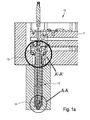
- Fig. 1a shows a hot runner system 10, a valve gated nozzle 12 and an improved nozzle heater 14 according to an exemplary embodiment of the invention.
- A'-A' indicates the potential heat loss at the head portion of the nozzle due to contact with colder parts adjacent the manifold, such as mold plate 13.
- A-A indicates the potential heat loss at the tip portion of the nozzle due to contact with other colder parts.
- This A-A area is also close to a gate area of a mold cavity (not shown) where access of a molten material delivered through a manifold 11 and nozzle 12 is controlled by the movement of valve pin 28.
- Fig. 1b shows the hot runner system 10 and an open gate nozzle 16 and the nozzle heater 14 according to an exemplary embodiment of the invention where the area B'-B' indicates the potential heat loss at the head portion of the nozzle due to contact with colder parts. Also as known area B-B indicates the potential heat loss at the tip portion of the nozzle due to contact with other colder parts. This B-B area is also close to a gate area of a mold cavity (not shown) where access of a molten material delivered through a manifold 11 and nozzle 12 is controlled by the cooling channels 15. In the embodiment of Fig.
- thermocouple 17 or similar temperature sensor is coupled to the manifold to measure the temperature of a molten material as it exits the manifold and enters the nozzle melt channel. This helps to fine tune the heating power of the nozzle heater considering that this is an open gate design that is harder to control at the gate.
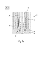
- Fig. 2a shows tip portion 18 of the valve gated nozzle 12 and a nozzle heater 14 according to an exemplary embodiment of the invention.
- nozzle tip portion 18 shown in circle A-A in Fig. 1a there is a heat loss caused by the contact between a seal 20 of the nozzle tip 22 and the wall 24 of a mold plate 26.
- the heat loss creates an undesirable heat profile along the nozzle and may also create in time an accumulation of cold residual material and wear of the valve pin 28.
- Fig. 2b shows a tip portion 19 of the open gate nozzle 16 (also known as a thermal gate) and a nozzle heater 14 according to an exemplary embodiment of the invention.
- the nozzle tip portion 19 shown in circle B-B in Fig. 1b there is a heat loss caused by the contact between an insulation seal 20 of the nozzle tip 22 and the wall 24 of a mold plate 26.
- the heat loss creates an undesirable heat profile along the nozzle and may also create in time an accumulation of residual material or stringing of material.
- Fig. 2c shows the enlarged portion A'-A' of Fig. 1 and the area of potential heat loss at the head portion 21 of the nozzle 12 due to contact with colder mold plate 13.
- heater 14 is provided according to this invention with a segmented support sleeve and a single heater element coupled to the segmented support sleeve. Exemplary embodiments are shown in various design options in Figs. 4 -9 .
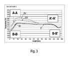
- Fig. 3 shows just an example of the heat profile along a nozzle such as valve gated nozzle 12 or an open gate nozzle 16 using a nozzle heater 14 in its design variations according to exemplary embodiments of Figs. 4-9 of the invention.
- portions I show the heat profile at the tip area of the same heater for two nozzle styles, the valve gate A-A and A'-A' and the open gate B-B'.
- the graph shows a bigger heat loss at the tip that is compensated by adding more heater element wattage at the tip or improving the clamp force at the tip.
- Graphs II, III, IV show changes in the heat profile at the nozzle tip portions by variations of the wattage of the heater and changes in the clamp force.
- Figs. 4a-4d , Figs. 5a-5c , Figs. 6a-6c and Figs. 7a-7b show various embodiments of a nozzle heater 14 shown in Figs. 1 and 2 as being coupled to nozzle 12 and nozzle 16.
- Figs. 4 to 6 show an embodiment where a single piece support sleeve 30 or 30' and a heating element 32 or 32' coupled to the support 30-30' are twisted in the form of a helical tube that has several axial gaps 33 or 33' between consecutive sleeve segments 35-36-37 or 35'-36'-37'.
- the gaps and the segments are designed to allow the heater to have a self-clamping force feature when it slides onto the body of a nozzle and is secured onto the nozzle body and then fixed into a permanent operating position.
- the heater can be removed from the nozzle body very easy as the inner diameter of the helical tube is slightly enlarged.
- the heater tube will have a slightly reduced inner diameter and that will increase the clamping force.
- the support sleeve 30 allows for a better heat distribution form the heating element 32 to the nozzle body, compared to a situation where the heating element 32 is coupled directly to the nozzle body, as known in the art.
- the helical tube support 30 is in a stretched position that generates the clamp force that can be slightly changed via more or less axial expansion/stretching.
- the heater support sleeve 30' is shown in a compressed situation that reduces gap 33' and allows for an easier removal of the heater off the nozzle.
- the nozzle sleeve 30 and a nozzle heater element 32 are thus forming a heater assembly 34 according to a first embodiment.
- a first manufacturing step of the heater assembly 34 is shown.
- a flat or planar or sheet like heater element support 30 is first selected and prepared of a thermally conductive material that can be coiled or turned into a helical tube like sleeve without damaging its mechanical properties.
- a heater element 32 including an insulating cover is coupled, connected or attached to the support 30 using known methods such as welding or bonding.
- a heater element 32' can be attached via pressing into a helical groove made on the support 30' and shown in more detail in Figs. 7a-b . In this case the heater element 32 and the heater support 30 form the novel nozzle heater 34.
- the flat or planar or sheet like heater element support 30 can be composed of multiple materials, in Fig. 4d exemplary two layers are shown.
- a first material 30a is copper and a second material 30b is steel.
- a heater element 32 is embedded in a groove within the copper layer for increasing the heat transfer between the heater element 32 and the heater sleeve or tube 30.
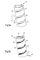
- the support 30 can be coiled in cold or warm conditions having the heater element either on the interior or the exterior side of the support as seen in Fig. 5a . If the heater element is on the inner side it may make a better contact with a nozzle body. The heat profile and heat transfer is also good when the heater element 32 is positioned on the outer surface of the support 30, as shown in Figs 6a-6c .
- heater element support 30 is coiled, several heater elements segments 35-36-37 can be defined along an axis of the nozzle heater 34 and along the hot runner nozzle 12 shown in Fig 6c .
- the heater element support 30 is coiled it can be manufactured easier than by turning from a bar and there is no need for tight tolerances between the inner diameter of the coiled heater and the outer diameter of the nozzle. Furthermore, the coiled or helical shape allows for a better clamping of the heater element 34 onto the nozzle 40. Also, the helical structure and the sleeve segments defined by the helical shape allows these segments to be axially moved along the nozzle to locate each segment in a desired position along the nozzle.
- the coiled or helical sleeve that also forms a tube can have a spacing between each segment that can be increased or reduced as indicated by the arrows.
- the clamping force is bigger when the helical sleeve is in the extended position of Fig. 5a and the clamping force is smaller when the helical sleeve is collapsed as shown in Fig. 5c and this reduces the heat transfer.
- the helical sleeve can also include slots or openings in the middle section to reduce the heat transfer in the middle section of the nozzles and improve the heat profile as shown in the chart of Fig. 3 .
- the heater shown in Figs. 4a-4d can have a heater element designed to have more wirings and thus more power and heat at the ends of the heater.
- a thermocouple element 31 is shown as being located on the spiral created by the helical support sleeve having a measurement head located at one end of the support.
- the coiled or helical sleeve 30' includes a helical groove 44 or grooves.
- a heater element 32' is pressed into the grooves 44.
- gaps 33' are minimum to allow the heater 34' be removed or coupled to the nozzle body.
- Heater sleeve 60 or 60' is made of several sleeve segments, such as for example five segments 61, 63, 65, 67, 69 that define a the modular heater element sleeve 60.
- the segments 61, 63, 65, 67, 69 can be relatively moved axially relative to each other before installing them along the nozzle body 34 of nozzle 12 shown in Fig. 6c to provide a desired heat profile and to accommodate a range of nozzle lengths.
- segments 61 and 63 of Fig. 8a can be made of the same high thermally conductive material including Copper, Beryllium Copper, Aluminum and known alloys of these materials. These ensure that areas of the nozzles in Figs 1a and 1b that have a higher heat loss get more heat energy from the heater sleeve 60 or 60'.
- the heater segments for example 65, 67, 69 can be made of less thermally conductive materials such as H13 metals.
- These intermediate segments 65, 67, 69 can also be made of thermally insulative material such as ceramics of various properties.
- the end segments 61 and 63 include helical groves 55a and 55b that are used to receive a single heater element 32 pressed into the helical grooves.
- the heater element 32 is also pressed into a longitudinal groove 53 consisting of groove segments 53a, 53b, 53c.
- This intermediate portion of the heater element has a minimum length in the segments 65, 67 and 69 to reduce the amount of heat in these middle sections of the nozzle heater.
- a longitudinal slot 51 formed of segment slots 51a, 51b, 51c, 51d and 51e is machined to create a slightly flexible sleeve to facilitate the removal of each segment from the nozzle.
- Transversal gaps 54a, 54b, 54c and 54d that are perpendicular to an axis of the sleeve 60' define a space between these segments and they have both a manufacturing function and an operational-performance function. These gaps can have a minimum size where the heater segments touch or almost touch each other or they may be formed to create distances that allow the segments to be more spread and cover nozzles of various lengths and/ or interrupt the heat transfer from segment to segment.
- Fig. 8c shows additional elongated grooves 59a, 59b and 59c being formed in the middle sections.
- the heater element 32 has a resistance wire 50 enclosed in a refractory powder electrical insulating material 49 such as magnesium oxide powder in an outer steel casing 48.
- the resistance wire 50 has a helical path that allows for a longer element to be enclosed in the steel casing 48 to provide a higher heating power.
- Heating element 32 is press fitted into helical grooves 55a, 55b located on an outer surface of the first support segment 61 and of second support segment 63.
- An intermediate portion of the heater element 32 is also pressed into a longitudinal groove 53 consisting of several groove segments 53a, 53b, 53c. By doing this, the heating element is fully secured to the sleeve 60' in a good thermal contact position.
- two branches 32a and 32b of the heater element 32 are created by using a U-shaped heating element and this allows to bring terminals + and - at the end portion 61 of heater assembly 60 and heater sleeve 60'.
- the first branch 32a is pressed in grooves 53a, 53b, 53c and the second branch 32b is placed on corresponding grooves 53a, 53b, 53c situated on the other side of heater assembly 60 and heater sleeve 60' (not shown).
- Figs. 9a-9d show a nozzle sleeve and a nozzle heater assembly 80 according to another exemplary embodiment of the invention.
- the heater sleeve or tube 80'' is made of two semicircular or semi cylindrical segments 85a and 85b that together form an enclosed circular or cylindrical element 80 when placed on the nozzle shown in Figs 1 and 2 .
- a heater element 95 connects the two segments to secure and clamp the heater onto the nozzle.
- the semi cylindrical segments can be made by cutting a cylinder along its axis or by bending two flat surfaces. Each segment includes upper and lower helical grooves 87a and 89a that are matched with corresponding helical grooves 87b and 89b on the other segment that completes the heater assembly 80. These segments are separated by a gap 91 that becomes two longitudinal slots 91 when the two semi-cylindrical segments 85a and 85b are coupled using heater element 95.
- the heater sleeve or tube 80' is similar with the heater sleeve 80, 80'' shown in Fig. 9b and 9c but it is made of several sleeves or tubes that are each made of two semi-cylindrical sub-segments (as mentioned in the previous paragraph) and they are all secured as a heater element by an external heater element that helps to create a clamp force onto the nozzle heater.
- This embodiment of Fig. 9a is the semi-cylindrical version of Fig. 8 a.
- a thermocouple TC is located in either gap 91 or 93 shown in Fig. 9c .
- thermocouples can be used in gaps 91, 93 as a backup or two measure the temperatures at two different locations along the heater sleeve and nozzle.
- the gap 93 shown in Fig. 9c can also be designed as a groove 93 for accommodating a thermocouple 93.
- the heater sleeve 80" shown in Fig. 9b-9c is further segmented in the middle via transversal gaps.
- a middle or intermediate sleeve made of two semi cylindrical segments 84a-84b is added between segments (81a-81b and 86a-86b).
- This design is similar to the design shown in the embodiments of Fig. 8a-8i , except that each segment shown in Figs. 8a-8i are split to create a semi-cylindrical half.
- the embodiments of Figs. 9 are easier and faster to produce and the heater element 95 is used to secure and provide a clamp force of the heater to the nozzle.
- the semicircular or semi-cylindrical segments 85a and 85b of the heater sleeve 80" and the segments 82a-b, 84a-b and 86a-b of the heater sleeve 80' are manufactured according to an exemplary embodiment of the invention from a flat or planar sheet.
- the planar sheet is next deformed in a press that creates the semi-circular or semi-cylindrical segments 85a and 85b of the heater sleeve 80" and the segments 82a-b 84a-b and 86a-b of the heater sleeve 80' that will match the outer surface diameter of a nozzle.
- the grooves 81 and 83 are further formed via a subsequent or simultaneous stamping process using a profiled stamper replicating the grooves. This step of forming the grooves via a deformation process can take place before or after or simultaneous to the stamping process that creates the semicircular or semi-cylindrical shape of each segment.
- a production line can be set where a large sheet is first divided into multiple flat elements, the flat elements are next collected and placed into a stamper in batches, and in the next step each batch of flat elements is automatically semi-cylindrical shaped and profiled with the required grooves.
- the support segments are coupled or connected using the heater element 95 shown in Figs 9c and 9d .
- This is done using a special jig that simulates the nozzle body in terms of the required inner diameter of the heater assembly 80 or 80' or 80" to match each nozzle.
- the length of the heater element 95 is calculated in such a way to provide the required amount of heat and also to contribute to the creation of the clamping force needed to secure the heater to the nozzle in a perfect thermal contact.
- the heater element is pressed into the grooves to ensure an optimum heat transfer into the segments.
- the heater element is subsequently swaged into the grooves to further improve the heat transfer and also better secure the heating element.
- a thin cylindrical cover made of either a thermally conductive material or more insulative material is placed over the two segments and then swaged over the heater element and onto the grooves.
- the semicircular or semi-cylindrical segments 85a and 85b of the heater sleeve 80" and the segments 82a, 82b; 84a 84b and 86a, 86b are manufactured according to another exemplary embodiment of the invention by using an injection molding process or a dye casting process using a mold or a dye.
- each segment 85a and 85b of the heater sleeve 80" and the segments 82a, 82b; 84a 84b and 86a, 86b of heater sleeve 80' are semicircular and the corresponding grooves 81a-81b and 83a-83b are part of them
- the segments can be molded or dye cast by creating in a single step both the curved surfaces and the grooves without the need or fear to have to deal with undercuts that make impossible the removal of the segments after molding from the mold or dye.
- the segments can be molded out of high thermally conductive materials such as aluminum and aluminum based materials or ceramics that can be either thermally conductive or thermally insulative.
- the heater element is made of at least two segments that are separated by an axial or longitudinal gap. In all of these embodiments there is a single heating element that is coupled and secured to each segment to form a single unit heater.
Landscapes
- Engineering & Computer Science (AREA)
- Manufacturing & Machinery (AREA)
- Mechanical Engineering (AREA)
- Chemical & Material Sciences (AREA)
- Ceramic Engineering (AREA)
- Injection Moulding Of Plastics Or The Like (AREA)
- Moulds For Moulding Plastics Or The Like (AREA)
Description
- This invention is related to an injection molding apparatus. More particularly this invention is related to a nozzle heater assembly and to a method of manufacturing a nozzle heater assembly.
- Heaters for hot runner nozzles are known. In some applications the nozzle heater is embedded in the nozzle body or attached to the nozzle body. In other applications the nozzle heater is composed of a support element such as a sleeve or a tube and a heating element is coupled, for example secured to the inside or outside of the sleeve or tube.
- When the hot runner nozzle is placed in a hot runner system, the nozzle and components of the nozzle make direct contact with parts of the hot runner system and parts of the mold that are colder than the nozzle and parts associated with the hot runner nozzle. These contacts cause a heat loss and this creates a non-uniform heat profile along the nozzle.
There is a need to further improve the heaters used for injection molding hot runners and meet specific challenges such as mentioned bellow. - The heat profile can be improved by a better design of the heater and also by providing a better clamping/ connection of the nozzle heater to the nozzle.
- Also the heater design may need to take into consideration the heating requirements for several applications and for several dimensions of the nozzle.
- If a nozzle heater fails or its performance is not acceptable there is a need to replace the heater with minimum effort and in a record time from the front of the nozzle.
- All of these also requires that the heater should be easier to manufacture and within acceptable tolerances.
- There is also a need to develop a manufacturing process for nozzle heater assemblies that use less raw materials and simpler and fewer manufacturing steps that all together reduce the energy consumption significantly.
- A solution for the above indicated objectives is given by the teaching of the independent claims. Further embodiments of the invention are subject of the dependent claims.
- A nozzle heater assembly for hot runner nozzles according to this invention is composed of a single heating element and several sections or segments that together form a heater sleeve or tube. The heating element is coupled to the segmented heater sleeve.
- In a first embodiment a nozzle heater assembly to be coupled to a hot runner nozzle, comprises a heater support made of at least two adjacent support segments spaced apart by at least one first gap and a heater element secured to the at least two support segments whereby the heater element is configured to limit the at least one first gap between the at least two segments and whereby the heater element makes indirect contact with the hot runner nozzle via nozzle sleeve segments.
- In a further embodiment a nozzle heater assembly to be coupled to a hot runner nozzle comprises a heater support formed of a single piece, the heater support being configured as a hollow helical tube including at least two axial gaps and a heater element secured to the helical tube, whereby the helical tube can be axially compressed or stretched to alter a clamping force generated when the helical tube and the heater are coupled to the hot runner nozzle.
- In particular, the heater sleeve or tube is made of a single support element and the single support element is shaped as a coil or a helical tube that is able to surround the nozzle body from a tip portion up to a head portion of the nozzle. In this design the axial gaps or the axial separations between the portions of the coiled or helical sleeve or tube create a multi-segment heater sleeve. The sleeve segments are configured to be movable axially relative to each other when the heater sleeve is arranged/ coupled to the nozzle body. This allows for an easier installation of the nozzle heater onto the nozzle body. This further allows for an easier manufacturing and servicing of the nozzle. Furthermore, this allows for a better clamping and heat transfer from the nozzle heater to the nozzle body.
- In one embodiment a heater element is attached to the inner surface of the helical or coiled sleeve.
- In another embodiment the heater element is attached to the outer surface of the helical or coiled sleeve. Here, the heater element goes fully around and is helical over the full diameter of the nozzle and goes over the gaps of the segments or the gaps between the heater segments, in particular over longitudinal or transversal gaps.
- In the above mentioned embodiments the sleeve segments may be fully enclosed cylindrical elements or they may include an in particular end-to-end axial elongated slot or gap that creates an open cylindrical element. Such a slot or gap creates a flexible sleeve segmented that can be easier attached or removed from the nozzle for installation and service requirements. Furthermore the slot or gap allows the heater sleeves to be clamped and generate a clamp force in both cold (i.e. room temperature), or hot (operation) conditions.
- In another embodiment a heater assembly to be coupled to a hot runner nozzle comprises a heater support made of a first support segment and a second support segment, the second support segment is arranged adjacent and spaced apart by a first gap with respect to the first support segment and a heater element secured to the first support segment and secured to the second support segment whereby the heater element is configured to mechanically connect the first support segment and the second support segment and whereby the heater element makes indirect contact with the hot runner nozzle.
- In a further embodiment a nozzle heater assembly to be coupled to a hot runner nozzle comprises a heater support made of at least two adjacent support segments spaced apart by at least one first gap and a heater element secured to the at least two support segments whereby the heater element is configured to limit the at least one first gap between the at least two segments and whereby the heater element makes indirect contact with the hot runner nozzle.
- The heater element is attached to the heater segments in a way that the heat from the heater element is transferred only via the segments to the nozzle. Thus, the heater element only makes indirect contact with the hot runner nozzle. The advantage of this design is that the heat will be distributed within the segments before it is transferred to the surface of the nozzle and thus result in a more balanced distribution of the transferred heat.
- In a preferred embodiment a least one third support segment is located between the first support segment and the second support segment, wherein the third support segment is retaining a portion of the heater element.
- In a further preferred embodiment the first gap between the first support segment or the second support segment and a third support segment is parallel to at least one second gap between the first support segment or the second support segment and a third support segment or parallel to at least one second gap between two third support segments.
- In a further preferred embodiment, at least one support segment is made up of two semi-cylindrical elements that form a cylindrical support segment.
- In a further preferred embodiment, the first semi-cylindrical element and the second semi-cylindrical element together form a cylindrical support segment when they are mechanically connected via the heater element.
- In particular, the heater sleeve or tube is made of several sleeves or tubes and a single heater element is attached or coupled to each and all of these sleeves. These sleeves form heater sleeve segments that are configured to be made of the same material or different materials. These materials have different thermal conductivities and the selection of material will impact the heat profile of the heater. The segments may have the same length, different lengths, same thickness or different thicknesses. Also it is possible that from one nozzle to the next used in the same hot runner system, each segment to be different with respect to a segment from the other nozzle. The segments may have also different other features that are used to either reduce or increase the amount of heat transferred from the heater to the nozzle body and to the melt flowing through the nozzle. The segments of each heater are in some instances movable axially relative to each other when the heater sleeve is arranged/ coupled to the nozzle body in order to accommodate nozzles of different lengths. Furthermore some segments can be stored as standard components and used in conjunction with other segments that are adapted in function to some customized requests.
- In another embodiment of the nozzle heater assembly the heater sleeve or tube is made of two semicircular or semi cylindrical segments that together form an enclosed circular or cylindrical element when placed on the nozzle and a heater element connects the two segments to secure and clamp the heater onto the nozzle. The semi cylindrical segments can be made by cutting a cylinder along its axis or by bending a flat surface.
- In another embodiment of the nozzle heater assembly the heater sleeve or tube is made of several sleeves or tubes that are each made of two semi-cylindrical sub-segments (as mentioned in the previous paragraph) and they are all secured as a heater element by an external heater element that helps to create a clamp force onto the nozzle heater.
- In another embodiment of the nozzle heater assembly the heater element is U-shaped. In particular, the heater element is U-shaped and includes two heater branches embedded in longitudinal grooves.
- In another embodiment of the nozzle heater assembly the gaps between the segments are arranged transversal and/ or the gaps between the segments are arranged longitudinal.
- In another embodiment of the nozzle heater assembly the segments are made of different materials and/ or are made of materials having a different thermal conductivity.
- In another embodiment of the nozzle heater assembly the heater element goes fully around and is helical over the full diameter of the heater support and crosses the longitudinal grooves.
- In all the above mentioned heater styles or designs, the heater sleeve or tube is made of at least two segments that are separated by an axial or longitudinal gap, even though they can be made of one single piece and formed accordingly. In particular the manufacture of such heater sleeves uses less raw materials and simpler and fewer manufacturing steps are required, which reduces the energy consumption for manufacturing significantly. In all of these embodiments there is a single heater element that is coupled and secured to each segment to form a single heater unit when attached to the nozzle body. In particular, the heater element goes fully around and is helical over the full diameter of the nozzle and goes over the gaps of the segments or the gaps between the heater segments, in particular over longitudinal or transversal gaps. The heater element is attached to the heater sleeve or tube in such a manner, that when mounting the nozzle heater assembly to the nozzle, the heating element limits at least one gap of a support segment or between adjacent support segments. Thereby the inner diameter of the segment(s) is reduced which results in a better clamping and connection between the nozzle heater assembly and the nozzle. This design is also advantageous for the disassembly of the nozzle heater from the nozzle: by removing the heater element from the heater sleeve or tube, the narrowed gaps expand and facilitate the removal of the sleeve or tube from the nozzle.
- A solution for above indicated objectives is also given by the inventive methods of manufacturing a nozzle heater assembly. Further embodiments of the methods are subject of the dependent claims.
- A first method of manufacturing a nozzle heater assembly for an injection molding nozzle comprises the following steps:
- providing two flat substrates;
- stamping the two substrates to form two semi-cylindrical components or segments of equal curvature, wherein each segment has an inner surface and an outer surface;
- forming a series of grooves on the outer surface of the two semi-cylindrical components or segments;
- placing the two semi-cylindrical components or segments side by side with the inner surfaces facing each other;
- pressing a heater element into the grooves to secure the two segments as a single unit and provide two longitudinal gaps between the two segments.
- A preferred embodiment of the above method further comprises the step of swaging the heater element onto the grooves, a further preferred embodiment of the method further comprises the step of providing a cylindrical cover over the two segments and swaging the cylindrical cover over the heater element onto the grooves.
- A second method of manufacturing a nozzle heater assembly for an injection molding nozzle comprises the following steps:
- providing a mold or a dye having a mold or a dye cavity;
- feeding a molten material into the mold or dye cavity to form a semi-cylindrical heater segment having a curved inner surface and a curved outer surface, the outer surface including a profiled groove;
- cooling the molten material in the mold or dye;
- extracting a solidified segment from the mold;
- placing the two semi-cylindrical components or segments side by side with the inner surfaces facing each other;
- pressing a heater element into the grooves to secure the two segments as a single unit and to provide two longitudinal gaps between the two segments.
- Preferred embodiments of the above methods further comprises the step of swaging the heater element onto the grooves, a further preferred embodiment of the methods further comprises the step of providing a cylindrical cover over the two segments and swaging the cylindrical cover over the heater element onto the grooves.
- Further advantages, features and possible applications of the present invention ensue from the following description in conjunction with the figures.
- Fig. 1a
- shows a cross section through an exemplary hot runner system including a valve gated nozzle and a nozzle heater according to an exemplary embodiment of the invention.
- Fig. 1b
- shows a cross section through an exemplary hot runner system including an open gate nozzle and a nozzle heater according to an exemplary embodiment of the invention.
- Fig. 2a
- shows a cross section through a tip portion of a valve gated nozzle shown in
Fig. 1a . - Fig. 2b
- shows a cross section through a tip portion of an open gate nozzle shown in
Fig. 1b . - Fig. 2c
- shows a cross section through a head portion of the nozzle shown in
Fig. 1a . - Fig. 3
- shows heat profiles along an exemplary hot runner nozzle.
- Figs. 4a-4d
- show various stages of a making nozzle sleeve and a nozzle heater according to an exemplary embodiment of the invention.
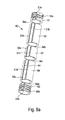
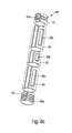
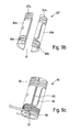
- Figs. 5a-5c
- show various stages of a nozzle sleeve, a nozzle heater and a nozzle thermocouple according to the embodiment of
Figs. 4a-b-c-d . - Figs. 6a-6c
- show a nozzle, a nozzle heater and a nozzle thermocouple according to an exemplary embodiment of the invention and in relation to
Figs. 4-5-6 . - Figs. 7a-7b
- show a nozzle sleeve and a nozzle heater according to an exemplary embodiment of the invention and in relation to
Figs. 4-5-6 . - Fig. 8a-81
- show a nozzle sleeve and a nozzle heater according to another exemplary embodiment of the invention.
- Figs. 9a-9f
- show a nozzle sleeve and a nozzle heater according to another exemplary embodiment of the invention.
-
Fig. 1a shows ahot runner system 10, a valvegated nozzle 12 and animproved nozzle heater 14 according to an exemplary embodiment of the invention. As known area A'-A' indicates the potential heat loss at the head portion of the nozzle due to contact with colder parts adjacent the manifold, such asmold plate 13. Also as known area A-A indicates the potential heat loss at the tip portion of the nozzle due to contact with other colder parts. This A-A area is also close to a gate area of a mold cavity (not shown) where access of a molten material delivered through a manifold 11 andnozzle 12 is controlled by the movement ofvalve pin 28. -
Fig. 1b shows thehot runner system 10 and anopen gate nozzle 16 and thenozzle heater 14 according to an exemplary embodiment of the invention where the area B'-B' indicates the potential heat loss at the head portion of the nozzle due to contact with colder parts. Also as known area B-B indicates the potential heat loss at the tip portion of the nozzle due to contact with other colder parts. This B-B area is also close to a gate area of a mold cavity (not shown) where access of a molten material delivered through a manifold 11 andnozzle 12 is controlled by the coolingchannels 15. In the embodiment ofFig. 1b athermocouple 17 or similar temperature sensor is coupled to the manifold to measure the temperature of a molten material as it exits the manifold and enters the nozzle melt channel.
This helps to fine tune the heating power of the nozzle heater considering that this is an open gate design that is harder to control at the gate. -
Fig. 2a showstip portion 18 of the valvegated nozzle 12 and anozzle heater 14 according to an exemplary embodiment of the invention. In thenozzle tip portion 18 shown in circle A-A inFig. 1a , there is a heat loss caused by the contact between aseal 20 of thenozzle tip 22 and thewall 24 of amold plate 26. The heat loss creates an undesirable heat profile along the nozzle and may also create in time an accumulation of cold residual material and wear of thevalve pin 28. -
Fig. 2b shows atip portion 19 of the open gate nozzle 16 (also known as a thermal gate) and anozzle heater 14 according to an exemplary embodiment of the invention. In thenozzle tip portion 19 shown in circle B-B inFig. 1b , there is a heat loss caused by the contact between aninsulation seal 20 of thenozzle tip 22 and thewall 24 of amold plate 26. The heat loss creates an undesirable heat profile along the nozzle and may also create in time an accumulation of residual material or stringing of material. -
Fig. 2c shows the enlarged portion A'-A' ofFig. 1 and the area of potential heat loss at thehead portion 21 of thenozzle 12 due to contact withcolder mold plate 13. - In order to improve the heat profile of valve gated
hot runner nozzle 12 or a thermal gate oropen gate nozzle 16,heater 14 is provided according to this invention with a segmented support sleeve and a single heater element coupled to the segmented support sleeve. Exemplary embodiments are shown in various design options inFigs. 4 -9 . -
Fig. 3 shows just an example of the heat profile along a nozzle such as valvegated nozzle 12 or anopen gate nozzle 16 using anozzle heater 14 in its design variations according to exemplary embodiments ofFigs. 4-9 of the invention. In the first graph, portions I show the heat profile at the tip area of the same heater for two nozzle styles, the valve gate A-A and A'-A' and the open gate B-B'. The graph shows a bigger heat loss at the tip that is compensated by adding more heater element wattage at the tip or improving the clamp force at the tip. Graphs II, III, IV show changes in the heat profile at the nozzle tip portions by variations of the wattage of the heater and changes in the clamp force. -
Figs. 4a-4d ,Figs. 5a-5c ,Figs. 6a-6c andFigs. 7a-7b show various embodiments of anozzle heater 14 shown inFigs. 1 and2 as being coupled tonozzle 12 andnozzle 16. -
Figs. 4 to 6 show an embodiment where a singlepiece support sleeve 30 or 30' and aheating element 32 or 32' coupled to the support 30-30' are twisted in the form of a helical tube that has severalaxial gaps gaps 33 in particularly through an axial movement of the segments, the heater can be removed from the nozzle body very easy as the inner diameter of the helical tube is slightly enlarged. On the other hand by increasing the gaps, or by stretching the helical tube, the heater tube will have a slightly reduced inner diameter and that will increase the clamping force. Thesupport sleeve 30 allows for a better heat distribution form theheating element 32 to the nozzle body, compared to a situation where theheating element 32 is coupled directly to the nozzle body, as known in the art. InFigs. 5a-5c thehelical tube support 30 is in a stretched position that generates the clamp force that can be slightly changed via more or less axial expansion/stretching. InFig 5c the heater support sleeve 30' is shown in a compressed situation that reducesgap 33' and allows for an easier removal of the heater off the nozzle. - The
nozzle sleeve 30 and anozzle heater element 32 are thus forming aheater assembly 34 according to a first embodiment. - In
Fig. 4a a first manufacturing step of theheater assembly 34 is shown. A flat or planar or sheet likeheater element support 30 is first selected and prepared of a thermally conductive material that can be coiled or turned into a helical tube like sleeve without damaging its mechanical properties. Aheater element 32 including an insulating cover is coupled, connected or attached to thesupport 30 using known methods such as welding or bonding. Also a heater element 32' can be attached via pressing into a helical groove made on the support 30' and shown in more detail inFigs. 7a-b . In this case theheater element 32 and theheater support 30 form thenovel nozzle heater 34. - As shown in
Fig. 4d , the flat or planar or sheet likeheater element support 30 can be composed of multiple materials, inFig. 4d exemplary two layers are shown. In this exemplary embodiment, afirst material 30a is copper and asecond material 30b is steel. As the thermal expansion of copper is higher than the thermal expansion of steel, the connection between the heater tube or sleeve and the hot runner nozzle will not be affected with increasing temperature during operation of the injection molding machine. Aheater element 32 is embedded in a groove within the copper layer for increasing the heat transfer between theheater element 32 and the heater sleeve ortube 30. - As shown in
Figs. 5a-5c thesupport 30 can be coiled in cold or warm conditions having the heater element either on the interior or the exterior side of the support as seen inFig. 5a . If the heater element is on the inner side it may make a better contact with a nozzle body. The heat profile and heat transfer is also good when theheater element 32 is positioned on the outer surface of thesupport 30, as shown inFigs 6a-6c . - Because the
heater element support 30 is coiled, several heater elements segments 35-36-37 can be defined along an axis of thenozzle heater 34 and along thehot runner nozzle 12 shown inFig 6c . - Because the
heater element support 30 is coiled it can be manufactured easier than by turning from a bar and there is no need for tight tolerances between the inner diameter of the coiled heater and the outer diameter of the nozzle. Furthermore, the coiled or helical shape allows for a better clamping of theheater element 34 onto thenozzle 40. Also, the helical structure and the sleeve segments defined by the helical shape allows these segments to be axially moved along the nozzle to locate each segment in a desired position along the nozzle. - As shown in
Fig. 5a-5c , the coiled or helical sleeve that also forms a tube, can have a spacing between each segment that can be increased or reduced as indicated by the arrows. The clamping force is bigger when the helical sleeve is in the extended position ofFig. 5a and the clamping force is smaller when the helical sleeve is collapsed as shown inFig. 5c and this reduces the heat transfer. The helical sleeve can also include slots or openings in the middle section to reduce the heat transfer in the middle section of the nozzles and improve the heat profile as shown in the chart ofFig. 3 . In order to further or separately improve the heat profile along the nozzle and increase the heat transfer at the ends of the nozzle, at the tip portion and or the head portion, the heater shown inFigs. 4a-4d can have a heater element designed to have more wirings and thus more power and heat at the ends of the heater. InFig. 5b athermocouple element 31 is shown as being located on the spiral created by the helical support sleeve having a measurement head located at one end of the support. - In another exemplary embodiment of the invention shown in
Figs. 7a-7b , the coiled or helical sleeve 30' includes ahelical groove 44 or grooves. InFig. 7a , there is no heater element in thegroove 44, inFig. 7b a heater element 32' is pressed into thegrooves 44. In theseembodiments gaps 33' are minimum to allow the heater 34' be removed or coupled to the nozzle body. - In the embodiment of
Figs. 8a-8c another style or design of a multisegment heater sleeve 60 and 60' is shown, to be used for examples withhot runner nozzles Heater sleeve 60 or 60' is made of several sleeve segments, such as for example fivesegments heater element sleeve 60. Thesegments nozzle body 34 ofnozzle 12 shown inFig. 6c to provide a desired heat profile and to accommodate a range of nozzle lengths. Thesesegments Fig. 8a can be made of different materials having different thermal conductivities, a different length and for some applications having a different thickness. Forexample segments Fig. 8a can be made of the same high thermally conductive material including Copper, Beryllium Copper, Aluminum and known alloys of these materials. These ensure that areas of the nozzles inFigs 1a and1b that have a higher heat loss get more heat energy from theheater sleeve 60 or 60'. In these embodiments the heater segments for example 65, 67, 69 can be made of less thermally conductive materials such as H13 metals. Theseintermediate segments Fig. 8 , theend segments helical groves single heater element 32 pressed into the helical grooves. - The
heater element 32 is also pressed into alongitudinal groove 53 consisting ofgroove segments segments longitudinal slot 51 formed ofsegment slots Transversal gaps - In another exemplary embodiment of the invention, not shown, only three segments such as for
example segments middle segment 67 being similar to themiddle segment 67 shown inFigs. 8a-8c . To further reduce the heat transfer,Fig. 8c shows additionalelongated grooves - As further seen in
Figs. 8d-8i theheater element 32 has aresistance wire 50 enclosed in a refractory powder electrical insulatingmaterial 49 such as magnesium oxide powder in anouter steel casing 48. Theresistance wire 50 has a helical path that allows for a longer element to be enclosed in thesteel casing 48 to provide a higher heating power.Heating element 32 is press fitted intohelical grooves first support segment 61 and ofsecond support segment 63. An intermediate portion of theheater element 32 is also pressed into alongitudinal groove 53 consisting ofseveral groove segments - As shown in
Fig. 8d twobranches heater element 32 are created by using a U-shaped heating element and this allows to bring terminals + and - at theend portion 61 ofheater assembly 60 and heater sleeve 60'. Thefirst branch 32a is pressed ingrooves second branch 32b is placed on correspondinggrooves heater assembly 60 and heater sleeve 60' (not shown). - Placing only two
straight branches heater 32 in the middle section that are also embedded in grooves provides both mechanical stability and a limited heat transfer that is less than inextreme sections segment bodies branches heater element branches nozzle body 34 shown inFig. 8i . -
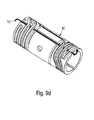
Figs. 9a-9d show a nozzle sleeve and anozzle heater assembly 80 according to another exemplary embodiment of the invention. - In the exemplary embodiments of the invention shown in
Figs. 9b and 9c , the heater sleeve or tube 80'' is made of two semicircular or semicylindrical segments cylindrical element 80 when placed on the nozzle shown inFigs 1 and2 . Aheater element 95 connects the two segments to secure and clamp the heater onto the nozzle. The semi cylindrical segments can be made by cutting a cylinder along its axis or by bending two flat surfaces. Each segment includes upper and lowerhelical grooves helical grooves heater assembly 80. These segments are separated by agap 91 that becomes twolongitudinal slots 91 when the twosemi-cylindrical segments heater element 95. - In another exemplary embodiment of the invention shown in
Fig. 9a , the heater sleeve or tube 80' is similar with theheater sleeve 80, 80'' shown inFig. 9b and 9c but it is made of several sleeves or tubes that are each made of two semi-cylindrical sub-segments (as mentioned in the previous paragraph) and they are all secured as a heater element by an external heater element that helps to create a clamp force onto the nozzle heater. This embodiment ofFig. 9a is the semi-cylindrical version ofFig. 8 a. As shown inFig. 9d , a thermocouple TC is located in eithergap Fig. 9c . In some embodiments two thermocouples can be used ingaps gap 93 shown inFig. 9c can also be designed as agroove 93 for accommodating athermocouple 93. - In the embodiment of
Fig. 9a theheater sleeve 80" shown inFig. 9b-9c is further segmented in the middle via transversal gaps. A middle or intermediate sleeve made of two semicylindrical segments 84a-84b is added between segments (81a-81b and 86a-86b). This allows the intermediate sleeves to be made of a different material (usually less thermally conductive). This design is similar to the design shown in the embodiments ofFig. 8a-8i , except that each segment shown inFigs. 8a-8i are split to create a semi-cylindrical half. The embodiments ofFigs. 9 are easier and faster to produce and theheater element 95 is used to secure and provide a clamp force of the heater to the nozzle. - In the exemplary embodiments of the invention shown in
Figs. 9a to 9f the semicircular orsemi-cylindrical segments heater sleeve 80" and thesegments 82a-b, 84a-b and 86a-b of the heater sleeve 80' are manufactured according to an exemplary embodiment of the invention from a flat or planar sheet. - For example once the flat or planar sheet is selected and cut to the right dimension via a stamping process, the planar sheet is next deformed in a press that creates the semi-circular or
semi-cylindrical segments heater sleeve 80" and thesegments 82a-b 84a-b and 86a-b of the heater sleeve 80' that will match the outer surface diameter of a nozzle. In some instances in a next step the grooves 81 and 83 are further formed via a subsequent or simultaneous stamping process using a profiled stamper replicating the grooves. This step of forming the grooves via a deformation process can take place before or after or simultaneous to the stamping process that creates the semicircular or semi-cylindrical shape of each segment. - If a large quantity of segments is needed, a production line can be set where a large sheet is first divided into multiple flat elements, the flat elements are next collected and placed into a stamper in batches, and in the next step each batch of flat elements is automatically semi-cylindrical shaped and profiled with the required grooves.
- Once the segments are manufactured using these steps, the support segments are coupled or connected using the
heater element 95 shown inFigs 9c and9d . This is done using a special jig that simulates the nozzle body in terms of the required inner diameter of theheater assembly heater element 95 is calculated in such a way to provide the required amount of heat and also to contribute to the creation of the clamping force needed to secure the heater to the nozzle in a perfect thermal contact. - The heater element is pressed into the grooves to ensure an optimum heat transfer into the segments.
- In some cases the heater element is subsequently swaged into the grooves to further improve the heat transfer and also better secure the heating element.
- In some other cases a thin cylindrical cover made of either a thermally conductive material or more insulative material is placed over the two segments and then swaged over the heater element and onto the grooves.
- In the exemplary embodiments of the invention shown in
Figs. 9a ,9b ,9c and9d the semicircular orsemi-cylindrical segments heater sleeve 80" and thesegments 84a segment heater sleeve 80" and thesegments 84a corresponding grooves 81a-81b and 83a-83b are part of them, the segments can be molded or dye cast by creating in a single step both the curved surfaces and the grooves without the need or fear to have to deal with undercuts that make impossible the removal of the segments after molding from the mold or dye. The segments can be molded out of high thermally conductive materials such as aluminum and aluminum based materials or ceramics that can be either thermally conductive or thermally insulative. - When using either method of manufacturing to form the heater segments (i.e. the stamping or the molding/dye casting), there is no need to use any manufacturing method that removes material such as for example by turning from a bar, as known from the state of the art.
- In all the above mention heater styles or designs, the heater element is made of at least two segments that are separated by an axial or longitudinal gap. In all of these embodiments there is a single heating element that is coupled and secured to each segment to form a single unit heater.
Claims (20)
- A nozzle heater assembly to be coupled to a hot runner nozzle, the heater assembly comprising:- a heater support (30, 30') made of at least two adjacent support segments (35, 35', 36, 36', 37, 37', 85a, 85b, 97a, 97b) spaced apart by at least one first gap (33, 33', 91, 93), and- a heater element (32, 32', 95) secured to the at least two support segments (35, 35', 36, 36', 37, 37', 85a, 85b, 97a, 97b), whereby the heater element (32, 32', 95) is configured to limit the at least one first gap (33, 33', 91, 93) between the at least two segments (35, 35', 36, 36', 37, 37', 85a, 85b, 97a, 97b) and whereby the heater element (32, 32', 95) makes indirect contact with the hot runner nozzle (12, 16) via nozzle sleeve segments (61, 63, 65, 67, 69, 85a, 85b, 82a, 82b, 84a, 84b, 86a, 86b).
- A nozzle heater assembly to be coupled to a hot runner nozzle, the heater assembly comprising:- a heater support made of a first support segment (61) and a second support segment (63), the second support segment (63) being adjacent and spaced apart by a first gap (54) with respect to the first support segment (61) and- a heater element (53) secured to the first support segment (61) and secured to the second support segment (63) whereby the heater element (53) is configured to mechanically connect the first support segment (61) and the second support segment (63) and whereby the heater element (53) makes indirect contact with the hot runner nozzle (12, 16) via nozzle sleeve segments (61, 63, 65, 67, 69, 85a, 85b, 82a, 82b, 84a, 84b, 86a, 86b).
- A nozzle heater assembly according to claim 2, characterized in that at least one third support segment (65, 67, 69) is located between the first support segment (61) and the second support segment (63), wherein the third support segment (65, 67, 69) is retaining a portion of the heater element (53).
- A nozzle heater assembly according to any of claims 2 and 3, characterized in that the heater element (53) is pressed into helical grooves (55a, 55b,) located on an outer surface of the first support segment (61) and of the second support segment (63).
- A nozzle heater assembly according to any one of claims 2 to 4, characterized in that the first gap (54a-54d) between the first support segment (61) or the second support segment (63) and a third support segment (65, 67, 69) is parallel to at least one second gap (54a-54d) between the first support segment (61) or the second support segment (63) and a third support segment (65, 67, 69) or parallel to at least one second gap (54a-54d) between two third support segments (65, 67, 69).
- A nozzle heater assembly according to any one of the preceding claims, characterized in that at least one support segment (82, 85, 86, 97) is made up of two semi-cylindrical elements (82a, 82b; 85a, 85b; 86a, 86b; 97a, 97b) that form a cylindrical support segment (82, 85, 86, 97).
- A nozzle heater assembly according to claim 6 characterized in that the first semi-cylindrical element (82a, 85a, 86a, 97a) and the second semi-cylindrical element (82b, 85a, 86b, 97a) together form a cylindrical support segment (82, 85, 86, 97) when they are mechanically connected via the heater element.
- A nozzle heater assembly according to any one of claims 3 to 7, characterized in that the first support segment (61, 82) and the second support segment (63, 86) are made of a first material and the third support segment (65, 67, 69) is made of a second different material.
- A nozzle heater assembly according to claim 8 characterized in that the first material (30a) is more thermally conductive than the second material (30b), in particular the first material (30a) is a metal and the second material (30b) is a ceramic.
- A nozzle heater assembly to be coupled to a hot runner nozzle, the heater assembly comprising:- a heater support (30) formed of a single piece, the heater support (30) being configured as a hollow helical tube including at least two axial gaps (33, 33');- a heater element (32) secured to the helical tube (30), whereby the helical tube (30) can be axially compressed or stretched to alter a clamping force generated when the helical tube (30) and the heater (32) are coupled to the hot runner nozzle (12, 16).
- A nozzle heater assembly to be coupled to a hot runner nozzle according to claim 10 characterized in that the heater support (30) includes at least two segments (35, 36, 37) separated by the gap (33, 33').
- A nozzle heater assembly to be coupled to a hot runner nozzle according to any one of the preceding claims, characterized in that the heater element (32) is U-shaped.
- A nozzle heater assembly to be coupled to a hot runner nozzle according to any one of the preceding claims, characterized in that the heater element (32) is U-shaped and includes two heater branches (32a, 32b) embedded in longitudinal grooves (53).
- A nozzle heater assembly to be coupled to a hot runner nozzle according to any one of the preceding claims, characterized in that the gaps (54a, 54b, 54c, 54d) between the segments are transversal and/ or the gaps (91) between the segments are longitudinal.
- A nozzle heater assembly to be coupled to a hot runner nozzle according to any one of the preceding claims, characterized in that the segments (61, 63, 65, 67, 69, 85a, 85b, 82a, 82b,84a, 84b,86a, 86b) are made of different materials and/ or are made of materials having a different thermal conductivity.
- A nozzle heater assembly to be coupled to a hot runner nozzle according to any one of the preceding claims, characterized in that the heater element (32, 32', 53, 95) goes fully around and is helical over the full diameter of the heater support (30, 60, 80) and goes over the longitudinal grooves.
- A method of manufacturing a nozzle heater assembly for an injection molding nozzle comprising:- providing two flat substrates;- stamping the two substrates to form two semi-cylindrical components or segments (85a, 85b) of equal curvature,
each segment having an inner surface and an outer surface;- forming a series of grooves (87a, 87b, 89a, 89b) on the outer surface of the two semi-cylindrical components or segments (85a, 85b);- placing the two semi-cylindrical components or segments (85a, 85b) side by side with the inner surfaces facing each other;- pressing a heater element (95) into the grooves to secure the two segments as a single unit and provide two longitudinal gaps (91, 93) between the two segments (85a, 85b). - A method of manufacturing a nozzle heater assembly for an injection molding nozzle comprising:- providing a mold or a dye having a mold or a dye cavity;- feeding a molten material into the mold or dye cavity to form a semi-cylindrical heater segment (85a, 85b) having a curved inner surface and a curved outer surface, the outer surface including a profiled groove (87a, 87b, 89a, 89b);- cooling the molten material in the mold or dye;- extracting a solidified segment (85a, 85b) from the mold;- placing the two semi-cylindrical components or segments (85a, 85b) side by side with the inner surfaces facing each other;- pressing a heater element (95) into the grooves (87a, 87b, 89a, 89b) to secure the two segments as a single unit and to provide two longitudinal gaps (91, 93) between the two segments (85a, 85b).
- A method of manufacturing a nozzle heater assembly for an injection molding nozzle according to claim 17 or 18, further comprising the step of swaging the heater element (95) onto the grooves (87a, 87b, 89a, 89b).
- A method of manufacturing a nozzle heater assembly for an injection molding nozzle according to claim 19, further comprising the step of providing a cylindrical cover over the two segments (85a, 85b) and swaging the cylindrical cover over the heater element (95) onto the grooves (87a, 87b, 89a, 89b).
Priority Applications (1)
| Application Number | Priority Date | Filing Date | Title |
|---|---|---|---|
| EP14184332.6A EP2848381B1 (en) | 2013-09-10 | 2014-09-10 | Hot runner nozzle with a segmented heater |
Applications Claiming Priority (2)
| Application Number | Priority Date | Filing Date | Title |
|---|---|---|---|
| EP13183824 | 2013-09-10 | ||
| EP14184332.6A EP2848381B1 (en) | 2013-09-10 | 2014-09-10 | Hot runner nozzle with a segmented heater |
Publications (2)
| Publication Number | Publication Date |
|---|---|
| EP2848381A1 true EP2848381A1 (en) | 2015-03-18 |
| EP2848381B1 EP2848381B1 (en) | 2017-06-07 |
Family
ID=49150812
Family Applications (1)
| Application Number | Title | Priority Date | Filing Date |
|---|---|---|---|
| EP14184332.6A Active EP2848381B1 (en) | 2013-09-10 | 2014-09-10 | Hot runner nozzle with a segmented heater |
Country Status (4)
| Country | Link |
|---|---|
| US (1) | US9987782B2 (en) |
| EP (1) | EP2848381B1 (en) |
| CN (2) | CN204222111U (en) |
| DE (1) | DE102014218149A1 (en) |
Cited By (4)
| Publication number | Priority date | Publication date | Assignee | Title |
|---|---|---|---|---|
| EP3471509A1 (en) * | 2017-10-16 | 2019-04-17 | GC-heat Gebhard GmbH & Co. KG | Electrical component heating and a method of application thereof |
| CN112244365A (en) * | 2019-07-06 | 2021-01-22 | 深圳御烟实业有限公司 | Aerosol generation device |
| DE202024106645U1 (en) | 2024-11-18 | 2025-01-09 | Türk & Hillinger GmbH | Electric heater |
| DE202025101464U1 (en) | 2025-02-28 | 2026-07-09 | Türk & Hillinger GmbH | Electric heating device and system consisting of an electric heating device and an object to be heated |
Families Citing this family (8)
| Publication number | Priority date | Publication date | Assignee | Title |
|---|---|---|---|---|
| EP2848381B1 (en) | 2013-09-10 | 2017-06-07 | Otto Männer Innovation GmbH | Hot runner nozzle with a segmented heater |
| AT517390A1 (en) * | 2015-07-03 | 2017-01-15 | Sonderhoff Engineering Gmbh | Dosing device for liquid plastic |
| CN106626264B (en) * | 2016-11-30 | 2019-04-16 | 绍兴市昊特热能科技有限公司 | The production method of the hot flow path heater of independent thermometric |
| DE202017102706U1 (en) * | 2017-05-05 | 2018-08-07 | Türk & Hillinger GmbH | Electric heater with bobbin |
| US12313297B2 (en) * | 2020-01-27 | 2025-05-27 | Lexmark International, Inc. | Thin-walled tube heater for fluid |
| CN113828784A (en) * | 2021-09-23 | 2021-12-24 | 上海材料研究所 | A high-efficiency heating multi-stage gas atomization pulverizing tundish system |
| CN114589885B (en) * | 2022-03-08 | 2023-12-12 | 依润特工业智能科技(苏州)有限公司 | Extrusion hot runner system |
| CN119427668B (en) * | 2024-10-31 | 2025-10-10 | 广东弗伦克智能科技有限公司 | Segmented control hot runner structure, injection molding device, processing technology and application |
Citations (5)
| Publication number | Priority date | Publication date | Assignee | Title |
|---|---|---|---|---|
| EP0338664A1 (en) * | 1988-02-25 | 1989-10-25 | Ju-Oh Inc. | Heating coil bobbin |
| DE4404894C1 (en) * | 1994-02-16 | 1995-01-05 | Dangelmaier Sfr Formbau | Heated nozzle for feeding a polymer melt into the cavity of a plastics injection mould. |
| DE202007010865U1 (en) * | 2007-08-03 | 2007-10-11 | Türk & Hillinger GmbH | Electric heating cartridge |
| KR20100005796A (en) * | 2008-07-08 | 2010-01-18 | 유도실업주식회사 | The tube for hwater fixing to be set at hot runner system for injection transforning mold |
| DE202010001370U1 (en) * | 2010-01-25 | 2010-05-06 | Türk & Hillinger GmbH | Electric heater |
Family Cites Families (34)
| Publication number | Priority date | Publication date | Assignee | Title |
|---|---|---|---|---|
| US4641423A (en) * | 1974-10-21 | 1987-02-10 | Fast Heat Element Manufacturing Co., Inc. | Method of making electrically heated nozzles and nozzle systems |
| US4795126A (en) * | 1978-10-16 | 1989-01-03 | Fast Heat Element Manufacturing Co., Inc. | Electrically heated nozzles and nozzle systems |
| US5360333A (en) * | 1992-09-30 | 1994-11-01 | Husky Injection Molding Systems Ltd. | Band heater clamp arrangement for an injection molding machine |
| US5558888A (en) * | 1994-06-27 | 1996-09-24 | Rosemount Aerospace Inc. | Injection molding nozzle heater clamp |
| US6022210A (en) * | 1995-01-31 | 2000-02-08 | Gunther Heisskanaltechnik Gmbh | Hot runner nozzle |
| DE29800473U1 (en) * | 1998-01-13 | 1998-03-19 | Mold-Masters Limited, Georgetown, Ontario | Externally heated hot runner nozzle with heating wire |
| US6043466A (en) * | 1998-02-20 | 2000-03-28 | Husky Injection Molding Systems Ltd. | Hot runner heating clamp |
| US5973296A (en) * | 1998-10-20 | 1999-10-26 | Watlow Electric Manufacturing Company | Thick film heater for injection mold runner nozzle |
| US6163016A (en) * | 1998-10-20 | 2000-12-19 | Thermetic Products, Inc. | Heater clamp |
| US6222166B1 (en) * | 1999-08-09 | 2001-04-24 | Watlow Electric Manufacturing Co. | Aluminum substrate thick film heater |
| DE19941038A1 (en) * | 1999-08-28 | 2001-03-01 | Guenther Heiskanaltechnik Gmbh | Electric heater for hot runner systems and method for producing such a heater |
| DE19950273C1 (en) * | 1999-10-18 | 2001-03-15 | Otto Maenner Heiskanalsysteme | Heating channel jet for mold of injection molding machine, has sleeve section with outer clamp ring/sleeve with facing wedge locking surfaces between them with a twist locking/release action |
| US6394784B1 (en) * | 2000-03-08 | 2002-05-28 | Mold-Masters Limited | Compact cartridge hot runner nozzle |
| CA2311829A1 (en) * | 2000-06-16 | 2001-12-16 | Jonathon Fischer | Thermally balanced hot runner nozzle |
| US7241131B1 (en) * | 2000-06-19 | 2007-07-10 | Husky Injection Molding Systems Ltd. | Thick film heater apparatus |
| CA2479752A1 (en) * | 2002-03-13 | 2003-09-25 | Watlow Electric Manufacturing Company | Hot runner heater device and method of manufacture thereof |
| US6780003B2 (en) * | 2002-08-02 | 2004-08-24 | Mold-Masters Limited | Removable heater for a hot runner nozzle |
| US7510392B2 (en) * | 2002-11-06 | 2009-03-31 | Mold-Masters (2007) Limited | Injection nozzle with a removable heater device having one or more heating elements |
| EP1961548B1 (en) * | 2003-04-07 | 2010-02-24 | Mold-Masters (2007) Limited | Hot runner nozzle with melt sealing |
| US7196295B2 (en) * | 2003-11-21 | 2007-03-27 | Watlow Electric Manufacturing Company | Two-wire layered heater system |
| CA2482254A1 (en) * | 2004-04-07 | 2005-10-07 | Mold-Masters Limited | Modular injection nozzle having a thermal barrier |
| US8536496B2 (en) * | 2004-09-15 | 2013-09-17 | Watlow Electric Manufacturing Company | Adaptable layered heater system |
| US7280750B2 (en) * | 2005-10-17 | 2007-10-09 | Watlow Electric Manufacturing Company | Hot runner nozzle heater and methods of manufacture thereof |
| DE102006010084B3 (en) * | 2006-02-24 | 2007-05-03 | Oskar Frech Gmbh + Co. Kg | Dosing arrangement for a hot chamber die casting machine comprises a heating arrangement having a flameless heating unit placed in a piston rod feeding bore and electrically insulated in a riser bore in the riser channel |
| US7527490B2 (en) * | 2006-10-13 | 2009-05-05 | Mold-Masters (2007) Limited | Coinjection molding apparatus and related hot-runner nozzle |
| DE202006018576U1 (en) * | 2006-12-06 | 2008-04-17 | Günther Heisskanaltechnik Gmbh | Hot-runner nozzle with temperature sensor |
| CA2627144C (en) * | 2007-03-27 | 2015-10-27 | Mold-Masters (2007) Limited | Hot runner nozzle having thermal insert at downstream end |
| DE102010033153B4 (en) * | 2010-08-03 | 2020-06-18 | Otto Männer Innovation GmbH | Injection molding nozzle |
| DE102010056073B4 (en) * | 2010-12-23 | 2022-02-17 | Otto Männer Innovation GmbH | hot runner nozzle |
| DE102012101400B4 (en) * | 2012-02-22 | 2013-10-31 | Günther Heisskanaltechnik Gmbh | Hot runner nozzle with an electric heating element |
| CN202623147U (en) * | 2012-06-21 | 2012-12-26 | 苏州正豪塑胶电子有限公司 | Injection molding machine head with constant temperature control mechanism |
| CN202805585U (en) * | 2012-07-17 | 2013-03-20 | 深圳市精控机电有限公司 | Adjustable clamping device for heater |
| US9408256B2 (en) * | 2012-08-07 | 2016-08-02 | Otto Männer Innovation GmbH | Removeable heating device for a heating channel nozzle |
| EP2848381B1 (en) * | 2013-09-10 | 2017-06-07 | Otto Männer Innovation GmbH | Hot runner nozzle with a segmented heater |
-
2014
- 2014-09-10 EP EP14184332.6A patent/EP2848381B1/en active Active
- 2014-09-10 CN CN201420519109.1U patent/CN204222111U/en not_active Expired - Fee Related
- 2014-09-10 US US14/483,029 patent/US9987782B2/en active Active
- 2014-09-10 DE DE102014218149.6A patent/DE102014218149A1/en not_active Withdrawn
- 2014-09-10 CN CN201410458195.4A patent/CN104552845B/en active Active
Patent Citations (5)
| Publication number | Priority date | Publication date | Assignee | Title |
|---|---|---|---|---|
| EP0338664A1 (en) * | 1988-02-25 | 1989-10-25 | Ju-Oh Inc. | Heating coil bobbin |
| DE4404894C1 (en) * | 1994-02-16 | 1995-01-05 | Dangelmaier Sfr Formbau | Heated nozzle for feeding a polymer melt into the cavity of a plastics injection mould. |
| DE202007010865U1 (en) * | 2007-08-03 | 2007-10-11 | Türk & Hillinger GmbH | Electric heating cartridge |
| KR20100005796A (en) * | 2008-07-08 | 2010-01-18 | 유도실업주식회사 | The tube for hwater fixing to be set at hot runner system for injection transforning mold |
| DE202010001370U1 (en) * | 2010-01-25 | 2010-05-06 | Türk & Hillinger GmbH | Electric heater |
Cited By (5)
| Publication number | Priority date | Publication date | Assignee | Title |
|---|---|---|---|---|
| EP3471509A1 (en) * | 2017-10-16 | 2019-04-17 | GC-heat Gebhard GmbH & Co. KG | Electrical component heating and a method of application thereof |
| CN112244365A (en) * | 2019-07-06 | 2021-01-22 | 深圳御烟实业有限公司 | Aerosol generation device |
| DE202024106645U1 (en) | 2024-11-18 | 2025-01-09 | Türk & Hillinger GmbH | Electric heater |
| DE102025143951A1 (en) | 2024-11-18 | 2026-05-21 | Türk & Hillinger GmbH | Electric heating device |
| DE202025101464U1 (en) | 2025-02-28 | 2026-07-09 | Türk & Hillinger GmbH | Electric heating device and system consisting of an electric heating device and an object to be heated |
Also Published As
| Publication number | Publication date |
|---|---|
| DE102014218149A1 (en) | 2015-09-03 |
| US20150071626A1 (en) | 2015-03-12 |
| CN104552845B (en) | 2018-11-02 |
| EP2848381B1 (en) | 2017-06-07 |
| US9987782B2 (en) | 2018-06-05 |
| CN104552845A (en) | 2015-04-29 |
| CN204222111U (en) | 2015-03-25 |
Similar Documents
| Publication | Publication Date | Title |
|---|---|---|
| EP2848381B1 (en) | Hot runner nozzle with a segmented heater | |
| EP1263563B1 (en) | Compact cartridge hot runner nozzle and method of making | |
| EP1386717B1 (en) | Threaded removable heater for a hot runner nozzle | |
| US5051086A (en) | Insulated injection molding nozzle | |
| EP0144532B1 (en) | Injection molding system having an insulation sleeve | |
| CN101421090A (en) | Plate heater for manifold of injection molding apparatus | |
| EP0337456B1 (en) | Injection molding elongated probe having integral heating element and locating means | |
| CN103731943B (en) | Electric heater and method for manufacturing the same | |
| EP0920969B1 (en) | Injection molding means | |
| US20040166194A1 (en) | Heat dissipation device for and method of dissipating heat from a nozzle | |
| JP2006321233A (en) | Thermal shroud and method for manufacturing the thermal shroud | |
| US20040101589A1 (en) | Nozzle with thermally conductive device | |
| EP0082363B1 (en) | Combination of a spacer clip and a tubular elongated injection molding heater element | |
| JP7801338B2 (en) | Induction heating mold system | |
| KR20110009424A (en) | Injection molding machine with heat transfer reinforcing plate and control method | |
| CN100584574C (en) | Heated nozzle unit for moulding plastics material | |
| TW200932485A (en) | Injection molding nozzle | |
| JP2009226778A (en) | Surface-like carbon heater for metallic mold, process for manufacturing the same and metallic mold apparatus | |
| JP2005132088A (en) | Nozzle and method for manufacturing nozzle equipped with freely detachable and replaceable heater | |
| JP2007083582A (en) | Manifold for hot runner type injection-molding die, and heater for manifold | |
| WO2008053732A1 (en) | Molding die and method for manufacturing the same | |
| JP3709843B2 (en) | Valve gate type mold equipment | |
| JP2003291192A (en) | Linear heater for molding die, method for producing the same, and molding die using linear heater | |
| JP2014162102A (en) | Heater, and heater with temperature sensor | |
| WO2012158661A1 (en) | Partial contact between hot-runner nozzle assembly and nozzle-heater assembly in a mold-tool system |
Legal Events
| Date | Code | Title | Description |
|---|---|---|---|
| PUAI | Public reference made under article 153(3) epc to a published international application that has entered the european phase |
Free format text: ORIGINAL CODE: 0009012 |
|
| 17P | Request for examination filed |
Effective date: 20140910 |
|
| AK | Designated contracting states |
Kind code of ref document: A1 Designated state(s): AL AT BE BG CH CY CZ DE DK EE ES FI FR GB GR HR HU IE IS IT LI LT LU LV MC MK MT NL NO PL PT RO RS SE SI SK SM TR |
|
| AX | Request for extension of the european patent |
Extension state: BA ME |
|
| R17P | Request for examination filed (corrected) |
Effective date: 20150820 |
|
| RBV | Designated contracting states (corrected) |
Designated state(s): AL AT BE BG CH CY CZ DE DK EE ES FI FR GB GR HR HU IE IS IT LI LT LU LV MC MK MT NL NO PL PT RO RS SE SI SK SM TR |
|
| 17Q | First examination report despatched |
Effective date: 20151211 |
|
| GRAP | Despatch of communication of intention to grant a patent |
Free format text: ORIGINAL CODE: EPIDOSNIGR1 |
|
| RIC1 | Information provided on ipc code assigned before grant |
Ipc: B29C 45/27 20060101AFI20161115BHEP Ipc: H05B 3/40 20060101ALN20161115BHEP |
|
| INTG | Intention to grant announced |
Effective date: 20161208 |
|
| GRAS | Grant fee paid |
Free format text: ORIGINAL CODE: EPIDOSNIGR3 |
|
| GRAJ | Information related to disapproval of communication of intention to grant by the applicant or resumption of examination proceedings by the epo deleted |
Free format text: ORIGINAL CODE: EPIDOSDIGR1 |
|
| GRAL | Information related to payment of fee for publishing/printing deleted |
Free format text: ORIGINAL CODE: EPIDOSDIGR3 |
|
| GRAR | Information related to intention to grant a patent recorded |
Free format text: ORIGINAL CODE: EPIDOSNIGR71 |
|
| INTC | Intention to grant announced (deleted) | ||
| RIC1 | Information provided on ipc code assigned before grant |
Ipc: H05B 3/40 20060101ALN20170424BHEP Ipc: B29C 45/27 20060101AFI20170424BHEP |
|
| AK | Designated contracting states |
Kind code of ref document: B1 Designated state(s): AL AT BE BG CH CY CZ DE DK EE ES FI FR GB GR HR HU IE IS IT LI LT LU LV MC MK MT NL NO PL PT RO RS SE SI SK SM TR |
|
| INTG | Intention to grant announced |
Effective date: 20170428 |
|
| REG | Reference to a national code |
Ref country code: GB Ref legal event code: FG4D |
|
| GRAA | (expected) grant |
Free format text: ORIGINAL CODE: 0009210 |
|
| REG | Reference to a national code |
Ref country code: CH Ref legal event code: EP Ref country code: AT Ref legal event code: REF Ref document number: 898895 Country of ref document: AT Kind code of ref document: T Effective date: 20170615 |
|
| REG | Reference to a national code |
Ref country code: IE Ref legal event code: FG4D |
|
| REG | Reference to a national code |
Ref country code: DE Ref legal event code: R096 Ref document number: 602014010467 Country of ref document: DE |
|
| REG | Reference to a national code |
Ref country code: NL Ref legal event code: MP Effective date: 20170607 |
|
| REG | Reference to a national code |
Ref country code: LT Ref legal event code: MG4D |
|
| PG25 | Lapsed in a contracting state [announced via postgrant information from national office to epo] |
Ref country code: GR Free format text: LAPSE BECAUSE OF FAILURE TO SUBMIT A TRANSLATION OF THE DESCRIPTION OR TO PAY THE FEE WITHIN THE PRESCRIBED TIME-LIMIT Effective date: 20170908 Ref country code: HR Free format text: LAPSE BECAUSE OF FAILURE TO SUBMIT A TRANSLATION OF THE DESCRIPTION OR TO PAY THE FEE WITHIN THE PRESCRIBED TIME-LIMIT Effective date: 20170607 Ref country code: NO Free format text: LAPSE BECAUSE OF FAILURE TO SUBMIT A TRANSLATION OF THE DESCRIPTION OR TO PAY THE FEE WITHIN THE PRESCRIBED TIME-LIMIT Effective date: 20170907 Ref country code: ES Free format text: LAPSE BECAUSE OF FAILURE TO SUBMIT A TRANSLATION OF THE DESCRIPTION OR TO PAY THE FEE WITHIN THE PRESCRIBED TIME-LIMIT Effective date: 20170607 Ref country code: LT Free format text: LAPSE BECAUSE OF FAILURE TO SUBMIT A TRANSLATION OF THE DESCRIPTION OR TO PAY THE FEE WITHIN THE PRESCRIBED TIME-LIMIT Effective date: 20170607 Ref country code: FI Free format text: LAPSE BECAUSE OF FAILURE TO SUBMIT A TRANSLATION OF THE DESCRIPTION OR TO PAY THE FEE WITHIN THE PRESCRIBED TIME-LIMIT Effective date: 20170607 |
|
| REG | Reference to a national code |
Ref country code: AT Ref legal event code: MK05 Ref document number: 898895 Country of ref document: AT Kind code of ref document: T Effective date: 20170607 |
|
| PG25 | Lapsed in a contracting state [announced via postgrant information from national office to epo] |
Ref country code: NL Free format text: LAPSE BECAUSE OF FAILURE TO SUBMIT A TRANSLATION OF THE DESCRIPTION OR TO PAY THE FEE WITHIN THE PRESCRIBED TIME-LIMIT Effective date: 20170607 Ref country code: LV Free format text: LAPSE BECAUSE OF FAILURE TO SUBMIT A TRANSLATION OF THE DESCRIPTION OR TO PAY THE FEE WITHIN THE PRESCRIBED TIME-LIMIT Effective date: 20170607 Ref country code: BG Free format text: LAPSE BECAUSE OF FAILURE TO SUBMIT A TRANSLATION OF THE DESCRIPTION OR TO PAY THE FEE WITHIN THE PRESCRIBED TIME-LIMIT Effective date: 20170907 Ref country code: RS Free format text: LAPSE BECAUSE OF FAILURE TO SUBMIT A TRANSLATION OF THE DESCRIPTION OR TO PAY THE FEE WITHIN THE PRESCRIBED TIME-LIMIT Effective date: 20170607 Ref country code: SE Free format text: LAPSE BECAUSE OF FAILURE TO SUBMIT A TRANSLATION OF THE DESCRIPTION OR TO PAY THE FEE WITHIN THE PRESCRIBED TIME-LIMIT Effective date: 20170607 |
|
| PG25 | Lapsed in a contracting state [announced via postgrant information from national office to epo] |
Ref country code: RO Free format text: LAPSE BECAUSE OF FAILURE TO SUBMIT A TRANSLATION OF THE DESCRIPTION OR TO PAY THE FEE WITHIN THE PRESCRIBED TIME-LIMIT Effective date: 20170607 Ref country code: CZ Free format text: LAPSE BECAUSE OF FAILURE TO SUBMIT A TRANSLATION OF THE DESCRIPTION OR TO PAY THE FEE WITHIN THE PRESCRIBED TIME-LIMIT Effective date: 20170607 Ref country code: AT Free format text: LAPSE BECAUSE OF FAILURE TO SUBMIT A TRANSLATION OF THE DESCRIPTION OR TO PAY THE FEE WITHIN THE PRESCRIBED TIME-LIMIT Effective date: 20170607 Ref country code: EE Free format text: LAPSE BECAUSE OF FAILURE TO SUBMIT A TRANSLATION OF THE DESCRIPTION OR TO PAY THE FEE WITHIN THE PRESCRIBED TIME-LIMIT Effective date: 20170607 Ref country code: SK Free format text: LAPSE BECAUSE OF FAILURE TO SUBMIT A TRANSLATION OF THE DESCRIPTION OR TO PAY THE FEE WITHIN THE PRESCRIBED TIME-LIMIT Effective date: 20170607 |
|
| PG25 | Lapsed in a contracting state [announced via postgrant information from national office to epo] |
Ref country code: PL Free format text: LAPSE BECAUSE OF FAILURE TO SUBMIT A TRANSLATION OF THE DESCRIPTION OR TO PAY THE FEE WITHIN THE PRESCRIBED TIME-LIMIT Effective date: 20170607 Ref country code: IT Free format text: LAPSE BECAUSE OF FAILURE TO SUBMIT A TRANSLATION OF THE DESCRIPTION OR TO PAY THE FEE WITHIN THE PRESCRIBED TIME-LIMIT Effective date: 20170607 Ref country code: IS Free format text: LAPSE BECAUSE OF FAILURE TO SUBMIT A TRANSLATION OF THE DESCRIPTION OR TO PAY THE FEE WITHIN THE PRESCRIBED TIME-LIMIT Effective date: 20171007 Ref country code: SM Free format text: LAPSE BECAUSE OF FAILURE TO SUBMIT A TRANSLATION OF THE DESCRIPTION OR TO PAY THE FEE WITHIN THE PRESCRIBED TIME-LIMIT Effective date: 20170607 |
|
| REG | Reference to a national code |
Ref country code: DE Ref legal event code: R097 Ref document number: 602014010467 Country of ref document: DE |
|
| PLBE | No opposition filed within time limit |
Free format text: ORIGINAL CODE: 0009261 |
|
| STAA | Information on the status of an ep patent application or granted ep patent |
Free format text: STATUS: NO OPPOSITION FILED WITHIN TIME LIMIT |
|
| PG25 | Lapsed in a contracting state [announced via postgrant information from national office to epo] |
Ref country code: DK Free format text: LAPSE BECAUSE OF FAILURE TO SUBMIT A TRANSLATION OF THE DESCRIPTION OR TO PAY THE FEE WITHIN THE PRESCRIBED TIME-LIMIT Effective date: 20170607 |
|
| REG | Reference to a national code |
Ref country code: CH Ref legal event code: PL |
|
| 26N | No opposition filed |
Effective date: 20180308 |
|
| PG25 | Lapsed in a contracting state [announced via postgrant information from national office to epo] |
Ref country code: SI Free format text: LAPSE BECAUSE OF FAILURE TO SUBMIT A TRANSLATION OF THE DESCRIPTION OR TO PAY THE FEE WITHIN THE PRESCRIBED TIME-LIMIT Effective date: 20170607 Ref country code: MC Free format text: LAPSE BECAUSE OF FAILURE TO SUBMIT A TRANSLATION OF THE DESCRIPTION OR TO PAY THE FEE WITHIN THE PRESCRIBED TIME-LIMIT Effective date: 20170607 |
|
| REG | Reference to a national code |
Ref country code: IE Ref legal event code: MM4A |
|
| REG | Reference to a national code |
Ref country code: BE Ref legal event code: MM Effective date: 20170930 |
|
| PG25 | Lapsed in a contracting state [announced via postgrant information from national office to epo] |
Ref country code: LU Free format text: LAPSE BECAUSE OF NON-PAYMENT OF DUE FEES Effective date: 20170910 |
|
| REG | Reference to a national code |
Ref country code: FR Ref legal event code: ST Effective date: 20180531 |
|
| PG25 | Lapsed in a contracting state [announced via postgrant information from national office to epo] |
Ref country code: LI Free format text: LAPSE BECAUSE OF NON-PAYMENT OF DUE FEES Effective date: 20170930 Ref country code: IE Free format text: LAPSE BECAUSE OF NON-PAYMENT OF DUE FEES Effective date: 20170910 Ref country code: CH Free format text: LAPSE BECAUSE OF NON-PAYMENT OF DUE FEES Effective date: 20170930 |
|
| PG25 | Lapsed in a contracting state [announced via postgrant information from national office to epo] |
Ref country code: BE Free format text: LAPSE BECAUSE OF NON-PAYMENT OF DUE FEES Effective date: 20170930 Ref country code: FR Free format text: LAPSE BECAUSE OF NON-PAYMENT OF DUE FEES Effective date: 20171002 |
|
| PG25 | Lapsed in a contracting state [announced via postgrant information from national office to epo] |
Ref country code: MT Free format text: LAPSE BECAUSE OF NON-PAYMENT OF DUE FEES Effective date: 20170910 |
|
| GBPC | Gb: european patent ceased through non-payment of renewal fee |
Effective date: 20180910 |
|
| PG25 | Lapsed in a contracting state [announced via postgrant information from national office to epo] |
Ref country code: HU Free format text: LAPSE BECAUSE OF FAILURE TO SUBMIT A TRANSLATION OF THE DESCRIPTION OR TO PAY THE FEE WITHIN THE PRESCRIBED TIME-LIMIT; INVALID AB INITIO Effective date: 20140910 |
|
| PG25 | Lapsed in a contracting state [announced via postgrant information from national office to epo] |
Ref country code: GB Free format text: LAPSE BECAUSE OF NON-PAYMENT OF DUE FEES Effective date: 20180910 Ref country code: CY Free format text: LAPSE BECAUSE OF FAILURE TO SUBMIT A TRANSLATION OF THE DESCRIPTION OR TO PAY THE FEE WITHIN THE PRESCRIBED TIME-LIMIT Effective date: 20170607 |
|
| PG25 | Lapsed in a contracting state [announced via postgrant information from national office to epo] |
Ref country code: MK Free format text: LAPSE BECAUSE OF FAILURE TO SUBMIT A TRANSLATION OF THE DESCRIPTION OR TO PAY THE FEE WITHIN THE PRESCRIBED TIME-LIMIT Effective date: 20170607 |
|
| PG25 | Lapsed in a contracting state [announced via postgrant information from national office to epo] |
Ref country code: TR Free format text: LAPSE BECAUSE OF FAILURE TO SUBMIT A TRANSLATION OF THE DESCRIPTION OR TO PAY THE FEE WITHIN THE PRESCRIBED TIME-LIMIT Effective date: 20170607 |
|
| PG25 | Lapsed in a contracting state [announced via postgrant information from national office to epo] |
Ref country code: PT Free format text: LAPSE BECAUSE OF FAILURE TO SUBMIT A TRANSLATION OF THE DESCRIPTION OR TO PAY THE FEE WITHIN THE PRESCRIBED TIME-LIMIT Effective date: 20170607 |
|
| PG25 | Lapsed in a contracting state [announced via postgrant information from national office to epo] |
Ref country code: AL Free format text: LAPSE BECAUSE OF FAILURE TO SUBMIT A TRANSLATION OF THE DESCRIPTION OR TO PAY THE FEE WITHIN THE PRESCRIBED TIME-LIMIT Effective date: 20170607 |
|
| P01 | Opt-out of the competence of the unified patent court (upc) registered |
Effective date: 20230515 |
|
| REG | Reference to a national code |
Ref country code: DE Ref legal event code: R082 Ref document number: 602014010467 Country of ref document: DE Representative=s name: ELC RECHTSANWAELTE DUNKEL KRAEMER SCHAELLIG PA, DE Ref country code: DE Ref legal event code: R082 Ref document number: 602014010467 Country of ref document: DE Representative=s name: RENTSCH LEGAL PARTNERS GMBH, DE |
|
| REG | Reference to a national code |
Ref country code: DE Ref legal event code: R082 Ref document number: 602014010467 Country of ref document: DE Representative=s name: ELC RECHTSANWAELTE DUNKEL KRAEMER SCHAELLIG PA, DE Ref country code: DE Ref legal event code: R082 Ref document number: 602014010467 Country of ref document: DE Representative=s name: RENTSCH LEGAL PARTNERS GMBH, DE |
|
| REG | Reference to a national code |
Ref country code: DE Ref legal event code: R082 Ref document number: 602014010467 Country of ref document: DE Representative=s name: RENTSCH LEGAL PARTNERS GMBH, DE |
|
| PGFP | Annual fee paid to national office [announced via postgrant information from national office to epo] |
Ref country code: DE Payment date: 20250919 Year of fee payment: 12 |