EP2848174B1 - Vacuum cleaner with a drain system and method for the vacuum cleaner - Google Patents
Vacuum cleaner with a drain system and method for the vacuum cleaner Download PDFInfo
- Publication number
- EP2848174B1 EP2848174B1 EP14175737.7A EP14175737A EP2848174B1 EP 2848174 B1 EP2848174 B1 EP 2848174B1 EP 14175737 A EP14175737 A EP 14175737A EP 2848174 B1 EP2848174 B1 EP 2848174B1
- Authority
- EP
- European Patent Office
- Prior art keywords
- drain
- drain tube
- cap
- disposed
- tank
- Prior art date
- Legal status (The legal status is an assumption and is not a legal conclusion. Google has not performed a legal analysis and makes no representation as to the accuracy of the status listed.)
- Not-in-force
Links
- 238000000034 method Methods 0.000 title claims description 9
- 239000000463 material Substances 0.000 claims description 37
- 238000003780 insertion Methods 0.000 claims description 5
- 230000037431 insertion Effects 0.000 claims description 5
- 239000007788 liquid Substances 0.000 description 6
- 230000007246 mechanism Effects 0.000 description 3
- 238000005086 pumping Methods 0.000 description 2
- 239000000853 adhesive Substances 0.000 description 1
- 230000001070 adhesive effect Effects 0.000 description 1
- 238000007664 blowing Methods 0.000 description 1
- 239000013070 direct material Substances 0.000 description 1
- 230000003993 interaction Effects 0.000 description 1
- 230000013011 mating Effects 0.000 description 1
- 239000002991 molded plastic Substances 0.000 description 1
- XLYOFNOQVPJJNP-UHFFFAOYSA-N water Substances O XLYOFNOQVPJJNP-UHFFFAOYSA-N 0.000 description 1
Images





Classifications
-
- A—HUMAN NECESSITIES
- A47—FURNITURE; DOMESTIC ARTICLES OR APPLIANCES; COFFEE MILLS; SPICE MILLS; SUCTION CLEANERS IN GENERAL
- A47L—DOMESTIC WASHING OR CLEANING; SUCTION CLEANERS IN GENERAL
- A47L7/00—Suction cleaners adapted for additional purposes; Tables with suction openings for cleaning purposes; Containers for cleaning articles by suction; Suction cleaners adapted to cleaning of brushes; Suction cleaners adapted to taking-up liquids
- A47L7/0004—Suction cleaners adapted to take up liquids, e.g. wet or dry vacuum cleaners
- A47L7/0023—Recovery tanks
- A47L7/0038—Recovery tanks with means for emptying the tanks
-
- A—HUMAN NECESSITIES
- A47—FURNITURE; DOMESTIC ARTICLES OR APPLIANCES; COFFEE MILLS; SPICE MILLS; SUCTION CLEANERS IN GENERAL
- A47L—DOMESTIC WASHING OR CLEANING; SUCTION CLEANERS IN GENERAL
- A47L11/00—Machines for cleaning floors, carpets, furniture, walls, or wall coverings
- A47L11/40—Parts or details of machines not provided for in groups A47L11/02 - A47L11/38, or not restricted to one of these groups, e.g. handles, arrangements of switches, skirts, buffers, levers
- A47L11/4013—Contaminants collecting devices, i.e. hoppers, tanks or the like
- A47L11/4025—Means for emptying
-
- A—HUMAN NECESSITIES
- A47—FURNITURE; DOMESTIC ARTICLES OR APPLIANCES; COFFEE MILLS; SPICE MILLS; SUCTION CLEANERS IN GENERAL
- A47L—DOMESTIC WASHING OR CLEANING; SUCTION CLEANERS IN GENERAL
- A47L5/00—Structural features of suction cleaners
- A47L5/12—Structural features of suction cleaners with power-driven air-pumps or air-compressors, e.g. driven by motor vehicle engine vacuum
- A47L5/22—Structural features of suction cleaners with power-driven air-pumps or air-compressors, e.g. driven by motor vehicle engine vacuum with rotary fans
- A47L5/36—Suction cleaners with hose between nozzle and casing; Suction cleaners for fixing on staircases; Suction cleaners for carrying on the back
- A47L5/365—Suction cleaners with hose between nozzle and casing; Suction cleaners for fixing on staircases; Suction cleaners for carrying on the back of the vertical type, e.g. tank or bucket type
-
- B—PERFORMING OPERATIONS; TRANSPORTING
- B65—CONVEYING; PACKING; STORING; HANDLING THIN OR FILAMENTARY MATERIAL
- B65D—CONTAINERS FOR STORAGE OR TRANSPORT OF ARTICLES OR MATERIALS, e.g. BAGS, BARRELS, BOTTLES, BOXES, CANS, CARTONS, CRATES, DRUMS, JARS, TANKS, HOPPERS, FORWARDING CONTAINERS; ACCESSORIES, CLOSURES, OR FITTINGS THEREFOR; PACKAGING ELEMENTS; PACKAGES
- B65D47/00—Closures with filling and discharging, or with discharging, devices
- B65D47/04—Closures with discharging devices other than pumps
- B65D47/20—Closures with discharging devices other than pumps comprising hand-operated members for controlling discharge
- B65D47/2018—Closures with discharging devices other than pumps comprising hand-operated members for controlling discharge comprising a valve or like element which is opened or closed by deformation of the container or closure
- B65D47/205—Closures with discharging devices other than pumps comprising hand-operated members for controlling discharge comprising a valve or like element which is opened or closed by deformation of the container or closure the valve being formed by a tubular flexible sleeve surrounding a rod-like element provided with at least one radial passageway which is normally closed by the sleeve
-
- F—MECHANICAL ENGINEERING; LIGHTING; HEATING; WEAPONS; BLASTING
- F16—ENGINEERING ELEMENTS AND UNITS; GENERAL MEASURES FOR PRODUCING AND MAINTAINING EFFECTIVE FUNCTIONING OF MACHINES OR INSTALLATIONS; THERMAL INSULATION IN GENERAL
- F16L—PIPES; JOINTS OR FITTINGS FOR PIPES; SUPPORTS FOR PIPES, CABLES OR PROTECTIVE TUBING; MEANS FOR THERMAL INSULATION IN GENERAL
- F16L55/00—Devices or appurtenances for use in, or in connection with, pipes or pipe systems
- F16L55/10—Means for stopping flow in pipes or hoses
- F16L55/115—Caps
- F16L55/1152—Caps fixed by screwing or by means of a screw-threaded ring
-
- F—MECHANICAL ENGINEERING; LIGHTING; HEATING; WEAPONS; BLASTING
- F16—ENGINEERING ELEMENTS AND UNITS; GENERAL MEASURES FOR PRODUCING AND MAINTAINING EFFECTIVE FUNCTIONING OF MACHINES OR INSTALLATIONS; THERMAL INSULATION IN GENERAL
- F16L—PIPES; JOINTS OR FITTINGS FOR PIPES; SUPPORTS FOR PIPES, CABLES OR PROTECTIVE TUBING; MEANS FOR THERMAL INSULATION IN GENERAL
- F16L55/00—Devices or appurtenances for use in, or in connection with, pipes or pipe systems
- F16L55/10—Means for stopping flow in pipes or hoses
- F16L55/115—Caps
- F16L55/1157—Caps using hooks, pawls, or other movable or insertable locking members
-
- Y—GENERAL TAGGING OF NEW TECHNOLOGICAL DEVELOPMENTS; GENERAL TAGGING OF CROSS-SECTIONAL TECHNOLOGIES SPANNING OVER SEVERAL SECTIONS OF THE IPC; TECHNICAL SUBJECTS COVERED BY FORMER USPC CROSS-REFERENCE ART COLLECTIONS [XRACs] AND DIGESTS
- Y10—TECHNICAL SUBJECTS COVERED BY FORMER USPC
- Y10T—TECHNICAL SUBJECTS COVERED BY FORMER US CLASSIFICATION
- Y10T137/00—Fluid handling
- Y10T137/0318—Processes
Definitions
- the present disclosure relates generally to vacuum cleaners and, more specifically, to a drain system for a wet/dry vacuum.
- Simple drains at the bottom of the tank while more economical and desirable for some applications, also include drawbacks.
- Such drains are typically attached to an opening near a base of the tank of the wet/dry vacuum and include a cap such that when it is desired to empty a full tank, the cap is first removed.
- debris or material in the full or even semi-full tank immediately routes to the opening in the base of the tank, typically causing material to rapidly spill out of the opening in an uncontrolled manner.
- basic drain systems of conventional wet/dry vacuums have the problem of uncontrolled material being immediately and instantaneously expelled from the tank upon removal of the cap, resulting in material being scattered about in many directions. More specifically, the material may not be directed to one area, but instead may evacuate from the tank in a rapid and messy manner, often unintentionally spilling onto areas and objects near the tank.
- a vacuum cleaner comprising a tank for collecting material having a base, an outside surface and an opening disposed near the base.
- the vacuum cleaner further comprises a drain system disposed adjacent the opening and including a drain tube having an outlet and a cap mounted to the drain tube and removably secured to prevent material from exiting the drain system.
- a drain system disposed adjacent the opening and including a drain tube having an outlet and a cap mounted to the drain tube and removably secured to prevent material from exiting the drain system.
- the drain system further comprises a drain fitting disposed within the opening of the tank and secured to the tank, the drain fitting further including an inside surface and an outside surface, wherein a drive rib is disposed on the inside surface.
- the outside surface may include a cylindrical portion having a flange extending radially therefrom and a threaded portion, such that the cylindrical portion is disposed within the opening of the tank.
- the drain tube may further comprise a cylindrical body having an exterior surface with at least one groove for receiving the drive rib of the drain fitting upon insertion of the drain tube into the drain fitting.
- the inside surface of the drain fitting may include a plurality of drive ribs equally spaced along a circumference of the drain fitting, and the exterior surface of the drain tube may include a plurality of grooves that are also equally spaced along a circumference of the drain tube, such that each of the drive ribs fit within each of the grooves to prevent rotation of the drain tube during movement.
- the drain tube may further comprise an interior surface having a flange radially extending therefrom and a channel extending from an end portion of the flange, the channel disposed in a central area of the drain tube and adapted to receive a portion of the cap to help secure the cap to the drain tube.
- the drain tube may further comprise a reduced diameter portion disposed near the drain fitting, a main diameter portion disposed near the cap and an angled step disposed between the reduced diameter portion and the main diameter portion for directing material through the outlet of the drain tube.
- the cap may further comprise an exterior surface having a grip extending therefrom, a cylindrical side wall having a recess, and a cap insert disposed within the recess.
- the cap insert may include a top portion having a top surface and a bottom surface, a tab extending from the top surface and a projection extending from the bottom surface, the projection having an interior portion with threads for receiving a fastener that removably secures the cap to the channel of the drain tube.
- the fastener may comprise one of a truss screw, a snap or other structure capable of securing the cap to the channel of the drain tube.
- the drain fitting may include a threaded portion and the cap includes a cylindrical sidewall having a threaded portion that engages the threaded portion of the drain fitting to removably secure the cap to the drain fitting when the drain system is in a closed position.
- a drain system for a wet/dry vacuum comprises a drain tube having an outlet and a cap mounted to the drain tube and removably secured to prevent material from exiting the drain tube. Upon removal of the cap, the drain tube slides out of the opening in a first direction, and the outlet permits material to leave the drain tube in a direction other than a first direction.
- the drain tube may further comprise a cylindrical body, a first end having a spherical radius, a second end, an exterior surface extending along the length of the tube between the first and second ends, a main diameter portion disposed near the second end of the pair of ends, and a reduced diameter portion disposed near the first end, wherein the outlet is disposed between the main diameter portion and the reduced diameter portion.
- the drain tube may further comprise a longitudinal axis, wherein the direction other than a first direction includes a generally downward direction.
- the drain system may further comprise a drain fitting disposed within the opening and secured to the tank, the drain fitting having a drive rib.
- the exterior surface of the drain tube may include at least one groove extending along the length of the exterior surface, wherein each groove is adapted to receive the drive rib to prevent rotation of the drain tube.
- the cap may further comprise an exterior surface having a grip extending therefrom, a cylindrical side wall having a recess, and a cap insert disposed within the recess.
- the cap insert may include a top portion having a top surface and a bottom surface, a tab extending from the top surface and a channel extending from the bottom surface, the channel having an interior portion with threads for receiving a fastener that removably secures the cap to the drain tube.
- a method of draining a tank of a wet/dry vacuum comprises mounting a cap to a drain tube, the drain tube having an outlet, inserting the drain tube into an opening disposed near a base of a wet/dry vacuum tank, and removably securing the cap to the to prevent material from exiting the drain tube.
- the method further comprises removing the cap from a fully closed position toward a fully open position, allowing the drain tube to slide out of the opening in a first direction, and permitting material to leave the drain tube via the outlet in a direction other than the first direction.
- the method further comprises preventing rotational movement of the drain tube when the drain tube slides out of the opening in the first direction.
- Preventing rotational movement of the drain tube comprises inserting a drive rib into a groove disposed on the drain tube, allowing the drain tube to slide out of the opening without rotation.
- Removably securing the cap may comprise engaging a threaded portion of a cylindrical sidewall of the cap to a threaded portion of a drain fitting disposed in the opening of the tank.
- Permitting material to leave the tank in a direction other than the first direction may comprise forming an angled step between a main diameter portion and a reduced diameter portion of the drain tube, and guiding material via the angled step to the outlet of the drain tube.
- the vacuum cleaner 20 includes a tank 22 having a sidewall 24, a base 25 and a closed bottom 26.
- the tank 22 further includes an outside surface 27 and an opening 28 disposed at the base 25.
- the sidewall 24 includes an inlet 29 that is adapted to receive a hose (not shown).
- the tank 22 is enclosed by a removable lid 30 that includes an outlet 32, which is adapted to receive a hose (not shown) like the inlet 28, enabling the hose to be used in both a vacuuming and a blowing capacity.
- the lid 30 houses a motor/impeller unit 34 ( Fig. 4 ), which can be energized upon actuation of a switch 36.
- a plurality of casters 38 or other wheels may be attached to the tank 22 to facilitate movement of the vacuum cleaner 20 about a worksite, for example.
- the tank 22 is generally cylindrical, the lid 30 is correspondingly shaped, and both are manufactured from molded plastic.
- the tank 22 and lid 30 may be alternatively shaped and manufactured from other materials and processes and still fall within the scope of the present disclosure.
- a drain system 40 according to the present disclosure is further disposed in the opening 28 of the base 25, as described in greater detail below.
- the drain system 40 is depicted in a closed position
- the drain system 40 is depicted in an open position, both of which are also described in more detail below.
- FIG. 4 a cross-sectional view of the vacuum cleaner 20 taken along the line A-A of Fig. 3 is depicted.
- the motor/impeller unit 34 includes a motor 35 from which a rotatable shaft 46 extends.
- a vacuum impeller 48 is mounted to the shaft 46 for rotation within a vacuum chamber for generation of a low pressure area within the tank 22 for vacuuming purposes.
- the vacuum cleaner 20 can be used to vacuum wet materials, in which case a bag is not used within the tank 22, and wet material gathered by the vacuum cleaner 20 is deposited directly within the tank 22.
- the drain system 40 is disposed within or adjacent to the opening 28 of the base 25.
- the drain system 40 includes a drain tube 46 and a cap 48 rotatably mounted to the drain tube 46, as explained in more detail below.
- the drain system 40 may also include a drain fitting 42 disposed within the opening 28 of the tank 22 and secured to the tank 22.
- the drain fitting 42 further includes an inside surface 52 and an outside surface 54, and at least one drive rib 50 is disposed on the inside surface 52.
- the outside surface 54 includes a cylindrical portion having a first flange 58 extending radially therefrom and a threaded portion 59.
- the drain fitting 42 further includes a rear portion 60 having a second flange 61 at one end and a threaded portion 62 disposed at an opposite end.
- the threaded portion 62 of the rear portion 60 of the drain fitting 42 is disposed within the opening 28 of the tank 22 and a shoulder surface 61a ( Fig. 6 ) of the second flange 61 helps secure the drain fitting 42 to the tank 22, such as by spinwelding, an adhesive or other attachment means.
- the drain system 40 further includes a collar 43 having a cylindrical side wall 45 and a projection member or foot 47 extending from the side wall 45 in a downward direction.
- the collar 43 is disposed between the first and second flanges 59 and 61 of the drain fitting 42, such that the projecting member or foot 47 may hold or direct material leaving the drain system and may prevent the vacuum tank 22 from tipping during operation of the drain system 40. More specifically, as the drain tube 46 of the drain system 40 is moved out of the opening 28 of the tank 22 and material is released, depending on the weight of the material being released, for example, the tank 22 may begin to tip over.
- the drain tube 46 of the drain system 40 includes a cylindrical body 64, a first end 66 and a second end 68 forming a pair of ends, and an exterior surface 70 extending along the length of the cylindrical body 64 between the ends 66 and 68.
- the exterior surface 70 further includes at least one groove 71 that is also disposed along the length of the cylindrical body 64.
- the groove 71 is adapted to receive the at least one drive rib 50 of the drain fitting 42 to prevent rotation of the drain tube during movement, as explained in more detail below.
- the cap 48 is adapted to be rotatably mounted to the drain tube 46 at the second end 68 and the drain fitting 42 is disposed near the first end 66 of the drain tube 46.
- the first end 66 of the drain tube 46 further includes a spherical radius 67, as illustrated in Figs. 5 and 6 , for example.
- the spherical radius 67 on the first end 66 of the drain tube 46 inhibits a collection bag (not shown) in some examples of the vacuum cleaner 20 from rupturing while the vacuum cleaner 20 is in use. More specifically, when the vacuum cleaner 20 is on, the collection bag expands and contacts the spherical radius 67, which inhibits the bag from being damaged or ripped open, for example.
- a rim 72 is disposed on the second end 68 of the drain tube 46.
- the drain tube 46 further includes a main diameter portion 74 disposed near the rim 72 and a reduced diameter portion 76 ( Fig. 6 ) disposed near the other end or the first end 66 of the drain tube 46.
- An outlet 77 having a slope or an angled step 78 is disposed between the main diameter portion 74 and the reduced diameter portion 76, as illustrated in Fig. 6 .
- the outlet 77 permits material, such as one or more of any liquid or other wet matter or material, to leave the drain tube 46 in a direction other than the first direction.
- the direction other than the first direction is a generally downward direction.
- the drain tube 46 further comprises an interior surface 80 having a flange 82 radially extending therefrom.
- a channel 84 extends from the flange 82 and is disposed in a central area 86 of the drain tube 46.
- the channel 84 is adapted to receive a portion of the cap 48 of the drain system 40 to help mount the cap 48 to the drain tube 46, as explained in more detail below.
- the cap 48 includes an exterior surface 88 having a grip 90 extending therefrom.
- the grip 90 allows a user to readily and easily grab the projection 90 to twist the cap 48 onto and off of the drain fitting 42 disposed within or near the opening 28 of the vacuum tank 25.
- the cap 48 further includes a cylindrical side wall 94 having a recess and a threaded portion that engages the threaded portion 59 of the drain fitting 42 when the drain system 40 is in a closed position ( Fig. 1 ).
- the cap 48 further includes a cap insert 92 disposed within the recess of the side wall 94.
- the cap insert 92 includes a top portion 93 having a top surface 93a and a bottom surface 93b and a cylindrical side wall 95 that contacts the cylindrical side wall 94 of the cap 42 upon insertion into the cap 42.
- the cap insert 92 may be press fit into the recess of the cap 42, allowing exterior surfaces of the cylindrical side wall 95 of the cap insert 92 to directly contact interior surfaces of the cylindrical side wall 94 of the cap 42.
- the cap insert 92 further includes a tab 96 extending from the top surface 93a and an interior projection 97 extending from the bottom surface 93b.
- the interior projection 97 is threaded to receive a fastener 98, which is adapted to removably mount or secure the interior projection 97 of the cap 42 to the channel 84 of the drain tube 46.
- the fastener 98 may include a truss screw that engages threads on the interior portion of the projection 97 or a snap that is press fit into the projection 97 to mount the same to the channel 84, for example.
- the fastener 98 is not limited to either a truss screw or a snap, but may alternatively include any other fastening structure capable of mounting or securing the projection 97 of the cap 48 to the channel 84 of the drain tube 46 and still fall within the scope of the present disclosure.
- the tab 96 extending from the top surface 93a of the cap insert 92 aligns and fits within an interior portion of the grip 90. More specifically, in one example, the tab 96 is rectangular in shape ( Fig. 5 ) or more generally, the tab 96 matches the shape of the grip 90, such that the tab 96 fits within the grip 90, further securing and holding the tab 96 and, thus, the cap insert 92 to the cap 48.
- the exterior surface 70 of the drain tube 46 may include a plurality of grooves ( Fig. 9 ), such as four grooves 71, each of which also extends along the length of the exterior surface 70.
- the plurality of grooves 71 are equally spaced about the exterior surface 70 or an outside circumference of the drain tube 46.
- each groove 71 of the four or plurality of grooves 71 is adapted to receive a corresponding drive rib 50 of a plurality of drive ribs of the drain fitting 42 upon insertion of the drain tube 46 into the drain fitting 42 to prevent rotation of the drain tube 46 during movement.
- the interior surface 52 of the drain fitting 42 may include more than one drive rib 50, such as four drive ribs 50, that are equally spaced about the interior surface 52, such that each drive rib 50 fits into a corresponding groove 71.
- Such mating configuration between the grooves 71 of the drain tube 46 and the drive ribs 50 of the drain fitting 42 prevents rotation of the drain tube 46 when the cap 48 is removed from the drain fitting 42 to start draining the tank 22 and sliding movement of the drain tube 46 occurs.
- FIG. 7 illustrates a front view of the drain system 40 of the present disclosure disposed within the tank 22 of the vacuum 20, the drain system 40 in a closed position.
- Fig. 8 is a bottom perspective view of a portion of the vacuum 20 and drain system 40, illustrating another view of the outlet 77 disposed between the main diameter portion 74 and the reduced diameter portion 76 of the drain tube 46.
- the outlet 77 directs liquid and/or wet material from the tank 22 in the generally downward direction, for example, as explained in greater detail above.
- FIG. 9 is a cross-sectional view of a portion of the drain system 40 of the present disclosure disposed within the drain fitting 42 of the vacuum 20 taken along the lines B-B in Fig. 2 .
- Three grooves 71 of the drain tube 46 are illustrated in an equally spaced configuration, as described above.
- Each of the grooves 71 is capable of receiving one of the drive ribs 50 of the drain fitting 42 to prevent rotation of the drain tube 46 during movement, as also explained in more detail above.
- the cap 48 is removably mounted to the drain tube 46.
- longitudinal movement of the cap 48 in turn moves the drain tube 46 on which the cap 48 is mounted.
- the drain tube 46 is inserted into the opening 28 or the drain fitting 42 disposed within the opening 28 near the base 25 of the tank 22 of the vacuum cleaner 20. More specifically, at least one groove 71 of the train tube 46 receives at least one drive rib 50 of the opening 28 or drain fitting 42 upon insertion into opening 28 or the drain fitting 42.
- the drain tube 46 allows the drain tube 46 to slide into and out of the opening 28 or drain fitting 42 along the at least one groove 71 of the drain tube 46, or in a direction parallel to a longitudinal axis of the drain tube 46, without any rotation of the drain tube 46.
- the drain tube 46 is capable of moving in and out of the opening 28 or drain fitting 42 in a direction parallel to the longitudinal axis of the drain tube 46, but is prevented from rotating.
- the cap 48 is secured to the drain fitting 42, for example. More specifically, the threaded portion of the cylindrical sidewall 94 ( Fig. 6 ) of the cap 48 engages the threaded portion 60 ( Fig. 6 ) of the drain fitting 42. In other words, the cap 48 is removably secured to prevent material from exiting the tank 22 of the vacuum 20. When the cap 48 is in this position, the cap 48 is in a closed position.
- the cap 48 When it is desired to move from the closed position to an open position to begin draining the tank 22 of the vacuum 20, the cap 48 is removed, e.g., unscrewed, from the drain fitting 42. This allows the drain tube 46 to which the cap 48 is mounted to move as well, e.g., slide out of the opening 28 in a first direction. However, while the cap 48 is rotated or unscrewed, for example, to remove the cap 48 from the drain fitting 42 and the drain tube 46 is moved, the drain tube 46 does not rotate. Instead, as explained, the drain tube 46 only moves or slides along the longitudinal axis of the drain tube 46 and in a direction parallel to the longitudinal axis of the drain tube 46.
- each groove 71 includes at least one tab 71a disposed at the first end 66 of the drain tube 46.
- Each tab 71a extends in a radially outward direction from a surface 70 of the groove 71.
- the tabs 71a snag or contact ribs 50a of the top and bottom drive ribs 50, as indicated in Fig. 10b , preventing the drain tube 46 from sliding all the way out of the tank 28 during operation of the drain system 40.
- the interaction between the tabs 71a of the grooves 71 and the drive ribs 50 prevent the drain tube from being pulled all the way out of the drain fitting 42 or pushed all the way out by water pressure during operation of the drain system 40.
- the drain fitting 42 gives the drain tube 46 a tighter fit the more the drain tube 46 is pulled out of the drain fitting 42.
- the increasingly tighter fit between the drain tube 46 and the drain fitting 42 as the drain tube 46 is moved from the closed position to the open position also prevents the drain tube 46 from sliding all the way out of the tank 28 during operation of the drain system 40.
- the fastener 98 ( Fig. 6 ) is first removed from the cap 42 from inside the tank 28, and the cap 42 is then able to be disconnected from the drain tube 46. Thereafter, the drain tube 46 is able to slide into the inside of the tank 28, allowing removal of the drain tube 46 from the drain fitting 42.
Landscapes
- Engineering & Computer Science (AREA)
- General Engineering & Computer Science (AREA)
- Mechanical Engineering (AREA)
- Sanitary Device For Flush Toilet (AREA)
- Cleaning In General (AREA)
- Electric Suction Cleaners (AREA)
- Nozzles For Electric Vacuum Cleaners (AREA)
Description
- The present disclosure relates generally to vacuum cleaners and, more specifically, to a drain system for a wet/dry vacuum.
- In certain types of vacuum cleaners, known as wet/dry vacuum cleaners, debris or material gathered by the vacuum may be wet and/or dry. In wet applications, a bag is not installed in the vacuum cleaner, but rather the material is drawn and deposited into a tank of the vacuum cleaner. The tank can be filled, and, when desired, emptied by a number of mechanisms. Such mechanisms include: (1) a drain or valve provided in an opening at a base of the tank; (2) removal of a lid and physical tilting of the tank to empty its contents; and (3) use of a pumping unit to expel the gathered liquid. An example of such a vacuum cleaner is disclosed in
EP-A- 1190 661 , which corresponds to the preamble of claim 1.US-A-2 772 03 shows a pull spout closure unit for containers consisting of an elongated tubular pull spout. The side wall of the spout is provided with a pour opening. - Each of these mechanisms for emptying the tank has drawbacks, however. For example, removing a lid and physically tilting a tank to empty its contents often requires a large force to tilt the full tank and an uncontrolled disposal of the contents of the tank. Using a pumping unit to expel the gathered liquid and/or debris or material requires more expensive equipment and typically more time to attach and detach the unit, for example, often resulting in a less economical option.
- Simple drains at the bottom of the tank, while more economical and desirable for some applications, also include drawbacks. Such drains are typically attached to an opening near a base of the tank of the wet/dry vacuum and include a cap such that when it is desired to empty a full tank, the cap is first removed. Upon removal of the cap, however, debris or material in the full or even semi-full tank immediately routes to the opening in the base of the tank, typically causing material to rapidly spill out of the opening in an uncontrolled manner. In other words, basic drain systems of conventional wet/dry vacuums have the problem of uncontrolled material being immediately and instantaneously expelled from the tank upon removal of the cap, resulting in material being scattered about in many directions. More specifically, the material may not be directed to one area, but instead may evacuate from the tank in a rapid and messy manner, often unintentionally spilling onto areas and objects near the tank.
- A vacuum cleaner comprising a tank for collecting material having a base, an outside surface and an opening disposed near the base is disclosed. The vacuum cleaner further comprises a drain system disposed adjacent the opening and including a drain tube having an outlet and a cap mounted to the drain tube and removably secured to prevent material from exiting the drain system. When the cap is removed, the drain tube slides out of the opening in a first direction, and the outlet permits material to leave the drain tube in a direction other than the first direction.
- The drain system further comprises a drain fitting disposed within the opening of the tank and secured to the tank, the drain fitting further including an inside surface and an outside surface, wherein a drive rib is disposed on the inside surface.
- The outside surface may include a cylindrical portion having a flange extending radially therefrom and a threaded portion, such that the cylindrical portion is disposed within the opening of the tank.
- The drain tube may further comprise a cylindrical body having an exterior surface with at least one groove for receiving the drive rib of the drain fitting upon insertion of the drain tube into the drain fitting.
- The inside surface of the drain fitting may include a plurality of drive ribs equally spaced along a circumference of the drain fitting, and the exterior surface of the drain tube may include a plurality of grooves that are also equally spaced along a circumference of the drain tube, such that each of the drive ribs fit within each of the grooves to prevent rotation of the drain tube during movement.
- The drain tube may further comprise an interior surface having a flange radially extending therefrom and a channel extending from an end portion of the flange, the channel disposed in a central area of the drain tube and adapted to receive a portion of the cap to help secure the cap to the drain tube.
- The drain tube may further comprise a reduced diameter portion disposed near the drain fitting, a main diameter portion disposed near the cap and an angled step disposed between the reduced diameter portion and the main diameter portion for directing material through the outlet of the drain tube.
- The cap may further comprise an exterior surface having a grip extending therefrom, a cylindrical side wall having a recess, and a cap insert disposed within the recess.
- The cap insert may include a top portion having a top surface and a bottom surface, a tab extending from the top surface and a projection extending from the bottom surface, the projection having an interior portion with threads for receiving a fastener that removably secures the cap to the channel of the drain tube.
- The fastener may comprise one of a truss screw, a snap or other structure capable of securing the cap to the channel of the drain tube.
- The drain fitting may include a threaded portion and the cap includes a cylindrical sidewall having a threaded portion that engages the threaded portion of the drain fitting to removably secure the cap to the drain fitting when the drain system is in a closed position.
- In another example, a drain system for a wet/dry vacuum comprises a drain tube having an outlet and a cap mounted to the drain tube and removably secured to prevent material from exiting the drain tube. Upon removal of the cap, the drain tube slides out of the opening in a first direction, and the outlet permits material to leave the drain tube in a direction other than a first direction.
- The drain tube may further comprise a cylindrical body, a first end having a spherical radius, a second end, an exterior surface extending along the length of the tube between the first and second ends, a main diameter portion disposed near the second end of the pair of ends, and a reduced diameter portion disposed near the first end, wherein the outlet is disposed between the main diameter portion and the reduced diameter portion.
- The drain tube may further comprise a longitudinal axis, wherein the direction other than a first direction includes a generally downward direction.
- The drain system may further comprise a drain fitting disposed within the opening and secured to the tank, the drain fitting having a drive rib.
- The exterior surface of the drain tube may include at least one groove extending along the length of the exterior surface, wherein each groove is adapted to receive the drive rib to prevent rotation of the drain tube.
- The cap may further comprise an exterior surface having a grip extending therefrom, a cylindrical side wall having a recess, and a cap insert disposed within the recess.
- The cap insert may include a top portion having a top surface and a bottom surface, a tab extending from the top surface and a channel extending from the bottom surface, the channel having an interior portion with threads for receiving a fastener that removably secures the cap to the drain tube.
- In yet another example, a method of draining a tank of a wet/dry vacuum comprises mounting a cap to a drain tube, the drain tube having an outlet, inserting the drain tube into an opening disposed near a base of a wet/dry vacuum tank, and removably securing the cap to the to prevent material from exiting the drain tube. The method further comprises removing the cap from a fully closed position toward a fully open position, allowing the drain tube to slide out of the opening in a first direction, and permitting material to leave the drain tube via the outlet in a direction other than the first direction.
- The method further comprises preventing rotational movement of the drain tube when the drain tube slides out of the opening in the first direction.
- Preventing rotational movement of the drain tube comprises inserting a drive rib into a groove disposed on the drain tube, allowing the drain tube to slide out of the opening without rotation.
- Removably securing the cap may comprise engaging a threaded portion of a cylindrical sidewall of the cap to a threaded portion of a drain fitting disposed in the opening of the tank.
- Permitting material to leave the tank in a direction other than the first direction may comprise forming an angled step between a main diameter portion and a reduced diameter portion of the drain tube, and guiding material via the angled step to the outlet of the drain tube.
-
-
FIG. 1 is a front perspective view of a vacuum cleaner with a drain system of the present disclosure, the drain system in a closed position; -
FIG. 2 is another front perspective view of the vacuum cleaner with the drain system of the present closure, the drain system in an open position; -
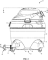
FIG. 3 is a side view of the vacuum cleaner with the drain system of the present disclosure, the drain system in an open position; -
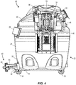
FIG. 4 is a side-cross sectional view of the vacuum cleaner with the drain system of the present disclosure taken along the lines A-A ofFig. 3 ; -
FIG. 5 is an exploded, perspective view of the drain system of the present disclosure; -
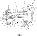
FIG. 6 is an enlarged view of the drain system ofFIG. 4 , the drain system in an open position; -
FIG. 7 is a front view the drain system of the present disclosure, the drain system in a closed position; -
FIG. 8 is bottom perspective view of a portion of the drain system of the present disclosure, the drain system between a closed position and a fully open position; -
FIG. 9 is a cross-sectional view of the drain system of the present disclosure disposed within a drain fitting of the vacuum taken along the line B-B ofFig. 2 ; -
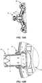
FIG. 10a is a top, cross-sectional view of the drain system of the present disclosure disposed within the drain fitting taken along the line C-C ofFig. 3 ; and -
FIG. 10b is a close-up view of a portion D of the cross-sectional view ofFig. 10a . - Referring now to
Figs. 1-3 , avacuum cleaner 20 constructed in accordance with the teachings of the disclosure is generally depicted. Thevacuum cleaner 20 includes atank 22 having asidewall 24, abase 25 and a closedbottom 26. Thetank 22 further includes anoutside surface 27 and an opening 28 disposed at thebase 25. Thesidewall 24 includes aninlet 29 that is adapted to receive a hose (not shown). Thetank 22 is enclosed by aremovable lid 30 that includes anoutlet 32, which is adapted to receive a hose (not shown) like theinlet 28, enabling the hose to be used in both a vacuuming and a blowing capacity. Thelid 30 houses a motor/impeller unit 34 (Fig. 4 ), which can be energized upon actuation of aswitch 36. A plurality ofcasters 38 or other wheels may be attached to thetank 22 to facilitate movement of thevacuum cleaner 20 about a worksite, for example. - In the present example, the
tank 22 is generally cylindrical, thelid 30 is correspondingly shaped, and both are manufactured from molded plastic. One of skill in the art will also appreciate that thetank 22 andlid 30 may be alternatively shaped and manufactured from other materials and processes and still fall within the scope of the present disclosure. - A
drain system 40 according to the present disclosure is further disposed in theopening 28 of thebase 25, as described in greater detail below. InFig. 1 , thedrain system 40 is depicted in a closed position, and inFigs. 2 and3 , thedrain system 40 is depicted in an open position, both of which are also described in more detail below. - Referring now to
Fig. 4 , a cross-sectional view of thevacuum cleaner 20 taken along the line A-A ofFig. 3 is depicted. The motor/impeller unit 34 includes amotor 35 from which arotatable shaft 46 extends. Avacuum impeller 48 is mounted to theshaft 46 for rotation within a vacuum chamber for generation of a low pressure area within thetank 22 for vacuuming purposes. Thevacuum cleaner 20 can be used to vacuum wet materials, in which case a bag is not used within thetank 22, and wet material gathered by thevacuum cleaner 20 is deposited directly within thetank 22. - Still referring to
Fig. 4 , thedrain system 40 is disposed within or adjacent to theopening 28 of thebase 25. Thedrain system 40 includes adrain tube 46 and acap 48 rotatably mounted to thedrain tube 46, as explained in more detail below. Thedrain system 40 may also include a drain fitting 42 disposed within theopening 28 of thetank 22 and secured to thetank 22. - Referring now to
Figs. 5 and6 , an exploded view and a detailed cross-sectional view, respectively, of thedrain system 40 with the drain fitting 42 disposed within theopening 28 of thebase 25 of thetank 22 is depicted. As illustrated therein, the drain fitting 42 further includes aninside surface 52 and anoutside surface 54, and at least onedrive rib 50 is disposed on theinside surface 52. Theoutside surface 54 includes a cylindrical portion having afirst flange 58 extending radially therefrom and a threadedportion 59. - The
drain fitting 42 further includes arear portion 60 having asecond flange 61 at one end and a threadedportion 62 disposed at an opposite end. The threadedportion 62 of therear portion 60 of the drain fitting 42 is disposed within theopening 28 of thetank 22 and ashoulder surface 61a (Fig. 6 ) of thesecond flange 61 helps secure the drain fitting 42 to thetank 22, such as by spinwelding, an adhesive or other attachment means. - The
drain system 40 further includes acollar 43 having acylindrical side wall 45 and a projection member orfoot 47 extending from theside wall 45 in a downward direction. Thecollar 43 is disposed between the first andsecond flanges foot 47 may hold or direct material leaving the drain system and may prevent thevacuum tank 22 from tipping during operation of thedrain system 40. More specifically, as thedrain tube 46 of thedrain system 40 is moved out of theopening 28 of thetank 22 and material is released, depending on the weight of the material being released, for example, thetank 22 may begin to tip over. In this case, even a slight tipping motion of thetank 22 will be stopped by the projecting member orfoot 47, as it will contact the ground or other surface onto which thetank 22 is disposed. Such contact will create force on thetank 22 in a direction opposite the force causing thetank 22 to slightly tip over, placing thetank 22 back into a balanced position and preventing any further tipping. - As further illustrated in
Fig. 5 , thedrain tube 46 of thedrain system 40 includes acylindrical body 64, afirst end 66 and asecond end 68 forming a pair of ends, and anexterior surface 70 extending along the length of thecylindrical body 64 between theends exterior surface 70 further includes at least onegroove 71 that is also disposed along the length of thecylindrical body 64. Thegroove 71 is adapted to receive the at least onedrive rib 50 of the drain fitting 42 to prevent rotation of the drain tube during movement, as explained in more detail below. In addition, thecap 48 is adapted to be rotatably mounted to thedrain tube 46 at thesecond end 68 and the drain fitting 42 is disposed near thefirst end 66 of thedrain tube 46. - The
first end 66 of thedrain tube 46 further includes aspherical radius 67, as illustrated inFigs. 5 and6 , for example. Thespherical radius 67 on thefirst end 66 of thedrain tube 46 inhibits a collection bag (not shown) in some examples of thevacuum cleaner 20 from rupturing while thevacuum cleaner 20 is in use. More specifically, when thevacuum cleaner 20 is on, the collection bag expands and contacts thespherical radius 67, which inhibits the bag from being damaged or ripped open, for example. - A
rim 72 is disposed on thesecond end 68 of thedrain tube 46. In addition, thedrain tube 46 further includes amain diameter portion 74 disposed near therim 72 and a reduced diameter portion 76 (Fig. 6 ) disposed near the other end or thefirst end 66 of thedrain tube 46. Anoutlet 77 having a slope or anangled step 78 is disposed between themain diameter portion 74 and the reduceddiameter portion 76, as illustrated inFig. 6 . Upon removal of thecap 48 from thedrain fitting 42 and/or theopening 28, thedrain tube 46 begins to slide out of the drain fitting 42 or theopening 28 in a first direction, axially, without any rotation. Theoutlet 77 permits material, such as one or more of any liquid or other wet matter or material, to leave thedrain tube 46 in a direction other than the first direction. In one example, the direction other than the first direction is a generally downward direction. - As illustrated in
Fig. 6 , thedrain tube 46 further comprises aninterior surface 80 having aflange 82 radially extending therefrom. Achannel 84 extends from theflange 82 and is disposed in acentral area 86 of thedrain tube 46. Thechannel 84 is adapted to receive a portion of thecap 48 of thedrain system 40 to help mount thecap 48 to thedrain tube 46, as explained in more detail below. - As further illustrated in
Fig. 6 , thecap 48 includes anexterior surface 88 having agrip 90 extending therefrom. Thegrip 90 allows a user to readily and easily grab theprojection 90 to twist thecap 48 onto and off of the drain fitting 42 disposed within or near theopening 28 of thevacuum tank 25. Thecap 48 further includes acylindrical side wall 94 having a recess and a threaded portion that engages the threadedportion 59 of the drain fitting 42 when thedrain system 40 is in a closed position (Fig. 1 ). - The
cap 48 further includes acap insert 92 disposed within the recess of theside wall 94. Thecap insert 92 includes atop portion 93 having atop surface 93a and abottom surface 93b and acylindrical side wall 95 that contacts thecylindrical side wall 94 of thecap 42 upon insertion into thecap 42. In other words, thecap insert 92 may be press fit into the recess of thecap 42, allowing exterior surfaces of thecylindrical side wall 95 of thecap insert 92 to directly contact interior surfaces of thecylindrical side wall 94 of thecap 42. - As further illustrated in
Fig. 6 , thecap insert 92 further includes atab 96 extending from thetop surface 93a and aninterior projection 97 extending from thebottom surface 93b. Theinterior projection 97 is threaded to receive afastener 98, which is adapted to removably mount or secure theinterior projection 97 of thecap 42 to thechannel 84 of thedrain tube 46. Thefastener 98 may include a truss screw that engages threads on the interior portion of theprojection 97 or a snap that is press fit into theprojection 97 to mount the same to thechannel 84, for example. As one of skill in the art will appreciate, thefastener 98 is not limited to either a truss screw or a snap, but may alternatively include any other fastening structure capable of mounting or securing theprojection 97 of thecap 48 to thechannel 84 of thedrain tube 46 and still fall within the scope of the present disclosure. - The
tab 96 extending from thetop surface 93a of thecap insert 92 aligns and fits within an interior portion of thegrip 90. More specifically, in one example, thetab 96 is rectangular in shape (Fig. 5 ) or more generally, thetab 96 matches the shape of thegrip 90, such that thetab 96 fits within thegrip 90, further securing and holding thetab 96 and, thus, thecap insert 92 to thecap 48. - While not illustrated in
Fig. 5 or6 , theexterior surface 70 of thedrain tube 46 may include a plurality of grooves (Fig. 9 ), such as fourgrooves 71, each of which also extends along the length of theexterior surface 70. The plurality ofgrooves 71 are equally spaced about theexterior surface 70 or an outside circumference of thedrain tube 46. In addition, eachgroove 71 of the four or plurality ofgrooves 71 is adapted to receive acorresponding drive rib 50 of a plurality of drive ribs of the drain fitting 42 upon insertion of thedrain tube 46 into the drain fitting 42 to prevent rotation of thedrain tube 46 during movement. In other words, while not illustrated inFig. 5 , for example, theinterior surface 52 of the drain fitting 42 may include more than onedrive rib 50, such as fourdrive ribs 50, that are equally spaced about theinterior surface 52, such that eachdrive rib 50 fits into a correspondinggroove 71. Such mating configuration between thegrooves 71 of thedrain tube 46 and thedrive ribs 50 of the drain fitting 42 prevents rotation of thedrain tube 46 when thecap 48 is removed from the drain fitting 42 to start draining thetank 22 and sliding movement of thedrain tube 46 occurs. - Referring now to
Figs. 7-9 , several views of thedrain system 40 of thevacuum 20 are provided. More specifically,Fig. 7 illustrates a front view of thedrain system 40 of the present disclosure disposed within thetank 22 of thevacuum 20, thedrain system 40 in a closed position.Fig. 8 is a bottom perspective view of a portion of thevacuum 20 anddrain system 40, illustrating another view of theoutlet 77 disposed between themain diameter portion 74 and the reduceddiameter portion 76 of thedrain tube 46. Theoutlet 77 directs liquid and/or wet material from thetank 22 in the generally downward direction, for example, as explained in greater detail above.Fig. 9 is a cross-sectional view of a portion of thedrain system 40 of the present disclosure disposed within the drain fitting 42 of thevacuum 20 taken along the lines B-B inFig. 2 . Threegrooves 71 of thedrain tube 46 are illustrated in an equally spaced configuration, as described above. Each of thegrooves 71 is capable of receiving one of thedrive ribs 50 of the drain fitting 42 to prevent rotation of thedrain tube 46 during movement, as also explained in more detail above. - Thus, from the foregoing, it can be seen that the
cap 48 is removably mounted to thedrain tube 46. As a result of this configuration, and in general, longitudinal movement of thecap 48 in turn moves thedrain tube 46 on which thecap 48 is mounted. Thedrain tube 46 is inserted into theopening 28 or the drain fitting 42 disposed within theopening 28 near thebase 25 of thetank 22 of thevacuum cleaner 20. More specifically, at least onegroove 71 of thetrain tube 46 receives at least onedrive rib 50 of theopening 28 or drain fitting 42 upon insertion intoopening 28 or thedrain fitting 42. This allows thedrain tube 46 to slide into and out of theopening 28 or drain fitting 42 along the at least onegroove 71 of thedrain tube 46, or in a direction parallel to a longitudinal axis of thedrain tube 46, without any rotation of thedrain tube 46. In other words, thedrain tube 46 is capable of moving in and out of theopening 28 or drain fitting 42 in a direction parallel to the longitudinal axis of thedrain tube 46, but is prevented from rotating. - To achieve a fully closed position of the
drain system 40, thecap 48 is secured to the drain fitting 42, for example. More specifically, the threaded portion of the cylindrical sidewall 94 (Fig. 6 ) of thecap 48 engages the threaded portion 60 (Fig. 6 ) of thedrain fitting 42. In other words, thecap 48 is removably secured to prevent material from exiting thetank 22 of thevacuum 20. When thecap 48 is in this position, thecap 48 is in a closed position. - When it is desired to move from the closed position to an open position to begin draining the
tank 22 of thevacuum 20, thecap 48 is removed, e.g., unscrewed, from thedrain fitting 42. This allows thedrain tube 46 to which thecap 48 is mounted to move as well, e.g., slide out of theopening 28 in a first direction. However, while thecap 48 is rotated or unscrewed, for example, to remove thecap 48 from thedrain fitting 42 and thedrain tube 46 is moved, thedrain tube 46 does not rotate. Instead, as explained, thedrain tube 46 only moves or slides along the longitudinal axis of thedrain tube 46 and in a direction parallel to the longitudinal axis of thedrain tube 46. This helps allow the tank material, such as any one or more of liquid or other liquid based matter, to be directed in a generally downward direction by theangled step 78 of thedrain tube 46 through theoutlet 77, resulting in a controlled and efficient draining of thetank 22. - Referring now to
Figs. 10a and 10b , a top cross-sectional view and a close-up view of a portion D of thedrain tube 46 secured to the drain fitting 42 are depicted. As illustrated inFig. 10b , eachgroove 71 includes at least onetab 71a disposed at thefirst end 66 of thedrain tube 46. Eachtab 71a extends in a radially outward direction from asurface 70 of thegroove 71. Thetabs 71a snag orcontact ribs 50a of the top andbottom drive ribs 50, as indicated inFig. 10b , preventing thedrain tube 46 from sliding all the way out of thetank 28 during operation of thedrain system 40. In other words, the interaction between thetabs 71a of thegrooves 71 and thedrive ribs 50 prevent the drain tube from being pulled all the way out of the drain fitting 42 or pushed all the way out by water pressure during operation of thedrain system 40. In addition, when thedrain tube 46 moves from the closed position to the open position, the drain fitting 42 gives the drain tube 46 a tighter fit the more thedrain tube 46 is pulled out of thedrain fitting 42. Thus, the increasingly tighter fit between thedrain tube 46 and the drain fitting 42 as thedrain tube 46 is moved from the closed position to the open position also prevents thedrain tube 46 from sliding all the way out of thetank 28 during operation of thedrain system 40. - When it is desired to remove the
drain tube 46 from the drain fitting 42, for example, the fastener 98 (Fig. 6 ) is first removed from thecap 42 from inside thetank 28, and thecap 42 is then able to be disconnected from thedrain tube 46. Thereafter, thedrain tube 46 is able to slide into the inside of thetank 28, allowing removal of thedrain tube 46 from thedrain fitting 42.
Claims (12)
- A vacuum cleaner (20) comprising:a tank (22) for collecting material having a base (25), an outside surface (27) and an opening (28) disposed near the base (25);a drain system (40) disposed adjacent the opening (28) and including a drain tube (46) having an outlet (77) and a cap (48) mounted to the drain tube (46) and removably secured to prevent material from exiting the drain system (40),the vacuum cleaner being characterized in that the drain system (40) further comprises a drain fitting (42) that is disposed within the opening (28) of the tank (22) and is secured to the tank (22), the drain fitting (42) further including an inside surface (52) and an outside surface (54), wherein at least one drive rib (50) is disposed on the inside surface (52);and in that, when the cap (48) is removed, the drain tube (46) slides out of the opening (28) in a first direction, and the outlet (77) permits material to leave the drain tube (46) in a direction other than the first direction.
- The vacuum cleaner (20) of claim 1, the drain system (40) further comprising:a plurality of drive ribs (50) that are disposed on the inside surface (52) of the drain fitting (42);a cylindrical portion that is on the outside surface (54) of the drain fitting (42), is disposed within the opening (28) of the tank (22), and has a flange (58) that extends radially therefrom and a threaded portion (59); anda cylindrical body (64) that is on the drain tube (46) and has an exterior surface (70) with a plurality of grooves (71) that receive the drive ribs (50) of the drain fitting (42) upon insertion of the drain tube (46) into the drain fitting (42).
- The vacuum cleaner (20) of claim 1, the drain tube (46) further comprising an interior surface (80) having a flange (82) radially extending therefrom and a channel (84) extending from an end portion of the flange (82), the channel (84) disposed in a central area (86) of the drain tube (46) and adapted to receive a portion of the cap (48) to help secure the cap (48) to the drain tube (46).
- The vacuum cleaner (20) of claim 1, the drain tube (46) further comprising a reduced diameter portion (76) disposed near the drain fitting (42), a main diameter portion (74) disposed near the cap (48) and an angled step (78) disposed between the reduced diameter portion (76) and the main diameter portion (74) for directing material through the outlet (77) of the drain tube (46).
- The vacuum cleaner (20) of claim 1, further comprising:a flange (82) that that extends radially from an interior surface (80) of the drain tube (46) and has a channel (84) that extends from an end of the flange (82);a grip (90) that extends from an exterior surface (88) of the cap (48);a cap insert (92) that is disposed within a recess in a cylindrical side wall (94) on the cap (48) and has a top portion (93);a tab (96) that extends from a top surface (93a) of the top portion (93) of the cap insert (92); anda projection (97) that extends from a bottom surface (93b) of the top portion (93) of the cap insert (92) and has an interior portion with threads the receive a fastener (98) that removably secures the cap (48) to the channel (84) of the drain tube (46).
- The vacuum cleaner (20) of claim 1,
wherein the outlet (77) is arranged so that material leaves the drain tube (46) in one direction, and upon removal of the cap (48), the drain tube (46) slides out of the opening (28) in a different direction. - The vacuum cleaner (20) of claim 6, the drain tube (46) further comprising:a first end (66) that has a spherical radius;a main diameter portion (74) disposed near an opposed second end (68); anda reduced diameter portion (76) disposed near the first end (66), wherein the outlet (77) is disposed between the main diameter portion (74) and the reduced diameter portion (76).
- The vacuum cleaner (20) of claim 6, the drain system (40) further comprising:at least one groove (71) that extends along the length of an exterior surface (70) of the drain tube (46) and is adapted to receive the drive rib (50) to prevent rotation of the drain tube (46).
- The vacuum cleaner (20) of claim 6, further comprising:a flange (82) that that extends radially from an interior surface (80) of the drain tube (46) and has a channel (84) that extends from an end of the flange (82);a grip (90) that extends from an exterior surface (88) of the cap (48);a cap insert (92) that is disposed within a recess in a cylindrical side wall (94) on the cap (48) and has a top portion (93);a tab (96) that extends from a top surface (93a) of the top portion (93) of the cap insert (92); anda projection (97) that extends from a bottom surface (93b) of the top portion (93) of the cap insert (92) and has an interior portion with threads the receive a fastener (98) that removably secures the cap (48) to the channel (84) of the drain tube (46).
- A method of draining a tank (22) of a wet/dry vacuum cleaner (20) comprising:mounting a cap (48) to a drain tube (46) having an outlet (77);removably securing the cap (48) to prevent material from exiting the drain tube (46);the method being characterized in that it further comprises:inserting the drain tube (46) into an opening (28) disposed near a base (25) of a wet/dry vacuum tank (22);removing the cap (48), to allow the drain tube (46) to slide out of the opening (28) in a first direction; andpermitting material to leave the drain tube (46) via the outlet (77) in a direction other than the first direction; andpreventing rotational movement of the drain tube (46) when the drain tube (46) slides out of the opening (28) in the first direction, wherein preventing rotational movement of the drain tube (46) comprises inserting a drive rib (50) into a groove (71) disposed on the drain tube (46), allowing the drain tube (46) to slide out of the opening (28) without rotation.
- The method of claim 10, wherein removably securing the cap (48) comprises engaging a threaded portion of a cylindrical sidewall (94) of the cap (48) to a threaded portion (60) of a drain fitting (42) disposed in the opening (28) of the tank (22).
- The method of claim 11, wherein permitting material to leave the tank (22) in a direction other than the first direction comprises forming an angled step (78) between a main diameter portion (74) and a reduced diameter portion (76) of the drain tube (46), and guiding material via the angled step (78) to the outlet (77) of the drain tube (46).
Applications Claiming Priority (1)
| Application Number | Priority Date | Filing Date | Title |
|---|---|---|---|
| US14/025,401 US9192270B2 (en) | 2013-09-12 | 2013-09-12 | Drain system and method for vacuum cleaner |
Publications (3)
| Publication Number | Publication Date |
|---|---|
| EP2848174A2 EP2848174A2 (en) | 2015-03-18 |
| EP2848174A3 EP2848174A3 (en) | 2015-08-05 |
| EP2848174B1 true EP2848174B1 (en) | 2016-12-21 |
Family
ID=51162509
Family Applications (1)
| Application Number | Title | Priority Date | Filing Date |
|---|---|---|---|
| EP14175737.7A Not-in-force EP2848174B1 (en) | 2013-09-12 | 2014-07-04 | Vacuum cleaner with a drain system and method for the vacuum cleaner |
Country Status (5)
| Country | Link |
|---|---|
| US (1) | US9192270B2 (en) |
| EP (1) | EP2848174B1 (en) |
| AU (1) | AU2014203761A1 (en) |
| CA (1) | CA2854519C (en) |
| MX (1) | MX351033B (en) |
Families Citing this family (19)
| Publication number | Priority date | Publication date | Assignee | Title |
|---|---|---|---|---|
| US10869586B2 (en) | 2016-11-17 | 2020-12-22 | Karcher North America, Inc. | Portable vacuum and related accessories |
| AU2017272322B2 (en) * | 2016-12-20 | 2019-11-07 | Bissell Inc. | Extraction cleaner with quick empty tank |
| USD874760S1 (en) * | 2017-09-13 | 2020-02-04 | Home Depot Product Authority, Llc | Vacuum |
| USD880087S1 (en) | 2017-09-13 | 2020-03-31 | Home Depot Product Authority, Llc | Vacuum |
| USD876739S1 (en) * | 2018-04-30 | 2020-02-25 | Emerson Electric Co. | Wet/dry vacuum cleaner |
| USD882892S1 (en) * | 2018-04-30 | 2020-04-28 | Emerson Electric Co. | Wet/dry vacuum cleaner |
| USD876738S1 (en) * | 2018-04-30 | 2020-02-25 | Emerson Electric Co. | Wet/dry vacuum cleaner |
| USD865305S1 (en) * | 2018-04-30 | 2019-10-29 | Emerson Electric Co. | Combined wet/dry vacuum cleaner |
| USD901112S1 (en) | 2018-04-30 | 2020-11-03 | Emerson Electric Co. | Wet/dry vacuum cleaner |
| USD876039S1 (en) * | 2018-04-30 | 2020-02-18 | Emerson Electric Co. | Wet/dry vacuum cleaner |
| USD933914S1 (en) * | 2019-05-03 | 2021-10-19 | Black & Decker Inc. | Vacuum cleaner |
| USD950173S1 (en) * | 2019-05-03 | 2022-04-26 | Black & Decker Inc. | Vacuum cleaner |
| USD946839S1 (en) * | 2019-05-03 | 2022-03-22 | Black & Decker Inc. | Vacuum cleaner |
| USD959073S1 (en) * | 2019-05-03 | 2022-07-26 | Black & Decker Inc. | Vacuum cleaner |
| CN111012242B (en) * | 2019-11-29 | 2021-07-20 | 湖州橘柚茜服饰有限公司 | A Garbage Sweeping and Recycling Device for Garment Production |
| US11653809B2 (en) | 2020-02-13 | 2023-05-23 | Techtronic Floor Care Technology Limited | Floor cleaner |
| CN116115130A (en) * | 2021-09-30 | 2023-05-16 | 添可智能科技有限公司 | Cleaning system, cleaning device and cleaning method |
| WO2025166816A1 (en) * | 2024-02-09 | 2025-08-14 | 云鲸智能创新(深圳)有限公司 | Wastewater tank, cleaning module, cleaning device, base station, cleaning system, and wastewater tank cleaning method |
| USD1109464S1 (en) * | 2024-05-21 | 2026-01-13 | Robert Thomas Metall- Und Elektrowerke Gmbh & Co. Kg | Vacuum cleaner |
Family Cites Families (32)
| Publication number | Priority date | Publication date | Assignee | Title |
|---|---|---|---|---|
| US2772037A (en) | 1954-02-16 | 1956-11-27 | Rieke Metal Products Corp | Pour spout closure for containers |
| US3493146A (en) * | 1967-05-18 | 1970-02-03 | Corco Inc | Liquid container with dispensing valve |
| US3496146A (en) | 1967-08-23 | 1970-02-17 | Du Pont | Preparation of glycol terephthalate linear polyester by direct esterification of terephthalic acid |
| US4133347A (en) * | 1977-10-31 | 1979-01-09 | Albert Mercer | Waste evacuation attachment for recreational vehicles |
| US4231595A (en) * | 1978-11-29 | 1980-11-04 | Knutsen Karl I | Waste dispensing device for recreational vehicles and the like |
| US4223702A (en) * | 1978-12-26 | 1980-09-23 | James Cook | Drain line for recreational vehicles |
| DE3410817A1 (en) | 1984-03-23 | 1985-10-03 | Esta Apparatebau GmbH & Co KG, 7913 Senden | CLEANING DEVICE FOR SWIMMING POOLS OR THE LIKE |
| US4858269A (en) | 1987-04-03 | 1989-08-22 | The Scott Fetzer Company | Wet/dry vac |
| US4854349A (en) * | 1987-04-28 | 1989-08-08 | Dennis Foreman | Sewage draining device for recreational vehicles or the like |
| US4799699A (en) | 1987-05-06 | 1989-01-24 | Shop-Vac Corporation | Dolly frame |
| US5023959A (en) * | 1989-04-03 | 1991-06-18 | Thetford Corporation | Extendable waste hose system |
| US5244003A (en) * | 1991-01-17 | 1993-09-14 | Tennant Company | Telescopic drain hose |
| US5263223A (en) | 1992-03-02 | 1993-11-23 | Von Schrader Company | Apparatus for cleaning interior surfaces |
| US5417460A (en) * | 1993-01-15 | 1995-05-23 | Valterra Products, Inc. | Apparatus for mounting a drain hose to an RV waste removal valve assembly |
| US5385233A (en) | 1993-12-01 | 1995-01-31 | Cmi International, Inc. | Portable bulk storage container |
| US5526547A (en) | 1994-10-03 | 1996-06-18 | William H. Williams | Wet and dry vacuum cleaner |
| US5954863A (en) | 1996-11-18 | 1999-09-21 | Loveless; Michael L. | Wet and dry vacuum with float valve system |
| US6237187B1 (en) | 1998-08-31 | 2001-05-29 | Emerson Electric Co. | Wet/dry vacuum dolly |
| US6219880B1 (en) | 1998-09-17 | 2001-04-24 | Pullman-Holt Corporation | Vacuum cleaner |
| DE29910800U1 (en) | 1999-06-22 | 2000-11-23 | SHP-Schlauch-Produktions GmbH, 23626 Ratekau | Device for draining liquid from a container |
| US6451078B2 (en) | 1999-07-07 | 2002-09-17 | Shop-Vac Corporation | Fitting for vacuum bags |
| CA2353784A1 (en) | 2000-09-21 | 2002-03-21 | Shop Vac Corporation | Automatic discharge assembly for a vacuum cleaner |
| US7203994B2 (en) | 2002-01-25 | 2007-04-17 | Smith Donald A | Compressed air vacuum cleaner |
| US7299522B1 (en) | 2002-01-25 | 2007-11-27 | Smith Donald A | Compressed air vacuum cleaner |
| US7653963B2 (en) | 2002-11-12 | 2010-02-02 | Black & Decker Inc. | AC/DC hand portable wet/dry vacuum having improved portability and convenience |
| US7363679B2 (en) | 2005-07-22 | 2008-04-29 | Whirlpool Corporation | Vacuum system |
| US8075650B2 (en) | 2006-10-11 | 2011-12-13 | Emerson Electric Co. | System, method, and apparatus for mounting a filter bag to a wet/dry vacuum |
| US7779505B2 (en) | 2007-03-09 | 2010-08-24 | Bissell Homecare, Inc. | Wet/dry vacuum cleaner |
| US7988162B2 (en) | 2007-07-03 | 2011-08-02 | Floyd Keith Sands | Auger dolly (an attachment for all handheld power earth augers) |
| WO2012031158A2 (en) | 2010-09-01 | 2012-03-08 | Techtronic Floor Care Technology Limited | Recovery tank assembly having a pour spout for an extractor cleaning machine |
| US8313396B1 (en) | 2011-04-20 | 2012-11-20 | Mailman Charles J | Tennis ball vacuum collector |
| US8997308B2 (en) * | 2012-07-24 | 2015-04-07 | Koblenz Electricia S.A. de C.V. | Wet/dry vacuum cleaner |
-
2013
- 2013-09-12 US US14/025,401 patent/US9192270B2/en active Active
-
2014
- 2014-06-17 CA CA2854519A patent/CA2854519C/en active Active
- 2014-07-04 EP EP14175737.7A patent/EP2848174B1/en not_active Not-in-force
- 2014-07-09 AU AU2014203761A patent/AU2014203761A1/en not_active Abandoned
- 2014-09-12 MX MX2014011040A patent/MX351033B/en active IP Right Grant
Non-Patent Citations (1)
| Title |
|---|
| None * |
Also Published As
| Publication number | Publication date |
|---|---|
| US9192270B2 (en) | 2015-11-24 |
| MX351033B (en) | 2017-09-28 |
| AU2014203761A1 (en) | 2015-03-26 |
| HK1205897A1 (en) | 2015-12-31 |
| US20150067978A1 (en) | 2015-03-12 |
| EP2848174A3 (en) | 2015-08-05 |
| CA2854519A1 (en) | 2015-03-12 |
| EP2848174A2 (en) | 2015-03-18 |
| CA2854519C (en) | 2021-05-25 |
| MX2014011040A (en) | 2016-06-30 |
Similar Documents
| Publication | Publication Date | Title |
|---|---|---|
| US9192270B2 (en) | Drain system and method for vacuum cleaner | |
| KR101318315B1 (en) | A cleaning appliance comprising a telescopic wand assembly retaining means | |
| EP3419490B3 (en) | Dirt-collection chamber and suction head for a vacuum cleaner | |
| AU709674B2 (en) | Apparatus for cleaning floors, carpets and the like | |
| RU2530795C2 (en) | Cleaner | |
| EP3653096B1 (en) | Vacuum cleaner | |
| US6347429B1 (en) | Wet/dry vacuum drain system | |
| EP1797809A2 (en) | Compact robot vacuum cleaner with cyclone | |
| US20220400920A1 (en) | Dirt separation device | |
| US20010005983A1 (en) | Fitting for vacuum bags | |
| US20160249777A1 (en) | Surface cleaning apparatus | |
| EP3653097A1 (en) | Vacuum cleaner | |
| MXPA01009739A (en) | Self-evacuating vacuum cleaner. | |
| HK1205897B (en) | Vacuum cleaner with a drain system and method for the vacuum cleaner | |
| EP1733671B1 (en) | Vacuum cleaner | |
| CA2314661C (en) | Wet/dry vacuum drain system | |
| MXPA98006796A (en) | Apparatus to clean floors, carpets and simi | |
| HK1016049B (en) | Apparatus for cleaning floors, carpets and the like |
Legal Events
| Date | Code | Title | Description |
|---|---|---|---|
| PUAI | Public reference made under article 153(3) epc to a published international application that has entered the european phase |
Free format text: ORIGINAL CODE: 0009012 |
|
| 17P | Request for examination filed |
Effective date: 20140704 |
|
| AK | Designated contracting states |
Kind code of ref document: A2 Designated state(s): AL AT BE BG CH CY CZ DE DK EE ES FI FR GB GR HR HU IE IS IT LI LT LU LV MC MK MT NL NO PL PT RO RS SE SI SK SM TR |
|
| AX | Request for extension of the european patent |
Extension state: BA ME |
|
| PUAL | Search report despatched |
Free format text: ORIGINAL CODE: 0009013 |
|
| AK | Designated contracting states |
Kind code of ref document: A3 Designated state(s): AL AT BE BG CH CY CZ DE DK EE ES FI FR GB GR HR HU IE IS IT LI LT LU LV MC MK MT NL NO PL PT RO RS SE SI SK SM TR |
|
| AX | Request for extension of the european patent |
Extension state: BA ME |
|
| RIC1 | Information provided on ipc code assigned before grant |
Ipc: A47L 5/36 20060101AFI20150701BHEP Ipc: F16L 55/115 20060101ALI20150701BHEP Ipc: A47L 11/40 20060101ALI20150701BHEP Ipc: A47L 7/00 20060101ALI20150701BHEP Ipc: B65D 47/20 20060101ALI20150701BHEP |
|
| REG | Reference to a national code |
Ref country code: HK Ref legal event code: DE Ref document number: 1205897 Country of ref document: HK |
|
| R17P | Request for examination filed (corrected) |
Effective date: 20160121 |
|
| RBV | Designated contracting states (corrected) |
Designated state(s): AL AT BE BG CH CY CZ DE DK EE ES FI FR GB GR HR HU IE IS IT LI LT LU LV MC MK MT NL NO PL PT RO RS SE SI SK SM TR |
|
| GRAP | Despatch of communication of intention to grant a patent |
Free format text: ORIGINAL CODE: EPIDOSNIGR1 |
|
| RIC1 | Information provided on ipc code assigned before grant |
Ipc: F16L 55/115 20060101ALI20160715BHEP Ipc: A47L 5/36 20060101AFI20160715BHEP Ipc: A47L 7/00 20060101ALI20160715BHEP Ipc: A47L 11/40 20060101ALI20160715BHEP Ipc: B65D 47/20 20060101ALI20160715BHEP |
|
| INTG | Intention to grant announced |
Effective date: 20160817 |
|
| STAA | Information on the status of an ep patent application or granted ep patent |
Free format text: STATUS: GRANT OF PATENT IS INTENDED |
|
| GRAS | Grant fee paid |
Free format text: ORIGINAL CODE: EPIDOSNIGR3 |
|
| GRAA | (expected) grant |
Free format text: ORIGINAL CODE: 0009210 |
|
| STAA | Information on the status of an ep patent application or granted ep patent |
Free format text: STATUS: THE PATENT HAS BEEN GRANTED |
|
| AK | Designated contracting states |
Kind code of ref document: B1 Designated state(s): AL AT BE BG CH CY CZ DE DK EE ES FI FR GB GR HR HU IE IS IT LI LT LU LV MC MK MT NL NO PL PT RO RS SE SI SK SM TR |
|
| REG | Reference to a national code |
Ref country code: GB Ref legal event code: FG4D |
|
| REG | Reference to a national code |
Ref country code: CH Ref legal event code: EP |
|
| REG | Reference to a national code |
Ref country code: IE Ref legal event code: FG4D |
|
| REG | Reference to a national code |
Ref country code: AT Ref legal event code: REF Ref document number: 854709 Country of ref document: AT Kind code of ref document: T Effective date: 20170115 |
|
| REG | Reference to a national code |
Ref country code: DE Ref legal event code: R096 Ref document number: 602014005601 Country of ref document: DE |
|
| PG25 | Lapsed in a contracting state [announced via postgrant information from national office to epo] |
Ref country code: LV Free format text: LAPSE BECAUSE OF FAILURE TO SUBMIT A TRANSLATION OF THE DESCRIPTION OR TO PAY THE FEE WITHIN THE PRESCRIBED TIME-LIMIT Effective date: 20161221 |
|
| REG | Reference to a national code |
Ref country code: LT Ref legal event code: MG4D |
|
| REG | Reference to a national code |
Ref country code: NL Ref legal event code: MP Effective date: 20161221 |
|
| PG25 | Lapsed in a contracting state [announced via postgrant information from national office to epo] |
Ref country code: SE Free format text: LAPSE BECAUSE OF FAILURE TO SUBMIT A TRANSLATION OF THE DESCRIPTION OR TO PAY THE FEE WITHIN THE PRESCRIBED TIME-LIMIT Effective date: 20161221 Ref country code: LT Free format text: LAPSE BECAUSE OF FAILURE TO SUBMIT A TRANSLATION OF THE DESCRIPTION OR TO PAY THE FEE WITHIN THE PRESCRIBED TIME-LIMIT Effective date: 20161221 Ref country code: NO Free format text: LAPSE BECAUSE OF FAILURE TO SUBMIT A TRANSLATION OF THE DESCRIPTION OR TO PAY THE FEE WITHIN THE PRESCRIBED TIME-LIMIT Effective date: 20170321 Ref country code: GR Free format text: LAPSE BECAUSE OF FAILURE TO SUBMIT A TRANSLATION OF THE DESCRIPTION OR TO PAY THE FEE WITHIN THE PRESCRIBED TIME-LIMIT Effective date: 20170322 |
|
| PG25 | Lapsed in a contracting state [announced via postgrant information from national office to epo] |
Ref country code: RS Free format text: LAPSE BECAUSE OF FAILURE TO SUBMIT A TRANSLATION OF THE DESCRIPTION OR TO PAY THE FEE WITHIN THE PRESCRIBED TIME-LIMIT Effective date: 20161221 Ref country code: FI Free format text: LAPSE BECAUSE OF FAILURE TO SUBMIT A TRANSLATION OF THE DESCRIPTION OR TO PAY THE FEE WITHIN THE PRESCRIBED TIME-LIMIT Effective date: 20161221 Ref country code: HR Free format text: LAPSE BECAUSE OF FAILURE TO SUBMIT A TRANSLATION OF THE DESCRIPTION OR TO PAY THE FEE WITHIN THE PRESCRIBED TIME-LIMIT Effective date: 20161221 |
|
| REG | Reference to a national code |
Ref country code: FR Ref legal event code: PLFP Year of fee payment: 4 |
|
| PG25 | Lapsed in a contracting state [announced via postgrant information from national office to epo] |
Ref country code: NL Free format text: LAPSE BECAUSE OF FAILURE TO SUBMIT A TRANSLATION OF THE DESCRIPTION OR TO PAY THE FEE WITHIN THE PRESCRIBED TIME-LIMIT Effective date: 20161221 |
|
| PG25 | Lapsed in a contracting state [announced via postgrant information from national office to epo] |
Ref country code: CZ Free format text: LAPSE BECAUSE OF FAILURE TO SUBMIT A TRANSLATION OF THE DESCRIPTION OR TO PAY THE FEE WITHIN THE PRESCRIBED TIME-LIMIT Effective date: 20161221 Ref country code: IS Free format text: LAPSE BECAUSE OF FAILURE TO SUBMIT A TRANSLATION OF THE DESCRIPTION OR TO PAY THE FEE WITHIN THE PRESCRIBED TIME-LIMIT Effective date: 20170421 Ref country code: RO Free format text: LAPSE BECAUSE OF FAILURE TO SUBMIT A TRANSLATION OF THE DESCRIPTION OR TO PAY THE FEE WITHIN THE PRESCRIBED TIME-LIMIT Effective date: 20161221 Ref country code: SK Free format text: LAPSE BECAUSE OF FAILURE TO SUBMIT A TRANSLATION OF THE DESCRIPTION OR TO PAY THE FEE WITHIN THE PRESCRIBED TIME-LIMIT Effective date: 20161221 Ref country code: EE Free format text: LAPSE BECAUSE OF FAILURE TO SUBMIT A TRANSLATION OF THE DESCRIPTION OR TO PAY THE FEE WITHIN THE PRESCRIBED TIME-LIMIT Effective date: 20161221 |
|
| PG25 | Lapsed in a contracting state [announced via postgrant information from national office to epo] |
Ref country code: SM Free format text: LAPSE BECAUSE OF FAILURE TO SUBMIT A TRANSLATION OF THE DESCRIPTION OR TO PAY THE FEE WITHIN THE PRESCRIBED TIME-LIMIT Effective date: 20161221 Ref country code: ES Free format text: LAPSE BECAUSE OF FAILURE TO SUBMIT A TRANSLATION OF THE DESCRIPTION OR TO PAY THE FEE WITHIN THE PRESCRIBED TIME-LIMIT Effective date: 20161221 Ref country code: IT Free format text: LAPSE BECAUSE OF FAILURE TO SUBMIT A TRANSLATION OF THE DESCRIPTION OR TO PAY THE FEE WITHIN THE PRESCRIBED TIME-LIMIT Effective date: 20161221 Ref country code: BE Free format text: LAPSE BECAUSE OF FAILURE TO SUBMIT A TRANSLATION OF THE DESCRIPTION OR TO PAY THE FEE WITHIN THE PRESCRIBED TIME-LIMIT Effective date: 20161221 Ref country code: BG Free format text: LAPSE BECAUSE OF FAILURE TO SUBMIT A TRANSLATION OF THE DESCRIPTION OR TO PAY THE FEE WITHIN THE PRESCRIBED TIME-LIMIT Effective date: 20170321 Ref country code: PT Free format text: LAPSE BECAUSE OF FAILURE TO SUBMIT A TRANSLATION OF THE DESCRIPTION OR TO PAY THE FEE WITHIN THE PRESCRIBED TIME-LIMIT Effective date: 20170421 Ref country code: PL Free format text: LAPSE BECAUSE OF FAILURE TO SUBMIT A TRANSLATION OF THE DESCRIPTION OR TO PAY THE FEE WITHIN THE PRESCRIBED TIME-LIMIT Effective date: 20161221 |
|
| REG | Reference to a national code |
Ref country code: DE Ref legal event code: R097 Ref document number: 602014005601 Country of ref document: DE |
|
| PLBE | No opposition filed within time limit |
Free format text: ORIGINAL CODE: 0009261 |
|
| STAA | Information on the status of an ep patent application or granted ep patent |
Free format text: STATUS: NO OPPOSITION FILED WITHIN TIME LIMIT |
|
| 26N | No opposition filed |
Effective date: 20170922 |
|
| PG25 | Lapsed in a contracting state [announced via postgrant information from national office to epo] |
Ref country code: DK Free format text: LAPSE BECAUSE OF FAILURE TO SUBMIT A TRANSLATION OF THE DESCRIPTION OR TO PAY THE FEE WITHIN THE PRESCRIBED TIME-LIMIT Effective date: 20161221 |
|
| REG | Reference to a national code |
Ref country code: HK Ref legal event code: GR Ref document number: 1205897 Country of ref document: HK |
|
| PG25 | Lapsed in a contracting state [announced via postgrant information from national office to epo] |
Ref country code: SI Free format text: LAPSE BECAUSE OF FAILURE TO SUBMIT A TRANSLATION OF THE DESCRIPTION OR TO PAY THE FEE WITHIN THE PRESCRIBED TIME-LIMIT Effective date: 20161221 |
|
| REG | Reference to a national code |
Ref country code: CH Ref legal event code: PL |
|
| REG | Reference to a national code |
Ref country code: IE Ref legal event code: MM4A |
|
| PG25 | Lapsed in a contracting state [announced via postgrant information from national office to epo] |
Ref country code: LI Free format text: LAPSE BECAUSE OF NON-PAYMENT OF DUE FEES Effective date: 20170731 Ref country code: CH Free format text: LAPSE BECAUSE OF NON-PAYMENT OF DUE FEES Effective date: 20170731 Ref country code: IE Free format text: LAPSE BECAUSE OF NON-PAYMENT OF DUE FEES Effective date: 20170704 |
|
| REG | Reference to a national code |
Ref country code: FR Ref legal event code: PLFP Year of fee payment: 5 |
|
| PG25 | Lapsed in a contracting state [announced via postgrant information from national office to epo] |
Ref country code: LU Free format text: LAPSE BECAUSE OF NON-PAYMENT OF DUE FEES Effective date: 20170704 |
|
| PGFP | Annual fee paid to national office [announced via postgrant information from national office to epo] |
Ref country code: FR Payment date: 20180612 Year of fee payment: 5 |
|
| PG25 | Lapsed in a contracting state [announced via postgrant information from national office to epo] |
Ref country code: MT Free format text: LAPSE BECAUSE OF NON-PAYMENT OF DUE FEES Effective date: 20170704 |
|
| REG | Reference to a national code |
Ref country code: AT Ref legal event code: UEP Ref document number: 854709 Country of ref document: AT Kind code of ref document: T Effective date: 20161221 |
|
| PG25 | Lapsed in a contracting state [announced via postgrant information from national office to epo] |
Ref country code: MC Free format text: LAPSE BECAUSE OF FAILURE TO SUBMIT A TRANSLATION OF THE DESCRIPTION OR TO PAY THE FEE WITHIN THE PRESCRIBED TIME-LIMIT Effective date: 20161221 Ref country code: HU Free format text: LAPSE BECAUSE OF FAILURE TO SUBMIT A TRANSLATION OF THE DESCRIPTION OR TO PAY THE FEE WITHIN THE PRESCRIBED TIME-LIMIT; INVALID AB INITIO Effective date: 20140704 |
|
| PG25 | Lapsed in a contracting state [announced via postgrant information from national office to epo] |
Ref country code: CY Free format text: LAPSE BECAUSE OF FAILURE TO SUBMIT A TRANSLATION OF THE DESCRIPTION OR TO PAY THE FEE WITHIN THE PRESCRIBED TIME-LIMIT Effective date: 20161221 |
|
| PG25 | Lapsed in a contracting state [announced via postgrant information from national office to epo] |
Ref country code: MK Free format text: LAPSE BECAUSE OF FAILURE TO SUBMIT A TRANSLATION OF THE DESCRIPTION OR TO PAY THE FEE WITHIN THE PRESCRIBED TIME-LIMIT Effective date: 20161221 |
|
| PG25 | Lapsed in a contracting state [announced via postgrant information from national office to epo] |
Ref country code: TR Free format text: LAPSE BECAUSE OF FAILURE TO SUBMIT A TRANSLATION OF THE DESCRIPTION OR TO PAY THE FEE WITHIN THE PRESCRIBED TIME-LIMIT Effective date: 20161221 |
|
| PG25 | Lapsed in a contracting state [announced via postgrant information from national office to epo] |
Ref country code: FR Free format text: LAPSE BECAUSE OF NON-PAYMENT OF DUE FEES Effective date: 20190731 |
|
| PG25 | Lapsed in a contracting state [announced via postgrant information from national office to epo] |
Ref country code: AL Free format text: LAPSE BECAUSE OF FAILURE TO SUBMIT A TRANSLATION OF THE DESCRIPTION OR TO PAY THE FEE WITHIN THE PRESCRIBED TIME-LIMIT Effective date: 20161221 |
|
| REG | Reference to a national code |
Ref country code: AT Ref legal event code: MM01 Ref document number: 854709 Country of ref document: AT Kind code of ref document: T Effective date: 20190704 |
|
| PG25 | Lapsed in a contracting state [announced via postgrant information from national office to epo] |
Ref country code: AT Free format text: LAPSE BECAUSE OF NON-PAYMENT OF DUE FEES Effective date: 20190704 |
|
| PGFP | Annual fee paid to national office [announced via postgrant information from national office to epo] |
Ref country code: GB Payment date: 20230608 Year of fee payment: 10 |
|
| PGFP | Annual fee paid to national office [announced via postgrant information from national office to epo] |
Ref country code: DE Payment date: 20230613 Year of fee payment: 10 |
|
| REG | Reference to a national code |
Ref country code: DE Ref legal event code: R119 Ref document number: 602014005601 Country of ref document: DE |
|
| GBPC | Gb: european patent ceased through non-payment of renewal fee |
Effective date: 20240704 |
|
| PG25 | Lapsed in a contracting state [announced via postgrant information from national office to epo] |
Ref country code: DE Free format text: LAPSE BECAUSE OF NON-PAYMENT OF DUE FEES Effective date: 20250201 |
|
| PG25 | Lapsed in a contracting state [announced via postgrant information from national office to epo] |
Ref country code: GB Free format text: LAPSE BECAUSE OF NON-PAYMENT OF DUE FEES Effective date: 20240704 |