EP2847845B1 - System for control and power supply of turbomachines of a helicopter - Google Patents
System for control and power supply of turbomachines of a helicopter Download PDFInfo
- Publication number
- EP2847845B1 EP2847845B1 EP13727264.7A EP13727264A EP2847845B1 EP 2847845 B1 EP2847845 B1 EP 2847845B1 EP 13727264 A EP13727264 A EP 13727264A EP 2847845 B1 EP2847845 B1 EP 2847845B1
- Authority
- EP
- European Patent Office
- Prior art keywords
- converter
- generator
- contactor
- apu
- contactors
- Prior art date
- Legal status (The legal status is an assumption and is not a legal conclusion. Google has not performed a legal analysis and makes no representation as to the accuracy of the status listed.)
- Active
Links
- 239000007858 starting material Substances 0.000 claims description 13
- 239000011159 matrix material Substances 0.000 claims description 12
- 238000002347 injection Methods 0.000 description 5
- 239000007924 injection Substances 0.000 description 5
- 239000003990 capacitor Substances 0.000 description 3
- 230000005540 biological transmission Effects 0.000 description 1
- 239000003638 chemical reducing agent Substances 0.000 description 1
- 230000000295 complement effect Effects 0.000 description 1
- 238000010586 diagram Methods 0.000 description 1
- 238000006073 displacement reaction Methods 0.000 description 1
- 238000009396 hybridization Methods 0.000 description 1
- 238000002955 isolation Methods 0.000 description 1
- 238000012423 maintenance Methods 0.000 description 1
- 238000011176 pooling Methods 0.000 description 1
- 230000002441 reversible effect Effects 0.000 description 1
- 238000004513 sizing Methods 0.000 description 1
- 238000006467 substitution reaction Methods 0.000 description 1
Images
Classifications
-
- F—MECHANICAL ENGINEERING; LIGHTING; HEATING; WEAPONS; BLASTING
- F02—COMBUSTION ENGINES; HOT-GAS OR COMBUSTION-PRODUCT ENGINE PLANTS
- F02N—STARTING OF COMBUSTION ENGINES; STARTING AIDS FOR SUCH ENGINES, NOT OTHERWISE PROVIDED FOR
- F02N11/00—Starting of engines by means of electric motors
- F02N11/08—Circuits or control means specially adapted for starting of engines
- F02N11/0862—Circuits or control means specially adapted for starting of engines characterised by the electrical power supply means, e.g. battery
-
- B64D27/026—
-
- B—PERFORMING OPERATIONS; TRANSPORTING
- B64—AIRCRAFT; AVIATION; COSMONAUTICS
- B64D—EQUIPMENT FOR FITTING IN OR TO AIRCRAFT; FLIGHT SUITS; PARACHUTES; ARRANGEMENTS OR MOUNTING OF POWER PLANTS OR PROPULSION TRANSMISSIONS IN AIRCRAFT
- B64D27/00—Arrangement or mounting of power plant in aircraft; Aircraft characterised thereby
- B64D27/02—Aircraft characterised by the type or position of power plant
- B64D27/24—Aircraft characterised by the type or position of power plant using steam, electricity, or spring force
-
- B—PERFORMING OPERATIONS; TRANSPORTING
- B64—AIRCRAFT; AVIATION; COSMONAUTICS
- B64D—EQUIPMENT FOR FITTING IN OR TO AIRCRAFT; FLIGHT SUITS; PARACHUTES; ARRANGEMENTS OR MOUNTING OF POWER PLANTS OR PROPULSION TRANSMISSIONS IN AIRCRAFT
- B64D31/00—Power plant control; Arrangement thereof
-
- F—MECHANICAL ENGINEERING; LIGHTING; HEATING; WEAPONS; BLASTING
- F02—COMBUSTION ENGINES; HOT-GAS OR COMBUSTION-PRODUCT ENGINE PLANTS
- F02N—STARTING OF COMBUSTION ENGINES; STARTING AIDS FOR SUCH ENGINES, NOT OTHERWISE PROVIDED FOR
- F02N11/00—Starting of engines by means of electric motors
- F02N11/04—Starting of engines by means of electric motors the motors being associated with current generators
-
- F—MECHANICAL ENGINEERING; LIGHTING; HEATING; WEAPONS; BLASTING
- F02—COMBUSTION ENGINES; HOT-GAS OR COMBUSTION-PRODUCT ENGINE PLANTS
- F02N—STARTING OF COMBUSTION ENGINES; STARTING AIDS FOR SUCH ENGINES, NOT OTHERWISE PROVIDED FOR
- F02N11/00—Starting of engines by means of electric motors
- F02N11/08—Circuits or control means specially adapted for starting of engines
- F02N11/0848—Circuits or control means specially adapted for starting of engines with means for detecting successful engine start, e.g. to stop starter actuation
-
- H—ELECTRICITY
- H02—GENERATION; CONVERSION OR DISTRIBUTION OF ELECTRIC POWER
- H02J—CIRCUIT ARRANGEMENTS OR SYSTEMS FOR SUPPLYING OR DISTRIBUTING ELECTRIC POWER; SYSTEMS FOR STORING ELECTRIC ENERGY
- H02J3/00—Circuit arrangements for ac mains or ac distribution networks
- H02J3/38—Arrangements for parallely feeding a single network by two or more generators, converters or transformers
-
- H—ELECTRICITY
- H02—GENERATION; CONVERSION OR DISTRIBUTION OF ELECTRIC POWER
- H02J—CIRCUIT ARRANGEMENTS OR SYSTEMS FOR SUPPLYING OR DISTRIBUTING ELECTRIC POWER; SYSTEMS FOR STORING ELECTRIC ENERGY
- H02J5/00—Circuit arrangements for transfer of electric power between ac networks and dc networks
-
- B—PERFORMING OPERATIONS; TRANSPORTING
- B64—AIRCRAFT; AVIATION; COSMONAUTICS
- B64D—EQUIPMENT FOR FITTING IN OR TO AIRCRAFT; FLIGHT SUITS; PARACHUTES; ARRANGEMENTS OR MOUNTING OF POWER PLANTS OR PROPULSION TRANSMISSIONS IN AIRCRAFT
- B64D2221/00—Electric power distribution systems onboard aircraft
-
- H—ELECTRICITY
- H02—GENERATION; CONVERSION OR DISTRIBUTION OF ELECTRIC POWER
- H02J—CIRCUIT ARRANGEMENTS OR SYSTEMS FOR SUPPLYING OR DISTRIBUTING ELECTRIC POWER; SYSTEMS FOR STORING ELECTRIC ENERGY
- H02J2310/00—The network for supplying or distributing electric power characterised by its spatial reach or by the load
- H02J2310/40—The network being an on-board power network, i.e. within a vehicle
- H02J2310/44—The network being an on-board power network, i.e. within a vehicle for aircrafts
-
- Y—GENERAL TAGGING OF NEW TECHNOLOGICAL DEVELOPMENTS; GENERAL TAGGING OF CROSS-SECTIONAL TECHNOLOGIES SPANNING OVER SEVERAL SECTIONS OF THE IPC; TECHNICAL SUBJECTS COVERED BY FORMER USPC CROSS-REFERENCE ART COLLECTIONS [XRACs] AND DIGESTS
- Y02—TECHNOLOGIES OR APPLICATIONS FOR MITIGATION OR ADAPTATION AGAINST CLIMATE CHANGE
- Y02T—CLIMATE CHANGE MITIGATION TECHNOLOGIES RELATED TO TRANSPORTATION
- Y02T50/00—Aeronautics or air transport
- Y02T50/40—Weight reduction
-
- Y—GENERAL TAGGING OF NEW TECHNOLOGICAL DEVELOPMENTS; GENERAL TAGGING OF CROSS-SECTIONAL TECHNOLOGIES SPANNING OVER SEVERAL SECTIONS OF THE IPC; TECHNICAL SUBJECTS COVERED BY FORMER USPC CROSS-REFERENCE ART COLLECTIONS [XRACs] AND DIGESTS
- Y02—TECHNOLOGIES OR APPLICATIONS FOR MITIGATION OR ADAPTATION AGAINST CLIMATE CHANGE
- Y02T—CLIMATE CHANGE MITIGATION TECHNOLOGIES RELATED TO TRANSPORTATION
- Y02T50/00—Aeronautics or air transport
- Y02T50/60—Efficient propulsion technologies, e.g. for aircraft
Definitions
- the invention relates to the field of electrical hybridization of the propulsion of helicopters and other rotorcraft comprising at least one main rotor provided with blades and more particularly it relates to a control system and power supply of at least one electric motor coupled to the turbomachine or the main gearbox (BTP) of the rotorcraft.
- BTP main gearbox
- the main gearbox connects an output shaft of the turbomachine to the main rotor shaft provided with blades via a speed reducer.
- an auxiliary power unit or APU (Auxiliary Power Unit) provides in particular the edge energy when the engines of the rotorcraft are stopped, especially on the ground before their rotation.
- the APU is in the form of a turbomachine driving an electric generator.
- the latter can be designed as a starter / generator or S / G ("Starter / Generator") which operates in engine mode to ensure the start of the APU and in electric generator mode after ignition of the turbine engine and when it has reached a sufficient speed of rotation.
- S / G is supplied with multiphase voltage. It is well known for this purpose to use a DC / AC converter device which converts into AC voltages a DC voltage supplied from a battery via a DC / DC boost converter.
- aircraft power supply systems comprising such APUs are disclosed in patent applications. US20110273011 and EP2404775 .
- the present invention is part of this approach and proposes for this purpose a control system and power supply of at least one helicopter engine / generator comprising a first DC / AC converter for selectively providing, according to the respective positions contactors of a connection matrix actuated from an electronic control circuit, an electrical energy alternative to said at least one motor / generator, said first DC / AC converter being supplied with DC voltage by a voltage supply device delivering a voltage continuous Vdc and formed either by a rectifying circuit of an AC voltage delivered via a contactor by a starter / generator of an APU or by a voltage-boosting DC / DC converter powered from a battery via a contactor, said connection matrix further comprising a contactor for paralleling said first DC / AC converter with said sec DC / AC converter to enable, once at least one of said engines / generators started, an additional power injection from said starter / generator APU.
- the provision of the same electrical resource between two systems, namely the starter / generator of the APU and the engines / generators of the BTP or turbomachines, which do not work at the same time and require substantially the same level of electrical power, is particularly advantageous in that it results, without over-sizing of the common power supply device, by a reduction in the number of housings, harnesses and interfaces, thus a reduction in weight, bulk and costs .
- said DC / DC voltage booster converter is obtained by placing in series a three-phase inductor and a second DC / AC converter via at least one contactor.
- Such an arrangement in which the DC / AC converter device also converts into AC voltage a DC voltage supplied from a battery via a three-phase inductor allows the start of the APU.
- connection matrix comprises at least one contactor for connecting said first DC / AC converter to a first motor / generator and at least one contactor for connecting said second DC / AC converter to a second motor / generator.
- a helicopter and more generally a rotorcraft has at least one main rotor provided with blades whose rotation allows its lift and its displacement.
- This main rotor is driven by one or more turbomachines through a transmission mechanism and speed reduction known as the main gearbox (BTP).
- BTP main gearbox
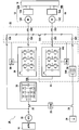
- the figure 1 shows a BTP 10 in engagement with respectively two turbomachines 12, 14 each comprising a gas generator 12A, 14A, a free turbine 12B, 14B driven by the gas flow generated by the gas generator and a reversible electric machine 12C, 14C constituted an electric motor capable of operating as an electric generator and mechanically coupled to the gas generator.
- the reference 16 designates a power auxiliary generator (or APU Auxiliary Power Unit) which is mechanically coupled to an electric machine 18 forming starter / generator (or S / G for Startor / Generator) and the reference 20 a battery.
- the starter / generator 18 typically delivers a three-phase voltage of 115Vac via a contactor 22 and the battery 20 a DC voltage of 28Vdc via a contactor 24, both voltages usual in aeronautical matter, under the control of a control unit 26.
- the control and power supply system 28 for the engines / generators 12C, 14C of the helicopter comprises a first DC / AC converter 30 intended to selectively supply, according to the contactor positions 320, 322, 324, 326, 328, 330 of a connection matrix 32 actuated from an electronic control circuit 34, an electrical energy alternative to the motors / generators, this first DC / AC converter being supplied with DC voltage by a supply device delivering a DC voltage Vdc and formed either by a diode rectifier circuit (non-controlled rectifier) of a alternating voltage delivered by the starter / generator 18 or by a DC / DC voltage-boosting converter 38 supplied from the battery 20.
- a supply device delivering a DC voltage Vdc and formed either by a diode rectifier circuit (non-controlled rectifier) of a alternating voltage delivered by the starter / generator 18 or by a DC / DC voltage-boosting converter 38 supplied from the battery 20.
- the first DC / AC converter 30 is constituted by a 3-phase inverter (thus with 6 switches) possibly preceded, as illustrated, by a protection device comprising a controlled switch followed by a capacitor in parallel.
- the switches forming the inverter are commonly IGBTs on which antiparallel diodes are mounted and whose switching is ensured by the electronic control circuit 34.
- the uncontrolled rectifying circuit 36 is advantageously constituted by a three-phase diode bridge delivering a rectified and filtered voltage of 270 Vdc across a capacitor, which voltage is usual in the aeronautical field.
- the DC / DC voltage-boosting converter 38 consists of placing in series via the connection matrix 32 a three-phase inductor 380 and a second DC / AC converter 382. Like the first converter, this second converter is also constituted by a 3-phase inverter with 6 switches possibly preceded, as illustrated, by a protection device comprising a controlled switch followed by a capacitor in parallel.
- the switches forming the inverter are commonly IGBTs on which antiparallel diodes are mounted and whose switching is ensured by the electronic control circuit 34.
- the electronic control circuit 34 providing the control of the connection matrix 32 and the two DC / AC converters 30, 38 can be mounted in a single control unit then preferably integrating the control unit 26 or arranged separately as illustrated.
- the structure of the invention based on a bridge rectifier, two inverters and a set of contactors makes it possible to manage these various functions very simply as follows (the preferential embodiment is commented on in connection with the control of the two engines of the gas generators but, of course, it finds application to the control of a single engine of the BTP for example):
- the second DC / AC converter 38 is used in active rectifier (three-phase booster) to obtain a voltage Vdc of the order of 270Vdc (the contactors 320 and 322 are then closed)
- the first DC / AC converter 30 controlling the starter / generator 18 of the APU from this DC voltage Vdc via the contactors 324, 326 then closed, the contactor 22 and the contactors 328, 330 and 332 being open.
- the start of the turbomachines from the mains voltage 115 Vac supplied by the S / G 18 of the APU can be made in turn.
- This voltage once the contactor 22 is closed, is supplied to the uncontrolled rectifier circuit 36 which delivers the rectified and filtered voltage Vdc, the two DC / AC converters 30, 382 each driving, through the series contactors 324, 330 and 322, 332 respectively, an electric motor 12C, 14C allowing the simultaneous start (if necessary) of the two turbomachines, the contactors 24, 320, 326 and 328 then being open.
- turbomachines can also to proceed from the low voltage from the battery 20 similarly to the start of the APU.
- the first turbine engine being started its engine electric can be used as a generator to provide the energy required to start the second turbomachine, then closing the contactors 322 and 332, the contactors 24 and 320 being simultaneously open.
- This also makes it possible to completely do without an alternative source (via the APU or any other generator) to allow the startup of the turbomachines.
- an additional power can be injected into one of the turbomachines from the S / G 18 operating as a generator, either transiently or permanently.
- the S / G 18 supplies the uncontrolled rectifying circuit 36 to create the voltage Vdc used by each DC / AC converter 30, 382 to drive via their respective series contactors 324, 330 and 322, 332 the electric motor 12C, 14C associated with each gas generator.
- the pooling of the electronic power devices makes it possible to produce a multifunctional control and power supply system and in particular, with the same inverter, to control several electric motors / generators.
- the use of a common system for the APU start control unit and for the electric generators allows an appreciable reduction in mass, bulk and cost, in comparison with the use of power supply systems. respective dedicated.
- the control and power system can advantageously be disposed in the central part of the helicopter, close to its primary electric core, which optimizes the entire electrical architecture.
Description
L'invention concerne le domaine de l'hybridation électrique de la propulsion des hélicoptères et autres giravions comportant au moins un rotor principal muni de pales et plus particulièrement elle se rapporte à un système de commande et d'alimentation en énergie d'au moins un moteur électrique couplé à la turbomachine ou à la boite de transmission principale (BTP) du giravion.The invention relates to the field of electrical hybridization of the propulsion of helicopters and other rotorcraft comprising at least one main rotor provided with blades and more particularly it relates to a control system and power supply of at least one electric motor coupled to the turbomachine or the main gearbox (BTP) of the rotorcraft.
Dans un tel giravion, la boite de transmission principale relie un arbre de sortie de la turbomachine à l'arbre du rotor principal muni de pales via un réducteur de vitesse. En outre, un groupe auxiliaire de puissance ou APU ("Auxiliary Power Unit") fournit notamment l'énergie de bord lorsque les moteurs du giravion sont à l'arrêt, notamment au sol avant leur mise en rotation.In such a rotorcraft, the main gearbox connects an output shaft of the turbomachine to the main rotor shaft provided with blades via a speed reducer. In addition, an auxiliary power unit or APU (Auxiliary Power Unit) provides in particular the edge energy when the engines of the rotorcraft are stopped, especially on the ground before their rotation.
L'APU se présente sous la forme d'une turbomachine entraînant un générateur électrique. Ce dernier peut être conçu comme démarreur/générateur ou S/G ("Starter/Generator") qui fonctionne en mode moteur pour assurer le démarrage de l'APU et en mode générateur électrique après allumage de la turbomachine et lorsque celle-ci a atteint une vitesse de rotation suffisante. En mode de fonctionnement moteur, le S/G est alimenté en tension multiphasée. Il est bien connu à cet effet d'utiliser un dispositif convertisseur continu/alternatif à onduleurs qui transforme en tensions alternatives une tension continue fournie à partir d'une batterie via un convertisseur continu/continu élévateur de tension.The APU is in the form of a turbomachine driving an electric generator. The latter can be designed as a starter / generator or S / G ("Starter / Generator") which operates in engine mode to ensure the start of the APU and in electric generator mode after ignition of the turbine engine and when it has reached a sufficient speed of rotation. In motor operating mode, the S / G is supplied with multiphase voltage. It is well known for this purpose to use a DC / AC converter device which converts into AC voltages a DC voltage supplied from a battery via a DC / DC boost converter.
Des systèmes d'alimentation électrique d'aéronefs comportant de telles APUs sont par exemple divulgués dans les demandes de brevets
Une forte tendance actuelle est de remplacer l'énergie hydraulique ou pneumatique par l'énergie électrique pour assurer le fonctionnement des différents systèmes de l'avion. Outre une simplification de la maintenance, des avantages en termes de diminution de masse et d'encombrement et de réduction de coûts peuvent être recherchés.A strong current trend is to replace hydraulic or pneumatic energy with electrical energy to ensure the operation of the various systems of the aircraft. In addition to simplifying maintenance, benefits in terms of weight and bulk reduction and cost reduction can be sought.
La présente invention s'inscrit dans cette démarche et propose à cet effet un système de commande et d'alimentation électrique d'au moins un moteur/générateur d'hélicoptère comprenant un premier convertisseur DC/AC destiné à fournir sélectivement, selon les positions respectives de contacteurs d'une matrice de connexion actionnés depuis un circuit de commande électronique, une énergie électrique alternative audit au moins un moteur/générateur, ce premier convertisseur DC/AC étant alimenté en tension continue par un dispositif d'alimentation en tension délivrant une tension continue Vdc et formé soit par un circuit de redressement d'une tension alternative délivrée via un contacteur par un démarreur/générateur d'un APU soit par un convertisseur DC/DC élévateur de tension alimenté à partir d'une batterie via un contacteur, ladite matrice de connexion comportant en outre un contacteur pour mettre en parallèle ledit premier convertisseur DC/AC avec ledit second convertisseur DC/AC afin de permettre, une fois l'un au moins desdits moteurs/générateurs démarrés, une injection de puissance supplémentaire à partir dudit démarreur/générateur de l'APU.The present invention is part of this approach and proposes for this purpose a control system and power supply of at least one helicopter engine / generator comprising a first DC / AC converter for selectively providing, according to the respective positions contactors of a connection matrix actuated from an electronic control circuit, an electrical energy alternative to said at least one motor / generator, said first DC / AC converter being supplied with DC voltage by a voltage supply device delivering a voltage continuous Vdc and formed either by a rectifying circuit of an AC voltage delivered via a contactor by a starter / generator of an APU or by a voltage-boosting DC / DC converter powered from a battery via a contactor, said connection matrix further comprising a contactor for paralleling said first DC / AC converter with said sec DC / AC converter to enable, once at least one of said engines / generators started, an additional power injection from said starter / generator APU.
La mise à disposition d'une même ressource électrique entre deux systèmes, à savoir le démarreur/générateur de l'APU et les moteurs/générateurs de la BTP ou des turbomachines, qui ne fonctionnent pas en même temps et requièrent sensiblement le même niveau de puissance électrique, est particulièrement avantageuse en ce qu'il se traduit, sans surdimensionnement du dispositif d'alimentation commun, par une réduction du nombre de boîtiers, de harnais et d'interfaces, donc une diminution de masse, d'encombrement et de coûts.The provision of the same electrical resource between two systems, namely the starter / generator of the APU and the engines / generators of the BTP or turbomachines, which do not work at the same time and require substantially the same level of electrical power, is particularly advantageous in that it results, without over-sizing of the common power supply device, by a reduction in the number of housings, harnesses and interfaces, thus a reduction in weight, bulk and costs .
Avantageusement, ledit convertisseur DC/DC élévateur de tension est obtenu par la mise en série d'une inductance triphasée et d'un second convertisseur DC/AC via au moins un contacteur.Advantageously, said DC / DC voltage booster converter is obtained by placing in series a three-phase inductor and a second DC / AC converter via at least one contactor.
Un tel agencement dans lequel le dispositif convertisseur DC/AC transforme également en tension alternative une tension continue fournie à partir d'une batterie via une inductance triphasée permet le démarrage de l'APU.Such an arrangement in which the DC / AC converter device also converts into AC voltage a DC voltage supplied from a battery via a three-phase inductor allows the start of the APU.
De préférence, ladite matrice de connexion comporte au moins un contacteur pour relier ledit premier convertisseur DC/AC à un premier moteur/générateur et au moins un contacteur pour relier ledit second convertisseur DC/AC à un second moteur/générateur.Preferably, said connection matrix comprises at least one contactor for connecting said first DC / AC converter to a first motor / generator and at least one contactor for connecting said second DC / AC converter to a second motor / generator.
L'invention sera mieux comprise à la lecture de la description faite ci-après à titre indicatif mais non limitatif en référence à la figure unique illustrant un schéma de principe d'un mode de réalisation d'un système de commande et d'alimentation électrique selon l'invention.The invention will be better understood on reading the description given below by way of indication but not limitation with reference to the single figure illustrating a block diagram of an embodiment of a control and power supply system. according to the invention.
Un hélicoptère et plus généralement un giravion comporte au moins un rotor principal muni de pales dont la rotation permet sa sustentation et son déplacement. Ce rotor principal est entrainé par une ou plusieurs turbomachines au travers d'un mécanisme de transmission et réduction de vitesse connu sous l'appellation de boîte de transmission principale (BTP).A helicopter and more generally a rotorcraft has at least one main rotor provided with blades whose rotation allows its lift and its displacement. This main rotor is driven by one or more turbomachines through a transmission mechanism and speed reduction known as the main gearbox (BTP).
La
Selon l'invention, le système 28 de commande et d'alimentation électrique des moteurs/générateurs 12C, 14C de l'hélicoptère comprend un premier convertisseur DC/AC 30 destiné à fournir sélectivement, selon les positions de contacteurs 320, 322, 324, 326, 328, 330 d'une matrice de connexion 32 actionnés depuis un circuit de commande électronique 34, une énergie électrique alternative aux moteurs/générateurs, ce premier convertisseur DC/AC étant alimenté en tension continue par un dispositif d'alimentation délivrant une tension continue Vdc et formé soit par un circuit 36 de redressement à diodes (redresseur non commandé) d'une tension alternative délivrée par le démarreur/générateur 18 soit par un convertisseur DC/DC élévateur de tension 38 alimenté à partir de la batterie 20.According to the invention, the control and
Le premier convertisseur DC/AC 30 est constitué par un onduleur à 3 phases (donc avec 6 commutateurs) précédé éventuellement, comme illustré, par un dispositif de protection comportant un interrupteur commandé suivi d'un condensateur en parallèle. Les commutateurs formant l'onduleur sont communément des IGBT aux bornes desquels sont montées des diodes antiparallèles et dont la commutation est assurée par le circuit de commande électronique 34.The first DC /
Le circuit de redressement non commandé 36 est avantageusement constitué par un pont de diodes triphasé délivrant aux bornes d'un condensateur une tension redressée et filtrée de 270Vdc qui est une tension usuelle dans le domaine aéronautique.The uncontrolled rectifying circuit 36 is advantageously constituted by a three-phase diode bridge delivering a rectified and filtered voltage of 270 Vdc across a capacitor, which voltage is usual in the aeronautical field.
Le convertisseur DC/DC élévateur de tension 38 est constitué par la mise en série via la matrice de connexion 32 d'une inductance triphasée 380 et d'un second convertisseur DC/AC 382. A l'image du premier convertisseur, ce second convertisseur est également constitué par un onduleur à 3 phases avec 6 commutateurs précédé éventuellement, comme illustré, par un dispositif de protection comportant un interrupteur commandé suivi d'un condensateur en parallèle. Les commutateurs formant l'onduleur sont communément des IGBT aux bornes desquels sont montées des diodes antiparallèles et dont la commutation est assurée par le circuit de commande électronique 34.The DC / DC voltage-
Le circuit de commande électronique 34 assurant la commande de la matrice de connexion 32 et des deux convertisseurs DC/AC 30, 38 peut être monté dans une unité de commande unique intégrant alors de préférence l'unité de commande 26 ou disposé séparément comme illustré.The
Le fonctionnement du système selon l'invention est explicité ci-après. Il dépend des fonctions envisagées et besoins opérationnels de l'hélicoptère, notamment le démarrage de l'APU, la commande des turbomachines ou une injection de puissance complémentaire dans les turbomachines selon qu'il est effectué sur un et/ou deux moteurs électriques à piloter en même temps. Par exemple, on peut citer le cas où l'injection de puissance sur la BTP est effectuée avec un seul moteur électrique ou sur une seule turbomachine à la fois (par exemple pour « booster » une turbomachine en cas de perte de l'autre) mais avec la capacité d'alimenter l'une ou l'autre des turbomachines avec la même électronique de puissance. On peut citer aussi le cas de deux moteurs électriques montés chacun sur un générateur de gaz de turbomachine ou encore deux moteurs montés sur la turbine libre ou sur la BTP.The operation of the system according to the invention is explained below. It depends on the intended functions and operational requirements of the helicopter, including the start-up of the APU, the control of turbomachines or a complementary power injection in the turbomachines according to whether it is performed on one and / or two electric motors to be driven at the same time. For example, there may be mentioned the case where the power injection on the BTP is carried out with a single electric motor or on a single turbomachine at a time (for example to "boost" a turbomachine in case of loss of the other) but with the ability to power one or the other of the turbomachines with the same power electronics. We can also mention the case of two electric motors each mounted on a turbomachine gas generator or two engines mounted on the free turbine or on the BTP.
De manière plus détaillée, la structure de l'invention à base d'un pont redresseur, de deux onduleurs et d'un ensemble de contacteurs permet de gérer ces différentes fonctions très simplement comme suit (le mode de réalisation préférentiel est commenté en rapport avec la commande des deux moteurs des générateurs de gaz mais, bien entendu, il trouve application à la commande d'un moteur unique de la BTP par exemple):
Pour le démarrage de l'APU à partir d'une basse tension (typiquement 28 Vdc) délivrée par la batterie 20, le contacteur 24 étant fermé, le second convertisseur DC/AC 38 est utilisé en redresseur actif (survolteur triphasé) pour obtenir une tension Vdc de l'ordre de 270Vdc (les contacteurs 320 et 322 étant alors fermés), le premier convertisseur DC/AC 30 pilotant le démarreur/générateur 18 de l'APU à partir de cette tension continue Vdc via les contacteurs 324, 326 alors fermés, le contacteur 22 et les contacteurs 328, 330 et 332 étant ouverts.In more detail, the structure of the invention based on a bridge rectifier, two inverters and a set of contactors makes it possible to manage these various functions very simply as follows (the preferential embodiment is commented on in connection with the control of the two engines of the gas generators but, of course, it finds application to the control of a single engine of the BTP for example):
For starting the APU from a low voltage (typically 28 Vdc) delivered by the
Une fois l'APU démarré, le démarrage des turbomachines à partir de la tension réseau 115 Vac fournie par le S/G 18 de l'APU peut être effectué à son tour. Cette tension, une fois le contacteur 22 fermé, est fournie au circuit de redressement non commandé 36 qui délivre la tension Vdc redressée et filtrée, les deux convertisseurs DC/AC 30, 382 pilotant chacun, au travers des contacteurs en série 324, 330 et 322, 332 respectivement, un moteur électrique 12C, 14C permettant le démarrage simultané (si nécessaire) des deux turbomachines, les contacteurs 24, 320, 326 et 328 étant alors ouverts.Once the APU has started, the start of the turbomachines from the mains voltage 115 Vac supplied by the S /
On notera que le démarrage des turbomachines peut aussi s'effectuer à partir de la basse tension issue de la batterie 20 de façon similaire au démarrage de l'APU. En pratique, il convient de démarrer l'une des deux turbomachines en fermant par exemple le contacteur 330 pour alimenter le moteur électrique 12C au lieu de celui référencé 326 alimentant préalablement le S/G 18. Puis, la première turbomachine étant démarrée, son moteur électrique peut être utilisé en générateur pour fournir l'énergie nécessaire au démarrage de la seconde turbomachine en fermant alors les contacteurs 322 et 332, les contacteurs 24 et 320 étant en même temps ouverts. Ceci permet en outre de se passer totalement d'une source alternative (via l'APU ou tout autre générateur) pour permettre le démarrage des turbomachines.Note that the startup of turbomachines can also to proceed from the low voltage from the
Une fois une des turbomachines démarrées (et quels que soient les états précédents), une puissance supplémentaire peut être injectée dans une des turbomachines à partir du S/G 18 fonctionnant en générateur, soit de manière transitoire soit de manière permanente. Ainsi, en fermant le contacteur 22, le S/G 18 alimente le circuit de redressement non commandé 36 pour créer la tension Vdc utilisée par chaque convertisseur DC/AC 30, 382 pour piloter via leurs contacteurs en série respectifs 324, 330 et 322, 332 le moteur électrique 12C, 14C associé à chaque générateur de gaz. Pour obtenir une injection d'une puissance plus élevée dans une turbomachine, on peut soit utiliser les deux convertisseurs DC/AC en parallèles (par exemple pour le moteur 12C, contacteurs 22, 324, 330, 322, 328 en position fermée et contacteurs 24, 320, 326, 332 en position ouvert) soit permettre une meilleure disponibilité de l'injection de puissance en utilisant l'un ou l'autre en cas de pannes de l'un des deux (les contacteurs 322 et 324 permettant en outre une isolation complète de l'un des convertisseurs DC/AC dans ce cas, le contacteur 328 permettant la substitution de l'un par l'autre).Once one of the turbomachines started (and whatever the previous states), an additional power can be injected into one of the turbomachines from the S / G 18 operating as a generator, either transiently or permanently. Thus, by closing the
On notera que l'utilisation de contacteurs monophasés (en lieu et place des triphasés illustrés) pourrait permettre des modes dégradés supplémentaires, augmentant ainsi si nécessaire la disponibilité des fonctions visées.It should be noted that the use of single-phase contactors (instead of the illustrated three-phase) could allow additional degraded modes, thus increasing the availability of the targeted functions if necessary.
Avec l'invention, la mutualisation des organes électroniques de puissance permet de réaliser un système de commande et d'alimentation électrique multifonction et notamment, avec un même onduleur, de piloter plusieurs moteurs/générateurs électriques. L'utilisation d'un système commun pour l'unité de commande de démarrage de l'APU et pour les générateurs électriques permet une réduction appréciable de masse, d'encombrement et de coût, en comparaison avec l'utilisation de systèmes d'alimentation respectifs dédiés.With the invention, the pooling of the electronic power devices makes it possible to produce a multifunctional control and power supply system and in particular, with the same inverter, to control several electric motors / generators. The use of a common system for the APU start control unit and for the electric generators allows an appreciable reduction in mass, bulk and cost, in comparison with the use of power supply systems. respective dedicated.
Le système de commande et d'alimentation peut avantageusement être disposé en partie centrale de l'hélicoptère, à proximité de son coeur électrique primaire, ce qui permet d'optimiser l'ensemble de l'architecture électrique.The control and power system can advantageously be disposed in the central part of the helicopter, close to its primary electric core, which optimizes the entire electrical architecture.
Claims (4)
- An electrical control and power supply system for at least one helicopter motor/generator connected with the turbomachine or the main gearbox of an helicopter, the system comprising a first DC/AC converter (30) for selectively delivering AC electrical power to said at least one motor/generator, depending on the respective positions of contactors (320, 322, 324, 326, 328, 330, 332) of a connection matrix (32) actuated from an electronic control circuit (34), the first DC/AC converter being powered with DC by a DC power supply device that is formed either by a circuit (36) for rectifying an AC voltage delivered via a first contactor (22) by a starter/generator (18) of an APU (16), or else by a voltage booster DC/DC converter (38) powered from a battery (20) via a contactor (24) and obtained by connecting in series a three-phase inductor (380) and a second DC/AC converter (382) via at least one contactor (320, 322) of said connection matrix, system in which so as to make it possible, once at least one of said motors/generators has started, to inject additional power from said starter/generator of the APU, said connection matrix further includes a contactor (328) for connecting said first DC/AC converter in parallel with said second DC/AC converter.
- A system according to claim 1, characterized in that said connection matrix includes at least one contactor (324, 330) for connecting said first DC/AC converter to a first motor/generator (12C) and at least one contactor (322, 332) for connecting said second DC/AC converter to a second motor/generator (14C).
- A system according to claim 2, characterized in that said connection matrix further comprises at least one contactor (320, 326) for connecting said first DC/AC converter to said starter/generator in order to enable the APU to be started from said battery.
- A system according to claim 1, characterized in that said connection matrix comprises seven contactors, the third (320) and fourth (322) contactors being disposed between said three-phase inductor (380) and said second DC/AC converter (382), the fifth (324) and sixth (326) contactors being disposed between said first DC/AC converter (30) and said starter/generator (18) of the APU, the seventh (328) being said contactor for connecting said first DC/AC converter in parallel with said second DC/AC converter, the eighth (330) being disposed between said fifth contactor (324) and a first helicopter motor/generator (12) and the ninth (322) being disposed between the fourth contactor (322) and a second helicopter motor/generator (14).
Applications Claiming Priority (2)
| Application Number | Priority Date | Filing Date | Title |
|---|---|---|---|
| FR1254333A FR2990573B1 (en) | 2012-05-11 | 2012-05-11 | SYSTEM FOR CONTROLLING AND POWERING TURBOMACHINES OF A HELICOPTER |
| PCT/FR2013/051007 WO2013167837A2 (en) | 2012-05-11 | 2013-05-06 | System for control and power supply of turbomachines of a helicopter |
Publications (2)
| Publication Number | Publication Date |
|---|---|
| EP2847845A2 EP2847845A2 (en) | 2015-03-18 |
| EP2847845B1 true EP2847845B1 (en) | 2018-07-04 |
Family
ID=48577113
Family Applications (1)
| Application Number | Title | Priority Date | Filing Date |
|---|---|---|---|
| EP13727264.7A Active EP2847845B1 (en) | 2012-05-11 | 2013-05-06 | System for control and power supply of turbomachines of a helicopter |
Country Status (9)
| Country | Link |
|---|---|
| US (1) | US9745943B2 (en) |
| EP (1) | EP2847845B1 (en) |
| JP (1) | JP6316281B2 (en) |
| CN (1) | CN104471819B (en) |
| BR (1) | BR112014027729B1 (en) |
| CA (1) | CA2872724C (en) |
| FR (1) | FR2990573B1 (en) |
| RU (1) | RU2641672C1 (en) |
| WO (1) | WO2013167837A2 (en) |
Families Citing this family (18)
| Publication number | Priority date | Publication date | Assignee | Title |
|---|---|---|---|---|
| EP2994386B1 (en) * | 2013-05-06 | 2020-02-19 | Sikorsky Aircraft Corporation | Supplemental power for reduction of prime mover |
| FR3015571B1 (en) * | 2013-12-23 | 2018-11-23 | Safran Helicopter Engines | METHOD AND SYSTEM FOR RELIABLY STARTING TURBOMACHINE |
| FR3017257B1 (en) * | 2014-01-31 | 2017-11-10 | Hispano-Suiza | ELECTRICAL DISTRIBUTION AND CONVERSION SYSTEM FOR AN AIRCRAFT |
| FR3017258B1 (en) * | 2014-01-31 | 2016-01-15 | Hispano Suiza Sa | ELECTRICAL DISTRIBUTION AND CONVERSION SYSTEM FOR AN AIRCRAFT |
| FR3019214B1 (en) * | 2014-03-27 | 2019-05-31 | Safran Helicopter Engines | ASSISTANCE DEVICE FOR AN AIRCRAFT FREE TURBINE TURBINE |
| FR3019218B1 (en) * | 2014-03-27 | 2016-03-18 | Turbomeca | ARCHITECTURE OF A PROPULSIVE SYSTEM OF A MULTI-ENGINE HELICOPTER AND CORRESPONDING HELICOPTER |
| FR3019219B1 (en) * | 2014-03-27 | 2016-03-18 | Turbomeca | ARCHITECTURE OF A PROPULSIVE SYSTEM OF A MULTI-ENGINE HELICOPTER AND CORRESPONDING HELICOPTER |
| FR3019215B1 (en) * | 2014-03-27 | 2019-05-31 | Safran Helicopter Engines | ASSISTANCE DEVICE FOR AN AIRCRAFT FREE TURBINE TURBOMACHINE COMPRISING AT LEAST TWO FREE TURBINE TURBINES |
| DE102016202195A1 (en) * | 2016-02-12 | 2017-08-17 | Siemens Aktiengesellschaft | Method of propelling an aircraft and aircraft |
| FR3054738B1 (en) * | 2016-07-29 | 2020-10-23 | Airbus Helicopters | ELECTRICAL ARCHITECTURE WITH DOUBLE SECONDARY ELECTRICAL NETWORK FOR STARTING AIRCRAFT ENGINES |
| FR3056555B1 (en) * | 2016-09-29 | 2018-12-07 | Safran Helicopter Engines | HYBRID PROPULSIVE SYSTEM FOR MULTIROTOR ROTARY FLYWELL AIRCRAFT COMPRISING IMPROVED DC / AC CONVERSION MEANS |
| US10934935B2 (en) * | 2017-01-30 | 2021-03-02 | Ge Aviation Systems Llc | Engine core assistance |
| FR3069387B1 (en) * | 2017-07-24 | 2019-08-30 | Safran Aircraft Engines | ELECTRICAL HARNESS |
| US10855214B2 (en) * | 2019-04-09 | 2020-12-01 | Hamilton Sunstrand Corporation | Electrical powertrain for aircraft |
| CN110395396B (en) * | 2019-07-09 | 2021-05-25 | 西安爱生无人机技术有限公司 | Unmanned aerial vehicle self-starting system and control method thereof |
| AT523006B1 (en) * | 2019-10-02 | 2022-05-15 | Dynell Gmbh | Ground power unit for providing electrical energy for aircraft |
| US11845388B2 (en) | 2021-05-20 | 2023-12-19 | General Electric Company | AC electrical power system for a vehicle |
| US11670942B2 (en) | 2021-09-23 | 2023-06-06 | General Electric Company | Electrically driven distributed propulsion system |
Citations (1)
| Publication number | Priority date | Publication date | Assignee | Title |
|---|---|---|---|---|
| EP2404775A2 (en) * | 2010-07-08 | 2012-01-11 | Eurocopter | Electric architecture for a rotorcraft with hybrid motorisation |
Family Cites Families (12)
| Publication number | Priority date | Publication date | Assignee | Title |
|---|---|---|---|---|
| JP3464927B2 (en) * | 1999-01-22 | 2003-11-10 | 本田技研工業株式会社 | Generator |
| US7210653B2 (en) * | 2002-10-22 | 2007-05-01 | The Boeing Company | Electric-based secondary power system architectures for aircraft |
| US6998726B2 (en) * | 2002-12-10 | 2006-02-14 | Honeywell International Inc. | Method and system for providing single-phase excitation techniques to a start exciter in a starter/generator system |
| RU2273945C1 (en) * | 2004-10-07 | 2006-04-10 | Открытое Акционерное Общество "Агрегатное Конструкторское Бюро "Якорь" | Electric power system |
| FR2907762B1 (en) * | 2006-10-27 | 2009-12-18 | Airbus France | SYSTEM FOR GENERATING, CONVERTING, DISTRIBUTING AND ELECTRIC STARTING ABOARD AN AIRCRAFT |
| US7701082B2 (en) * | 2006-10-30 | 2010-04-20 | Honeywell International Inc. | Aerospace electrical power DC subsystem configuration using multi-functional DC/DC converter |
| FR2930084B1 (en) * | 2008-04-09 | 2012-06-08 | Thales Sa | METHOD FOR MANAGING AN ELECTRICAL NETWORK |
| FR2930085B1 (en) * | 2008-04-09 | 2012-06-08 | Thales Sa | ELECTRICAL NETWORK |
| DE102008043626A1 (en) * | 2008-11-10 | 2010-05-20 | Airbus Deutschland Gmbh | Power distribution device for distributing power and method for distributing power |
| FR2941107B1 (en) * | 2009-01-09 | 2015-08-14 | Hispano Suiza Sa | ELECTRICAL SYSTEM FOR STARTING THE ENGINES OF AN AIRCRAFT |
| FR2967847B1 (en) | 2010-11-23 | 2015-06-26 | Hispano Suiza Sa | METHOD AND ARCHITECTURE FOR PROCESSING REGENERATED ELECTRIC ENERGY OF AN AIRCRAFT |
| US20140197681A1 (en) * | 2012-07-30 | 2014-07-17 | The Boeing Company | Electric system stabilizing system for aircraft |
-
2012
- 2012-05-11 FR FR1254333A patent/FR2990573B1/en active Active
-
2013
- 2013-05-06 CA CA2872724A patent/CA2872724C/en active Active
- 2013-05-06 BR BR112014027729-0A patent/BR112014027729B1/en not_active IP Right Cessation
- 2013-05-06 JP JP2015510861A patent/JP6316281B2/en not_active Expired - Fee Related
- 2013-05-06 WO PCT/FR2013/051007 patent/WO2013167837A2/en active Application Filing
- 2013-05-06 RU RU2014150040A patent/RU2641672C1/en active
- 2013-05-06 EP EP13727264.7A patent/EP2847845B1/en active Active
- 2013-05-06 CN CN201380024658.XA patent/CN104471819B/en active Active
- 2013-05-06 US US14/400,449 patent/US9745943B2/en active Active
Patent Citations (1)
| Publication number | Priority date | Publication date | Assignee | Title |
|---|---|---|---|---|
| EP2404775A2 (en) * | 2010-07-08 | 2012-01-11 | Eurocopter | Electric architecture for a rotorcraft with hybrid motorisation |
Also Published As
| Publication number | Publication date |
|---|---|
| US20150130186A1 (en) | 2015-05-14 |
| JP2015525551A (en) | 2015-09-03 |
| EP2847845A2 (en) | 2015-03-18 |
| FR2990573A1 (en) | 2013-11-15 |
| BR112014027729B1 (en) | 2021-06-08 |
| BR112014027729A2 (en) | 2017-06-27 |
| JP6316281B2 (en) | 2018-04-25 |
| US9745943B2 (en) | 2017-08-29 |
| CN104471819A (en) | 2015-03-25 |
| FR2990573B1 (en) | 2015-11-20 |
| WO2013167837A3 (en) | 2014-02-27 |
| WO2013167837A2 (en) | 2013-11-14 |
| CA2872724A1 (en) | 2013-11-14 |
| CN104471819B (en) | 2017-11-14 |
| RU2641672C1 (en) | 2018-01-19 |
| CA2872724C (en) | 2021-11-09 |
Similar Documents
| Publication | Publication Date | Title |
|---|---|---|
| EP2847845B1 (en) | System for control and power supply of turbomachines of a helicopter | |
| EP2260560B1 (en) | Method for managing electrical network | |
| CA2667270C (en) | System for generating, converting, distributing and electrically starting on board an aircraft | |
| EP2377235B1 (en) | Electrical system for starting up aircraft engines | |
| EP2740191B1 (en) | Device for supplying an aircraft on the ground with electricity | |
| CA2750092C (en) | Diesel-electric locomotive | |
| EP1926194A1 (en) | Electricity supply for an aircraft | |
| WO2011051598A2 (en) | Turbine engine starter/generator, and method for the control thereof | |
| EP2830938B1 (en) | Aircraft ground power supply system | |
| EP2643926B1 (en) | Method and architecture for processing electrical energy regenerated from an aircraft | |
| EP3956218B1 (en) | Hybrid propulsion system and method for controlling such a system | |
| FR3009908A1 (en) | CONSTANT FREQUENCY STARTER / ALTERNATOR FOR AN AIRCRAFT ENGINE | |
| FR3093080A1 (en) | HYBRID-ELECTRIC PROPULSIVE ARCHITECTURE AND ELECTRICAL ENERGY DISSIPATION PROCESS IN SUCH ARCHITECTURE | |
| EP3324035A1 (en) | Method for controlling a starter-generator | |
| EP4244467A1 (en) | Hybrid propulsion turbomachine and aircraft comprising such a turbomachine | |
| EP2961060B1 (en) | Power supply system for a load and corresponding supply method | |
| WO2021005057A1 (en) | Hybrid propulsion chain for an aircraft comprising an auxiliary mechanical drive system | |
| WO2020070438A1 (en) | Electric architecture for hybrid propulsion | |
| CA2889246C (en) | Electromechanical actuation and/or generation system including an electrical insulation between the electrical source and the load | |
| WO2023281210A1 (en) | Electrical generation architecture for hybrid turbine engine | |
| FR3131277A1 (en) | AIRCRAFT PROPELLER BLADE PITCHING AND DE-ICING SYSTEM |
Legal Events
| Date | Code | Title | Description |
|---|---|---|---|
| PUAI | Public reference made under article 153(3) epc to a published international application that has entered the european phase |
Free format text: ORIGINAL CODE: 0009012 |
|
| 17P | Request for examination filed |
Effective date: 20141103 |
|
| AK | Designated contracting states |
Kind code of ref document: A2 Designated state(s): AL AT BE BG CH CY CZ DE DK EE ES FI FR GB GR HR HU IE IS IT LI LT LU LV MC MK MT NL NO PL PT RO RS SE SI SK SM TR |
|
| AX | Request for extension of the european patent |
Extension state: BA ME |
|
| DAX | Request for extension of the european patent (deleted) | ||
| STAA | Information on the status of an ep patent application or granted ep patent |
Free format text: STATUS: EXAMINATION IS IN PROGRESS |
|
| 17Q | First examination report despatched |
Effective date: 20170223 |
|
| RAP1 | Party data changed (applicant data changed or rights of an application transferred) |
Owner name: SAFRAN ELECTRICAL & POWER |
|
| GRAP | Despatch of communication of intention to grant a patent |
Free format text: ORIGINAL CODE: EPIDOSNIGR1 |
|
| STAA | Information on the status of an ep patent application or granted ep patent |
Free format text: STATUS: GRANT OF PATENT IS INTENDED |
|
| INTG | Intention to grant announced |
Effective date: 20180102 |
|
| GRAS | Grant fee paid |
Free format text: ORIGINAL CODE: EPIDOSNIGR3 |
|
| GRAA | (expected) grant |
Free format text: ORIGINAL CODE: 0009210 |
|
| STAA | Information on the status of an ep patent application or granted ep patent |
Free format text: STATUS: THE PATENT HAS BEEN GRANTED |
|
| AK | Designated contracting states |
Kind code of ref document: B1 Designated state(s): AL AT BE BG CH CY CZ DE DK EE ES FI FR GB GR HR HU IE IS IT LI LT LU LV MC MK MT NL NO PL PT RO RS SE SI SK SM TR |
|
| REG | Reference to a national code |
Ref country code: GB Ref legal event code: FG4D Free format text: NOT ENGLISH |
|
| REG | Reference to a national code |
Ref country code: CH Ref legal event code: EP |
|
| REG | Reference to a national code |
Ref country code: AT Ref legal event code: REF Ref document number: 1015540 Country of ref document: AT Kind code of ref document: T Effective date: 20180715 |
|
| REG | Reference to a national code |
Ref country code: IE Ref legal event code: FG4D Free format text: LANGUAGE OF EP DOCUMENT: FRENCH |
|
| REG | Reference to a national code |
Ref country code: DE Ref legal event code: R096 Ref document number: 602013039710 Country of ref document: DE |
|
| REG | Reference to a national code |
Ref country code: NL Ref legal event code: MP Effective date: 20180704 |
|
| REG | Reference to a national code |
Ref country code: LT Ref legal event code: MG4D |
|
| REG | Reference to a national code |
Ref country code: AT Ref legal event code: MK05 Ref document number: 1015540 Country of ref document: AT Kind code of ref document: T Effective date: 20180704 |
|
| PG25 | Lapsed in a contracting state [announced via postgrant information from national office to epo] |
Ref country code: NL Free format text: LAPSE BECAUSE OF FAILURE TO SUBMIT A TRANSLATION OF THE DESCRIPTION OR TO PAY THE FEE WITHIN THE PRESCRIBED TIME-LIMIT Effective date: 20180704 |
|
| PG25 | Lapsed in a contracting state [announced via postgrant information from national office to epo] |
Ref country code: CZ Free format text: LAPSE BECAUSE OF FAILURE TO SUBMIT A TRANSLATION OF THE DESCRIPTION OR TO PAY THE FEE WITHIN THE PRESCRIBED TIME-LIMIT Effective date: 20180704 Ref country code: BG Free format text: LAPSE BECAUSE OF FAILURE TO SUBMIT A TRANSLATION OF THE DESCRIPTION OR TO PAY THE FEE WITHIN THE PRESCRIBED TIME-LIMIT Effective date: 20181004 Ref country code: AT Free format text: LAPSE BECAUSE OF FAILURE TO SUBMIT A TRANSLATION OF THE DESCRIPTION OR TO PAY THE FEE WITHIN THE PRESCRIBED TIME-LIMIT Effective date: 20180704 Ref country code: GR Free format text: LAPSE BECAUSE OF FAILURE TO SUBMIT A TRANSLATION OF THE DESCRIPTION OR TO PAY THE FEE WITHIN THE PRESCRIBED TIME-LIMIT Effective date: 20181005 Ref country code: LT Free format text: LAPSE BECAUSE OF FAILURE TO SUBMIT A TRANSLATION OF THE DESCRIPTION OR TO PAY THE FEE WITHIN THE PRESCRIBED TIME-LIMIT Effective date: 20180704 Ref country code: NO Free format text: LAPSE BECAUSE OF FAILURE TO SUBMIT A TRANSLATION OF THE DESCRIPTION OR TO PAY THE FEE WITHIN THE PRESCRIBED TIME-LIMIT Effective date: 20181004 Ref country code: PL Free format text: LAPSE BECAUSE OF FAILURE TO SUBMIT A TRANSLATION OF THE DESCRIPTION OR TO PAY THE FEE WITHIN THE PRESCRIBED TIME-LIMIT Effective date: 20180704 Ref country code: IS Free format text: LAPSE BECAUSE OF FAILURE TO SUBMIT A TRANSLATION OF THE DESCRIPTION OR TO PAY THE FEE WITHIN THE PRESCRIBED TIME-LIMIT Effective date: 20181104 Ref country code: RS Free format text: LAPSE BECAUSE OF FAILURE TO SUBMIT A TRANSLATION OF THE DESCRIPTION OR TO PAY THE FEE WITHIN THE PRESCRIBED TIME-LIMIT Effective date: 20180704 Ref country code: FI Free format text: LAPSE BECAUSE OF FAILURE TO SUBMIT A TRANSLATION OF THE DESCRIPTION OR TO PAY THE FEE WITHIN THE PRESCRIBED TIME-LIMIT Effective date: 20180704 Ref country code: SE Free format text: LAPSE BECAUSE OF FAILURE TO SUBMIT A TRANSLATION OF THE DESCRIPTION OR TO PAY THE FEE WITHIN THE PRESCRIBED TIME-LIMIT Effective date: 20180704 |
|
| PG25 | Lapsed in a contracting state [announced via postgrant information from national office to epo] |
Ref country code: LV Free format text: LAPSE BECAUSE OF FAILURE TO SUBMIT A TRANSLATION OF THE DESCRIPTION OR TO PAY THE FEE WITHIN THE PRESCRIBED TIME-LIMIT Effective date: 20180704 Ref country code: ES Free format text: LAPSE BECAUSE OF FAILURE TO SUBMIT A TRANSLATION OF THE DESCRIPTION OR TO PAY THE FEE WITHIN THE PRESCRIBED TIME-LIMIT Effective date: 20180704 Ref country code: AL Free format text: LAPSE BECAUSE OF FAILURE TO SUBMIT A TRANSLATION OF THE DESCRIPTION OR TO PAY THE FEE WITHIN THE PRESCRIBED TIME-LIMIT Effective date: 20180704 Ref country code: HR Free format text: LAPSE BECAUSE OF FAILURE TO SUBMIT A TRANSLATION OF THE DESCRIPTION OR TO PAY THE FEE WITHIN THE PRESCRIBED TIME-LIMIT Effective date: 20180704 |
|
| REG | Reference to a national code |
Ref country code: DE Ref legal event code: R097 Ref document number: 602013039710 Country of ref document: DE |
|
| PG25 | Lapsed in a contracting state [announced via postgrant information from national office to epo] |
Ref country code: IT Free format text: LAPSE BECAUSE OF FAILURE TO SUBMIT A TRANSLATION OF THE DESCRIPTION OR TO PAY THE FEE WITHIN THE PRESCRIBED TIME-LIMIT Effective date: 20180704 Ref country code: EE Free format text: LAPSE BECAUSE OF FAILURE TO SUBMIT A TRANSLATION OF THE DESCRIPTION OR TO PAY THE FEE WITHIN THE PRESCRIBED TIME-LIMIT Effective date: 20180704 Ref country code: RO Free format text: LAPSE BECAUSE OF FAILURE TO SUBMIT A TRANSLATION OF THE DESCRIPTION OR TO PAY THE FEE WITHIN THE PRESCRIBED TIME-LIMIT Effective date: 20180704 |
|
| PLBE | No opposition filed within time limit |
Free format text: ORIGINAL CODE: 0009261 |
|
| STAA | Information on the status of an ep patent application or granted ep patent |
Free format text: STATUS: NO OPPOSITION FILED WITHIN TIME LIMIT |
|
| PG25 | Lapsed in a contracting state [announced via postgrant information from national office to epo] |
Ref country code: DK Free format text: LAPSE BECAUSE OF FAILURE TO SUBMIT A TRANSLATION OF THE DESCRIPTION OR TO PAY THE FEE WITHIN THE PRESCRIBED TIME-LIMIT Effective date: 20180704 Ref country code: SM Free format text: LAPSE BECAUSE OF FAILURE TO SUBMIT A TRANSLATION OF THE DESCRIPTION OR TO PAY THE FEE WITHIN THE PRESCRIBED TIME-LIMIT Effective date: 20180704 Ref country code: SK Free format text: LAPSE BECAUSE OF FAILURE TO SUBMIT A TRANSLATION OF THE DESCRIPTION OR TO PAY THE FEE WITHIN THE PRESCRIBED TIME-LIMIT Effective date: 20180704 |
|
| 26N | No opposition filed |
Effective date: 20190405 |
|
| PG25 | Lapsed in a contracting state [announced via postgrant information from national office to epo] |
Ref country code: SI Free format text: LAPSE BECAUSE OF FAILURE TO SUBMIT A TRANSLATION OF THE DESCRIPTION OR TO PAY THE FEE WITHIN THE PRESCRIBED TIME-LIMIT Effective date: 20180704 |
|
| REG | Reference to a national code |
Ref country code: CH Ref legal event code: PL |
|
| PG25 | Lapsed in a contracting state [announced via postgrant information from national office to epo] |
Ref country code: CH Free format text: LAPSE BECAUSE OF NON-PAYMENT OF DUE FEES Effective date: 20190531 Ref country code: MC Free format text: LAPSE BECAUSE OF FAILURE TO SUBMIT A TRANSLATION OF THE DESCRIPTION OR TO PAY THE FEE WITHIN THE PRESCRIBED TIME-LIMIT Effective date: 20180704 Ref country code: LI Free format text: LAPSE BECAUSE OF NON-PAYMENT OF DUE FEES Effective date: 20190531 |
|
| REG | Reference to a national code |
Ref country code: BE Ref legal event code: MM Effective date: 20190531 |
|
| PG25 | Lapsed in a contracting state [announced via postgrant information from national office to epo] |
Ref country code: LU Free format text: LAPSE BECAUSE OF NON-PAYMENT OF DUE FEES Effective date: 20190506 |
|
| PG25 | Lapsed in a contracting state [announced via postgrant information from national office to epo] |
Ref country code: TR Free format text: LAPSE BECAUSE OF FAILURE TO SUBMIT A TRANSLATION OF THE DESCRIPTION OR TO PAY THE FEE WITHIN THE PRESCRIBED TIME-LIMIT Effective date: 20180704 |
|
| PG25 | Lapsed in a contracting state [announced via postgrant information from national office to epo] |
Ref country code: IE Free format text: LAPSE BECAUSE OF NON-PAYMENT OF DUE FEES Effective date: 20190506 |
|
| PG25 | Lapsed in a contracting state [announced via postgrant information from national office to epo] |
Ref country code: BE Free format text: LAPSE BECAUSE OF NON-PAYMENT OF DUE FEES Effective date: 20190531 |
|
| PG25 | Lapsed in a contracting state [announced via postgrant information from national office to epo] |
Ref country code: PT Free format text: LAPSE BECAUSE OF FAILURE TO SUBMIT A TRANSLATION OF THE DESCRIPTION OR TO PAY THE FEE WITHIN THE PRESCRIBED TIME-LIMIT Effective date: 20181104 |
|
| PG25 | Lapsed in a contracting state [announced via postgrant information from national office to epo] |
Ref country code: CY Free format text: LAPSE BECAUSE OF FAILURE TO SUBMIT A TRANSLATION OF THE DESCRIPTION OR TO PAY THE FEE WITHIN THE PRESCRIBED TIME-LIMIT Effective date: 20180704 |
|
| PG25 | Lapsed in a contracting state [announced via postgrant information from national office to epo] |
Ref country code: MT Free format text: LAPSE BECAUSE OF FAILURE TO SUBMIT A TRANSLATION OF THE DESCRIPTION OR TO PAY THE FEE WITHIN THE PRESCRIBED TIME-LIMIT Effective date: 20180704 Ref country code: HU Free format text: LAPSE BECAUSE OF FAILURE TO SUBMIT A TRANSLATION OF THE DESCRIPTION OR TO PAY THE FEE WITHIN THE PRESCRIBED TIME-LIMIT; INVALID AB INITIO Effective date: 20130506 |
|
| PGFP | Annual fee paid to national office [announced via postgrant information from national office to epo] |
Ref country code: DE Payment date: 20210421 Year of fee payment: 9 |
|
| PG25 | Lapsed in a contracting state [announced via postgrant information from national office to epo] |
Ref country code: MK Free format text: LAPSE BECAUSE OF FAILURE TO SUBMIT A TRANSLATION OF THE DESCRIPTION OR TO PAY THE FEE WITHIN THE PRESCRIBED TIME-LIMIT Effective date: 20180704 |
|
| REG | Reference to a national code |
Ref country code: DE Ref legal event code: R119 Ref document number: 602013039710 Country of ref document: DE |
|
| PG25 | Lapsed in a contracting state [announced via postgrant information from national office to epo] |
Ref country code: DE Free format text: LAPSE BECAUSE OF NON-PAYMENT OF DUE FEES Effective date: 20221201 |
|
| PGFP | Annual fee paid to national office [announced via postgrant information from national office to epo] |
Ref country code: FR Payment date: 20230420 Year of fee payment: 11 |
|
| PGFP | Annual fee paid to national office [announced via postgrant information from national office to epo] |
Ref country code: GB Payment date: 20230420 Year of fee payment: 11 |