EP2847762B1 - Verfahren zur übertragung von datenproben mit verminderter bandbreite - Google Patents
Verfahren zur übertragung von datenproben mit verminderter bandbreite Download PDFInfo
- Publication number
- EP2847762B1 EP2847762B1 EP12770216.5A EP12770216A EP2847762B1 EP 2847762 B1 EP2847762 B1 EP 2847762B1 EP 12770216 A EP12770216 A EP 12770216A EP 2847762 B1 EP2847762 B1 EP 2847762B1
- Authority
- EP
- European Patent Office
- Prior art keywords
- dynamic range
- signal
- range signal
- low
- samples
- Prior art date
- Legal status (The legal status is an assumption and is not a legal conclusion. Google has not performed a legal analysis and makes no representation as to the accuracy of the status listed.)
- Active
Links
Images





Classifications
-
- H—ELECTRICITY
- H04—ELECTRIC COMMUNICATION TECHNIQUE
- H04L—TRANSMISSION OF DIGITAL INFORMATION, e.g. TELEGRAPHIC COMMUNICATION
- H04L25/00—Baseband systems
- H04L25/02—Details ; arrangements for supplying electrical power along data transmission lines
- H04L25/08—Modifications for reducing interference; Modifications for reducing effects due to line faults ; Receiver end arrangements for detecting or overcoming line faults
-
- H—ELECTRICITY
- H03—ELECTRONIC CIRCUITRY
- H03F—AMPLIFIERS
- H03F1/00—Details of amplifiers with only discharge tubes, only semiconductor devices or only unspecified devices as amplifying elements
- H03F1/32—Modifications of amplifiers to reduce non-linear distortion
- H03F1/3241—Modifications of amplifiers to reduce non-linear distortion using predistortion circuits
- H03F1/3247—Modifications of amplifiers to reduce non-linear distortion using predistortion circuits using feedback acting on predistortion circuits
-
- H—ELECTRICITY
- H03—ELECTRONIC CIRCUITRY
- H03F—AMPLIFIERS
- H03F3/00—Amplifiers with only discharge tubes or only semiconductor devices as amplifying elements
- H03F3/189—High-frequency amplifiers, e.g. radio frequency amplifiers
- H03F3/19—High-frequency amplifiers, e.g. radio frequency amplifiers with semiconductor devices only
- H03F3/195—High-frequency amplifiers, e.g. radio frequency amplifiers with semiconductor devices only in integrated circuits
-
- H—ELECTRICITY
- H03—ELECTRONIC CIRCUITRY
- H03F—AMPLIFIERS
- H03F3/00—Amplifiers with only discharge tubes or only semiconductor devices as amplifying elements
- H03F3/20—Power amplifiers, e.g. Class B amplifiers, Class C amplifiers
- H03F3/24—Power amplifiers, e.g. Class B amplifiers, Class C amplifiers of transmitter output stages
- H03F3/245—Power amplifiers, e.g. Class B amplifiers, Class C amplifiers of transmitter output stages with semiconductor devices only
-
- H—ELECTRICITY
- H03—ELECTRONIC CIRCUITRY
- H03M—CODING; DECODING; CODE CONVERSION IN GENERAL
- H03M7/00—Conversion of a code where information is represented by a given sequence or number of digits to a code where the same, similar or subset of information is represented by a different sequence or number of digits
- H03M7/30—Compression; Expansion; Suppression of unnecessary data, e.g. redundancy reduction
-
- H—ELECTRICITY
- H04—ELECTRIC COMMUNICATION TECHNIQUE
- H04L—TRANSMISSION OF DIGITAL INFORMATION, e.g. TELEGRAPHIC COMMUNICATION
- H04L69/00—Network arrangements, protocols or services independent of the application payload and not provided for in the other groups of this subclass
- H04L69/04—Protocols for data compression, e.g. ROHC
-
- H—ELECTRICITY
- H04—ELECTRIC COMMUNICATION TECHNIQUE
- H04N—PICTORIAL COMMUNICATION, e.g. TELEVISION
- H04N19/00—Methods or arrangements for coding, decoding, compressing or decompressing digital video signals
- H04N19/60—Methods or arrangements for coding, decoding, compressing or decompressing digital video signals using transform coding
- H04N19/63—Methods or arrangements for coding, decoding, compressing or decompressing digital video signals using transform coding using sub-band based transform, e.g. wavelets
-
- H—ELECTRICITY
- H03—ELECTRONIC CIRCUITRY
- H03F—AMPLIFIERS
- H03F2201/00—Indexing scheme relating to details of amplifiers with only discharge tubes, only semiconductor devices or only unspecified devices as amplifying elements covered by H03F1/00
- H03F2201/32—Indexing scheme relating to modifications of amplifiers to reduce non-linear distortion
- H03F2201/3227—Adaptive predistortion based on amplitude, envelope or power level feedback from the output of the main amplifier
-
- H—ELECTRICITY
- H04—ELECTRIC COMMUNICATION TECHNIQUE
- H04L—TRANSMISSION OF DIGITAL INFORMATION, e.g. TELEGRAPHIC COMMUNICATION
- H04L25/00—Baseband systems
- H04L25/02—Details ; arrangements for supplying electrical power along data transmission lines
- H04L25/03—Shaping networks in transmitter or receiver, e.g. adaptive shaping networks
- H04L25/03006—Arrangements for removing intersymbol interference
- H04L25/03343—Arrangements at the transmitter end
-
- H—ELECTRICITY
- H04—ELECTRIC COMMUNICATION TECHNIQUE
- H04L—TRANSMISSION OF DIGITAL INFORMATION, e.g. TELEGRAPHIC COMMUNICATION
- H04L27/00—Modulated-carrier systems
- H04L27/32—Carrier systems characterised by combinations of two or more of the types covered by groups H04L27/02, H04L27/10, H04L27/18 or H04L27/26
- H04L27/34—Amplitude- and phase-modulated carrier systems, e.g. quadrature-amplitude modulated carrier systems
- H04L27/36—Modulator circuits; Transmitter circuits
- H04L27/366—Arrangements for compensating undesirable properties of the transmission path between the modulator and the demodulator
- H04L27/367—Arrangements for compensating undesirable properties of the transmission path between the modulator and the demodulator using predistortion
Definitions
- the present invention relates generally to the transmission of predistorted signals between a processing node in a wireless communication network and a transmitting node and, more particularly, to compression of the predistorted signal for transmission between the processing node and the transmitting node.
- An electronic device often introduces distortion to the signals it processes.
- a predistorter circuit can be implemented to pre-process the signals before the signals are fed into the electronic device to compensate for the distortion introduced when the signals pass through the device.
- One example of such an electronic device is a radio-frequency power amplifier.
- An ideal power amplifier would be efficient and would have a linear response at all frequency ranges.
- a typical power amplifier is most efficient when operated at or near the saturation point, at which point the power amplifier exhibits non-linearities and memory effects.
- the design of a power amplifier involves a trade-off between linearity and efficiency.
- One way to improve a power amplifier's efficiency and its overall linearity is to digitally predistort the input to the power amplifier to compensate for the distortion introduced by the power amplifier.
- predistortion the input signal is adjusted in anticipation of the distortion to be introduced by the device, so that the output signal from the device is largely free of distortions.
- Predistortion can be quite beneficial in improving the overall performance of a device.
- Predistorters are usually digitally implemented, in which case the power amplifier system is referred to as a power amplifier with digital predistortion (PA-DPD) system.
- PA-DPD power amplifier with digital predistortion
- the predistorter can be located remotely from the power amplifier in a centralized processing node.
- a central processing node may perform predistortion for radio transmitters at multiple remote locations.
- Such a design reduces power consumption at the remote locations, takes up less space, and offers deployment flexibility.
- transmitting predistorted signals between these two sub-systems requires a relatively large bandwidth due to bandwidth expansion of the predistorted signal.
- EP 1 408 615 A2 discloses complementary band-splitter and band-combiner devices and methods of operation of both aiming at allowing wideband and narrowband functions and services to operate seamlessly by band-splitting wideband data into low-band data and high-band data.
- Narrowband data may comprise only low-band data.
- Wideband services may operate on both low-band and high-band data, while narrowband services may operate only on low-band data.
- a low-band data removing device eliminates low-band data from delayed wideband data to produce high-band data.
- a delay element delays the wideband data.
- a filter modifies the wideband data to produce low-band data.
- US 4,692,806 A discloses a foveated electronic camera employing a spatial-frequency spectrum analyzer and data-reduction means utilizing movable spatial windows for converting a high-resolution, wide field-of-view image into a group of subspectrum band images ranging in resolution and field of view from a lowest-resolution image of the entire field of view to a highest-resolution image of a selectably positionable smallest spatial subregion of the entire field of view.
- a camera is useful in a surveillance camera system and in a robotic system, by way of examples.
- EP 1 111 589 A1 discloses a sub-band speech coding system that subdivides signals into a lower and higher subband, downsamples the lower subband before coding and codes the higher subband without downsampling.
- the operation of the decoder includes decoding and upsampling of the lower subband and decoding the higher subband and adding the higher subband to the lower subband.
- Exemplary embodiments of the present invention provide methods and apparatus for compressing a predistorted signal for transmission from a processing node to a transmitting node and for decompressing a compressed predistorted signal by the transmitting node.
- the data compression and decompression techniques described herein reduce bandwidth requirements for data transmission within a PA-DPD system without loss of information or with little loss of information.
- a method of compressing a predistorted signal for transmission from a processing node to a remote node according to claim 1 a data compression circuit for compressing a predistorted signal for transmission from a processing node to a remote node according to claim 5, a method for decompressing a compressed predistorted signal received from a processing node according to claim 10, and a decompressor for decompressing a compressed predistorted signal according to claim 13 are disclosed.
- the predistorted signal is first decomposed into high-dynamic range components and low-dynamic range components. From the high-dynamic range components, a high-dynamic range signal having a first sample rate is generated. From the low-dynamic range components, a low-dynamic range signal having a second sample rate is generated. The second symbol rate is greater than the first sample rate. A compressed signal is produced by combining samples of the high-dynamic range signal and corresponding samples of the low-dynamic range signal. The compressed signal is then transmitted to a transmitting node.
- a data compression circuit implemented in the processing node comprises a decomposition circuit and a combining circuit.
- the decomposition circuit is configured to decompose the predistorted signal into high-dynamic range components and low-dynamic range components.
- the decomposition circuit is also configured to generate a high-dynamic range signal and a low-dynamic range signal.
- the high-dynamic range signal has a first sample rate and contains the high-dynamic range components.
- the low-dynamic range signal has a second sample rate higher than the first sample rate and contains the low-dynamic range components.
- the combing circuit is configured to combine samples of the high with corresponding samples of the low-dynamic range signals to produce a compressed signal for transmission to the transmitting node.
- the compressed predistorted signal when a compressed predistorted signal is received from the processing node, the compressed predistorted signal is decompressed by a decompressor.
- the compressed predistorted signal includes a high-dynamic range signal having a first sample rate, and a low-dynamic range signal having a second sample rate that is greater than the first sample rate.
- the method of decompressing the compressed predistorted signal comprises matching the sample rate of the high-dynamic range signal with the sample rate of the low-dynamic range signal, and combining the samples of the high-dynamic range signal with corresponding samples of the low-dynamic range signal to obtain a decompressed predistorted signal.
- the decompressor in the remote node comprises a de-multiplexer, a rate matching circuit, and a combining circuit.
- the de-multiplexer receives the compressed predistorted signal which includes a high-dynamic range signal having a first sample rate and a low-dynamic range signal having a second sample rate greater than the first sample rate.
- the de-multiplexer splits the compressed signal into the high-dynamic range signal and the low-dynamic range signal.
- the rate matching circuit matches the first sample rate of the high-dynamic range signal with the second sample rate of the low-dynamic range signal.
- the combining circuit combines samples of the dynamic range signal with corresponding samples of the low-dynamic range signal to obtain a decompressed predistorted signal.
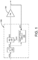
- Fig. 1 illustrates in simplified form a digital predistortion system 100 to compensate for distortion introduced into a transmitted signal by a power amplifier 150.
- the power amplifier 150 is typically most efficient when it is operated in a non-linear range. However, the non-linear response of the power amplifier 150 causes unwanted out-of-band emissions and reduces the spectral efficiency of a communication system.
- the digital predistortion system 100 may be used to improve the efficiency and linearity of the power amplifier 150 by "predistorting" the power amplifier's input signal to compensate for non-linear distortion introduced by the power amplifier 150.
- the digital predistortion system 100 includes an interpolator 110, predistorter 120, and adaptation circuit 130.
- the digital predistortion system 100 may be implemented in one or more processors, hardware, firmware, or a combination thereof.
- An input signal x' ( n ) is input to the interpolator 110.
- the interpolator 110 up-samples the input signal x' ( n ) to increase the sample rate.
- the up-sampled input signal x ( n ) is input into the predistorter 120.
- the predistorter 120 predistorts the input signal x ( n ) to produce a predistorted signal d ( n ) for input to the power amplifier 150.
- the power amplifier 150 After digital-to-analog conversion and filtering, the power amplifier 150 amplifies the predistorted signal to produce an output signal. If the predistorter 120 is properly designed and configured, then the output signal will contain fewer distortion products and out-of-band emissions than if the power amplifier 150 were used alone.
- the predistorted signal x ( n ) is input to the power amplifier 150 and a scaled version of the amplifier output signal y ( n ) is applied to the adaptation circuit 130.
- the purpose of the adaptation circuit 130 is to adapt the coefficients c ( n ), or "parameters,” of the predistorter 120 to minimize distortion in the amplifier output signal.
- the adaptation circuit 130 computes the coefficients c ( n ) used by the predistorter 120 to predistort the input signal.
- the predistorted signal d ( n ) output by the predistorter 120 will have a bandwidth typically three to five times greater than the bandwidth of the original input signal x' ( n ).
- the sampling rate needs to meet the Nyquist criteria. That is, the sampling rate of the input signal x '( n ) needs to be increased to two times the highest frequency component in the predistorted signal d ( n ) .
- FIG. 2 illustrates an exemplary embodiment of the interpolator 110, which up-samples the signal x '( n ) to increase the sample rate.
- the interpolator 110 comprises an up-sampler 112 and a filter 114.
- the up-sampler 112 inserts N-1 zeroes between consecutive samples in the input signal x '( n ) to generate a signal that is N times the received signal.
- the N-1 zeros inserted into the input signal x '( n ) in the time domain create N-1 images of the input signal x '( n ) in the frequency domain.
- the filter 114 filters in the up-sampled input signal x '( n ) to remove the unwanted out-of-band components.
- Figure 3 illustrates the transformations of the input signal x '( n ) in the frequency domain as it passes through the interpolator 150.
- Figure 3A shows the input signal x '( n ) at the sample rate f s-in .
- Figure 3B shows images of the up-sampled signal x '( n ) created by inserting N-1 zeroes into signal x '( n ).
- Figure 3C shows the signal x ( n ) output by the interpolator after filtering.
- the signal x ( n ) has a sample rate that is N times of the received signal x' ( n ) .
- Figure 4 illustrates the bandwidth expansion effect of the predistorter 120.
- Figure 4A illustrates the input signal x ( n ) in the frequency domain, denoted as x ( f ) .
- the input signal x ( f ) has a bandwidth bw.
- Figure 4C illustrates the predistortion introduced by the predistorter 120, which is obtained by subtracting the input signal x ( f ) from the predistorted signal d ( f ).
- the predistorted signal d ( f ) shown in Figure 4B can be divided into two frequency regions, an "input region” and a "shoulder region.”
- the input region (horizontally shaded) comprises the frequency components in the range bw / 2 to -bw / 2.
- the shoulder region (vertically shaded) comprises the frequency components greater than bw / 2 and less than - bw / 2.
- the power level of the frequency components in the input region is typically 30db higher than the power level of the signal in the shoulder region.
- the frequency components in the input region are referred to herein as the "high-dynamic range” components, while the frequency components in the shoulder region are referred to herein as the "low-dynamic range” components.
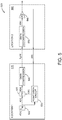
- Figure 5 illustrates in simplified form a wireless communication system 500 including a predistortion subsystem 510 located remotely from a power amplification subsystem 560.
- the power amplification subsystem 560 i.e. "transmitting node”
- the predistortion subsystem 510 includes an up-sampler 520, a digital predistorter 530, a data compressor 540, and an adaptation circuit 550.
- the up-sampler 520, digital predistorter 530 and adaptation circuit 550 operate as previously described.
- the data compressor 540 compresses the predistorted signal output by the digital predistorter 530 to reduce the bandwidth required to transmit the predistorted signal to the power amplification subsystem 560.
- the compressed signal d c ( n ) output by the data compressor 540 is transmitted to the power amplification subsystem 560.
- the power amplification subsystem 560 includes a data decompressor 570 and a power amplifier 580.
- the data decompressor 570 receives the compressed signal d c (n) from the digital predistortion subsystem 510, and decompresses the compressed signal to obtain the predistorted signal d ( n ).
- the predistorted signal d ( n ) is applied to the input of the power amplifier 580.
- the power amplifier 580 amplifies the predistorted signal d ( n ) as previously described to produce an output signal.
- An attenuated version y(n) of the output signal from the power amplification subsystem 560 is fed back to the adaptation circuit 550 in the predistortion subsystem 510.
- the data compressor 540 decomposes the predistorted signal into low-frequency components (shown in Figure 6A as d H (f) in the frequency domain) and high-frequency components (shown in Figure 6B as d ( f )- d H ( f ) in the frequency domain).
- the high-dynamic range components have a higher dynamic range and require more bits to be represented accurately than the low-dynamic range components.
- the highest frequency in the high-dynamic range component is lower than the lowest frequency in the low-dynamic range component, so a lower sample rate can be used for the high-dynamic range components.
- the data compressor 540 takes advantage of these observations by generating a high-dynamic range signal denoted d H ( n ) for the high-dynamic range components and a separate low-dynamic range signal denoted d L ( n ) for the low-dynamic range components. Due to the lower frequency content, the high-dynamic range signal d H ( n ) requires fewer samples to be accurately represented than the low-dynamic range signal d L ( n ) . However, due to the lower dynamic range, the samples of the low-dynamic range signal d L ( n ) require fewer bits. Thus, compression is achieved by both lowering the sample rate of the high-dynamic range signal d H ( n ) and reducing the number of bits in each sample of the low-dynamic range signal d L ( n ) .
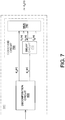
- FIG. 7 illustrates the main functional components of the data compressor 540.
- the data compressor 540 includes a decomposition circuit 600 and a combining circuit 700.
- the decomposition circuit 600 decomposes the input signal into high-dynamic range components and low-dynamic range components, and outputs a high-dynamic range signal d H ( n ) and a low-dynamic range signal d L ( n ) .
- the high-dynamic range signal d H ( n ) has a first sample rate and a first number of bits per sample.
- the low-dynamic range signal has a second sample rate and a second number of bits per sample.
- the sample rate of the low-dynamic range signal d L ( n ) is higher than the sample rate of the high-dynamic range signal, d H ( n ) but uses fewer bits per sample.
- the low-dynamic range signal d L ( n ) and the high-dynamic range signal d H ( n ) are input to the combining circuit 700 for combining prior to transmission.
- the combining circuit 700 includes a tapped delay circuit 710 and a multiplexer 740.
- the tapped delay circuit 710 delays samples of the low-dynamic range signal and outputs l 1 ( n ), l 2 ( n ),..., l N D ( n ).
- the delayed samples are input to multiplexer 740 synchronously with corresponding samples of the high-dynamic range signal d H ( n ) .
- the multiplexer 740 combines each sample of the high-dynamic range signal d H ( n ) with corresponding samples of the low-dynamic range signal d L ( n ) to create a compressed signal d c ( n ) for transmission to the power amplification subsystem 560.
- FIG. 8 illustrates one embodiment of the data compressor 540 in greater detail.
- the decomposition circuit 600 comprises a decimator 610 and an interpolator 640 connected in series.
- the decomposition circuit 600 also includes an optional rate converter 680, a delay circuit 670, and a summer 690.
- the decimator 610 generates the high-dynamic range signal d H ( n ) having a first sample rate.
- the high-dynamic range signal d H ( n ) is then up-sampled by the interpolator 640 and subtracted from the predistorted signal by the summer 690 to generate the low-dynamic range signal d L ( n ) .
- the delay circuit 670 delays the samples of the predistorted signal d ( n ) to match the processing delay of the decimator 610 and interpolator 640.
- the optional rate converter 680 may be used where the sample rate of the predistorted signal d ( n ) is different from the sample rate of the low-dynamic range signal d L ( n ) .
- the decimator 610 includes a low pass filter 620 and down-sampler 630.
- the low pass filter 620 filters the predistorted signal to remove the frequency components in the "shoulder region" to generate a high-dynamic range signal, d H ( n ) .
- the sample rate of the signal output from the low pass filter 620 is higher than need to accurately represent the high-dynamic range signal d H ( n ) .
- the down-sampler 630 reduces the sample rate to the desired sample rate, which is close to the Nyquist rate of the high-dynamic range signal d H ( n ) .
- d H ( n ) is up-sampled by the interpolator 640 to restore the high-dynamic range signal d H ( n ) to the sample rate of the low-dynamic range signal d L ( n ) before being subtracted from the input signal d ( n ).
- the interpolator 640 comprises an up-sampler 650 and low pass filter 660.
- the up-sampler 650 up-samples the high-dynamic range signal output by the decimator 610 and the low pass filter 660 removes unwanted out-of band components.
- the up-sampled high-dynamic range signal is output to the summer 690.
- the interpolator 640 may be configured to up-sample the high-dynamic range signal d H ( n ) to a sample rate different from that of the input signal, in which case the rate converter 680 is needed to match the sample rate of the input signal to the desired sample rate of low-dynamic range signal d L ( n ) before subtraction of the up-sampled high-dynamic range signal d H ⁇ n .
- the summer 690 subtracts the up-sampled high-dynamic range signal d H ⁇ n from the predistorted signal d ( n ) to obtain the low-dynamic range signal d L ( n ), as shown in Figure 8 .
- the delay circuit 670 delays the predistorted signal d ( n ) to account for the processing delay of the decimator 610 and the interpolator 640.
- the delay operation synchronizes the input signal and the up-sampled high-dynamic range signal d H ⁇ n before subtracting the latter from the former to obtain the low-dynamic range signal d L ( n ) .
- the low-dynamic range signal d L ( n ) is then input into the combining circuit 700.
- the combining circuit 700 includes a tapped delay circuit 710 and a multiplexer 740.
- the high-dynamic range signal d H ( n ) is input directly into the multiplexer 740.
- the low-dynamic range signal d L ( n ) is input to the tapped delay circuit 710.
- the tapped delay circuit 710 receives samples of the low-dynamic range signal d L ( n ) output by the summer 690.
- the tapped delay circuit 710 comprises a plurality of delay registers 720 forming a tapped delay line.
- the number of delay registers 720, N L corresponds to the sample rate of the low-dynamic range signal d L ( n ) .
- the samples of the low-dynamic range signal d L ( n ) are shifted one at a time into the tapped delay line.
- Each delay register 720 adds a delay to the sample as it passes through the tapped delay line 720.
- the contents of the delay registers 720 are retrieved synchronously through a set of synchronized switches 730.
- l 1 ( n ), l 2 ( n ),..., l N D ( n ) denote the samples of the low-dynamic range signal d L ( n ) and are expressed as the difference between the signal d ( n ) and d H ( n ) at every sampling time interval, ( N / N')T s-in , where ( N' / N)( 1/ T s-in ) is the sample rate of d H ⁇ n and (1/ T s_in ) is the sample rate of d(n) .
- the multiplexer 740 combines samples of the low-dynamic range signal d L ( n ) with corresponding samples of the high-dynamic range signal d H ( n ) to produce a compressed signal d c ( n ) .
- the multiplexer 740 operates at the sample rate of the high-dynamic range signal d H ( n ) .
- the multiplexer 740 combines the sample of the high-dynamic range signal d H ( n ) with the corresponding samples of the low-dynamic range signal d L ( n ) to generate a compressed predistorted signal d c ( n ), which the data compressor 540 outputs to the power amplification subsystem 570.
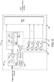
- FIG. 9 illustrates of the main functional components of the power amplification subsystem 560.
- the power amplification subsystem 560 includes a demultiplexer 800, a rate matching circuit 810, a combining circuit 840, an analog power amplifier 580.
- the demultiplexer 800 receives the compressed predistorted signal d c ( n ) as input and demultiplexes the compressed signal back into a high-dynamic range signal d H ( n ) and the low-dynamic range signal d L ( n ) .
- the high-dynamic range signal d H ( n ) from the de-multiplexer 800 may have a different sample rate than that of the predistorted signal d ( n ) .
- the rate matching circuit 810 up-samples the high-dynamic range signal d H ( n ) to the sample rate of the low-dynamic range signal d L ( n ) .
- the up-sampled high-dynamic range signal d H ⁇ ( n ) is then combined with the low-dynamic range signal d L (n) in the combining circuit 840 to obtain the predistorted signal d(n), which after digital-to-analog conversion and filtering is input to the power amplifier 580.
- the data decompressor 570 illustrated in the block diagram of Figure 5 may be realized in different implementations by a person skilled in the art.
- a specific embodiment of the data decompressor 570 is presented in Figure 10 as an example.
- the demultiplexer 800 outputs samples of the high-dynamic range signal d H ( n ) and the low-dynamic range signal d Li ( n ) at a first sample rate equal to the sample rate of the high-dynamic range signal d H ( n ) .
- the samples of high-dynamic range signal are output to the rate matching circuit 810, while the samples of the low-dynamic range signal d L i ( n ) are output to the combining circuit 840.
- the rate matching circuit 810 up-converts the high-dynamic range signal d H ( n ) to match the sample rate of the low-dynamic range signal.
- the rate matching circuit 810 may, for example, comprise an interpolator as previously described and shown in Fig. 2 .
- the rate matching circuit 810 includes an up-sampler 812 to up-sample the high-dynamic range signal d H ( n ) and a low-pass filter 814 to remove unwanted out-of-band components.
- the combining circuit 840 samples of the up-sampled high-dynamic range signal d H ⁇ n are summed with corresponding samples of the low-dynamic range signal d L i ( n ) to form composite samples.
- the combining circuit 840 includes a plurality of summers 850 and a selection circuit 860, which operates at the sample rate of the low-dynamic range signal. During each sampling interval, the rate matching circuit 810 outputs one sample of the up-sampled high-dynamic range signal d H ⁇ n to the combining circuit 840.
- the summers 850 add the sample output by the rate matching circuit 810 with the samples of the low-dynamic range signal d L i ( n ) output by the demultiplexer 800.
- the selection circuit 860 selects one of the combined samples for output to the power amplifier 580.
- the output sequence of the composite signals may be denoted as: d n N N , T s ⁇ in ⁇ 1 N T s ⁇ in , d n N N ' T s ⁇ in ⁇ 2 N T s ⁇ in , d n N N ' T s ⁇ in ⁇ 3 N T s ⁇ in ... d n N N , T s ⁇ in ⁇ N ⁇ 1 N T s ⁇ in , d n ⁇ 1 N N N ' T s ⁇ in ... with T s-in representing the sampling time interval of the predistorted signal output from the predistorter 530.
- Fig. 11 is a flow chart illustrating the data compressing process 900 implemented in the data compressor 540.
- a predistorted signal is decomposed into high-dynamic range components and low-dynamic range components (Step 920).
- a high-dynamic range signal d H ( n ) having a first sample rate is generated.
- the high-dynamic range signal d H ( n ) contains the high-dynamic range components of the predistorted signal.
- a low-dynamic range signal d L ( n ) having a second sample rate is also generated (Step 940).
- the low-dynamic range signal d L ( n ) contains the low-dynamic range components of the predistorted signal.
- samples of the high-dynamic range signal d H ( n ) are combined with corresponding samples of the low-dynamic range signal d L ( n ) (Step 950).
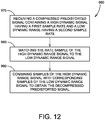
- Fig. 12 is a flow chart illustrating the data decompressing process 960 implemented in the data decompressor 570.
- a compressed predistorted signal is received (Step 970).
- the compressed predistorted signal contains a high-dynamic range signal d H ( n ) having a first sample rate and a low-dynamic range signal d L ( n ) having a second sample rate.
- the sample rate of the high-dynamic range signal d H ( n ) is then converted to match that of the low-dynamic range signal d L ( n ) (Step 980).
- samples of the high and low-dynamic range signals d L ( n ) are combined (Step 990).
- the present invention may be carried out in other specific ways than those herein set forth.
- One or more of the specific processes discussed above may be carried out in a cellular phone or other communications transceiver comprising one or more appropriately configured processing circuits, which may in some embodiments be embodied in one or more application-specific integrated circuits (ASICs).
- these processing circuits may comprise one or more microprocessors, microcontrollers, and/or digital signal processors programmed with appropriate software and/or firmware to carry out one or more of the operations described above, or variants thereof.
- these processing circuits may comprise customized hardware to carry out one or more of the functions described above.
- the present embodiments are, therefore, to be considered in all respects as illustrative and not restrictive, and all changes coming within the scope of the appended claims are intended to be embraced.
Landscapes
- Engineering & Computer Science (AREA)
- Power Engineering (AREA)
- Signal Processing (AREA)
- Computer Networks & Wireless Communication (AREA)
- Physics & Mathematics (AREA)
- Nonlinear Science (AREA)
- Microelectronics & Electronic Packaging (AREA)
- Computer Security & Cryptography (AREA)
- Theoretical Computer Science (AREA)
- Multimedia (AREA)
- Amplifiers (AREA)
Claims (15)
- Verfahren (900) zum Komprimieren eines vorverzerrten Signals (d(n)) zur Übertragung von einem Verarbeitungsknoten an einen Remote-Knoten, wobei das Verfahren Folgendes umfasst:Zersetzen (920) des vorverzerrten Signals (d(n)) in niederfrequente Komponenten (dH(f)) in einem ersten Frequenzbereich, der dem eines Eingangssignals (x(n)) entspricht, das in einen Vorverzerrer (530) eingegeben wurde, um das vorverzerrte Signal (d(n)) zu produzieren, und in hochfrequente Komponenten (d(f)-(dH(f)) in einem zweiten Frequenzbereich mit höherem Frequenzgehalt des vorverzerrten Signals (d(n)) als der erste Bereich;Erzeugen (930) eines hochdynamischen Reichweitensignals (dH(n)), das eine erste Abtastrate aufweist und die niederfrequenten Komponenten (dH(f)) enthält;Erzeugen (940) eines niederdynamischen Reichweitensignals (dL(n)) mit einer zweiten Abtastrate, die größer ist als die erste Abtastrate, mit Abtastungen, die weniger Bits benötigen als die Abtastungen des hochdynamischen Reichweitensignals und die die hochfrequenten Komponenten (d(f)-dH(f)) enthält; undKombinieren (950) von Abtastungen des hochdynamischen Reichweitensignals (dH(n)) mit entsprechenden Abtastungen des niederdynamischen Reichweitensignals (dL(n)), um ein komprimiertes Signal (dC(n)) zur Übertragung an den Remote-Knoten zu produzieren.
- Verfahren (900) nach Anspruch 1, wobei das Zersetzen (920) des vorverzerrten Signals (d(n)) Folgendes umfasst:
Entfernen der hochfrequenten Komponenten (d(f)-dH(f)) des vorverzerrten Signals (d(n)), um das hochdynamische Reichweitensignal (dH(n)) zu erhalten; und
Subtrahieren des hochdynamischen Reichweitensignals (dH(n)) von dem vorverzerrten Signal (d(n)), um das niederdynamische Reichweitensignal (dL(n)) zu erhalten, wobei das Entfernen der hochfrequenten Komponenten (d(f)-dH(f)) des vorverzerrten Signals (d(n)) ein Filtern des vorverzerrten Signals (d(n)) umfasst, wobei das Erzeugen des hochdynamischen Reichweitensignals (dH(n)) mit der ersten Abtastrate ein Dezimieren des hochdynamischen Signals, das durch das Filtern erzeugt wurde, umfasst. - Verfahren (900) nach einem der Ansprüche 1 und 2, wobei ein Erzeugen des niederdynamischen Reichweitensignals (dL(n)) an der zweiten Abtastrate Folgendes umfasst:
Interpolieren des hochdynamischen Reichweitensignals (dH(n)), um eine hochgetastete Version des hochdynamischen Reichweitensignals zu erhalten; und
Subtrahieren der hochgetasteten Version des hochdynamischen Reichweitensignals von dem vorverzerrten Signal (d(n)), um das niederdynamische Reichweitensignal (dL(n)) mit der zweiten Abtastrate zu erhalten, wobei das Verfahren optional ferner ein Verändern der Abtastrate des vorverzerrten Signals (d(n)) umfasst, um mit dem hochdynamischen Reichweitensignal (dH(n)) übereinzustimmen, bevor die hochgetastete Version des hochdynamischen Reichweitensignals subtrahiert wird. - Verfahren (900) nach einem der Ansprüche 1 bis 3, wobei das Kombinieren von Abtastungen des hochdynamischen Reichweitensignals (dH(n)) mit entsprechenden Abtastungen des niederdynamischen Reichweitensignals (dL(n)), um ein komprimiertes Signal (dC(n)) zur Übertragung an den Remote-Knoten zu erzeugen, Folgendes umfasst:Verzögern von Abtastungen des niederdynamischen Reichweitensignals (dL(n)) in einer angezapften Verzögerungsleitung (710), die eine Vielzahl von Verzögerungsregistern (720) beinhaltet; undregelmäßiges Kombinieren von Abtastungen des niederdynamischen Reichweitensignals (dL(n)) in den Verzögerungsregistern (720) mit einer entsprechenden Abtastung des hochdynamischen Reichweitensignals (dH(n)), wobei das regelmäßige Kombinieren von Abtastungen des niederdynamischen Reichweitensignals (dL(n)) in den Verzögerungsregistern (720) mit einer entsprechenden Abtastung des hochdynamischen Reichweitensignals (dH(n)) Folgendes umfasst:Multiplexen der Abtastung des hochdynamischen Reichweitensignals (dH(n)) mit den entsprechenden Abtastungen des niederdynamischen Reichweitensignals (dL(n)), um das komprimierte Signal (dC(n)) zu erhalten.Eingeben, in einen Multiplexer (740), einer Abtastung des hochdynamischen Reichweitensignals (dH(n));Eingeben, in den Multiplexer (740), von Abtastungen des niederdynamischen Reichweitensignals (dL(n)) in den Verzögerungsregistern (720) gleichzeitig mit der Abtastung des hochdynamischen Reichweitensignals (dH(n)); und
- Datenkomprimierungsschaltung (540) zum Komprimieren eines vorverzerrten Signals (d(n)) zur Übertragung von einem Verarbeitungsknoten an einen Remote-Knoten, wobei die Datenkomprimierungsschaltung (540) Folgendes umfasst:eine Zersetzungsschaltung (600), konfiguriert zum:Zersetzen (920) des vorverzerrten Signals (d(n)) in niederfrequente Komponenten (dH(f)) in einem ersten Frequenzbereich, der dem eines Eingangssignals (x(n)) entspricht, das in einen Vorverzerrer (530) eingegeben wurde, um das vorverzerrte Signal (d(n)) zu erzeugen, und in hochfrequente Komponenten (d(f)-(dH(f)) in einem zweiten Frequenzbereich mit höherem Frequenzgehalt des vorverzerrten Signals (d(n)) als der erste Bereich;Erzeugen (930) eines hochdynamischen Reichweitensignals (dH(n)), das eine erste Abtastrate für die niederfrequenten Komponenten (dH(f)) aufweist;Erzeugen (940) eines niederdynamischen Reichweitensignals (dL(n)) mit einer zweiten Abtastrate für die hochfrequenten Komponenten (d(f)-dH(f)), wobei die zweite Abtastrate größer ist als die erste Abtastrate und Abtastungen aufweist, die weniger Bits benötigen als die Abtastungen des hochdynamischen Reichweitensignals; undeine Kombinierungsschaltung (700) zum Kombinieren von Abtastungen des hochdynamischen Reichweitensignals (dH(n)) mit entsprechenden Abtastungen des niederdynamischen Reichweitensignals (dL(n)), um ein komprimiertes Signal (dC(n)) zur Übertragung an den Remote-Knoten zu produzieren.
- Datenkomprimierungsschaltung (540) nach Anspruch 5, wobei das Zersetzen des vorverzerrten Signals (d(n)) Folgendes umfasst:Entfernen der hochfrequenten Komponenten (d(f)-dH(f)) des vorverzerrten Signals (d(n)), um das hochdynamische Reichweitensignal (dH(n)) zu erhalten; undSubtrahieren des hochdynamischen Reichweitensignals (dH(n)) von dem vorverzerrten Signal (d(n)), um das niederdynamische Reichweitensignal (dL(n)) zu erhalten;und wobei die Datenkomprimierungsschaltung (540) einen Filter (620) umfasst, um die hochfrequenten Komponenten (d(f)-dH(f)) des vorverzerrten Signals (d(n)) zu entfernen, um ein gefiltertes Signal mit niederfrequenten Komponenten (dH(f)) zu erzeugen, wobei die Datenkomprimierungsschaltung (540) eine abwärtstastende Schaltung (630) umfasst, um das gefilterte Signal, das von dem Filter (620) ausgegeben wurde, abwärts abzutasten, um das hochdynamische Reichweitensignal (dH(n)) mit der ersten Abtastrate zu erzeugen.
- Datenkomprimierungsschaltung (540) nach einem der Ansprüche 5 und 6, wobei die Datenkomprimierungsschaltung Folgendes umfasst:einen Interpolator (640), um das hochdynamische Reichweitensignal (dH(n)) hochzutasten; undeinen Subtrahierer (690), um die hochgetastete Version des hochdynamischen Reichweitensignals von dem vorverzerrten Signal (d(n)) zu subtrahieren, um das niederdynamische Reichweitensignal (dL(n)) mit der zweiten Abtastrate zu erhalten;wobei die Datenkomprimierungsschaltung (540) ferner einen Abtastraten-Wandler (680) umfasst, um die Abtastrate des vorverzerrten Signals (d(n)) zu variieren, um mit dem hochdynamischen Reichweitensignal (dH(n)) übereinzustimmen, bevor die hochgetastete Version des hochdynamischen Reichweitensignals subtrahiert wird.
- Datenkomprimierungsschaltung (540) nach einem der Ansprüche 5 bis 7, wobei die Kombinierungsschaltung (700) Folgendes umfasst:eine Verzögerungsschaltung (710), um Abtastungen des niederdynamischen Reichweitensignals (dL(n)) zu verzögern; undeinen Multiplexer (740), um Abtastungen des niederdynamischen Reichweitensignals (dL(n)) in der Verzögerungsschaltung (710) regelmäßig mit einer entsprechenden Abtastung des hochdynamischen Reichweitensignals (dH(n)) zu kombinieren; undwobei die Verzögerungsschaltung (710) Folgendes umfasst:eine angezapfte Verzögerungsleitung (710) mit einer Vielzahl von Verzögerungsregistern (720) zum Verzögern der Abtastungen des niederdynamischen Reichweitensignals (dL(n));eine Reihe von Schaltern (730), um Abtastungen des niederdynamischen Reichweitensignals (dL(n)) in den Verzögerungsregistern (720) gleichzeitig mit entsprechenden Abtastungen des hochdynamischen Reichweitensignals (dH(n)) an den Multiplexer (740) auszugeben.
- Datenkomprimierungsschaltung (540) nach einem der Ansprüche 5 bis 8, ferner umfassend einen Sender, um das komprimierte Signal (dC(n)) an den Remote-Knoten zu übertragen.
- Verfahren (960) zum Dekomprimieren eines komprimierten vorverzerrten Signals (dC(n)), das von einem Verarbeitungsknoten empfangen wurde, wobei das Verfahren Folgendes umfasst:Empfangen (970) eines komprimierten vorverzerrten Signals (dC(n)), wobei das komprimierte vorverzerrte Signal (dC(n)) Abtastungen von einem hochdynamischen Reichweitensignal (dH(n)) beinhaltet, das eine erste Abtastrate aufweist und niederfrequente Komponenten (dH(f)) eines vorverzerrten Signals (d(n)) in einem ersten Frequenzbereich enthält, der dem eines Eingangssignals (x(n)) entspricht, das in einen Vorverzerrer (530) eingegeben wurde, um das vorverzerrte Signal (d(n)) zu produzieren, und wobei das komprimierte vorverzerrte Signal (dC (n)) Abtastungen von einem niederdynamischen Reichweitensignal (dL(n)) beinhaltet, wobei die Abtastungen weniger Bits benötigen als die Abtastungen von dem hochdynamischen Reichweitensignal, wobei das niederdynamische Reichweitensignal eine zweite Abtastrate aufweist und hochfrequente Komponenten (d(f)-dH(f)) in einem zweiten Frequenzbereich enthält, der einen höheren Frequenzgehalt des vorverzerrten Signals (d(n)) aufweist als der erste Bereich;Angleichen (980) der Abtastrate des hochdynamischen Reichweitensignals (dH(n)) an die Abtastrate des niederdynamischen Reichweitensignals (dL(n)); undKombinieren (990) von Abtastungen des hochdynamischen Reichweitensignals (dH(n)) mit entsprechenden Abtastungen des niederdynamischen Reichweitensignals (dL(n)), um das dekomprimierte vorverzerrte Signal (d(n)) zu erhalten.
- Verfahren (960) nach Anspruch 10, wobei das Angleichen der Abtastrate des hochdynamischen Reichweitensignals (dH(n)) an die Abtastrate des niederdynamischen Reichweitensignals (dL(n)) ein Hochtasten des hochdynamischen Reichweitensignals (dH(n)) umfasst, um die Abtastrate des niederdynamischen Reichweitensignals (dL(n)) anzugleichen, wobei das Verfahren ferner das Filtern des hochdynamischen Reichweitensignals nach dem Hochtasten des hochdynamischen Reichweitensignals (dH(n)) umfasst, um Komponenten außerhalb des Bandes zu entfernen.
- Verfahren (960) nach einem der Ansprüche 10 und 11, wobei das Kombinieren von Abtastungen des hochdynamischen Reichweitensignals (dH(n)) mit entsprechenden Abtastungen des niederdynamischen Reichweitensignals (dL(n)) Folgendes umfasst:Summieren von Abtastungen des hochdynamischen Reichweitensignals (dH(n)) mit entsprechenden Abtastungen des niederdynamischen Reichweitensignals (dL(n)), um zusammengesetzte Abtastungen zu erzeugen; undsequentielles Ausgeben der zusammengesetzten Abtastungen, um das dekomprimierte vorverzerrte Signal (d(n)) zu erzeugen.
- Dekomprimierer (570) zum Dekomprimieren eines komprimierten vorverzerrten Signals (dC(n)), wobei der Dekomprimierer (570) Folgendes umfasst:eine Eingabe (800) zum Empfangen eines komprimierten vorverzerrten Signals (dC(n)), wobei das komprimierte vorverzerrte Signal (dC(n)) Abtastungen von einem hochdynamischen Reichweitensignal (dH(n)) beinhaltet, das eine erste Abtastrate aufweist und niederfrequente Komponenten (dH(f)) eines vorverzerrten Signals (d(n)) in einem ersten Frequenzbereich enthält, der dem eines Eingangssignals (x(n)) entspricht, das in einen Vorverzerrer (530) eingegeben wurde, um das vorverzerrte Signal (d(n)) zu produzieren, und wobei das komprimierte vorverzerrte Signal (dC (n)) Abtastungen von einem niederdynamischen Reichweitensignal (dL(n)) beinhaltet, wobei die Abtastungen weniger Bits benötigen als die Abtastungen von dem hochdynamischen Reichweitensignal, wobei das niederdynamische Reichweitensignal eine zweite Abtastrate aufweist, die größer ist als die erste Abtastrate und hochfrequente Komponenten (d(f)-dH(f)) in einem zweiten Frequenzbereich enthält, der höheren Frequenzgehalt des vorverzerrten Signals (d(n)) aufweist als der erste Bereich;eine Ratenanpassungsschaltung (810) zum Anpassen der ersten Abtastrate des hochdynamischen Reichweitensignals (dH(n)) an die zweite Abtastrate des niederdynamischen Reichweitensignals (dL(n)); undeine Kombinierungsschaltung (840) zum Kombinieren von Abtastungen des hochdynamischen Reichweitensignals (dH(n)) mit entsprechenden Abtastungen des niederdynamischen Reichweitensignals (dL(n)), um ein dekomprimiertes vorverzerrtes Signal (d(n)) zu erhalten.
- Dekomprimierer (570) nach Anspruch 13, wobei die Ratenanpassungsschaltung (810) einen Interpolator (110) umfasst, um das hochdynamische Reichweitensignal (dH(n)) hochzutasten, um es der Abtastrate des niederdynamischen Reichweitensignals (dL(n)) anzupassen, wobei der Interpolator (110) einen Filter (114) beinhaltet, um Komponenten außerhalb des Bandes von dem hochgetasteten hochdynamischen Reichweitensignal zu entfernen.
- Dekomprimierer (570) nach einem der Ansprüche 13 und 14, wobei die Kombinierungsschaltung (840) Folgendes umfasst:eine Summierungsschaltung (850) zum Summieren von Abtastungen des hochdynamischen Reichweitensignals (dH(n)) mit entsprechenden Abtastungen des niederdynamischen Reichweitensignals (dL(n)), um zusammengesetzte Abtastungen zu erzeugen; undeinen Auswähler (860) zum sequentiellen Ausgeben der zusammengesetzten Abtastungen, um das dekomprimierte vorverzerrte Signal (d(n)) zu erzeugen.
Applications Claiming Priority (2)
| Application Number | Priority Date | Filing Date | Title |
|---|---|---|---|
| US201261611355P | 2012-03-15 | 2012-03-15 | |
| PCT/IB2012/001811 WO2013136109A1 (en) | 2012-03-15 | 2012-07-19 | Method of transmitting data samples with reduced bandwidth |
Publications (2)
| Publication Number | Publication Date |
|---|---|
| EP2847762A1 EP2847762A1 (de) | 2015-03-18 |
| EP2847762B1 true EP2847762B1 (de) | 2018-05-09 |
Family
ID=47010644
Family Applications (1)
| Application Number | Title | Priority Date | Filing Date |
|---|---|---|---|
| EP12770216.5A Active EP2847762B1 (de) | 2012-03-15 | 2012-07-19 | Verfahren zur übertragung von datenproben mit verminderter bandbreite |
Country Status (4)
| Country | Link |
|---|---|
| US (2) | US8761241B2 (de) |
| EP (1) | EP2847762B1 (de) |
| CN (1) | CN104170008B (de) |
| WO (1) | WO2013136109A1 (de) |
Families Citing this family (13)
| Publication number | Priority date | Publication date | Assignee | Title |
|---|---|---|---|---|
| GB2495066B (en) | 2010-07-26 | 2013-12-18 | Seven Networks Inc | Mobile application traffic optimization |
| WO2013015835A1 (en) | 2011-07-22 | 2013-01-31 | Seven Networks, Inc. | Mobile application traffic optimization |
| US9014241B2 (en) * | 2012-11-12 | 2015-04-21 | Xilinx, Inc. | Digital pre-distortion in a communication network |
| WO2014172386A2 (en) * | 2013-04-15 | 2014-10-23 | Seven Networks, Inc. | Temporary or partial offloading of mobile applicaton functions to a cloud-based environment |
| WO2016033599A1 (en) | 2014-08-29 | 2016-03-03 | Cardioinsight Technologies, Inc. | Localization and tracking of an object |
| US20160080778A1 (en) * | 2014-09-11 | 2016-03-17 | Gatesair, Inc. | Hybrid modulator utilizing digital domain multiplexing |
| JP2019176205A (ja) * | 2018-03-26 | 2019-10-10 | 古河電気工業株式会社 | 増幅装置 |
| US11003205B2 (en) * | 2019-02-04 | 2021-05-11 | Sigmasense, Llc. | Receive analog to digital circuit of a low voltage drive circuit data communication system |
| CN111162884A (zh) * | 2018-11-07 | 2020-05-15 | 中国电信股份有限公司 | 信道优化方法和装置 |
| US10715702B1 (en) * | 2019-03-12 | 2020-07-14 | Xilinx, Inc. | Method of and circuit for predistortion for a cable TV amplifier |
| JP7577762B2 (ja) * | 2020-06-03 | 2024-11-05 | ドルビー ラボラトリーズ ライセンシング コーポレイション | Hdrコンテンツを編集するための動的メタデータの計算 |
| CN112037781B (zh) * | 2020-08-07 | 2024-01-19 | 北京百度网讯科技有限公司 | 语音数据的获取方法和装置 |
| CN118138410A (zh) * | 2022-12-02 | 2024-06-04 | 中兴通讯股份有限公司 | 数字预失真处理方法、装置、终端设备及计算机存储介质 |
Family Cites Families (10)
| Publication number | Priority date | Publication date | Assignee | Title |
|---|---|---|---|---|
| GB8518803D0 (en) | 1985-07-25 | 1985-08-29 | Rca Corp | Locating target patterns within images |
| US5978518A (en) * | 1997-02-25 | 1999-11-02 | Eastman Kodak Company | Image enhancement in digital image processing |
| JP2001007769A (ja) * | 1999-04-22 | 2001-01-12 | Matsushita Electric Ind Co Ltd | 低遅延サブバンド分割/合成装置 |
| EP1104101A3 (de) * | 1999-11-26 | 2005-02-02 | Matsushita Electric Industrial Co., Ltd. | Vorrichtung zur Teilbandtrennung / Zusammensetzung eines digitalen Signal zur erzeugung einer Filterung mit Bandtrennung und Bandzusammensetzung mit verringerten Gruppenlaufzeit |
| US7260523B2 (en) * | 1999-12-21 | 2007-08-21 | Texas Instruments Incorporated | Sub-band speech coding system |
| DE60335977D1 (de) * | 2002-09-27 | 2011-03-24 | Broadcom Corp | Splitter und Kombinierer in einem Kommunikationssystem mit mehrfachen Datenraten |
| KR100546685B1 (ko) * | 2003-12-17 | 2006-01-26 | 엘지전자 주식회사 | 통신 시스템의 호 접속률 향상 방법 및 그를 위한 장치 |
| WO2010102441A1 (en) * | 2009-03-09 | 2010-09-16 | Zte Wistron Telecom Ab | Method and apparatus for linearizing a non-linear power amplifier |
| US20120328050A1 (en) | 2011-06-21 | 2012-12-27 | Telefonaktiebolaget L M Ericsson (Publ) | Centralized adaptor architecture for power amplifier linearizations in advanced wireless communication systems |
| US8599050B2 (en) * | 2012-01-06 | 2013-12-03 | Maxlinear, Inc. | Method and system for broadband analog to digital converter technology |
-
2012
- 2012-07-19 EP EP12770216.5A patent/EP2847762B1/de active Active
- 2012-07-19 WO PCT/IB2012/001811 patent/WO2013136109A1/en not_active Ceased
- 2012-07-19 CN CN201280071443.9A patent/CN104170008B/zh not_active Expired - Fee Related
- 2012-07-19 US US13/553,014 patent/US8761241B2/en active Active
-
2014
- 2014-05-20 US US14/282,032 patent/US9166840B2/en active Active
Also Published As
| Publication number | Publication date |
|---|---|
| WO2013136109A1 (en) | 2013-09-19 |
| US20140254656A1 (en) | 2014-09-11 |
| US20130243074A1 (en) | 2013-09-19 |
| CN104170008B (zh) | 2018-02-27 |
| EP2847762A1 (de) | 2015-03-18 |
| US9166840B2 (en) | 2015-10-20 |
| CN104170008A (zh) | 2014-11-26 |
| US8761241B2 (en) | 2014-06-24 |
Similar Documents
| Publication | Publication Date | Title |
|---|---|---|
| EP2847762B1 (de) | Verfahren zur übertragung von datenproben mit verminderter bandbreite | |
| US7619487B2 (en) | Polar modulation without analog filtering | |
| KR20190121825A (ko) | 멀티밴드 디지털 전치왜곡기 | |
| KR100921905B1 (ko) | 부분 복소 변조 필터 뱅크 | |
| US6298097B1 (en) | Amplifier with wideband digital predistortion | |
| US9705477B2 (en) | Compensator for removing nonlinear distortion | |
| EP3005553B1 (de) | Mehrbandige digitale hochfrequenz-vorverzerrung | |
| US8488656B2 (en) | Oversampled synthesizer systems and methods | |
| US7372907B2 (en) | Efficient and flexible oversampled filterbank with near perfect reconstruction constraint | |
| KR100799406B1 (ko) | 대역 내 신호의 감쇠를 보상하기 위한 디지털 샘플링레이트 변환기 | |
| EP3676958A1 (de) | Verfahren und vorrichtung zur digitalen vorverzerrung mit verringertem überabtastungsausgangsverhältnis | |
| EP2870693A2 (de) | Adaptionsschema mit niedriger abtastrate für dualband-linearisierung | |
| US20040217891A1 (en) | Analog reconstruction of a digital signal | |
| EP1992073A2 (de) | Reduktion des verhältnisses der spitzen- zur mittelleistung eines signals | |
| US20140266820A1 (en) | Interleaved multipath digital power amplification | |
| EP2161841B1 (de) | Vorverzerrung eines Hochfrequenzsignals | |
| US9595925B2 (en) | Distortion-compensating power amplifier and method for compensating for distortion to amplify power | |
| JP5870739B2 (ja) | プリディストーション装置 | |
| KR20170083819A (ko) | 데이터 압축 복원 장치 및 그 동작 방법 | |
| Cheng et al. | Blind Compensation Method for Concurrent Dual-Band RF Receiver Based on Sparsity | |
| US7586428B2 (en) | Non-linear processing of signals | |
| AU2015210385B2 (en) | Apparatus and Method for Processing an Audio Signal |
Legal Events
| Date | Code | Title | Description |
|---|---|---|---|
| PUAI | Public reference made under article 153(3) epc to a published international application that has entered the european phase |
Free format text: ORIGINAL CODE: 0009012 |
|
| 17P | Request for examination filed |
Effective date: 20141007 |
|
| AK | Designated contracting states |
Kind code of ref document: A1 Designated state(s): AL AT BE BG CH CY CZ DE DK EE ES FI FR GB GR HR HU IE IS IT LI LT LU LV MC MK MT NL NO PL PT RO RS SE SI SK SM TR |
|
| AX | Request for extension of the european patent |
Extension state: BA ME |
|
| DAX | Request for extension of the european patent (deleted) | ||
| GRAP | Despatch of communication of intention to grant a patent |
Free format text: ORIGINAL CODE: EPIDOSNIGR1 |
|
| STAA | Information on the status of an ep patent application or granted ep patent |
Free format text: STATUS: GRANT OF PATENT IS INTENDED |
|
| RIC1 | Information provided on ipc code assigned before grant |
Ipc: G10L 19/02 20130101AFI20180202BHEP Ipc: H03M 7/30 20060101ALI20180202BHEP |
|
| INTG | Intention to grant announced |
Effective date: 20180301 |
|
| GRAS | Grant fee paid |
Free format text: ORIGINAL CODE: EPIDOSNIGR3 |
|
| GRAA | (expected) grant |
Free format text: ORIGINAL CODE: 0009210 |
|
| STAA | Information on the status of an ep patent application or granted ep patent |
Free format text: STATUS: THE PATENT HAS BEEN GRANTED |
|
| AK | Designated contracting states |
Kind code of ref document: B1 Designated state(s): AL AT BE BG CH CY CZ DE DK EE ES FI FR GB GR HR HU IE IS IT LI LT LU LV MC MK MT NL NO PL PT RO RS SE SI SK SM TR |
|
| REG | Reference to a national code |
Ref country code: GB Ref legal event code: FG4D |
|
| REG | Reference to a national code |
Ref country code: CH Ref legal event code: EP Ref country code: AT Ref legal event code: REF Ref document number: 998255 Country of ref document: AT Kind code of ref document: T Effective date: 20180515 |
|
| REG | Reference to a national code |
Ref country code: IE Ref legal event code: FG4D |
|
| REG | Reference to a national code |
Ref country code: DE Ref legal event code: R096 Ref document number: 602012046198 Country of ref document: DE |
|
| REG | Reference to a national code |
Ref country code: FR Ref legal event code: PLFP Year of fee payment: 7 |
|
| REG | Reference to a national code |
Ref country code: NL Ref legal event code: MP Effective date: 20180509 |
|
| REG | Reference to a national code |
Ref country code: LT Ref legal event code: MG4D |
|
| PG25 | Lapsed in a contracting state [announced via postgrant information from national office to epo] |
Ref country code: SE Free format text: LAPSE BECAUSE OF FAILURE TO SUBMIT A TRANSLATION OF THE DESCRIPTION OR TO PAY THE FEE WITHIN THE PRESCRIBED TIME-LIMIT Effective date: 20180509 Ref country code: LT Free format text: LAPSE BECAUSE OF FAILURE TO SUBMIT A TRANSLATION OF THE DESCRIPTION OR TO PAY THE FEE WITHIN THE PRESCRIBED TIME-LIMIT Effective date: 20180509 Ref country code: ES Free format text: LAPSE BECAUSE OF FAILURE TO SUBMIT A TRANSLATION OF THE DESCRIPTION OR TO PAY THE FEE WITHIN THE PRESCRIBED TIME-LIMIT Effective date: 20180509 Ref country code: NO Free format text: LAPSE BECAUSE OF FAILURE TO SUBMIT A TRANSLATION OF THE DESCRIPTION OR TO PAY THE FEE WITHIN THE PRESCRIBED TIME-LIMIT Effective date: 20180809 Ref country code: FI Free format text: LAPSE BECAUSE OF FAILURE TO SUBMIT A TRANSLATION OF THE DESCRIPTION OR TO PAY THE FEE WITHIN THE PRESCRIBED TIME-LIMIT Effective date: 20180509 Ref country code: BG Free format text: LAPSE BECAUSE OF FAILURE TO SUBMIT A TRANSLATION OF THE DESCRIPTION OR TO PAY THE FEE WITHIN THE PRESCRIBED TIME-LIMIT Effective date: 20180809 |
|
| PG25 | Lapsed in a contracting state [announced via postgrant information from national office to epo] |
Ref country code: GR Free format text: LAPSE BECAUSE OF FAILURE TO SUBMIT A TRANSLATION OF THE DESCRIPTION OR TO PAY THE FEE WITHIN THE PRESCRIBED TIME-LIMIT Effective date: 20180810 Ref country code: HR Free format text: LAPSE BECAUSE OF FAILURE TO SUBMIT A TRANSLATION OF THE DESCRIPTION OR TO PAY THE FEE WITHIN THE PRESCRIBED TIME-LIMIT Effective date: 20180509 Ref country code: NL Free format text: LAPSE BECAUSE OF FAILURE TO SUBMIT A TRANSLATION OF THE DESCRIPTION OR TO PAY THE FEE WITHIN THE PRESCRIBED TIME-LIMIT Effective date: 20180509 Ref country code: RS Free format text: LAPSE BECAUSE OF FAILURE TO SUBMIT A TRANSLATION OF THE DESCRIPTION OR TO PAY THE FEE WITHIN THE PRESCRIBED TIME-LIMIT Effective date: 20180509 Ref country code: LV Free format text: LAPSE BECAUSE OF FAILURE TO SUBMIT A TRANSLATION OF THE DESCRIPTION OR TO PAY THE FEE WITHIN THE PRESCRIBED TIME-LIMIT Effective date: 20180509 |
|
| REG | Reference to a national code |
Ref country code: AT Ref legal event code: MK05 Ref document number: 998255 Country of ref document: AT Kind code of ref document: T Effective date: 20180509 |
|
| PG25 | Lapsed in a contracting state [announced via postgrant information from national office to epo] |
Ref country code: AT Free format text: LAPSE BECAUSE OF FAILURE TO SUBMIT A TRANSLATION OF THE DESCRIPTION OR TO PAY THE FEE WITHIN THE PRESCRIBED TIME-LIMIT Effective date: 20180509 Ref country code: EE Free format text: LAPSE BECAUSE OF FAILURE TO SUBMIT A TRANSLATION OF THE DESCRIPTION OR TO PAY THE FEE WITHIN THE PRESCRIBED TIME-LIMIT Effective date: 20180509 Ref country code: DK Free format text: LAPSE BECAUSE OF FAILURE TO SUBMIT A TRANSLATION OF THE DESCRIPTION OR TO PAY THE FEE WITHIN THE PRESCRIBED TIME-LIMIT Effective date: 20180509 Ref country code: SK Free format text: LAPSE BECAUSE OF FAILURE TO SUBMIT A TRANSLATION OF THE DESCRIPTION OR TO PAY THE FEE WITHIN THE PRESCRIBED TIME-LIMIT Effective date: 20180509 Ref country code: RO Free format text: LAPSE BECAUSE OF FAILURE TO SUBMIT A TRANSLATION OF THE DESCRIPTION OR TO PAY THE FEE WITHIN THE PRESCRIBED TIME-LIMIT Effective date: 20180509 Ref country code: CZ Free format text: LAPSE BECAUSE OF FAILURE TO SUBMIT A TRANSLATION OF THE DESCRIPTION OR TO PAY THE FEE WITHIN THE PRESCRIBED TIME-LIMIT Effective date: 20180509 Ref country code: PL Free format text: LAPSE BECAUSE OF FAILURE TO SUBMIT A TRANSLATION OF THE DESCRIPTION OR TO PAY THE FEE WITHIN THE PRESCRIBED TIME-LIMIT Effective date: 20180509 |
|
| REG | Reference to a national code |
Ref country code: DE Ref legal event code: R097 Ref document number: 602012046198 Country of ref document: DE |
|
| PG25 | Lapsed in a contracting state [announced via postgrant information from national office to epo] |
Ref country code: IT Free format text: LAPSE BECAUSE OF FAILURE TO SUBMIT A TRANSLATION OF THE DESCRIPTION OR TO PAY THE FEE WITHIN THE PRESCRIBED TIME-LIMIT Effective date: 20180509 Ref country code: SM Free format text: LAPSE BECAUSE OF FAILURE TO SUBMIT A TRANSLATION OF THE DESCRIPTION OR TO PAY THE FEE WITHIN THE PRESCRIBED TIME-LIMIT Effective date: 20180509 |
|
| REG | Reference to a national code |
Ref country code: CH Ref legal event code: PL |
|
| PLBE | No opposition filed within time limit |
Free format text: ORIGINAL CODE: 0009261 |
|
| STAA | Information on the status of an ep patent application or granted ep patent |
Free format text: STATUS: NO OPPOSITION FILED WITHIN TIME LIMIT |
|
| PG25 | Lapsed in a contracting state [announced via postgrant information from national office to epo] |
Ref country code: LU Free format text: LAPSE BECAUSE OF NON-PAYMENT OF DUE FEES Effective date: 20180719 Ref country code: MC Free format text: LAPSE BECAUSE OF FAILURE TO SUBMIT A TRANSLATION OF THE DESCRIPTION OR TO PAY THE FEE WITHIN THE PRESCRIBED TIME-LIMIT Effective date: 20180509 |
|
| REG | Reference to a national code |
Ref country code: BE Ref legal event code: MM Effective date: 20180731 |
|
| 26N | No opposition filed |
Effective date: 20190212 |
|
| REG | Reference to a national code |
Ref country code: IE Ref legal event code: MM4A |
|
| PG25 | Lapsed in a contracting state [announced via postgrant information from national office to epo] |
Ref country code: CH Free format text: LAPSE BECAUSE OF NON-PAYMENT OF DUE FEES Effective date: 20180731 Ref country code: LI Free format text: LAPSE BECAUSE OF NON-PAYMENT OF DUE FEES Effective date: 20180731 Ref country code: IE Free format text: LAPSE BECAUSE OF NON-PAYMENT OF DUE FEES Effective date: 20180719 |
|
| PG25 | Lapsed in a contracting state [announced via postgrant information from national office to epo] |
Ref country code: BE Free format text: LAPSE BECAUSE OF NON-PAYMENT OF DUE FEES Effective date: 20180731 Ref country code: SI Free format text: LAPSE BECAUSE OF FAILURE TO SUBMIT A TRANSLATION OF THE DESCRIPTION OR TO PAY THE FEE WITHIN THE PRESCRIBED TIME-LIMIT Effective date: 20180509 |
|
| PG25 | Lapsed in a contracting state [announced via postgrant information from national office to epo] |
Ref country code: AL Free format text: LAPSE BECAUSE OF FAILURE TO SUBMIT A TRANSLATION OF THE DESCRIPTION OR TO PAY THE FEE WITHIN THE PRESCRIBED TIME-LIMIT Effective date: 20180509 |
|
| PG25 | Lapsed in a contracting state [announced via postgrant information from national office to epo] |
Ref country code: MT Free format text: LAPSE BECAUSE OF NON-PAYMENT OF DUE FEES Effective date: 20180719 |
|
| PG25 | Lapsed in a contracting state [announced via postgrant information from national office to epo] |
Ref country code: TR Free format text: LAPSE BECAUSE OF FAILURE TO SUBMIT A TRANSLATION OF THE DESCRIPTION OR TO PAY THE FEE WITHIN THE PRESCRIBED TIME-LIMIT Effective date: 20180509 |
|
| PG25 | Lapsed in a contracting state [announced via postgrant information from national office to epo] |
Ref country code: PT Free format text: LAPSE BECAUSE OF FAILURE TO SUBMIT A TRANSLATION OF THE DESCRIPTION OR TO PAY THE FEE WITHIN THE PRESCRIBED TIME-LIMIT Effective date: 20180509 Ref country code: HU Free format text: LAPSE BECAUSE OF FAILURE TO SUBMIT A TRANSLATION OF THE DESCRIPTION OR TO PAY THE FEE WITHIN THE PRESCRIBED TIME-LIMIT; INVALID AB INITIO Effective date: 20120719 |
|
| PG25 | Lapsed in a contracting state [announced via postgrant information from national office to epo] |
Ref country code: CY Free format text: LAPSE BECAUSE OF FAILURE TO SUBMIT A TRANSLATION OF THE DESCRIPTION OR TO PAY THE FEE WITHIN THE PRESCRIBED TIME-LIMIT Effective date: 20180509 Ref country code: MK Free format text: LAPSE BECAUSE OF NON-PAYMENT OF DUE FEES Effective date: 20180509 |
|
| PG25 | Lapsed in a contracting state [announced via postgrant information from national office to epo] |
Ref country code: IS Free format text: LAPSE BECAUSE OF FAILURE TO SUBMIT A TRANSLATION OF THE DESCRIPTION OR TO PAY THE FEE WITHIN THE PRESCRIBED TIME-LIMIT Effective date: 20180909 |
|
| PGFP | Annual fee paid to national office [announced via postgrant information from national office to epo] |
Ref country code: FR Payment date: 20200727 Year of fee payment: 9 |
|
| PG25 | Lapsed in a contracting state [announced via postgrant information from national office to epo] |
Ref country code: FR Free format text: LAPSE BECAUSE OF NON-PAYMENT OF DUE FEES Effective date: 20210731 |
|
| PGFP | Annual fee paid to national office [announced via postgrant information from national office to epo] |
Ref country code: GB Payment date: 20220727 Year of fee payment: 11 |
|
| GBPC | Gb: european patent ceased through non-payment of renewal fee |
Effective date: 20230719 |
|
| PG25 | Lapsed in a contracting state [announced via postgrant information from national office to epo] |
Ref country code: GB Free format text: LAPSE BECAUSE OF NON-PAYMENT OF DUE FEES Effective date: 20230719 |
|
| PGFP | Annual fee paid to national office [announced via postgrant information from national office to epo] |
Ref country code: DE Payment date: 20250729 Year of fee payment: 14 |