EP2847503B1 - Assembly comprising a connector and a safety valve device - Google Patents
Assembly comprising a connector and a safety valve device Download PDFInfo
- Publication number
- EP2847503B1 EP2847503B1 EP13724014.9A EP13724014A EP2847503B1 EP 2847503 B1 EP2847503 B1 EP 2847503B1 EP 13724014 A EP13724014 A EP 13724014A EP 2847503 B1 EP2847503 B1 EP 2847503B1
- Authority
- EP
- European Patent Office
- Prior art keywords
- connector
- valve
- fluid
- channel
- inlet
- Prior art date
- Legal status (The legal status is an assumption and is not a legal conclusion. Google has not performed a legal analysis and makes no representation as to the accuracy of the status listed.)
- Not-in-force
Links
- 239000012530 fluid Substances 0.000 claims description 178
- 238000007789 sealing Methods 0.000 claims description 64
- 238000010438 heat treatment Methods 0.000 claims description 5
- 238000001816 cooling Methods 0.000 claims description 2
- XLYOFNOQVPJJNP-UHFFFAOYSA-N water Substances O XLYOFNOQVPJJNP-UHFFFAOYSA-N 0.000 description 4
- 238000012423 maintenance Methods 0.000 description 1
- 238000012986 modification Methods 0.000 description 1
- 230000004048 modification Effects 0.000 description 1
- 239000012858 resilient material Substances 0.000 description 1
Images


Classifications
-
- F—MECHANICAL ENGINEERING; LIGHTING; HEATING; WEAPONS; BLASTING
- F16—ENGINEERING ELEMENTS AND UNITS; GENERAL MEASURES FOR PRODUCING AND MAINTAINING EFFECTIVE FUNCTIONING OF MACHINES OR INSTALLATIONS; THERMAL INSULATION IN GENERAL
- F16K—VALVES; TAPS; COCKS; ACTUATING-FLOATS; DEVICES FOR VENTING OR AERATING
- F16K17/00—Safety valves; Equalising valves, e.g. pressure relief valves
- F16K17/02—Safety valves; Equalising valves, e.g. pressure relief valves opening on surplus pressure on one side; closing on insufficient pressure on one side
- F16K17/04—Safety valves; Equalising valves, e.g. pressure relief valves opening on surplus pressure on one side; closing on insufficient pressure on one side spring-loaded
-
- F—MECHANICAL ENGINEERING; LIGHTING; HEATING; WEAPONS; BLASTING
- F16—ENGINEERING ELEMENTS AND UNITS; GENERAL MEASURES FOR PRODUCING AND MAINTAINING EFFECTIVE FUNCTIONING OF MACHINES OR INSTALLATIONS; THERMAL INSULATION IN GENERAL
- F16K—VALVES; TAPS; COCKS; ACTUATING-FLOATS; DEVICES FOR VENTING OR AERATING
- F16K43/00—Auxiliary closure means in valves, which in case of repair, e.g. rewashering, of the valve, can take over the function of the normal closure means; Devices for temporary replacement of parts of valves for the same purpose
- F16K43/005—Auxiliary closure means in valves, which in case of repair, e.g. rewashering, of the valve, can take over the function of the normal closure means; Devices for temporary replacement of parts of valves for the same purpose an auxiliary valve closing automatically when the main valve is being disassembled
- F16K43/006—Auxiliary closure means in valves, which in case of repair, e.g. rewashering, of the valve, can take over the function of the normal closure means; Devices for temporary replacement of parts of valves for the same purpose an auxiliary valve closing automatically when the main valve is being disassembled the auxiliary valve being held open by the main valve
-
- F—MECHANICAL ENGINEERING; LIGHTING; HEATING; WEAPONS; BLASTING
- F16—ENGINEERING ELEMENTS AND UNITS; GENERAL MEASURES FOR PRODUCING AND MAINTAINING EFFECTIVE FUNCTIONING OF MACHINES OR INSTALLATIONS; THERMAL INSULATION IN GENERAL
- F16L—PIPES; JOINTS OR FITTINGS FOR PIPES; SUPPORTS FOR PIPES, CABLES OR PROTECTIVE TUBING; MEANS FOR THERMAL INSULATION IN GENERAL
- F16L2201/00—Special arrangements for pipe couplings
- F16L2201/20—Safety or protective couplings
-
- F—MECHANICAL ENGINEERING; LIGHTING; HEATING; WEAPONS; BLASTING
- F24—HEATING; RANGES; VENTILATING
- F24D—DOMESTIC- OR SPACE-HEATING SYSTEMS, e.g. CENTRAL HEATING SYSTEMS; DOMESTIC HOT-WATER SUPPLY SYSTEMS; ELEMENTS OR COMPONENTS THEREFOR
- F24D2220/00—Components of central heating installations excluding heat sources
- F24D2220/02—Fluid distribution means
- F24D2220/0271—Valves
Definitions
- the invention further relates to a kit of parts comprising a connector for connecting a safety valve device to a fluid system, wherein;
- the sealing member is connected to the connector valve and the sealing member looses its connection to the connector valve when the fluid pressure at the connector inlet exceeds the predetermined value.
Landscapes
- Engineering & Computer Science (AREA)
- General Engineering & Computer Science (AREA)
- Mechanical Engineering (AREA)
- Quick-Acting Or Multi-Walled Pipe Joints (AREA)
Description
- The invention relates to an assembly comprising a connector for connecting a safety valve device to a fluid system, and a safety valve device. In general, the safety valve device comprises a valve body defining a valve channel having a valve inlet and a valve outlet. The valve inlet is connectable to the fluid system via the connector such that the valve inlet is in fluid connection with the fluid system. A safety valve is provided in the valve channel, which safety valve closes the valve channel when a fluid pressure at the valve inlet is lower than or equal to the predetermined value and opens the valve channel when the fluid pressure at the valve inlet exceeds the predetermined value. A similar assembly is disclosed in document
DE 23 35 196 A1 . - Such a safety valve device is in general used to ensure that the pressure in a fluid system, such as a central heating system, does not exceed the predetermined value. Once the safety valve device has been opened due to an overpressure and fluid from the fluid system has been dispensed out of the valve outlet, the safety valve will often not be able to completely close the valve channel any more. This is caused by pollution which in use accumulate at in the safety valve device. A safety valve device can for example be forced to dispense fluid from a central heating system when the expansion vessel does not function correctly and as a result of this the pressure in the central heating system exceeds the predetermined value. It is therefore preferred that when a expansion vessel is replaced, also the safety valve device is replaced.
- It is an object to provide an improved, or at least alternative, assembly comprising a connector for connecting a safety valve device to a fluid system, and a safety valve device.
- The object is achieve by an assembly comprising a connector for connecting a safety valve device to a fluid system, wherein;
- the connector comprises a connector body defining a connector channel having a connector inlet and a connector outlet,
- a connector valve is provided in the connector channel, which connector valve is movable into an open position and into a closed position,
- in the open position the connector valve does not close the connector channel and in the closed position the connector valve closes the connector channel, and
- the connector valve comprises a fluid passage which is sealed by a sealing member, which sealing member looses its sealing function when a fluid pressure at the connector inlet exceeds a predetermined value so that the connector inlet and connector outlet are in fluid connection while the connector valve is located in the closed position, and further comprising
a safety valve device, wherein;- the safety valve device comprises a valve body defining a valve channel having a valve inlet and a valve outlet,
- the valve inlet is connected to the connector outlet of the connector such that the connector valve is moved into the open position, and
- a safety valve is provided in the valve channel, which safety valve closes the valve channel when a fluid pressure at the valve inlet is lower than or equal to the predetermined value and opens the valve channel when the fluid pressure at the valve inlet exceeds the predetermined value.
- In the situation that the safety valve device is connected to a fluid system via the connector, the assembly allows to replace the safety valve device without draining off the fluid system and while maintaining a safety precaution to ensure that the pressure in the fluid system will not be too high. This because the connector with its connector valve having a fluid passage sealed by the sealing member, will take over the safety precaution once the safety valve device is disconnected.
- In an embodiment of the assembly, the flow capacity through the connector channel of the connector in the situation that the connector valve is located in the closed position and the sealing member has lost its sealing function is equal to or larger than the flow capacity through the valve channel of the safety valve device in the situation that the safety valve opens the valve channel. This ensures that the amount of water which can flow per second through said connector channel is equal to or larger than the amount of water which can flow per second through said valve channel. This way the connector will no limit the discharge capacity of the safety valve device.
- In an embodiment of the assembly, the flow capacity through the connector channel of the connector in the situation that the connector valve is located in the open position and the sealing member has its sealing function is equal to or larger than the flow capacity through the valve channel of the safety valve device in the situation that the safety valve opens the valve channel.
- In an embodiment of the assembly,
- the connector channel and the connector valve located in the open position define a first fluid opening through which fluid can flow,
- the fluid passage not sealed by the sealing member defines a second fluid opening through which fluid can flow,
- the valve channel and the opened safety valve define a third fluid opening through which fluid can flow, and
- at a fluid pressure exceeding the predetermined value each of the first fluid opening and the second fluid opening is equal to or larger than the third fluid opening. In the situation that the safety valve device is connected to a fluid system via the connector, this ensures that when the fluid pressure in the fluid system exceeds the predetermined value, the connector will not limit the discharge capacity of the safety valve device. In the situation that the safety valve device is disconnected from the connector, this ensures that when the fluid pressure in the fluid system exceeds the predetermined value, the connector is able to discharge fluid from the fluid system with the same discharge capacity as the safety valve device.
- In an embodiment of the assembly, the flow capacity through the connector inlet of the connector equals the flow capacity through the valve inlet of the safety valve device.
- In an embodiment of the assembly, the size of the connector inlet of the connector is equal to the size of the valve inlet of the safety valve device
- In an embodiment of the assembly, the connector valve is moved into the open position when in use the safety valve device is connected to the connector outlet and is moved into the closed position when in use the safety valve device is disconnected from the connector outlet. This way, the connector automatically closes once the safety valve device is disconnected from the connector. Due to this, no fluid will flow out of fluid system and the connector takes over the safety precaution to ensure that the pressure in the fluid system will not be too high.
- In an embodiment of the assembly, the sealing member is connected to the connector valve and the sealing member looses its connection to the connector valve when the fluid pressure at the connector inlet exceeds the predetermined value.
- In an embodiment of the assembly, the sealing member is connected to the connector valve and the sealing member breaks when the fluid pressure at the connector inlet exceeds the predetermined value.
- In an embodiment of the assembly, a contact surface is provided in the connector channel and in the closed position the connector valve is in contact with the contact surface in a sealing manner.
- In an embodiment of the assembly, in the open position the connector valve is located at a distance from the contact surface.
- In an embodiment of the assembly, the connector valve comprises a drive member to drive the connector valve in the closed position.
- The invention further relates to a kit of parts comprising a connector for connecting a safety valve device to a fluid system, wherein;
- the connector comprises a connector body defining a connector channel having a connector inlet and a connector outlet,
- a connector valve is provided in the connector channel, which connector valve is movable into an open position and into a closed position,
- in the open position the connector valve does not close the connector channel and in the closed position the connector valve closes the connector channel, and
- the connector valve comprises a fluid passage which is sealed by a sealing member, which sealing member looses its sealing function when a fluid pressure at the connector inlet exceeds a predetermined value so that the connector inlet and connector outlet are in fluid connection while the connector valve is located in the closed position, and further comprising
a safety valve device, wherein; - the safety valve device comprises a valve body defining a valve channel having a valve inlet and a valve outlet,
- the valve inlet is connectable to the connector outlet of the connector such that the connector valve is moved into the open position, and
- a safety valve is provided in the valve channel, which safety valve closes the valve channel when a fluid pressure at the valve inlet is lower than or equal to the predetermined value and opens the valve channel when the fluid pressure at the valve inlet exceeds the predetermined value.
- In an embodiment of the kit of parts, the flow capacity through the connector channel of the connector in the situation that the connector valve is located in the closed position and the sealing member has lost its sealing function is equal to or larger than the flow capacity through the valve channel of the safety valve device in the situation that the safety valve opens the valve channel.
- In an embodiment of the kit of parts, the flow capacity through the connector channel of the connector in the situation that the connector valve is located in the open position and the sealing member has its sealing function is equal to or larger than the flow capacity through the valve channel of the safety valve device in the situation that the safety valve opens the valve channel.
- In an embodiment of the kit of parts,
- the connector channel and the connector valve located in the open position define a first fluid opening through which fluid can flow,
- the fluid passage not sealed by the sealing member defines a second fluid opening through which fluid can flow,
- the valve channel and the opened safety valve define a third fluid opening through which fluid can flow, and
- at a fluid pressure exceeding the predetermined value each of the first fluid opening and the second fluid opening is equal to or larger than the third fluid opening.
- In an embodiment of the kit of parts, the flow capacity through the connector inlet of the connector equals the flow capacity through the valve inlet of the safety valve device.
- In an embodiment of the kit of parts, the size of the connector inlet of the connector is equal to the size of the valve inlet of the safety valve device.
- In an embodiment of the kit of parts, the connector valve is moved into the open position when in use the safety valve device is connected to the connector outlet and is moved into the closed position when in use the safety valve device is disconnected from the connector outlet.
- In an embodiment of the kit of parts, the sealing member is connected to the connector valve and the sealing member looses its connection to the connector valve when the fluid pressure at the connector inlet exceeds the predetermined value.
- In an embodiment of the kit of parts, the sealing member is connected to the connector valve and the sealing member breaks when the fluid pressure at the connector inlet exceeds the predetermined value.
- In an embodiment of the kit of parts, a contact surface is provided in the connector channel and in the closed position the connector valve is in contact with the contact surface in a sealing manner.
- In an embodiment of the kit of parts, in the open position the connector valve is located at a distance from the contact surface.
- In an embodiment of the kit of parts, the connector valve comprises a drive member to drive the connector valve in the closed position.
- The invention further relates to a fluid system comprising an assembly according to the invention, wherein the safety valve device is connected to the fluid system via the connector. The fluid system may be a heating system or a cooling system.
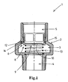
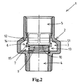
- Embodiments of the assembly, the kit of parts, and the use thereof will be described by way of example only, with reference to the accompanying schematic drawings in which corresponding reference symbols indicate corresponding parts, and in which:
- the
Figures 1-3 schematically show a view in cross section of an embodiment of a connector according the invention, - the
Figures 4 and5 schematically show a view in cross section of an embodiment of an assembly comprising the connector offig. 1-3 and a safety valve device, -
Figure 6 schematically shows a view in cross section of an embodiment of a kit of parts comprising the connector offig. 1-3 and the safety valve device offig. 4-5 , and -
Figure 7 schematically shows a view in cross section of the connector offig. 1-3 . - The
figures 1-3 show a view in cross section of an embodiment of aconnector 1 according the invention. Theconnector 1 is constructed to connect asafety valve device 31 to a fluid system. Theconnector 1 comprises aconnector body 2 defining aconnector channel 3 having aconnector inlet 4 and aconnector outlet 5. Theconnector valve 6 is provided in theconnector channel 3. Theconnector valve 6 is movable into anopen position 7 and into aclosed position 8. In theopen position 7 theconnector valve 6 does not close theconnector channel 3. In theclosed position 8 theconnector valve 6 closes theconnector channel 3. Theconnector valve 6 comprises afluid passage 9 which is sealed by a sealingmember 10. The sealingmember 10 is constructed and arranged to loose its sealing function when a fluid pressure at theconnector inlet 4 exceeds a predetermined value so that theconnector inlet 4 andconnector outlet 5 are in fluid connection via thefluid passage 9 while theconnector valve 6 is located in theclosed position 8. - In
fig. 1 , theconnector valve 6 is located in theclosed position 8. Thefluid passage 9 is sealed by the sealingmember 10. This way, thefluid passage 9 is closed so that no fluid can flow trough thefluid passage 9. The sealingmember 10 is connected to theconnector valve 6. Acontact surface 12 is provided in theconnector channel 3. Thecontact surface 12 is provided on theinside connector wall 14 of theconnector 1. In theclosed position 8 theconnector valve 6 is in contact with thecontact surface 12 in a sealing manner. More specifically, theconnector valve 6 comprises aconnector valve member 15 and in theclosed position 8; theconnector valve member 15 is in contact with thecontact surface 12 in a sealing manner. This way, theconnector channel 3 is closed by theconnector valve 6 so that no fluid can pass theconnector valve 6. In said situation, theconnector inlet 4 and theconnector outlet 5 are not in fluid connection. - The
connector valve 6 comprises adrive member 13 to drive theconnector valve 6 in theclosed position 8. Thedrive member 13 continuously applies a force to theconnector valve 6 to drive theconnector valve 6 into theclosed position 8. Thedrive member 13 is a spring. In other examples, the drive member may be any other suitable driver constructed and arranged to drive theconnector valve 6 in theclosed position 8, such as a member made of resilient material. Theconnector valve member 15 extends through part of theconnector channel 3. When thesafety device 31 is connected to theconnector outlet 5, theconnector valve member 15 is pushed by thesafety device 31 so thatconnector valve 6 is moved into theopen position 7. - In
fig. 2 , theconnector valve 6 is located in theopen position 7. Thefluid passage 9 is sealed by the sealingmember 10. In theopen position 7 theconnector valve 6 is located at a distance from thecontact surface 12. More specifically, theconnector valve member 15 is located at a distance from thecontact surface 12. This way, afirst fluid opening 51 through which fluid can flow is created. This allows fluid to pass theconnector valve 6. In said situation, theconnector inlet 4 and theconnector outlet 5 are in fluid connection via thefirst fluid opening 51. - In
fig. 3 , theconnector valve 6 is located in theclosed position 8. Theconnector valve 6 is moved into theclosed position 8 when in use thesafety valve device 31 is disconnected from theconnector 1. The sealingmember 10 has lost its sealing function because a fluid pressure at theconnector inlet 4 exceeded the predetermined value. Asecond fluid opening 52 through which fluid can flow is created. The sealingmember 10 has lost its connection with theconnector valve 6, so that the sealingmember 10 is disconnected from theconnector valve 6. In a different embodiment, the sealingmember 10 remains connected to theconnector valve 6 but breaks when the fluid pressure in theconnector inlet 4 exceeds the predetermined value. Because the sealingmember 10 is not sealing thefluid passage 9 anymore, fluid can flow through the fluid passage 9 (forming the second fluid opening 52) and pass theconnector valve 6 located in theclosed position 8. This way, theconnector inlet 4 and theconnector outlet 5 are in fluid connection via thesecond fluid opening 52 while theconnector valve 6 is located in theclosed position 8. - The
fig. 4-7 indicate the use of theconnector 1 when connected to a fluid system (not shown). Theconnector 1 is connected to the fluid system via theconnector inlet 4. The flow direction of the fluid is infig. 4-7 indicated by arrows. - In
fig. 4 , asafety valve device 31 is connected to the fluid system via theconnector 1. Thesafety valve device 31 comprises avalve body 32 defining avalve channel 33 having avalve inlet 34 and avalve outlet 35. Thevalve inlet 34 is connected to theconnector outlet 5 of theconnector 1 such that theconnector valve 6 is moved into theopen position 7. Asafety valve 36 is provided in thevalve channel 33. Thesafety valve 36 is constructed and arranged to close thevalve channel 33 when a fluid pressure at thevalve inlet 34 is lower than or equal to the predetermined value and to open thevalve channel 33 when the fluid pressure at thevalve inlet 34 exceeds the predetermined value. - The
connector valve 6 is moved in theopen position 7 by thevalve inlet 34 of thesafety valve device 31 which is connected toconnection outlet 5 of theconnector 1. Fluid can flow through thefirst fluid opening 51 and pass theconnector valve 6. The fluid can flow from theconnector inlet 4 into theconnector outlet 5 and thevalve inlet 34. Theconnector inlet 4, theconnector outlet 5 and thevalve inlet 34 are in fluid connection. The flow capacity through theconnector inlet 4 equals the flow capacity through thevalve inlet 34. The size of theconnector inlet 4 is equal to the size of thevalve inlet 34. - In the situation shown, the fluid pressure in the fluid system is below the predetermined value. Therefore, the fluid pressure in the
valve inlet 34 is smaller than the predetermined value. Thevalve channel 33 of thesafety valve device 31 is closed by thesafety valve 36. This means that the fluid is blocked by thesafety valve 36. The fluid can not flow from thevalve inlet 34 into thevalve outlet 35. -
Fig. 5 shows the same situation as infig. 4 , but with the difference that the fluid pressure in the fluid system is increased and exceeds the predetermined value. This means that the fluid pressure in thevalve inlet 34 also exceeds the predetermined value. Thevalve channel 33 of thesafety valve device 31 is opened by thesafety valve 36. This way, athird fluid opening 53 is created. This means that the fluid is not blocked by thesafety valve 36. The fluid can flow from thevalve inlet 34 into thevalve outlet 35 via thethird fluid opening 53. Theconnector inlet 4, theconnector outlet 5, thevalve inlet 34 and thevalve outlet 35 are in fluid connection. The fluid can flow out of thevalve outlet 35 and leave the fluid system. As a result of this, the pressure in the fluid system (and therefore also in the valve inlet 34) will drop. When the pressure drops to a value below or equal to the predetermined value, thesafety valve 36 will close thevalve channel 33 again so that no fluid can flow out of thevalve outlet 35 and leave the fluid system. This way, the assembly of theconnector 1 andsafety valve device 31 ensures that the pressure in the fluid system does not exceed the predetermined value. - In
fig. 6 , thesafety valve device 31 is disconnected from theconnector 1. In practice, there are many reasons why thesafety valve device 31 will be disconnected from the fluid system. This may for example be when thesafety valve device 31 is replaced during maintenance of the fluid system. - When the
safety valve device 31 is disconnected from theconnector 1, theconnector valve 6 is moved into the closed position by thedrive member 13. - In the
closed position 8, theconnector valve 6 blocks the fluid so that the fluid can not flow from theconnector inlet 4 into theconnector outlet 5. This way, the fluid can not leave the fluid system. This makes it possible that thesafety valve device 31 can be disconnected from the fluid system without the need that the fluid first has to be removed from the fluid system. - If in the situation shown in
fig. 7 , the fluid pressure in the fluid system (and therefore also at the connecter inlet 4) exceed the predetermined value, the sealingmember 10 will loose its sealing function so that theconnector inlet 4 andconnector outlet 5 are in fluid connection via the fluid passage 9 (forming the second fluid passage 52) while theconnector valve 6 is located in theclosed position 8. This way, the fluid is able to flow from theconnector inlet 4 into theconnector outlet 5 and leave the fluid system via theconnector outlet 5 so that the pressure in the fluid system will drop. This situation is shown infig. 7 . Theconnector 1 ensures that the pressure in the fluid system does not exceed the predetermined value in the situation that thesafety valve device 31 is disconnected from the fluid system, more specifically that thesafety valve device 31 is disconnected from theconnector 1. Theconnector 1 and thesafety valve device 31 discharge the fluid at the same predetermined pressure. This allows that thesafety valve device 31 can be removed without first (partly) removing the fluid from the fluid system and without the risk that the pressure in the fluid system will exeed the predetermined pressure when the safety valve device is disconnected from the fluid system. This way, it is for example possible to preplaced the safety valve device in time efficient and save manner. - The flow capacity through the
connector channel 3 of theconnector 1 in the situation that theconnector valve 6 is located in theclosed position 8 and the sealingmember 10 has lost its sealing function is equal to or larger than the flow capacity through thevalve channel 33 of thesafety valve device 31 in the situation that thesafety valve 36 opens thevalve channel 33. This ensures that the amount of water which can flow per second through saidconnector channel 3 is equal to or larger than the amount of water which can flow per second through saidvalve channel 33. - The flow capacity through the
connector channel 3 of theconnector 1 in the situation that theconnector valve 6 is located in theopen position 8 and the sealingmember 10 has its sealing function is equal to or larger than the flow capacity through thevalve channel 33 of thesafety valve device 31 in the situation that thesafety valve 36 opens thevalve channel 33. - Each of the
first fluid opening 51 and thesecond fluid opening 52 is equal to or larger than thethird fluid opening 53. - It will be apparent to those skilled in the art that various modifications can be made to the connector, the assembly, the kit of parts and the use without departing from the scope as defined by the claims.
Claims (15)
- Assembly comprising
a connector (1) for connecting a safety valve device (31) to a fluid system, wherein:- the connector comprises a connector body (2) defining a connector channel (3) having a connector inlet (4) and a connector outlet (5),- a connector valve (6) is provided in the connector channel (3), which connector valve (6) is movable into an open position and into a closed position,- in the open position the connector valve (6) does not connector connector channel (3) and in the closed position the connector valve (6) closes the connector channel (3), and- the connector valve (6) comprises a fluid passage (9) which is sealed by a sealing member (10), which sealing member (10) looses its sealing function when a fluid pressure at the connector inlet (4) exceeds a predetermined value so that the connector inlet (4) and connector outlet (5) are in fluid connection while the connector valve (6) is located in the closed position, and further comprising
a safety valve device (31), wherein;- the safety valve device (31) comprises a valve body (32) defining a valve channel (33) having a valve inlet (34) and a valve outlet (35),- the valve inlet (34) is connected to the connector outlet (5) of the connector such that the connector valve (6) is moved into the open position, and- a safety valve (36) is provided in the valve channel (33), which safety valve (36) closes the valve channel when a fluid pressure at the valve inlet (34) is lower than or equal to the predetermined value and opens the valve channel (33) when the fluid pressure at the valve inlet (34) exceeds the predetermined value. - Assembly according to claim 1, wherein the flow capacity through the connector channel (3) of the connector in the situation that the connector valve (6) is located in the closed position and the sealing member (10) has lost its sealing function is equal to or larger than the flow capacity through the valve channel (33) of the safety valve device (31) in the situation that the safety valve opens the valve channel (33).
- Assembly according to claim 1 or 2, wherein the flow capacity through the connector channel (3) of the connector (1) in the situation that the connector valve (6) is located in the open position and the sealing member (10) has its sealing function equal to or larger than the flow capacity through the valve channel (33) of the safety valve device (31) in the situation that the safety valve (36) opens the valve channel (33).
- Assembly according to any of the preceding claims, wherein- the connector channel (3) and the connector valve (6) located in the open position define a first fluid opening through which fluid can flow,- the fluid passage not sealed by the sealing member (10) defines a second fluid opening through which fluid can flow,- the valve channel (3) and the opened safety valve (36) define a third fluid opening through which fluid can flow, and- at a fluid pressure exceeding the predetermined value each of the first fluid opening and the second fluid opening is equal to or larger than the third fluid opening.
- Assembly according to any of the preceding claims, wherein the flow capacity through the connector inlet (4) of the connector (1) equals the flow capacity through the valve inlet (34) of the safety valve device (31).
- Assembly according to any of the preceding claims, wherein the size of the connector inlet (4) of the connector (1) is equal to the size of the valve inlet (34) of the safety valve device (31).
- Assembly according to any of the preceding claims, wherein the connector valve (6) is moved into the open position when in use the safety valve (36) device is connected to the connector outlet (5) and is moved into the closed position when in use the safety valve device (31) is disconnected from the connector outlet (5).
- Assembly according to any of the preceding claims, wherein the sealing member (10) is connected to the connector valve (6) and the sealing member (10) looses its connection to the connector valve (6) when the fluid pressure at the connector inlet (4) exceeds the predetermined value.
- Assembly according to any of the preceding claims, wherein the sealing member (10) is connected to the connector valve (6) and the sealing member (10) breaks when the fluid pressure at the connector inlet (4) exceeds the predetermined value.
- Assembly according to any of the preceding claims, wherein a contact surface (12) is provided in the connector channel (3) and in the closed position the connector valve (6) is in contact with the contact surface (12) in a sealing manner.
- Assembly according to claim 10, wherein in the open position the connector valve (6) is located at a distance from the contact surface (12).
- Assembly according to any of the preceding claims, wherein the connector valve (6) comprises a drive member (13) to drive the connector valve (6) in the closed position.
- Kit of parts comprising
a connector (1) for connecting a safety valve device (31) to a fluid system, wherein;- the connector (1) comprises a connector body (2) defining a connector channel (3) having a connector inlet (4) and a connector outlet (5),- a connector valve (6) is provided in the connector channel (3), which connector valve (6) is movable into an open position and into a closed position,- in the open position the connector valve (6) does not close the connector channel (3) and in the closed position the connector valve (6) closes the connector channel (3), and- the connector valve (6) comprises a fluid passage which is sealed by a sealing member (10), which sealing member (10) looses its sealing function when a fluid pressure at the connector inlet (4) exceeds a predetermined value so that the connector inlet (4) and connector outlet (5) are in fluid connection while the connector valve (6) is located in the closed position, and further comprising
a safety valve device (31), wherein;- the safety valve device (31) comprises a valve body (32) defining a valve channel (33) having a valve inlet (34) and a valve outlet (35),- the valve inlet (34) is connectable to the connector outlet (5) of the connector (1) such that the connector valve is moved into the open position, and- a safety valve (36) is provided in the valve channel (33), which safety valve (36) closes the valve channel (33) when a fluid pressure at the valve inlet is lower than or equal to the predetermined value and opens the valve channel (33) when the fluid pressure at the valve inlet (34) exceeds the predetermined value. - Fluid system comprising an assembly according to any of the claims 1-12, wherein the safety valve device (31) is connected to the fluid system via the connector (1).
- Fluid system according to claim 14, wherein the fluid system is a heating system or a cooling system.
Applications Claiming Priority (2)
| Application Number | Priority Date | Filing Date | Title |
|---|---|---|---|
| NL2008802 | 2012-05-11 | ||
| PCT/NL2013/050347 WO2013169107A1 (en) | 2012-05-11 | 2013-05-08 | Assembly comprising a connector and a safety valve device |
Publications (2)
| Publication Number | Publication Date |
|---|---|
| EP2847503A1 EP2847503A1 (en) | 2015-03-18 |
| EP2847503B1 true EP2847503B1 (en) | 2016-01-20 |
Family
ID=48468732
Family Applications (1)
| Application Number | Title | Priority Date | Filing Date |
|---|---|---|---|
| EP13724014.9A Not-in-force EP2847503B1 (en) | 2012-05-11 | 2013-05-08 | Assembly comprising a connector and a safety valve device |
Country Status (2)
| Country | Link |
|---|---|
| EP (1) | EP2847503B1 (en) |
| WO (1) | WO2013169107A1 (en) |
Family Cites Families (3)
| Publication number | Priority date | Publication date | Assignee | Title |
|---|---|---|---|---|
| FR523876A (en) * | 1921-01-26 | 1921-08-26 | Auguste Olivier | Improvements made to taps in general |
| GB466311A (en) * | 1936-06-05 | 1937-05-26 | Hugh Thomas Shaw Mcclintock | Improvements in and relating to automatic sealing valves for water taps and the like |
| DE2335196B2 (en) * | 1973-07-11 | 1975-07-17 | Schulz-Pruss Geb. Kaufmann, Gisela, 3004 Isernhagen | Valve |
-
2013
- 2013-05-08 WO PCT/NL2013/050347 patent/WO2013169107A1/en not_active Ceased
- 2013-05-08 EP EP13724014.9A patent/EP2847503B1/en not_active Not-in-force
Also Published As
| Publication number | Publication date |
|---|---|
| EP2847503A1 (en) | 2015-03-18 |
| WO2013169107A1 (en) | 2013-11-14 |
Similar Documents
| Publication | Publication Date | Title |
|---|---|---|
| EP3190323B1 (en) | Flow control valve | |
| US11358089B2 (en) | Snap in place natural gas filter | |
| CN204677834U (en) | Reduction valve | |
| WO2011013142A3 (en) | End of life system for a water filter | |
| EP2325407B1 (en) | Bypass valve | |
| ITMI20111315A1 (en) | FILTERING EQUIPMENT | |
| CN102711958B (en) | Combination relief valve and drainage mechanism requiring inserted element to permit drainage in a coalescer system | |
| EP4421364A1 (en) | Automatic liquid drain device | |
| US20130270256A1 (en) | Instantaneous water heater | |
| EP3197582B1 (en) | Device for ventilation and integrity testing | |
| DE102012102861B4 (en) | CONTROL VALVE AND LIQUID RESERVOIR; THIS INCLUDES THIS | |
| EP2607811B1 (en) | Hot water tank with pressure relief device | |
| KR102024226B1 (en) | Pilot operated safety valve system | |
| EP2933546A1 (en) | Condensate drain device | |
| EP2366410B1 (en) | Valve for fluid inlet and outlet | |
| WO2013169107A1 (en) | Assembly comprising a connector and a safety valve device | |
| EP2971898B1 (en) | Fluid valve | |
| WO2013039743A1 (en) | Drain valve and method for operating a drain valve | |
| EP2830733B1 (en) | Filter housing for replaceable filters | |
| KR101964770B1 (en) | Water filter for preventing remaining water drop | |
| EP3159623A1 (en) | Water heater | |
| KR20090129828A (en) | Water heaters, including expansion tanks with on / off valves to prevent release, and expansion tanks for water heaters used therein | |
| DE102008060973A1 (en) | Ventilation valve for solar thermal systems and associated method | |
| CN207864678U (en) | A kind of ball valve facilitating installation strainer | |
| CN206503945U (en) | Be open adjustable gas valve |
Legal Events
| Date | Code | Title | Description |
|---|---|---|---|
| PUAI | Public reference made under article 153(3) epc to a published international application that has entered the european phase |
Free format text: ORIGINAL CODE: 0009012 |
|
| 17P | Request for examination filed |
Effective date: 20141211 |
|
| AK | Designated contracting states |
Kind code of ref document: A1 Designated state(s): AL AT BE BG CH CY CZ DE DK EE ES FI FR GB GR HR HU IE IS IT LI LT LU LV MC MK MT NL NO PL PT RO RS SE SI SK SM TR |
|
| AX | Request for extension of the european patent |
Extension state: BA ME |
|
| DAX | Request for extension of the european patent (deleted) | ||
| GRAP | Despatch of communication of intention to grant a patent |
Free format text: ORIGINAL CODE: EPIDOSNIGR1 |
|
| INTG | Intention to grant announced |
Effective date: 20150917 |
|
| GRAS | Grant fee paid |
Free format text: ORIGINAL CODE: EPIDOSNIGR3 |
|
| GRAA | (expected) grant |
Free format text: ORIGINAL CODE: 0009210 |
|
| AK | Designated contracting states |
Kind code of ref document: B1 Designated state(s): AL AT BE BG CH CY CZ DE DK EE ES FI FR GB GR HR HU IE IS IT LI LT LU LV MC MK MT NL NO PL PT RO RS SE SI SK SM TR |
|
| REG | Reference to a national code |
Ref country code: GB Ref legal event code: FG4D |
|
| REG | Reference to a national code |
Ref country code: CH Ref legal event code: EP |
|
| REG | Reference to a national code |
Ref country code: IE Ref legal event code: FG4D |
|
| REG | Reference to a national code |
Ref country code: AT Ref legal event code: REF Ref document number: 771893 Country of ref document: AT Kind code of ref document: T Effective date: 20160215 |
|
| REG | Reference to a national code |
Ref country code: DE Ref legal event code: R096 Ref document number: 602013004776 Country of ref document: DE |
|
| REG | Reference to a national code |
Ref country code: NL Ref legal event code: FP |
|
| REG | Reference to a national code |
Ref country code: LT Ref legal event code: MG4D |
|
| REG | Reference to a national code |
Ref country code: AT Ref legal event code: MK05 Ref document number: 771893 Country of ref document: AT Kind code of ref document: T Effective date: 20160120 |
|
| PG25 | Lapsed in a contracting state [announced via postgrant information from national office to epo] |
Ref country code: IT Free format text: LAPSE BECAUSE OF FAILURE TO SUBMIT A TRANSLATION OF THE DESCRIPTION OR TO PAY THE FEE WITHIN THE PRESCRIBED TIME-LIMIT Effective date: 20160120 Ref country code: FI Free format text: LAPSE BECAUSE OF FAILURE TO SUBMIT A TRANSLATION OF THE DESCRIPTION OR TO PAY THE FEE WITHIN THE PRESCRIBED TIME-LIMIT Effective date: 20160120 Ref country code: NO Free format text: LAPSE BECAUSE OF FAILURE TO SUBMIT A TRANSLATION OF THE DESCRIPTION OR TO PAY THE FEE WITHIN THE PRESCRIBED TIME-LIMIT Effective date: 20160420 Ref country code: ES Free format text: LAPSE BECAUSE OF FAILURE TO SUBMIT A TRANSLATION OF THE DESCRIPTION OR TO PAY THE FEE WITHIN THE PRESCRIBED TIME-LIMIT Effective date: 20160120 Ref country code: GR Free format text: LAPSE BECAUSE OF FAILURE TO SUBMIT A TRANSLATION OF THE DESCRIPTION OR TO PAY THE FEE WITHIN THE PRESCRIBED TIME-LIMIT Effective date: 20160421 Ref country code: HR Free format text: LAPSE BECAUSE OF FAILURE TO SUBMIT A TRANSLATION OF THE DESCRIPTION OR TO PAY THE FEE WITHIN THE PRESCRIBED TIME-LIMIT Effective date: 20160120 |
|
| REG | Reference to a national code |
Ref country code: FR Ref legal event code: PLFP Year of fee payment: 4 |
|
| PG25 | Lapsed in a contracting state [announced via postgrant information from national office to epo] |
Ref country code: LT Free format text: LAPSE BECAUSE OF FAILURE TO SUBMIT A TRANSLATION OF THE DESCRIPTION OR TO PAY THE FEE WITHIN THE PRESCRIBED TIME-LIMIT Effective date: 20160120 Ref country code: PT Free format text: LAPSE BECAUSE OF FAILURE TO SUBMIT A TRANSLATION OF THE DESCRIPTION OR TO PAY THE FEE WITHIN THE PRESCRIBED TIME-LIMIT Effective date: 20160520 Ref country code: SE Free format text: LAPSE BECAUSE OF FAILURE TO SUBMIT A TRANSLATION OF THE DESCRIPTION OR TO PAY THE FEE WITHIN THE PRESCRIBED TIME-LIMIT Effective date: 20160120 Ref country code: PL Free format text: LAPSE BECAUSE OF FAILURE TO SUBMIT A TRANSLATION OF THE DESCRIPTION OR TO PAY THE FEE WITHIN THE PRESCRIBED TIME-LIMIT Effective date: 20160120 Ref country code: RS Free format text: LAPSE BECAUSE OF FAILURE TO SUBMIT A TRANSLATION OF THE DESCRIPTION OR TO PAY THE FEE WITHIN THE PRESCRIBED TIME-LIMIT Effective date: 20160120 Ref country code: AT Free format text: LAPSE BECAUSE OF FAILURE TO SUBMIT A TRANSLATION OF THE DESCRIPTION OR TO PAY THE FEE WITHIN THE PRESCRIBED TIME-LIMIT Effective date: 20160120 Ref country code: IS Free format text: LAPSE BECAUSE OF FAILURE TO SUBMIT A TRANSLATION OF THE DESCRIPTION OR TO PAY THE FEE WITHIN THE PRESCRIBED TIME-LIMIT Effective date: 20160520 Ref country code: LV Free format text: LAPSE BECAUSE OF FAILURE TO SUBMIT A TRANSLATION OF THE DESCRIPTION OR TO PAY THE FEE WITHIN THE PRESCRIBED TIME-LIMIT Effective date: 20160120 |
|
| REG | Reference to a national code |
Ref country code: DE Ref legal event code: R097 Ref document number: 602013004776 Country of ref document: DE |
|
| PG25 | Lapsed in a contracting state [announced via postgrant information from national office to epo] |
Ref country code: EE Free format text: LAPSE BECAUSE OF FAILURE TO SUBMIT A TRANSLATION OF THE DESCRIPTION OR TO PAY THE FEE WITHIN THE PRESCRIBED TIME-LIMIT Effective date: 20160120 Ref country code: DK Free format text: LAPSE BECAUSE OF FAILURE TO SUBMIT A TRANSLATION OF THE DESCRIPTION OR TO PAY THE FEE WITHIN THE PRESCRIBED TIME-LIMIT Effective date: 20160120 |
|
| PLBE | No opposition filed within time limit |
Free format text: ORIGINAL CODE: 0009261 |
|
| STAA | Information on the status of an ep patent application or granted ep patent |
Free format text: STATUS: NO OPPOSITION FILED WITHIN TIME LIMIT |
|
| PG25 | Lapsed in a contracting state [announced via postgrant information from national office to epo] |
Ref country code: CZ Free format text: LAPSE BECAUSE OF FAILURE TO SUBMIT A TRANSLATION OF THE DESCRIPTION OR TO PAY THE FEE WITHIN THE PRESCRIBED TIME-LIMIT Effective date: 20160120 Ref country code: SM Free format text: LAPSE BECAUSE OF FAILURE TO SUBMIT A TRANSLATION OF THE DESCRIPTION OR TO PAY THE FEE WITHIN THE PRESCRIBED TIME-LIMIT Effective date: 20160120 Ref country code: RO Free format text: LAPSE BECAUSE OF FAILURE TO SUBMIT A TRANSLATION OF THE DESCRIPTION OR TO PAY THE FEE WITHIN THE PRESCRIBED TIME-LIMIT Effective date: 20160120 Ref country code: SK Free format text: LAPSE BECAUSE OF FAILURE TO SUBMIT A TRANSLATION OF THE DESCRIPTION OR TO PAY THE FEE WITHIN THE PRESCRIBED TIME-LIMIT Effective date: 20160120 |
|
| 26N | No opposition filed |
Effective date: 20161021 |
|
| PG25 | Lapsed in a contracting state [announced via postgrant information from national office to epo] |
Ref country code: LU Free format text: LAPSE BECAUSE OF FAILURE TO SUBMIT A TRANSLATION OF THE DESCRIPTION OR TO PAY THE FEE WITHIN THE PRESCRIBED TIME-LIMIT Effective date: 20160508 |
|
| REG | Reference to a national code |
Ref country code: CH Ref legal event code: PL |
|
| PG25 | Lapsed in a contracting state [announced via postgrant information from national office to epo] |
Ref country code: LI Free format text: LAPSE BECAUSE OF NON-PAYMENT OF DUE FEES Effective date: 20160531 Ref country code: CH Free format text: LAPSE BECAUSE OF NON-PAYMENT OF DUE FEES Effective date: 20160531 |
|
| REG | Reference to a national code |
Ref country code: IE Ref legal event code: MM4A |
|
| PG25 | Lapsed in a contracting state [announced via postgrant information from national office to epo] |
Ref country code: SI Free format text: LAPSE BECAUSE OF FAILURE TO SUBMIT A TRANSLATION OF THE DESCRIPTION OR TO PAY THE FEE WITHIN THE PRESCRIBED TIME-LIMIT Effective date: 20160120 Ref country code: BG Free format text: LAPSE BECAUSE OF FAILURE TO SUBMIT A TRANSLATION OF THE DESCRIPTION OR TO PAY THE FEE WITHIN THE PRESCRIBED TIME-LIMIT Effective date: 20160420 |
|
| REG | Reference to a national code |
Ref country code: FR Ref legal event code: PLFP Year of fee payment: 5 |
|
| PG25 | Lapsed in a contracting state [announced via postgrant information from national office to epo] |
Ref country code: IE Free format text: LAPSE BECAUSE OF NON-PAYMENT OF DUE FEES Effective date: 20160508 |
|
| PGFP | Annual fee paid to national office [announced via postgrant information from national office to epo] |
Ref country code: NL Payment date: 20170530 Year of fee payment: 5 |
|
| PGFP | Annual fee paid to national office [announced via postgrant information from national office to epo] |
Ref country code: DE Payment date: 20170525 Year of fee payment: 5 Ref country code: GB Payment date: 20170425 Year of fee payment: 5 Ref country code: FR Payment date: 20170529 Year of fee payment: 5 |
|
| PGFP | Annual fee paid to national office [announced via postgrant information from national office to epo] |
Ref country code: BE Payment date: 20170529 Year of fee payment: 5 |
|
| PG25 | Lapsed in a contracting state [announced via postgrant information from national office to epo] |
Ref country code: HU Free format text: LAPSE BECAUSE OF FAILURE TO SUBMIT A TRANSLATION OF THE DESCRIPTION OR TO PAY THE FEE WITHIN THE PRESCRIBED TIME-LIMIT; INVALID AB INITIO Effective date: 20130508 |
|
| PG25 | Lapsed in a contracting state [announced via postgrant information from national office to epo] |
Ref country code: MC Free format text: LAPSE BECAUSE OF FAILURE TO SUBMIT A TRANSLATION OF THE DESCRIPTION OR TO PAY THE FEE WITHIN THE PRESCRIBED TIME-LIMIT Effective date: 20160120 Ref country code: CY Free format text: LAPSE BECAUSE OF FAILURE TO SUBMIT A TRANSLATION OF THE DESCRIPTION OR TO PAY THE FEE WITHIN THE PRESCRIBED TIME-LIMIT Effective date: 20160120 Ref country code: MK Free format text: LAPSE BECAUSE OF FAILURE TO SUBMIT A TRANSLATION OF THE DESCRIPTION OR TO PAY THE FEE WITHIN THE PRESCRIBED TIME-LIMIT Effective date: 20160120 Ref country code: MT Free format text: LAPSE BECAUSE OF NON-PAYMENT OF DUE FEES Effective date: 20160531 |
|
| PG25 | Lapsed in a contracting state [announced via postgrant information from national office to epo] |
Ref country code: AL Free format text: LAPSE BECAUSE OF FAILURE TO SUBMIT A TRANSLATION OF THE DESCRIPTION OR TO PAY THE FEE WITHIN THE PRESCRIBED TIME-LIMIT Effective date: 20160120 Ref country code: TR Free format text: LAPSE BECAUSE OF FAILURE TO SUBMIT A TRANSLATION OF THE DESCRIPTION OR TO PAY THE FEE WITHIN THE PRESCRIBED TIME-LIMIT Effective date: 20160120 |
|
| REG | Reference to a national code |
Ref country code: DE Ref legal event code: R119 Ref document number: 602013004776 Country of ref document: DE |
|
| REG | Reference to a national code |
Ref country code: NL Ref legal event code: MM Effective date: 20180601 |
|
| GBPC | Gb: european patent ceased through non-payment of renewal fee |
Effective date: 20180508 |
|
| REG | Reference to a national code |
Ref country code: BE Ref legal event code: FP Effective date: 20160413 Ref country code: BE Ref legal event code: MM Effective date: 20180531 |
|
| PG25 | Lapsed in a contracting state [announced via postgrant information from national office to epo] |
Ref country code: NL Free format text: LAPSE BECAUSE OF NON-PAYMENT OF DUE FEES Effective date: 20180601 Ref country code: GB Free format text: LAPSE BECAUSE OF NON-PAYMENT OF DUE FEES Effective date: 20180508 Ref country code: DE Free format text: LAPSE BECAUSE OF NON-PAYMENT OF DUE FEES Effective date: 20181201 Ref country code: FR Free format text: LAPSE BECAUSE OF NON-PAYMENT OF DUE FEES Effective date: 20180531 |
|
| PG25 | Lapsed in a contracting state [announced via postgrant information from national office to epo] |
Ref country code: BE Free format text: LAPSE BECAUSE OF NON-PAYMENT OF DUE FEES Effective date: 20180531 |