EP2847470B1 - Retainer for fixing a control device to a container - Google Patents
Retainer for fixing a control device to a container Download PDFInfo
- Publication number
- EP2847470B1 EP2847470B1 EP13788602.4A EP13788602A EP2847470B1 EP 2847470 B1 EP2847470 B1 EP 2847470B1 EP 13788602 A EP13788602 A EP 13788602A EP 2847470 B1 EP2847470 B1 EP 2847470B1
- Authority
- EP
- European Patent Office
- Prior art keywords
- retainer
- control device
- wire
- intended
- limbs
- Prior art date
- Legal status (The legal status is an assumption and is not a legal conclusion. Google has not performed a legal analysis and makes no representation as to the accuracy of the status listed.)
- Active
Links
Images


Classifications
-
- F—MECHANICAL ENGINEERING; LIGHTING; HEATING; WEAPONS; BLASTING
- F16—ENGINEERING ELEMENTS AND UNITS; GENERAL MEASURES FOR PRODUCING AND MAINTAINING EFFECTIVE FUNCTIONING OF MACHINES OR INSTALLATIONS; THERMAL INSULATION IN GENERAL
- F16B—DEVICES FOR FASTENING OR SECURING CONSTRUCTIONAL ELEMENTS OR MACHINE PARTS TOGETHER, e.g. NAILS, BOLTS, CIRCLIPS, CLAMPS, CLIPS OR WEDGES; JOINTS OR JOINTING
- F16B2/00—Friction-grip releasable fastenings
- F16B2/20—Clips, i.e. with gripping action effected solely by the inherent resistance to deformation of the material of the fastening
- F16B2/22—Clips, i.e. with gripping action effected solely by the inherent resistance to deformation of the material of the fastening of resilient material, e.g. rubbery material
-
- B—PERFORMING OPERATIONS; TRANSPORTING
- B65—CONVEYING; PACKING; STORING; HANDLING THIN OR FILAMENTARY MATERIAL
- B65D—CONTAINERS FOR STORAGE OR TRANSPORT OF ARTICLES OR MATERIALS, e.g. BAGS, BARRELS, BOTTLES, BOXES, CANS, CARTONS, CRATES, DRUMS, JARS, TANKS, HOPPERS, FORWARDING CONTAINERS; ACCESSORIES, CLOSURES, OR FITTINGS THEREFOR; PACKAGING ELEMENTS; PACKAGES
- B65D25/00—Details of other kinds or types of rigid or semi-rigid containers
- B65D25/38—Devices for discharging contents
-
- F—MECHANICAL ENGINEERING; LIGHTING; HEATING; WEAPONS; BLASTING
- F16—ENGINEERING ELEMENTS AND UNITS; GENERAL MEASURES FOR PRODUCING AND MAINTAINING EFFECTIVE FUNCTIONING OF MACHINES OR INSTALLATIONS; THERMAL INSULATION IN GENERAL
- F16B—DEVICES FOR FASTENING OR SECURING CONSTRUCTIONAL ELEMENTS OR MACHINE PARTS TOGETHER, e.g. NAILS, BOLTS, CIRCLIPS, CLAMPS, CLIPS OR WEDGES; JOINTS OR JOINTING
- F16B5/00—Joining sheets or plates, e.g. panels, to one another or to strips or bars parallel to them
- F16B5/06—Joining sheets or plates, e.g. panels, to one another or to strips or bars parallel to them by means of clamps or clips
-
- F—MECHANICAL ENGINEERING; LIGHTING; HEATING; WEAPONS; BLASTING
- F16—ENGINEERING ELEMENTS AND UNITS; GENERAL MEASURES FOR PRODUCING AND MAINTAINING EFFECTIVE FUNCTIONING OF MACHINES OR INSTALLATIONS; THERMAL INSULATION IN GENERAL
- F16M—FRAMES, CASINGS OR BEDS OF ENGINES, MACHINES OR APPARATUS, NOT SPECIFIC TO ENGINES, MACHINES OR APPARATUS PROVIDED FOR ELSEWHERE; STANDS; SUPPORTS
- F16M13/00—Other supports for positioning apparatus or articles; Means for steadying hand-held apparatus or articles
- F16M13/02—Other supports for positioning apparatus or articles; Means for steadying hand-held apparatus or articles for supporting on, or attaching to, an object, e.g. tree, gate, window-frame, cycle
-
- F—MECHANICAL ENGINEERING; LIGHTING; HEATING; WEAPONS; BLASTING
- F17—STORING OR DISTRIBUTING GASES OR LIQUIDS
- F17C—VESSELS FOR CONTAINING OR STORING COMPRESSED, LIQUEFIED OR SOLIDIFIED GASES; FIXED-CAPACITY GAS-HOLDERS; FILLING VESSELS WITH, OR DISCHARGING FROM VESSELS, COMPRESSED, LIQUEFIED, OR SOLIDIFIED GASES
- F17C13/00—Details of vessels or of the filling or discharging of vessels
-
- F—MECHANICAL ENGINEERING; LIGHTING; HEATING; WEAPONS; BLASTING
- F16—ENGINEERING ELEMENTS AND UNITS; GENERAL MEASURES FOR PRODUCING AND MAINTAINING EFFECTIVE FUNCTIONING OF MACHINES OR INSTALLATIONS; THERMAL INSULATION IN GENERAL
- F16B—DEVICES FOR FASTENING OR SECURING CONSTRUCTIONAL ELEMENTS OR MACHINE PARTS TOGETHER, e.g. NAILS, BOLTS, CIRCLIPS, CLAMPS, CLIPS OR WEDGES; JOINTS OR JOINTING
- F16B2/00—Friction-grip releasable fastenings
- F16B2/02—Clamps, i.e. with gripping action effected by positive means other than the inherent resistance to deformation of the material of the fastening
- F16B2/06—Clamps, i.e. with gripping action effected by positive means other than the inherent resistance to deformation of the material of the fastening external, i.e. with contracting action
- F16B2/08—Clamps, i.e. with gripping action effected by positive means other than the inherent resistance to deformation of the material of the fastening external, i.e. with contracting action using bands
Definitions
- the present invention relates to a retainer for fixing a control device to a pressure tank or similar container.
- the invention is primarily intended for use on heavy commercial vehicles, e.g. trucks and buses, but may of course also be used on other types of vehicles, e.g. contractor machines, watercraft etc. equipped with operating means which are preferably associated with some form of container and have to be regulated by means of a wire or similar elongate object.
- the invention relates also to vehicles equipped with a retainer according to the invention.
- Heavy commercial vehicles are now normally equipped with one or more pressure tanks to store compressed air which is for example used for the vehicle's brake system.
- These pressure tanks have to be regularly drained of liquid which accumulates in them, e.g. in the form of condensate, using for the purpose at least one drain valve situated in the portion of the pressure tank which in its fitted state on the vehicle is directed downwards, towards the ground.
- the drain valve is usually opened by manual operation of a wire which has at its outer end a loop to make it easier for a user to handle and its inner other end fastened in the activating means of the drain valve.
- the pressure tank or tanks have to be fitted in such a way as to remain securely fastened in the vehicle's chassis at their intended locations even during temporarily difficult conditions, e.g. when the vehicle is travelling on a very uneven running surface or is involved in an accident.
- the drain valve has always to be easy to open and its operating wire needs to be easy to reach, and also to fit.
- Pressure tanks are currently fitted to vehicles by means, for example, of some form of strap or wire which has a loop at its outer end and is inserted, in conjunction with a rubber bushing, through a hollow in a bracket intended for the purpose. Thereafter the inner end of the wire has to be hooked or fitted firmly in the drain valve which, once the pressure tank has been put into its intended position in the vehicle, will be at a location which is masked and difficult to reach. After the wire has been fastened to the drain valve, the rubber bushing has to be pushed firmly into correct position in the wire retainer. As this operation is difficult and calls for precision, it is time-consuming and therefore expensive.
- One object of the invention is to solve the aforesaid problems and propose a retainer which is for example intended for an operating means/control device, e.g. a wire or some other elongate object, for a drain valve situated on a pressure tank, and which in a simple and cost-effective way makes it easy to fit said operating means/control device.
- an operating means/control device e.g. a wire or some other elongate object
- a further object of the invention is that it should be possible for the control device/the wire to be fitted to the pressure tank without having to be inserted through a closed loop or hollow which complicates the work.
- a further object of the invention is that it should be possible for the control device/the wire to be fitted in a single manufacturing operation and be at the same time easy to fasten in the activating means of the drain valve.
- a further object of the invention is that the control device/the wire should remain securely held in the retainer after the fitting operation has been completed but nevertheless be easy to move in axial directions so that the drain valve can easily be opened and closed throughout the vehicle's life cycle.
- a further object of the invention is that the structure of the retainer should be simple and comprise as few parts as possible.
- a further object of the invention is that constituent parts should be of low weight and easy and inexpensive to manufacture.
- the invention is primarily intended for heavy commercial vehicles, e.g. trucks, buses and the like, but may of course also be used in other types of vehicles equipped with some form of tank or container and provided with a device which has to be operated by means of a control device, e.g. a wire or some other elongate device, and needs, during operation of the vehicle, to remain held in a specific position relative to the tank.
- a control device e.g. a wire or some other elongate device
- An important object of the invention is to simplify the fitting of the retainer and the control device so that manufacture is speeded up and becomes more cost-effective.
- the invention is achieved by a retainer made of, for example, plastic such as EPDM or the like being provided with an open recess so that two limbs are formed, which recess is intended for the insertion sideways into the retainer of a control device in the form of an elongate object such as a wire or the like.
- the retainer is further provided with a channel for a preferably straplike element made of plastic or metal intended for fitting and clamping to an adjacent vehicle component, e.g. a pressure tank or the like.
- an adjacent vehicle component e.g. a pressure tank or the like.
- the solution according to the invention results in simplified handling and hence more cost-effective fitting. This also makes the solution easier and less expensive to implement not only during manufacture of new vehicles but also when adapting, maintaining or replacing the respective equipment on existing vehicles.
- Figure 1 depicts a side view of a conventional pressure tank 1 for compressed air fastened to a vehicle chassis via a bracket 2 by means of a strap 3 and provided for example with a wire 4 which is intended for regulation of the tank's drain valve 5 and is held in place by means of a retainer 6 according to the invention which is fitted to the tank 1 by means of a straplike element 7.
- Figure 2 depicts the same structure as in Figure 1 but showing the tank 1 as seen from below and without the bracket 2 so that the drain valve 5 and the positioning of the wire 4 are more clearly visible.
- the control device or the wire has its inner end fastened in the operating means of the drain valve so that the valve can be opened and closed, and the looped outer end of the wire is situated close to the tank's outer endwall which is usually fitted at the side of the vehicle to facilitate access to the control device/the wire.
- the wire runs through a retainer 6 according to the invention and is therefore readily accessible to the user when the draining operation is to be performed.
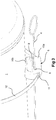
- Figure 3 depicts a partial view of the pressure tank 1 as seen obliquely from below, showing in more detail the fitted state of the retainer 6 and how the control device/the wire 4 is arranged and runs through the retainer.
- the retainer 6 preferably takes the form of a single integrated unit made with advantage of plastic, e.g. EPDM. It is provided with an opening or hollow 8 which is positioned substantially centrally and intended for a wire 4 or similar means. The hollow is open on one side of the retainer via a recess 9 in such a way that the retainer forms two limbs 10a,b which can spring relative to one another.
- the recess 9 is intended for insertion of an elongate control device such as a steel wire 4, a metal or plastic rod or similar means made of some other material rigid enough to operate, for example, a drain valve.
- the retainer is also provided with a channel 11 which runs through one of the retainer's limbs 10a and is intended for a plastic or metal straplike element 12.
- the straplike element makes it easy for the retainer to be fitted and clamped against or round an adjacent component of the vehicle, e.g. a pressure tank or the like.
- the retainer When the straplike element is duly tightened, the retainer is held firmly in its intended place relative to the vehicle part while at the same time its limbs 10a,b are pressed towards one another against the action of their inherent spring force.
- the retainer is thus prevented from sliding out of position and the control device/the wire 4 is prevented from sliding sideways out of the retainer but is nevertheless allowed to slide in the wire's axial direction, i.e. transversely through the retainer. Assurance that the drain valve 5 situated on the tank can easily be opened or closed is thus provided.
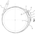
- Figure 4 depicts a plan view from one end of the pressure tank 1, showing the retainer 6, the wire 4, the drain valve 5 and parts of the tank's fastening or clamping devices 3. It shows the straplike element 12 extending round the tank and through the retainer's outer limb 10a. When the straplike element if tightened, the retainer's outer limb 10a is clamped to the central portion of the tank and thereby limits the space in the recess 9 so that the control device/the wire 4 cannot slide sideways out of the retainer.
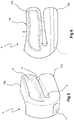
- Figure 5 depicts a perspective view obliquely from the side of a retainer 6 according to the invention.
- the central opening 8 and the recess 9 which is open outwards on one side form two limbs 10a,b whose end portions can be pressed towards one another and prevent for example a wire (not depicted) from sliding out through the recess 9.
- the channel 11 for a straplike element (not depicted) is situated in one limb 10a.
- the retainer may be provided with other apertures 13 to reduce the amount of material required for, and the weight of, the retainer during manufacture.
- Figure 6 depicts a side view of the retainer 6 according to the invention. It shows how one limb 10b which in the fitted state abuts against the pressure tank has a curvature 14 to better match the radius of the tank. This curvature may of course be configured in different ways appropriate to the component to which the retainer is intended to be fitted.
- the diagram also illustrates how the channel 11 for a straplike element extends through the inner limb 10a.
- Figures 7a -i depict various side views of a number of different embodiment variants of retainers according to the invention.
- the retainer's resilient limbs 10a,b have their outer end regions configured differently to make it easier during fitting for a control device or a wire to be inserted into the retainer by the limbs 10a,b being somewhat open in an unconstrained state or alternatively being able to spring apart slightly when the control device/the wire 4 is inserted into the recess but thereafter being held in the retainer's central hollow, particularly after the straplike element has been fitted and has firmly clamped the retainer to the pressure tank and has thereby pressed the limbs 10a,b towards one another.
- the outer end regions of the limbs 10a,b may be provided with some form of limiting means 14 to prevent or hinder the control device/the wire 4 from sliding out of the central hollow 8 or the recess 9 when it has been properly inserted into the recess.
- the limiting means 14 in the various diagrams in Figure 7 are in most cases self-explanatory.
- Figure 7c shows for example a circular cylindrical means pressed towards one another and performing a locking function.
- Figure 7i shows a triangular means pressed down towards a hemispherical component.
Landscapes
- Engineering & Computer Science (AREA)
- General Engineering & Computer Science (AREA)
- Mechanical Engineering (AREA)
- Clamps And Clips (AREA)
- Transmission Of Braking Force In Braking Systems (AREA)
- Valves And Accessory Devices For Braking Systems (AREA)
Description
- The present invention relates to a retainer for fixing a control device to a pressure tank or similar container. The invention is primarily intended for use on heavy commercial vehicles, e.g. trucks and buses, but may of course also be used on other types of vehicles, e.g. contractor machines, watercraft etc. equipped with operating means which are preferably associated with some form of container and have to be regulated by means of a wire or similar elongate object. The invention relates also to vehicles equipped with a retainer according to the invention.
- Heavy commercial vehicles are now normally equipped with one or more pressure tanks to store compressed air which is for example used for the vehicle's brake system. These pressure tanks have to be regularly drained of liquid which accumulates in them, e.g. in the form of condensate, using for the purpose at least one drain valve situated in the portion of the pressure tank which in its fitted state on the vehicle is directed downwards, towards the ground. The drain valve is usually opened by manual operation of a wire which has at its outer end a loop to make it easier for a user to handle and its inner other end fastened in the activating means of the drain valve.
- During the manufacture/assembly of the vehicle it is important that the handling of constituent parts be easy and therefore cost-effective, as well as the requirement for the parts themselves to be inexpensive to manufacture and keep in stock but also to perform their intended functions well and reliably, including over time.
- The pressure tank or tanks have to be fitted in such a way as to remain securely fastened in the vehicle's chassis at their intended locations even during temporarily difficult conditions, e.g. when the vehicle is travelling on a very uneven running surface or is involved in an accident.
- In addition, the drain valve has always to be easy to open and its operating wire needs to be easy to reach, and also to fit. Pressure tanks are currently fitted to vehicles by means, for example, of some form of strap or wire which has a loop at its outer end and is inserted, in conjunction with a rubber bushing, through a hollow in a bracket intended for the purpose. Thereafter the inner end of the wire has to be hooked or fitted firmly in the drain valve which, once the pressure tank has been put into its intended position in the vehicle, will be at a location which is masked and difficult to reach. After the wire has been fastened to the drain valve, the rubber bushing has to be pushed firmly into correct position in the wire retainer. As this operation is difficult and calls for precision, it is time-consuming and therefore expensive.
- There have been previous attempts to solve the above problems and propose a structure which alleviates them and speeds up the fitting operation, but without success. The disadvantages are that known solutions entail unergonomic fitting which is stressful for the fitter and takes a great deal of time. It is also difficult subsequently to maintain known structures and to replace corroded, leaky or damaged drain valves or any of the other constituent parts such as wires etc. in case of need. A further disadvantage is that known retainers are not sufficiently shock-absorbing, with the result that the function of the structure is jeopardised or it suffers disadvantageous wear over time.
- Prior art does not refer to any wire retainer which anticipates the present invention and which in an easy and cost-effective way helps to facilitate the fitting of, for example, the operating means for the drain valve of a pressure tank.
- One object of the invention is to solve the aforesaid problems and propose a retainer which is for example intended for an operating means/control device, e.g. a wire or some other elongate object, for a drain valve situated on a pressure tank, and which in a simple and cost-effective way makes it easy to fit said operating means/control device.
- A further object of the invention is that it should be possible for the control device/the wire to be fitted to the pressure tank without having to be inserted through a closed loop or hollow which complicates the work.
- A further object of the invention is that it should be possible for the control device/the wire to be fitted in a single manufacturing operation and be at the same time easy to fasten in the activating means of the drain valve.
- A further object of the invention is that the control device/the wire should remain securely held in the retainer after the fitting operation has been completed but nevertheless be easy to move in axial directions so that the drain valve can easily be opened and closed throughout the vehicle's life cycle.
- A further object of the invention is that the structure of the retainer should be simple and comprise as few parts as possible.
- A further object of the invention is that constituent parts should be of low weight and easy and inexpensive to manufacture.
- These and further objects and advantages are achieved according to the invention by a device defined by the features indicated in the characterising part of the
independent claim 1. - As previously mentioned, the invention is primarily intended for heavy commercial vehicles, e.g. trucks, buses and the like, but may of course also be used in other types of vehicles equipped with some form of tank or container and provided with a device which has to be operated by means of a control device, e.g. a wire or some other elongate device, and needs, during operation of the vehicle, to remain held in a specific position relative to the tank.
- An important object of the invention is to simplify the fitting of the retainer and the control device so that manufacture is speeded up and becomes more cost-effective.
- The invention is achieved by a retainer made of, for example, plastic such as EPDM or the like being provided with an open recess so that two limbs are formed, which recess is intended for the insertion sideways into the retainer of a control device in the form of an elongate object such as a wire or the like. The retainer is further provided with a channel for a preferably straplike element made of plastic or metal intended for fitting and clamping to an adjacent vehicle component, e.g. a pressure tank or the like. When the straplike element is tightened, the retainer is held firmly at the intended location and the outer ends of its limbs are also pressed towards one another. The control device inserted in the recess is thus prevented from sliding out of the retainer but is nevertheless allowed to slide in the axial direction of the control device. This for example makes it easy for a drain valve situated on the pressure tank to be regulated, opened and closed.
- The solution according to the invention results in simplified handling and hence more cost-effective fitting. This also makes the solution easier and less expensive to implement not only during manufacture of new vehicles but also when adapting, maintaining or replacing the respective equipment on existing vehicles.
- Further features and advantages of the invention are indicated by the more detailed description of it set out below and the attached drawings and other claims.
- The invention is described in more detail below in some preferred embodiment examples with reference to the attached drawings.
-
Figure 1 depicts a side view of a conventional pressure tank for compressed air fastened to a vehicle chassis by means of a strap and provided with a wire which is intended for regulation of the tank's drain valve and which is held in position by means of a retainer according to the invention. -
Figure 2 depicts the same structure as inFigure 1 but here showing the tank from below and without the vehicle's masking chassis parts, so that the drain valve and the positioning of the wire are more clearly visible. -
Figure 3 depicts a partial view of the pressure tank as seen obliquely from below, showing in more detail the fitted state of the retainer and how the wire is arranged and runs through the retainer. -
Figure 4 depicts a view from the end of the pressure tank, showing the retainer, the drain valve and parts of the tank's fastening or clamping device. -
Figure 5 depicts a perspective view obliquely from the side of a retainer according to the invention. -
Figure 6 depicts a side view of a preferred retainer according to the invention. -
Figures 7a -i depict side views of various different variant embodiments of retainers according to the invention. -
Figure 1 depicts a side view of aconventional pressure tank 1 for compressed air fastened to a vehicle chassis via abracket 2 by means of astrap 3 and provided for example with awire 4 which is intended for regulation of the tank'sdrain valve 5 and is held in place by means of aretainer 6 according to the invention which is fitted to thetank 1 by means of astraplike element 7. -
Figure 2 depicts the same structure as inFigure 1 but showing thetank 1 as seen from below and without thebracket 2 so that thedrain valve 5 and the positioning of thewire 4 are more clearly visible. The control device or the wire has its inner end fastened in the operating means of the drain valve so that the valve can be opened and closed, and the looped outer end of the wire is situated close to the tank's outer endwall which is usually fitted at the side of the vehicle to facilitate access to the control device/the wire. The wire runs through aretainer 6 according to the invention and is therefore readily accessible to the user when the draining operation is to be performed. -
Figure 3 depicts a partial view of thepressure tank 1 as seen obliquely from below, showing in more detail the fitted state of theretainer 6 and how the control device/thewire 4 is arranged and runs through the retainer. - The
retainer 6 preferably takes the form of a single integrated unit made with advantage of plastic, e.g. EPDM. It is provided with an opening or hollow 8 which is positioned substantially centrally and intended for awire 4 or similar means. The hollow is open on one side of the retainer via arecess 9 in such a way that the retainer forms twolimbs 10a,b which can spring relative to one another. Therecess 9 is intended for insertion of an elongate control device such as asteel wire 4, a metal or plastic rod or similar means made of some other material rigid enough to operate, for example, a drain valve. The retainer is also provided with achannel 11 which runs through one of the retainer'slimbs 10a and is intended for a plastic or metalstraplike element 12. The straplike element makes it easy for the retainer to be fitted and clamped against or round an adjacent component of the vehicle, e.g. a pressure tank or the like. When the straplike element is duly tightened, the retainer is held firmly in its intended place relative to the vehicle part while at the same time itslimbs 10a,b are pressed towards one another against the action of their inherent spring force. The retainer is thus prevented from sliding out of position and the control device/thewire 4 is prevented from sliding sideways out of the retainer but is nevertheless allowed to slide in the wire's axial direction, i.e. transversely through the retainer. Assurance that thedrain valve 5 situated on the tank can easily be opened or closed is thus provided. -
Figure 4 depicts a plan view from one end of thepressure tank 1, showing theretainer 6, thewire 4, thedrain valve 5 and parts of the tank's fastening orclamping devices 3. It shows thestraplike element 12 extending round the tank and through the retainer'souter limb 10a. When the straplike element if tightened, the retainer'souter limb 10a is clamped to the central portion of the tank and thereby limits the space in therecess 9 so that the control device/thewire 4 cannot slide sideways out of the retainer. -
Figure 5 depicts a perspective view obliquely from the side of aretainer 6 according to the invention. Thecentral opening 8 and therecess 9 which is open outwards on one side form twolimbs 10a,b whose end portions can be pressed towards one another and prevent for example a wire (not depicted) from sliding out through therecess 9. Thechannel 11 for a straplike element (not depicted) is situated in onelimb 10a. The retainer may be provided withother apertures 13 to reduce the amount of material required for, and the weight of, the retainer during manufacture. -
Figure 6 depicts a side view of theretainer 6 according to the invention. It shows how onelimb 10b which in the fitted state abuts against the pressure tank has acurvature 14 to better match the radius of the tank. This curvature may of course be configured in different ways appropriate to the component to which the retainer is intended to be fitted. The diagram also illustrates how thechannel 11 for a straplike element extends through theinner limb 10a. -
Figures 7a -i depict various side views of a number of different embodiment variants of retainers according to the invention. The most important point here is that the retainer'sresilient limbs 10a,b have their outer end regions configured differently to make it easier during fitting for a control device or a wire to be inserted into the retainer by thelimbs 10a,b being somewhat open in an unconstrained state or alternatively being able to spring apart slightly when the control device/thewire 4 is inserted into the recess but thereafter being held in the retainer's central hollow, particularly after the straplike element has been fitted and has firmly clamped the retainer to the pressure tank and has thereby pressed thelimbs 10a,b towards one another. It is also conceivable for the outer end regions of thelimbs 10a,b to be provided with some form of limitingmeans 14 to prevent or hinder the control device/thewire 4 from sliding out of the central hollow 8 or therecess 9 when it has been properly inserted into the recess. The limiting means 14 in the various diagrams inFigure 7 are in most cases self-explanatory.Figure 7c shows for example a circular cylindrical means pressed towards one another and performing a locking function.Figure 7i shows a triangular means pressed down towards a hemispherical component. - The above description is primarily intended to facilitate comprehension of the invention and is of course not restricted to the embodiments indicated, since other variants of the invention are also possible and conceivable within the scope of the inventive concept and the protective scope of the claims set out below. Thus it is of course perfectly possible to use clamping devices other than straplike elements, e.g. elements with circular cross-sections etc.
Claims (5)
- A retainer (6) which is intended to fix a control device (4) to, for example, a pressure tank (1) or similar container and which is fitted/fastened by means of a straplike element (12) wherein the retainer (6) is provided with a hollow (8) forming a first limb (10a) and a second limb (10b), at least one of which limbs (10a,b) is resilient relative to the other in such a way that the outer end portions of the limbs (10a,b) are pressed towards one another when the straplike element (12) is tightened, thereby reducing the width of the hollow (8) and preventing the control device (4) inserted in the hollow (8) from sliding out of the retainer (6) characterised in that the retainer (6) is provided with a channel (11) which runs through one of the retainer's limbs (10a), the channel (11) being intended for the straplike element (12).
- A retainer (6) according to claim 1, characterised in that the retainer (6) is made of plastic, e.g. EPDM.
- A retainer (6) according to claim 1 or 2, characterised in that the outer portions of the limbs (10a,b) are provided with limiting means (14) intended to prevent or hinder a control device (4) inserted into the retainer (6) from sliding out of the hollow (8).
- A retainer (6) according to any one of the foregoing claims, characterised in that one limb (10b) is provided with a curvature (14) appropriate to the radius of the component to which the retainer (6) is intended to be fitted.
- A vehicle provided with a retainer (6) according to any one of claims 1-4.
Applications Claiming Priority (2)
| Application Number | Priority Date | Filing Date | Title |
|---|---|---|---|
| SE1250468A SE536482C2 (en) | 2012-05-08 | 2012-05-08 | Holder intended for fixing a control to a container |
| PCT/SE2013/050446 WO2013169177A1 (en) | 2012-05-08 | 2013-04-24 | Retainer for fixing a control device to a container |
Publications (3)
| Publication Number | Publication Date |
|---|---|
| EP2847470A1 EP2847470A1 (en) | 2015-03-18 |
| EP2847470A4 EP2847470A4 (en) | 2015-12-16 |
| EP2847470B1 true EP2847470B1 (en) | 2019-12-04 |
Family
ID=49551059
Family Applications (1)
| Application Number | Title | Priority Date | Filing Date |
|---|---|---|---|
| EP13788602.4A Active EP2847470B1 (en) | 2012-05-08 | 2013-04-24 | Retainer for fixing a control device to a container |
Country Status (6)
| Country | Link |
|---|---|
| EP (1) | EP2847470B1 (en) |
| CN (1) | CN104285068B (en) |
| BR (1) | BR112014026513B1 (en) |
| RU (1) | RU2582002C1 (en) |
| SE (1) | SE536482C2 (en) |
| WO (1) | WO2013169177A1 (en) |
Families Citing this family (1)
| Publication number | Priority date | Publication date | Assignee | Title |
|---|---|---|---|---|
| JP7540417B2 (en) * | 2021-10-07 | 2024-08-27 | トヨタ自動車株式会社 | Tank Retention Device |
Family Cites Families (11)
| Publication number | Priority date | Publication date | Assignee | Title |
|---|---|---|---|---|
| FR2610677B1 (en) * | 1987-02-05 | 1989-06-30 | Caillau Ets | TIGHTENING COLLAR WITH ELASTICITY RESERVE |
| US4823445A (en) * | 1988-02-23 | 1989-04-25 | Diener Michael P | Storage clip |
| JPH04113007A (en) * | 1990-08-30 | 1992-04-14 | Mitsubishi Electric Home Appliance Co Ltd | Connecting tool |
| US6269985B1 (en) * | 2000-08-25 | 2001-08-07 | Delshar, Inc. | Device for securing a spray can dispensing tube |
| EP1498651A3 (en) * | 2003-07-17 | 2006-04-12 | Peter Brandes | Fastening device |
| DE10352084B4 (en) * | 2003-07-17 | 2005-07-21 | Peter Brandes | Fastening element and method for fixing cables |
| US7832693B2 (en) * | 2005-12-07 | 2010-11-16 | Illinois Tool Works Inc. | Fastener |
| CN200951716Y (en) * | 2006-07-28 | 2007-09-26 | 黄南贲 | Automobile CNG gas cylinder fast fixing device |
| CN201242036Y (en) * | 2008-08-15 | 2009-05-20 | 云南盛誉科技有限公司 | High pressure gas cylinder inject remote control apparatus |
| RU90310U1 (en) * | 2009-01-15 | 2010-01-10 | Общество с ограниченной ответственностью "Торговый дом "ИПЛАНА" | HOLDER FOR CURTAIN |
| JP5290259B2 (en) * | 2010-10-29 | 2013-09-18 | 株式会社日立産機システム | Portable tank equipment |
-
2012
- 2012-05-08 SE SE1250468A patent/SE536482C2/en unknown
-
2013
- 2013-04-24 BR BR112014026513-5A patent/BR112014026513B1/en active IP Right Grant
- 2013-04-24 RU RU2014149118/12A patent/RU2582002C1/en active
- 2013-04-24 CN CN201380024118.1A patent/CN104285068B/en active Active
- 2013-04-24 WO PCT/SE2013/050446 patent/WO2013169177A1/en not_active Ceased
- 2013-04-24 EP EP13788602.4A patent/EP2847470B1/en active Active
Non-Patent Citations (1)
| Title |
|---|
| None * |
Also Published As
| Publication number | Publication date |
|---|---|
| SE536482C2 (en) | 2013-12-17 |
| CN104285068A (en) | 2015-01-14 |
| CN104285068B (en) | 2016-07-06 |
| EP2847470A1 (en) | 2015-03-18 |
| EP2847470A4 (en) | 2015-12-16 |
| WO2013169177A1 (en) | 2013-11-14 |
| RU2582002C1 (en) | 2016-04-20 |
| BR112014026513A2 (en) | 2017-06-27 |
| BR112014026513B1 (en) | 2020-09-24 |
| SE1250468A1 (en) | 2013-11-09 |
Similar Documents
| Publication | Publication Date | Title |
|---|---|---|
| EP3022475B1 (en) | Pipe clip with locking feature | |
| US9802743B2 (en) | High strength blind installation hose and cable clamp retainer | |
| US9328756B2 (en) | Fixing device for cables | |
| AU2020201302B2 (en) | Load carrier foot | |
| US20170030487A1 (en) | Captivated clamp | |
| US7051410B2 (en) | Snap hook with two opposed closing figures | |
| US20150323101A1 (en) | Line clamp assembly and method of use | |
| EP2571733A1 (en) | Windscreen wiper device | |
| WO2012154037A1 (en) | Pipe clip | |
| RU2496706C2 (en) | Protective insert | |
| EP2994398B1 (en) | Extended support clip for a metal locking tie | |
| WO2013169177A1 (en) | Retainer for fixing a control device to a container | |
| US8819899B2 (en) | Band clamp installation markers | |
| US8723045B2 (en) | Assembly for securing a wire harness to a sensor coupler | |
| CA2933461C (en) | Tire anti-slip device | |
| EP2577075B1 (en) | Fastening unit | |
| US5826845A (en) | Support structure for a reservoir in a motor vehicle | |
| JP5897652B2 (en) | Rotating tool and handle key | |
| CN119177972A (en) | Device for holding objects comprising a belt | |
| US9845121B2 (en) | Spare tire anti-theft device | |
| CA2976702C (en) | Apparatus for absorbing electrical noise | |
| US8752812B2 (en) | Conversion assemblies for shocks and struts | |
| DE102019107884B4 (en) | Hand tool for assembling valve devices for motor vehicles | |
| EP2700842B1 (en) | Device for securing a rope | |
| US20080251669A1 (en) | Holder for a Rod |
Legal Events
| Date | Code | Title | Description |
|---|---|---|---|
| PUAI | Public reference made under article 153(3) epc to a published international application that has entered the european phase |
Free format text: ORIGINAL CODE: 0009012 |
|
| 17P | Request for examination filed |
Effective date: 20141208 |
|
| AK | Designated contracting states |
Kind code of ref document: A1 Designated state(s): AL AT BE BG CH CY CZ DE DK EE ES FI FR GB GR HR HU IE IS IT LI LT LU LV MC MK MT NL NO PL PT RO RS SE SI SK SM TR |
|
| AX | Request for extension of the european patent |
Extension state: BA ME |
|
| RIN1 | Information on inventor provided before grant (corrected) |
Inventor name: OHLSSON, JOHAN Inventor name: STEEN, DANIEL |
|
| DAX | Request for extension of the european patent (deleted) | ||
| RA4 | Supplementary search report drawn up and despatched (corrected) |
Effective date: 20151118 |
|
| RIC1 | Information provided on ipc code assigned before grant |
Ipc: F17C 13/00 20060101ALI20151112BHEP Ipc: B65D 25/08 20060101ALI20151112BHEP Ipc: F16B 5/06 20060101ALI20151112BHEP Ipc: F16M 13/02 20060101ALI20151112BHEP Ipc: F16B 2/08 20060101AFI20151112BHEP |
|
| STAA | Information on the status of an ep patent application or granted ep patent |
Free format text: STATUS: EXAMINATION IS IN PROGRESS |
|
| 17Q | First examination report despatched |
Effective date: 20161124 |
|
| GRAP | Despatch of communication of intention to grant a patent |
Free format text: ORIGINAL CODE: EPIDOSNIGR1 |
|
| STAA | Information on the status of an ep patent application or granted ep patent |
Free format text: STATUS: GRANT OF PATENT IS INTENDED |
|
| INTG | Intention to grant announced |
Effective date: 20190723 |
|
| RIN1 | Information on inventor provided before grant (corrected) |
Inventor name: STEEN, DANIEL Inventor name: OHLSSON, JOHAN |
|
| GRAS | Grant fee paid |
Free format text: ORIGINAL CODE: EPIDOSNIGR3 |
|
| GRAA | (expected) grant |
Free format text: ORIGINAL CODE: 0009210 |
|
| STAA | Information on the status of an ep patent application or granted ep patent |
Free format text: STATUS: THE PATENT HAS BEEN GRANTED |
|
| AK | Designated contracting states |
Kind code of ref document: B1 Designated state(s): AL AT BE BG CH CY CZ DE DK EE ES FI FR GB GR HR HU IE IS IT LI LT LU LV MC MK MT NL NO PL PT RO RS SE SI SK SM TR |
|
| REG | Reference to a national code |
Ref country code: GB Ref legal event code: FG4D |
|
| REG | Reference to a national code |
Ref country code: CH Ref legal event code: EP |
|
| REG | Reference to a national code |
Ref country code: AT Ref legal event code: REF Ref document number: 1209772 Country of ref document: AT Kind code of ref document: T Effective date: 20191215 |
|
| REG | Reference to a national code |
Ref country code: DE Ref legal event code: R096 Ref document number: 602013063643 Country of ref document: DE |
|
| REG | Reference to a national code |
Ref country code: IE Ref legal event code: FG4D |
|
| REG | Reference to a national code |
Ref country code: NL Ref legal event code: MP Effective date: 20191204 |
|
| REG | Reference to a national code |
Ref country code: LT Ref legal event code: MG4D |
|
| PG25 | Lapsed in a contracting state [announced via postgrant information from national office to epo] |
Ref country code: ES Free format text: LAPSE BECAUSE OF FAILURE TO SUBMIT A TRANSLATION OF THE DESCRIPTION OR TO PAY THE FEE WITHIN THE PRESCRIBED TIME-LIMIT Effective date: 20191204 Ref country code: LT Free format text: LAPSE BECAUSE OF FAILURE TO SUBMIT A TRANSLATION OF THE DESCRIPTION OR TO PAY THE FEE WITHIN THE PRESCRIBED TIME-LIMIT Effective date: 20191204 Ref country code: FI Free format text: LAPSE BECAUSE OF FAILURE TO SUBMIT A TRANSLATION OF THE DESCRIPTION OR TO PAY THE FEE WITHIN THE PRESCRIBED TIME-LIMIT Effective date: 20191204 Ref country code: BG Free format text: LAPSE BECAUSE OF FAILURE TO SUBMIT A TRANSLATION OF THE DESCRIPTION OR TO PAY THE FEE WITHIN THE PRESCRIBED TIME-LIMIT Effective date: 20200304 Ref country code: GR Free format text: LAPSE BECAUSE OF FAILURE TO SUBMIT A TRANSLATION OF THE DESCRIPTION OR TO PAY THE FEE WITHIN THE PRESCRIBED TIME-LIMIT Effective date: 20200305 Ref country code: NO Free format text: LAPSE BECAUSE OF FAILURE TO SUBMIT A TRANSLATION OF THE DESCRIPTION OR TO PAY THE FEE WITHIN THE PRESCRIBED TIME-LIMIT Effective date: 20200304 Ref country code: LV Free format text: LAPSE BECAUSE OF FAILURE TO SUBMIT A TRANSLATION OF THE DESCRIPTION OR TO PAY THE FEE WITHIN THE PRESCRIBED TIME-LIMIT Effective date: 20191204 Ref country code: SE Free format text: LAPSE BECAUSE OF FAILURE TO SUBMIT A TRANSLATION OF THE DESCRIPTION OR TO PAY THE FEE WITHIN THE PRESCRIBED TIME-LIMIT Effective date: 20191204 |
|
| PG25 | Lapsed in a contracting state [announced via postgrant information from national office to epo] |
Ref country code: HR Free format text: LAPSE BECAUSE OF FAILURE TO SUBMIT A TRANSLATION OF THE DESCRIPTION OR TO PAY THE FEE WITHIN THE PRESCRIBED TIME-LIMIT Effective date: 20191204 Ref country code: RS Free format text: LAPSE BECAUSE OF FAILURE TO SUBMIT A TRANSLATION OF THE DESCRIPTION OR TO PAY THE FEE WITHIN THE PRESCRIBED TIME-LIMIT Effective date: 20191204 |
|
| PG25 | Lapsed in a contracting state [announced via postgrant information from national office to epo] |
Ref country code: AL Free format text: LAPSE BECAUSE OF FAILURE TO SUBMIT A TRANSLATION OF THE DESCRIPTION OR TO PAY THE FEE WITHIN THE PRESCRIBED TIME-LIMIT Effective date: 20191204 |
|
| PG25 | Lapsed in a contracting state [announced via postgrant information from national office to epo] |
Ref country code: RO Free format text: LAPSE BECAUSE OF FAILURE TO SUBMIT A TRANSLATION OF THE DESCRIPTION OR TO PAY THE FEE WITHIN THE PRESCRIBED TIME-LIMIT Effective date: 20191204 Ref country code: CZ Free format text: LAPSE BECAUSE OF FAILURE TO SUBMIT A TRANSLATION OF THE DESCRIPTION OR TO PAY THE FEE WITHIN THE PRESCRIBED TIME-LIMIT Effective date: 20191204 Ref country code: NL Free format text: LAPSE BECAUSE OF FAILURE TO SUBMIT A TRANSLATION OF THE DESCRIPTION OR TO PAY THE FEE WITHIN THE PRESCRIBED TIME-LIMIT Effective date: 20191204 Ref country code: EE Free format text: LAPSE BECAUSE OF FAILURE TO SUBMIT A TRANSLATION OF THE DESCRIPTION OR TO PAY THE FEE WITHIN THE PRESCRIBED TIME-LIMIT Effective date: 20191204 Ref country code: PT Free format text: LAPSE BECAUSE OF FAILURE TO SUBMIT A TRANSLATION OF THE DESCRIPTION OR TO PAY THE FEE WITHIN THE PRESCRIBED TIME-LIMIT Effective date: 20200429 |
|
| PG25 | Lapsed in a contracting state [announced via postgrant information from national office to epo] |
Ref country code: IS Free format text: LAPSE BECAUSE OF FAILURE TO SUBMIT A TRANSLATION OF THE DESCRIPTION OR TO PAY THE FEE WITHIN THE PRESCRIBED TIME-LIMIT Effective date: 20200404 Ref country code: SK Free format text: LAPSE BECAUSE OF FAILURE TO SUBMIT A TRANSLATION OF THE DESCRIPTION OR TO PAY THE FEE WITHIN THE PRESCRIBED TIME-LIMIT Effective date: 20191204 Ref country code: SM Free format text: LAPSE BECAUSE OF FAILURE TO SUBMIT A TRANSLATION OF THE DESCRIPTION OR TO PAY THE FEE WITHIN THE PRESCRIBED TIME-LIMIT Effective date: 20191204 |
|
| REG | Reference to a national code |
Ref country code: DE Ref legal event code: R097 Ref document number: 602013063643 Country of ref document: DE |
|
| REG | Reference to a national code |
Ref country code: AT Ref legal event code: MK05 Ref document number: 1209772 Country of ref document: AT Kind code of ref document: T Effective date: 20191204 |
|
| PLBE | No opposition filed within time limit |
Free format text: ORIGINAL CODE: 0009261 |
|
| STAA | Information on the status of an ep patent application or granted ep patent |
Free format text: STATUS: NO OPPOSITION FILED WITHIN TIME LIMIT |
|
| PG25 | Lapsed in a contracting state [announced via postgrant information from national office to epo] |
Ref country code: DK Free format text: LAPSE BECAUSE OF FAILURE TO SUBMIT A TRANSLATION OF THE DESCRIPTION OR TO PAY THE FEE WITHIN THE PRESCRIBED TIME-LIMIT Effective date: 20191204 |
|
| 26N | No opposition filed |
Effective date: 20200907 |
|
| PG25 | Lapsed in a contracting state [announced via postgrant information from national office to epo] |
Ref country code: MC Free format text: LAPSE BECAUSE OF FAILURE TO SUBMIT A TRANSLATION OF THE DESCRIPTION OR TO PAY THE FEE WITHIN THE PRESCRIBED TIME-LIMIT Effective date: 20191204 Ref country code: SI Free format text: LAPSE BECAUSE OF FAILURE TO SUBMIT A TRANSLATION OF THE DESCRIPTION OR TO PAY THE FEE WITHIN THE PRESCRIBED TIME-LIMIT Effective date: 20191204 Ref country code: PL Free format text: LAPSE BECAUSE OF FAILURE TO SUBMIT A TRANSLATION OF THE DESCRIPTION OR TO PAY THE FEE WITHIN THE PRESCRIBED TIME-LIMIT Effective date: 20191204 Ref country code: AT Free format text: LAPSE BECAUSE OF FAILURE TO SUBMIT A TRANSLATION OF THE DESCRIPTION OR TO PAY THE FEE WITHIN THE PRESCRIBED TIME-LIMIT Effective date: 20191204 |
|
| REG | Reference to a national code |
Ref country code: CH Ref legal event code: PL |
|
| PG25 | Lapsed in a contracting state [announced via postgrant information from national office to epo] |
Ref country code: LU Free format text: LAPSE BECAUSE OF NON-PAYMENT OF DUE FEES Effective date: 20200424 Ref country code: CH Free format text: LAPSE BECAUSE OF NON-PAYMENT OF DUE FEES Effective date: 20200430 Ref country code: LI Free format text: LAPSE BECAUSE OF NON-PAYMENT OF DUE FEES Effective date: 20200430 Ref country code: IT Free format text: LAPSE BECAUSE OF FAILURE TO SUBMIT A TRANSLATION OF THE DESCRIPTION OR TO PAY THE FEE WITHIN THE PRESCRIBED TIME-LIMIT Effective date: 20191204 |
|
| PG25 | Lapsed in a contracting state [announced via postgrant information from national office to epo] |
Ref country code: IE Free format text: LAPSE BECAUSE OF NON-PAYMENT OF DUE FEES Effective date: 20200424 |
|
| PG25 | Lapsed in a contracting state [announced via postgrant information from national office to epo] |
Ref country code: TR Free format text: LAPSE BECAUSE OF FAILURE TO SUBMIT A TRANSLATION OF THE DESCRIPTION OR TO PAY THE FEE WITHIN THE PRESCRIBED TIME-LIMIT Effective date: 20191204 Ref country code: MT Free format text: LAPSE BECAUSE OF FAILURE TO SUBMIT A TRANSLATION OF THE DESCRIPTION OR TO PAY THE FEE WITHIN THE PRESCRIBED TIME-LIMIT Effective date: 20191204 Ref country code: CY Free format text: LAPSE BECAUSE OF FAILURE TO SUBMIT A TRANSLATION OF THE DESCRIPTION OR TO PAY THE FEE WITHIN THE PRESCRIBED TIME-LIMIT Effective date: 20191204 |
|
| PG25 | Lapsed in a contracting state [announced via postgrant information from national office to epo] |
Ref country code: MK Free format text: LAPSE BECAUSE OF FAILURE TO SUBMIT A TRANSLATION OF THE DESCRIPTION OR TO PAY THE FEE WITHIN THE PRESCRIBED TIME-LIMIT Effective date: 20191204 |
|
| P01 | Opt-out of the competence of the unified patent court (upc) registered |
Effective date: 20230518 |
|
| PGFP | Annual fee paid to national office [announced via postgrant information from national office to epo] |
Ref country code: DE Payment date: 20250305 Year of fee payment: 13 |
|
| PGFP | Annual fee paid to national office [announced via postgrant information from national office to epo] |
Ref country code: GB Payment date: 20260313 Year of fee payment: 14 |
|
| PGFP | Annual fee paid to national office [announced via postgrant information from national office to epo] |
Ref country code: BE Payment date: 20260317 Year of fee payment: 14 |
|
| PGFP | Annual fee paid to national office [announced via postgrant information from national office to epo] |
Ref country code: FR Payment date: 20260309 Year of fee payment: 14 |