EP2846896B1 - Metal-organic frameworks (mof) for gas capture - Google Patents
Metal-organic frameworks (mof) for gas capture Download PDFInfo
- Publication number
- EP2846896B1 EP2846896B1 EP13721988.7A EP13721988A EP2846896B1 EP 2846896 B1 EP2846896 B1 EP 2846896B1 EP 13721988 A EP13721988 A EP 13721988A EP 2846896 B1 EP2846896 B1 EP 2846896B1
- Authority
- EP
- European Patent Office
- Prior art keywords
- iii
- metal
- nott
- organic framework
- framework
- Prior art date
- Legal status (The legal status is an assumption and is not a legal conclusion. Google has not performed a legal analysis and makes no representation as to the accuracy of the status listed.)
- Active
Links
Images






























Classifications
-
- C—CHEMISTRY; METALLURGY
- C07—ORGANIC CHEMISTRY
- C07F—ACYCLIC, CARBOCYCLIC OR HETEROCYCLIC COMPOUNDS CONTAINING ELEMENTS OTHER THAN CARBON, HYDROGEN, HALOGEN, OXYGEN, NITROGEN, SULFUR, SELENIUM OR TELLURIUM
- C07F5/00—Compounds containing elements of Groups 3 or 13 of the Periodic Table
- C07F5/003—Compounds containing elements of Groups 3 or 13 of the Periodic Table without C-Metal linkages
-
- B—PERFORMING OPERATIONS; TRANSPORTING
- B01—PHYSICAL OR CHEMICAL PROCESSES OR APPARATUS IN GENERAL
- B01D—SEPARATION
- B01D53/00—Separation of gases or vapours; Recovering vapours of volatile solvents from gases; Chemical or biological purification of waste gases, e.g. engine exhaust gases, smoke, fumes, flue gases, aerosols
- B01D53/02—Separation of gases or vapours; Recovering vapours of volatile solvents from gases; Chemical or biological purification of waste gases, e.g. engine exhaust gases, smoke, fumes, flue gases, aerosols by adsorption, e.g. preparative gas chromatography
-
- B—PERFORMING OPERATIONS; TRANSPORTING
- B01—PHYSICAL OR CHEMICAL PROCESSES OR APPARATUS IN GENERAL
- B01D—SEPARATION
- B01D53/00—Separation of gases or vapours; Recovering vapours of volatile solvents from gases; Chemical or biological purification of waste gases, e.g. engine exhaust gases, smoke, fumes, flue gases, aerosols
- B01D53/02—Separation of gases or vapours; Recovering vapours of volatile solvents from gases; Chemical or biological purification of waste gases, e.g. engine exhaust gases, smoke, fumes, flue gases, aerosols by adsorption, e.g. preparative gas chromatography
- B01D53/04—Separation of gases or vapours; Recovering vapours of volatile solvents from gases; Chemical or biological purification of waste gases, e.g. engine exhaust gases, smoke, fumes, flue gases, aerosols by adsorption, e.g. preparative gas chromatography with stationary adsorbents
- B01D53/0407—Constructional details of adsorbing systems
-
- B—PERFORMING OPERATIONS; TRANSPORTING
- B01—PHYSICAL OR CHEMICAL PROCESSES OR APPARATUS IN GENERAL
- B01J—CHEMICAL OR PHYSICAL PROCESSES, e.g. CATALYSIS OR COLLOID CHEMISTRY; THEIR RELEVANT APPARATUS
- B01J20/00—Solid sorbent compositions or filter aid compositions; Sorbents for chromatography; Processes for preparing, regenerating or reactivating thereof
- B01J20/22—Solid sorbent compositions or filter aid compositions; Sorbents for chromatography; Processes for preparing, regenerating or reactivating thereof comprising organic material
- B01J20/223—Solid sorbent compositions or filter aid compositions; Sorbents for chromatography; Processes for preparing, regenerating or reactivating thereof comprising organic material containing metals, e.g. organo-metallic compounds, coordination complexes
- B01J20/226—Coordination polymers, e.g. metal-organic frameworks [MOF], zeolitic imidazolate frameworks [ZIF]
-
- C—CHEMISTRY; METALLURGY
- C07—ORGANIC CHEMISTRY
- C07F—ACYCLIC, CARBOCYCLIC OR HETEROCYCLIC COMPOUNDS CONTAINING ELEMENTS OTHER THAN CARBON, HYDROGEN, HALOGEN, OXYGEN, NITROGEN, SULFUR, SELENIUM OR TELLURIUM
- C07F11/00—Compounds containing elements of Groups 6 or 16 of the Periodic Table
- C07F11/005—Compounds containing elements of Groups 6 or 16 of the Periodic Table compounds without a metal-carbon linkage
-
- C—CHEMISTRY; METALLURGY
- C07—ORGANIC CHEMISTRY
- C07F—ACYCLIC, CARBOCYCLIC OR HETEROCYCLIC COMPOUNDS CONTAINING ELEMENTS OTHER THAN CARBON, HYDROGEN, HALOGEN, OXYGEN, NITROGEN, SULFUR, SELENIUM OR TELLURIUM
- C07F15/00—Compounds containing elements of Groups 8, 9, 10 or 18 of the Periodic Table
- C07F15/02—Iron compounds
- C07F15/025—Iron compounds without a metal-carbon linkage
-
- C—CHEMISTRY; METALLURGY
- C07—ORGANIC CHEMISTRY
- C07F—ACYCLIC, CARBOCYCLIC OR HETEROCYCLIC COMPOUNDS CONTAINING ELEMENTS OTHER THAN CARBON, HYDROGEN, HALOGEN, OXYGEN, NITROGEN, SULFUR, SELENIUM OR TELLURIUM
- C07F5/00—Compounds containing elements of Groups 3 or 13 of the Periodic Table
- C07F5/06—Aluminium compounds
- C07F5/069—Aluminium compounds without C-aluminium linkages
-
- C—CHEMISTRY; METALLURGY
- C07—ORGANIC CHEMISTRY
- C07F—ACYCLIC, CARBOCYCLIC OR HETEROCYCLIC COMPOUNDS CONTAINING ELEMENTS OTHER THAN CARBON, HYDROGEN, HALOGEN, OXYGEN, NITROGEN, SULFUR, SELENIUM OR TELLURIUM
- C07F9/00—Compounds containing elements of Groups 5 or 15 of the Periodic Table
- C07F9/90—Antimony compounds
- C07F9/902—Compounds without antimony-carbon linkages
-
- C—CHEMISTRY; METALLURGY
- C07—ORGANIC CHEMISTRY
- C07F—ACYCLIC, CARBOCYCLIC OR HETEROCYCLIC COMPOUNDS CONTAINING ELEMENTS OTHER THAN CARBON, HYDROGEN, HALOGEN, OXYGEN, NITROGEN, SULFUR, SELENIUM OR TELLURIUM
- C07F9/00—Compounds containing elements of Groups 5 or 15 of the Periodic Table
- C07F9/90—Antimony compounds
- C07F9/92—Aromatic compounds
-
- F—MECHANICAL ENGINEERING; LIGHTING; HEATING; WEAPONS; BLASTING
- F17—STORING OR DISTRIBUTING GASES OR LIQUIDS
- F17C—VESSELS FOR CONTAINING OR STORING COMPRESSED, LIQUEFIED OR SOLIDIFIED GASES; FIXED-CAPACITY GAS-HOLDERS; FILLING VESSELS WITH, OR DISCHARGING FROM VESSELS, COMPRESSED, LIQUEFIED, OR SOLIDIFIED GASES
- F17C11/00—Use of gas-solvents or gas-sorbents in vessels
-
- B—PERFORMING OPERATIONS; TRANSPORTING
- B01—PHYSICAL OR CHEMICAL PROCESSES OR APPARATUS IN GENERAL
- B01D—SEPARATION
- B01D2253/00—Adsorbents used in seperation treatment of gases and vapours
- B01D2253/20—Organic adsorbents
- B01D2253/204—Metal organic frameworks (MOF's)
-
- B—PERFORMING OPERATIONS; TRANSPORTING
- B01—PHYSICAL OR CHEMICAL PROCESSES OR APPARATUS IN GENERAL
- B01D—SEPARATION
- B01D2256/00—Main component in the product gas stream after treatment
- B01D2256/24—Hydrocarbons
-
- B—PERFORMING OPERATIONS; TRANSPORTING
- B01—PHYSICAL OR CHEMICAL PROCESSES OR APPARATUS IN GENERAL
- B01D—SEPARATION
- B01D2257/00—Components to be removed
- B01D2257/30—Sulfur compounds
- B01D2257/302—Sulfur oxides
-
- B—PERFORMING OPERATIONS; TRANSPORTING
- B01—PHYSICAL OR CHEMICAL PROCESSES OR APPARATUS IN GENERAL
- B01D—SEPARATION
- B01D2257/00—Components to be removed
- B01D2257/40—Nitrogen compounds
- B01D2257/404—Nitrogen oxides other than dinitrogen oxide
-
- B—PERFORMING OPERATIONS; TRANSPORTING
- B01—PHYSICAL OR CHEMICAL PROCESSES OR APPARATUS IN GENERAL
- B01D—SEPARATION
- B01D2257/00—Components to be removed
- B01D2257/50—Carbon oxides
- B01D2257/504—Carbon dioxide
-
- B—PERFORMING OPERATIONS; TRANSPORTING
- B01—PHYSICAL OR CHEMICAL PROCESSES OR APPARATUS IN GENERAL
- B01D—SEPARATION
- B01D2257/00—Components to be removed
- B01D2257/70—Organic compounds not provided for in groups B01D2257/00 - B01D2257/602
- B01D2257/702—Hydrocarbons
- B01D2257/7022—Aliphatic hydrocarbons
-
- Y—GENERAL TAGGING OF NEW TECHNOLOGICAL DEVELOPMENTS; GENERAL TAGGING OF CROSS-SECTIONAL TECHNOLOGIES SPANNING OVER SEVERAL SECTIONS OF THE IPC; TECHNICAL SUBJECTS COVERED BY FORMER USPC CROSS-REFERENCE ART COLLECTIONS [XRACs] AND DIGESTS
- Y02—TECHNOLOGIES OR APPLICATIONS FOR MITIGATION OR ADAPTATION AGAINST CLIMATE CHANGE
- Y02C—CAPTURE, STORAGE, SEQUESTRATION OR DISPOSAL OF GREENHOUSE GASES [GHG]
- Y02C20/00—Capture or disposal of greenhouse gases
- Y02C20/40—Capture or disposal of greenhouse gases of CO2
-
- Y—GENERAL TAGGING OF NEW TECHNOLOGICAL DEVELOPMENTS; GENERAL TAGGING OF CROSS-SECTIONAL TECHNOLOGIES SPANNING OVER SEVERAL SECTIONS OF THE IPC; TECHNICAL SUBJECTS COVERED BY FORMER USPC CROSS-REFERENCE ART COLLECTIONS [XRACs] AND DIGESTS
- Y02—TECHNOLOGIES OR APPLICATIONS FOR MITIGATION OR ADAPTATION AGAINST CLIMATE CHANGE
- Y02P—CLIMATE CHANGE MITIGATION TECHNOLOGIES IN THE PRODUCTION OR PROCESSING OF GOODS
- Y02P20/00—Technologies relating to chemical industry
- Y02P20/151—Reduction of greenhouse gas [GHG] emissions, e.g. CO2
Definitions
- This invention relates to coordination polymers, and in particular to metal organic frameworks, and the use of such metal organic frameworks for gas capture.
- the invention also relates to a method of making such metal organic frameworks
- MOF Metal organic frameworks
- US patent application US2007/0068389 describes the use of a number of Copper and Zinc based MOF materials to store carbon dioxide at room temperature. These materials show high uptakes of CO 2 and have been shown to perform better than zeolites and activated carbons as carbon dioxide storage media inside gas canisters.
- a metal organic framework comprising a metal (III) ion (M) and a biphenyl-3, 3',5,5' tetracarboxylate organic ligand, wherein more than one hydroxy ligand are present about the metal (III) ion, and wherein hydroxyl ligands point into the channels of the framework.
- a method for producing a metal-organic framework according to the first aspect comprising the steps of:
- a metal organic framework according to the first aspect to capture one or more of CO 2 and SO 2 by the formation of a weak electrostatic interaction between the CO 2 and/or SO 2 molecule and the metal organic framework.
- a metal organic framework according to the first aspect to capture NO 2 by the formation of a weak electrostatic interaction between the NO 2 molecule and the metal organic framework.
- a solid crystalline metal-organic framework comprising of a metal ion, preferably one of Al(III), Cr(III), Sb(III), In(III), Ga(III), and Fe(III) and an organic ligand.
- said organic ligand is a polycarboxylate.
- the organic ligand is a tetracarboxylate; preferably a biphenyl tetracarboxylate.
- the metal ion (M) is octahedrally coordinated as the moiety MO 4 (OH) 2 via six oxygen atoms. Four of the oxygen atoms are from the carboxylate groups and two of the oxygen atoms are from the hydroxyl groups.
- the resulting crystalline MOF structure has channels between the repeating units of the metal-hydroxyl[tetracarboxylate] complexes.
- the hydrocarbon molecule may be one or more of C 2 H 2 , C 2 H 4 , C 2 H 6 or one of the isomers of xylene.
- Gases, such as methane, nitrogen, hydrogen, carbon monoxide, argon and oxygen do not interact with the framework and thus are not adsorbed by the material.
- This weak interaction is advantageous when compared to the formation of chemical bonds between amine substrates and gas molecules in amine-containing solutions/solids.
- the isoteric heats of adsorption are 40-90 kJ mol -1 for physisorption and 85-105 kJ mol -1 for chemisorption.
- these MOFs in industrial scale capture and separation of acidic gases due to the potentially significant energy savings available.
- PCC Post Combustion Capture
- the MOF materials have also shown adsorption of short chain hydrocarbons gases such as ethylene and acetylene. Notably a preference for acetylene adsorption over ethylene and ethane has been observed and this selectivity is an important property which may make these MOFs suitable candidates for gas separation.
- the hydrocarbon may also be a substituted hydrocarbon such as a halogenated hydrocarbon.
- embodiments of the invention may also be applied to the capture of other small molecules such as "C3" molecules (i.e. molecules having three carbon atoms).
- Embodiments of the invention may also be used to capture other Volatile Organic Compounds (VOCs).
- Anaesthetic systems comprise of a rebreather system in which CO 2 is scrubbed from the anaesthetic gas during the cycling of the gas.
- soda lime is used for this process.
- the MOF may be used for scrubbing the CO 2 from the recycled gas.
- the potential for MOFs in this area is the reduction of medical/chemical waste as soda lime has a finite life and, once depleted, it is disposed of as contaminated waste.
- decomposition of the anaesthetic gases due to reaction with the caustic soda lime which may lead to patient inhalation of potentially harmful by-products. Additives are used to prevent this.
- NOTT-300 may provide CO 2 scrubbing where no reaction between the anaesthetic gas and the MOF material is observed.
- the present invention may also find use in: diving rebreathers (i.e. SCUBA); personal protective equipment (PPE), gas masks etc. (acidic gas scrubbing); military applications (PPE, gas scrubbing air in closed environments e.g. bunkers, submarines etc.), syn-gas purification; driving the water gas shift to completion for more efficient production of hydrogen from CO and water; mixed matrix materials i.e. the impregnation of MOFs into membranes for gas separation.
- diving rebreathers i.e. SCUBA
- PPE personal protective equipment
- gas masks etc. acidic gas scrubbing
- military applications PPE, gas scrubbing air in closed environments e.g. bunkers, submarines etc.
- syn-gas purification driving the water gas shift to completion for more efficient production of hydrogen from CO and water
- mixed matrix materials i.e. the impregnation of MOFs into membranes for gas separation.
- the organic ligand used in the first and second aspects of the invention is biphenyl-3,3',5,5'-tetracarboxylic acid.
- organic ligands described herein more generally include a tetracarboxylic acid; a phenyl tetracarboxylic acid; and a phenyl tetracarboxylic acid selected from the group having the general formula (I): wherein R is one of: wherein A, B, C, D, E, F, G, H, I, and J are selected from the group consisting of H, F, Cl, Br, I, CH3, CH2CH3, CH(CH3)2, C(CH3)3, NH2, NHR', NR'R", OH, OR', CO2H, CO2R', CF3, NHCOR', NHCONHR', NHSO2R', SO3H; and wherein S, T, U and V are selected from the group consisting of H, F, Cl, Br, I, CH3, CH2CH3, CH(CH3)2, C(CH3)3, NH2, NHR', NR'R", OH, OR', CO2H, CO2R', CF
- two of A,B,C,D, or E are -COOH and two of F, G, H, I or J are -COOH.
- two of T, S, U and V are -COOH or
- the biphenyl-3,3',5,5'-tetracarboxylic acid organic ligand used in the first and second aspects of the invention has the structure:
- organic ligands described herein more generally include:
- the MOF contains more than a single type metal (III) ion preferably the metal ion being selected from Al(III), Cr(III), Sb(III), In(III), Ga(III), and Fe(III)
- the complex may comprise of both gallium and iron and have the formula (Ga 2-x Fe x )(OH) 2 (C 16 O 8 H 6 ) with x being greater than zero.
- the present invention provides a method for producing a metal-organic framework according to the first aspect, the method comprising the steps of:
- the synthesis of the aluminum MOF is particularly advantageous as it requires water as the only solvent and avoids the use of toxic solvents such as N,N-dimethylformamide that are commonly used to synthesise MOF materials. Additionally aluminium is a relatively cheap metal in comparison to some other metal (III) ions.
- the method may comprise reacting biphenyl-3,3',5,5'-tetracarboxylic acid with Al(NO 3 ) 3 .9H 2 O; for the MOF complex In 2 (OH) 2 (C 16 O 8 H 6 ) the method may comprises reacting biphenyl-3,3',5,5'-tetracarboxylic acid with In(NO 3 ) 3 .5H 2 O; for the MOF complex Cr 2 (OH) 2 (C 16 O 8 H 6 ) and the method comprises reacting biphenyl-3,3',5,5'-tetracarboxylic acid with Cr(NO 3 ) 3 .9H 2 O.
- the MOF contains more than one single type metal (III) ion preferably with the metal ion(s) being selected from Al(III), Cr(III), Sb(III), In(III), Ga(III), and Fe(III).
- the complex may comprise of both gallium and iron and have the formula (Ga 2-x Fe x )(OH) 2 (C 16 O 8 H 6 ) with x being greater than zero.
- the MOF complex is (Ga 2-x Fe x )(OH) 2 (C 16 O 8 H 8 ), x >0, and the method comprises reacting a stoichiometric mixture of gallium nitrate, iron nitrate, hydrochloric acid and biphenyl-3,3',5,5'-tetracarboxylic acid under solvothermal conditions.
- the invention provides use of the MOF to capture two different gases in one pore of the MOF.
- the present invention provides a use of a metal organic framework according to the first aspect to capture one or more of CO 2 and SO 2 by the formation of a weak electrostatic interaction between the CO 2 and/or SO 2 molecule and the metal organic framework.
- the present invention provides a use of a metal organic framework according to the first aspect to capture NO 2 by the formation of a weak electrostatic interaction between the NO 2 molecule and the metal organic framework.
- the organic ligand C 16 O 8 H 6 takes the form of biphenyl-3, 3',5,5' tetracarboxylate. Such structures are discussed in detail herein-below.
- Biphenyl-3,3',5,5'-tetracarboxylic acid (0.06 g, 0.182 mmol), Al(NO 3 ) 3 ⁇ 9H 2 O (0.34 g, 0.906 mmol), and piperazine (0.10 g, 1.26 mmol) were mixed and dispersed in a water (10.0 ml) and HNO 3 (2.8M, 2.0 ml) was then added to the resulting white slurry.
- the slurry was transferred into a 23 ml autoclave which was sealed and heated to 210°C for 3 days. After cooling over 12 h to room temperature, the resulting white microcrystalline product was separated by filtration, washed with water and dried in air. Yield: 0.095 g (75%).
- Elemental analysis (% calc/found): Al 2 O 16 C 16 H 20 (C 36.8/36.3, H 3.8/4.0, N 0.0/0.0).
- the synthetic conditions developed here for NOTT-300-(Al) can be viewed as constituting a green synthesis, not only because no organic solvent (e.g., DMF) is involved, but also because the ligand can be prepared from a simple oxidation reaction without using the toxic Pd(0) catalysts typically applied in Suzuki-coupling reactions to synthesise such polycarboxylate ligands. 18,19 Thus, this synthesis offers potential for inexpensive, feasible and environmentally-friendly scale-up.
- organic solvent e.g., DMF
- NOTT-300 (Al)-solvate exhibits an open structure comprising chains of [AlO 4 (OH) 2 ] moieties bridged by tetracarboxylate ligands L 4- .
- Bond valence sum calculations give a valence of approximately 0.87 for this bridging oxygen atom, confirming its protonation to form a dangling ⁇ 2 -OH group.
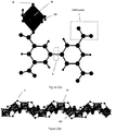
- This overall connectivity affords a porous 3D framework structure with 1D channels ( Fig. 2 ) formed by corner-sharing [AlO 4 (OH) 2 ] octahedra linked via two mutually cis - ⁇ 2 -OH groups.
- the observed cis -configuration of ⁇ 2 -OH groups is responsible for the observed chirality and rigidity of the framework in NOTT-300 (Al).
- the rigidity of the framework structure of NOTT-300 (Al) has been confirmed by in situ variable temperature (100-483 K) PXRD data (Fig.
- NOTT-300 (Al)
- PXRD Thermogravimetric analysis
- TGA confirms NOTT-300 (Al) to have high thermal stability with a decomposition temperature at 400 °C (Fig. S13).
- NOTT-300 (Al) also shows good chemical stability towards air, moisture and common organic solvents, and can be re-hydrated with retention of the framework structure (Fig. S14).
- the framework porosity and surface area of NOTT-300 (Al) is retained upon multiple hydration-dehydration cycles (Fig. S25), thereby confirming the stability of this material to water.
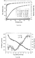
- Al-NOTT-300 exhibits highly selective uptake for CO 2 and SO 2 compared with CH 4 , CO, N 2 , H 2 , O 2 , and Ar.
- the CO 2 selectivities, calculated from the ratio of initial slopes of the isotherm are 100, 86, 180, >10 5 , 70, and 137 for CH 4 , CO, N 2 , H 2 , O 2 , and Ar, respectively.
- the SO 2 selectivities, calculated from the ratio of the initial slopes of the isotherms are 3620, 3105, 6522, >10 5 , 2518, and 4974 for CH 4 , CO, N 2 , H 2 , O 2 , and Ar, respectively.
- thermodynamic parameters Q st and ⁇ S were calculated using the van't Hoff isochore on CO 2 adsorption isotherms measured at 273-303 K.
- the Q st values lie in the range 27.5-28 kJ mol -1 for CO 2 uptakes of 1-2 mmol g -1 and increase continuously thereafter to ⁇ 30 kJ mol -1 at 4.5 mmol g -1 .
- the error in Q st is estimated as 0.05-0.5 kJ mol -1 as shown by the error bars.
- ⁇ S decreases continuously with increasing surface coverage over the whole loading range.
- the error in ⁇ S is estimated as 0.2-1.6 J Kmol -1 as shown by the error bars.
- H 3 BTTri 1,3,5-tris(1 H -1,2,3-triazol-5-yl)benzene
- the isotherm for SO 2 (kinetic diameter 4.11 ⁇ ) exhibits higher uptakes with a maximum capacity of 8.1 mmol g -1 at 273 K and 1.0 bar, representing the highest value observed in the current literature.
- the SO 2 uptake increases sharply at low pressure (below 50 mbar) and reaches saturation at around 0.10 bar, giving a typical type-I isotherm.
- the very rapid uptake observed at low pressure indicates the presence of stronger interactions in NOTT-300 (Al)-SO 2 compared with NOTT-300 (Al)-CO 2 .
- Inelastic neutron scattering is a powerful neutron spectroscopy technique which has been used widely to investigate the H 2 binding interactions within various storage systems by exploiting the high neutron scattering cross-section of hydrogen (82.02 barns).
- this technique cannot directly detect the CO 2 binding interaction within a carbon capture system because the scattering cross-sections for carbon (5.551 barns) and oxygen (4.232 barns) are too small to obtain a clear neutron scattering signal.
- INS and DFT were successfully combined to visualise captured CO 2 molecules within NOTT-300 (Al) by investigating the change in the dynamics of the hydrogen atoms of the local MOF structure, including those of the hydroxyl groups and benzene rings of the ligand ( Fig. 4 ).
- Calculation of the INS spectra from DFT vibrational analysis can be readily achieved, and the DFT calculations relate directly to the INS spectra, and, in the case of solid state calculations, there are no approximations other than the use of DFT eigenvectors and eigenvalues to determine the spectral intensities.
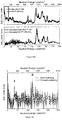
- peak I can be assigned to the O-H groups wagging perpendicular to the Al-O-Al direction, attributed to the presence of the CO 2
- peak II to the wagging of the four aromatic C-H groups on four benzene rings adjacent to each CO 2 molecule in conjunction with the wagging of the OH group along the Al-O-Al direction ( Fig. 4d and film in SI).
- a total of five hydrogen atoms H( ⁇ +) interact cooperatively with the O( ⁇ -) charge centres of CO 2 molecules in the channel via moderate-to-weak hydrogen bonds and supramolecular interactions.
- This PXRD analysis is in excellent agreement with the INS model obtained independently from DFT modelling with regard to both hydrogen-bonding and the combination of supramolecular binding interactions.
- a second CO 2 (II) site has been identified in NOTT-300 (Al) ⁇ 3.2CO 2 studied by PXRD.
- the preferred binding sites for SO 2 molecules within NOTT-300 (Al) have been determined by in situ PXRD.
- the in situ PXRD confirms the retention of the structure of NOTT-300 (Al) upon inclusion and subsequent removal of SO 2 ( Fig. 5a ), thereby confirming the high stability of NOTT-300 (Al) in the presence of corrosive SO 2 .
- the uptake of SO 2 in NOTT-300 (Al) is entirely reversible with no apparent loss of capacity on recycling.
- two distinct, equally-occupied binding sites (I and II) were located within the channel ( Fig.
- OSO ⁇ HC 2.806(14), 2.841(17), 3.111(16), 3.725(18) ⁇ .
- the INS/DFT results are entirely consistent with the PXRD analysis and provide key insights into the dynamics of the NOTT-300 (Al) host upon SO 2 inclusion.
- High resolution powder diffraction data were collected on Beamline I11 at Diamond Light Source by using multi-analysing-crystal detectors (MACs) 28 and an in-situ gas cell system.
- the powder pattern was firstly indexed on a body-centred tetragonal lattice and the independent unit cell parameters were refined using TOPAS. 29
- the structure solution was initially established in space group I 4 1 22 by charge flipping using the program Superflip, 30 and further developed from subsequent difference Fourier analysis using TOPAS.
- the final structure refinement was carried out using the Rietveld method 29 with isotropic displacement parameters for all atoms.
- a total of 40 disordered water molecules per unit cell were found within the pore channel and included in the final structure refinement for NOTT-300 (Al)-solvate.
- SO 2 loading we observe neither major changes to cell parameters nor extra features in the patterns, suggesting that there is no structural phase change during the experiment.
- the occupancy of the first CO 2 site was determined to be 0.865(9) and the second CO 2 site 0.727(7), leading to a total refined CO 2 stoichiometry of 1.592(12) in excellent agreement with the experimental value of 1.6 CO 2 per Al.
- the final stage of the Rietveld refinement involved soft restraints to the C-C bond lengths within the benzene rings. Rigid body refinement was applied to the CO 2 and SO 2 molecules in the pore.
- a TEM image shows the crystals to have uniform morphology of ⁇ 1 ⁇ m plates (Fig. S7a,b), and a high resolution (HRTEM) image confirms the presence of extended crystalline planes (Fig. S7c).
- variable temperature PXRD patterns were collected at 100-483 K for NOTT-300 (Al)-solvate (Fig. S16). Comparison of the PXRD patterns confirms that there is no framework phase transition over this temperature range and the framework of NOTT-300 (Al) remains intact after removal of the water molecules in the channels.
- the lattice parameters were refined via Le Bail methods, and results are summarised in Table S3. The overall change in the unit cell volume is less than 1.0 %, confirming the rigidity of the framework.
- Unit cell parameters for NOTT-300 (Al)-solvate as a function of temperature Table S4 provides a summary of Le Bail refinement results and unit cell parameters for NOTT-300 (Al)-solvate.
- Table S4 a, b ( ⁇ ) c ( ⁇ ) V ( ⁇ 3 ) Unit cell change (%) 100 K 14.78200(30) 11.76100(35) 2569.87(13) 0.000 140 K 14.78821(29) 11.76287(33) 2572.44(12) 0.100 180 K 14.79348(30) 11.76458(34) 2574.64(13) 0.186 220 K 14.80187(30) 11.76717(34) 2578.13(13) 0.321 260 K 14.81512(30) 11.77028(35) 2583.43(13) 0.527 273 K 14.82847(31) 11.77667(37) 2589.50(13) 0.764 303 K 14.83686(30) 11.77726(36) 2592.56(13
- the NOTT-300 (Al)-solvate material was loaded into an IGA and degassed at 120 °C and 10 -10 bar for 24 h to give the fully desolvated NOTT-300 (Al) material.
- a CO 2 adsorption isotherm was then measured at 273 K and up to 1.0 bar (noted as first cycle).
- the desolvated sample was then exposed to high temperature (90-100 °C) water vapour for 1 h as a humidity treatment.
- the hydrated sample was then loaded into IGA and degassed again at 120 °C and 10 -10 bar for 24 h to give desolvated NOTT-300 (Al) material.
- a second CO 2 adsorption isotherm was then measured at 273 K and up to 1.0 bar (noted as the second cycle).
- the vibrational properties of the NOTT-300 were calculated using a combination of density functional theory (DFT) and plane-wave pseudopotential methods as implemented in the CASTEP code, 2 using ultra-soft pseudopotentials with a plane-wave energy cutoff of 380 eV. Calculations were performed under the PBE approximation 3 for exchange and correlation.
- the unit cell used has a volume of 2589.2 ⁇ 3 and contains 144 and 156 atoms for the bare and CO 2 -loaded materials, respectively.
- the wave functions were sampled according to the Monkhorst-Pack scheme with a k-points mesh of spacing ⁇ 0.05 ⁇ -1 .
- the normal modes of the solid were determined from dynamical matrices calculated using finite displacements, by numerical differentiation.
- the INS spectra was the calculated using the aClimax software. 4
- Figure S1 illustrates the potential energy surface along the first vibrational eigenvector of the hydrogen bond between CO 2 and the -OH moieties. At the centre it is clear that the potential would give an unstable configuration from a classical point of view.
- the calculated solution of the Schrödinger equation gives the energy levels at 14.2 and 81 cm -1 .
- the zero point energy is higher than the local maximum so that from a quantum point of view, the system is in a stable equilibrium.
- the MOF material loaded with four CO 2 molecules per unit cell Fig. S1
- corresponding to NOTT-300 (Al) ⁇ 1.0CO 2 8 imaginary frequency modes were found.
- the location of SO 2 molecules in NOTT-300 has been optimised by DFT modelling based on the measured INS spectra.
- the DFT calculation was performed using the same settings as in the case of CO 2 .
- a high symmetry configuration which does not take into account the disorder of SO 2 molecules in the channel, was used.
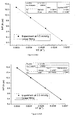
- Figure S29 provides linear fitting of Van't Hoff plots for the CO 2 adsorption isotherms at 0.5, 1.0, 1.5 and 2.0 mmol g -1 loadings.
- K H exp A 0
- Table S6 provides virial fitting results and Henry's constants K H for CO 2 , SO 2 , CH 4 , N 2 , H 2 , O 2 and Ar in NOTT-300 (Al) from isotherm data at 283 K.
- Table S7 Virial fitting results and Henry's constants K H for CO 2 , SO 2 , CH 4 , N 2 , H 2 , O 2 and Ar in NOTT-300 (Al) from isotherm data at 293 K.
- Table S7 CO 2 SO 2 CO CH 4 N 2 H 2 O 2 Ar A 0 / ln( mol g -1 Pa -1 ) - 15.52(3) 5.46(126) - 20.37(2) - 20.23(3) - 20.78(3) n.a.* - 19.98(2) - 20.69(2) K H / mol g -1 Pa -1 1.82(6) x10 -7 235(168) 1.42(2) x10 -9 1.63(4) x10 -9 9.42(22) x10 -10 2.10(5) x10 -9 1.03(2) x10 -9 Fitting R 2 0.997 0.977 >0.999 >0.999 >0.999 >0.999 >0.999 Residual error 0.000030 0.024 0.020 0.013
- Table S8 provides virial fitting results and Henry's constants K H for CO 2 , SO 2 , 5 CH 4 , N 2 , H 2 , O 2 and Ar in NOTT-300 (Al) from isotherm data at 303 K.
- Table S9 provides a summary of gas adsorption selectivity data obtained by two methods: (i) a the ratio of slopes of initial adsorption isotherm plot; (ii) b Henry's Law analysis at 273 K. Table S9 Selectivity ratio Isotherm plot slop Henry's Law analysis CO 2 /CO 86 475 CO 2 /CH 4 100 510 CO 2 /N 2 180 815 CO 2 /H 2 >10 5 >10 5 CO 2 /O 2 70 376 CO 2 /Ar 137 642 SO 2 /CO 3105 >10 5 SO 2 /CH 4 3620 >10 5 SO 2 /N 2 6522 >10 5 SO 2 /H 2 >10 5 >10 5 SO 2 /O 2 2518 >10 5 SO 2 /Ar 4974 >10 5 a This method represents the selectivity at low pressure region (50-350 mbar) and is close to the situation from the direct comparison of gas uptakes. b This method represents the extreme selectivity at zero surface coverage of a given
- Table S10 Summary of gas adsorption selectivity data obtained by two methods: (i) a the ratio of slopes of initial adsorption isotherm plot; (ii) b Henry's Law analysis at 283 K. Table S10 Selectivity ratio Isotherm plot slop Henry's Law analysis CO 2 /CO 67 333 CO 2 /CH 4 57 305 CO 2 /N 2 110 529 CO 2 /H 2 >10 5 >10 5 CO 2 /O 2 54 254 CO 2 /Ar 90 456 SO 2 /CO 3586 >10 5 SO 2 /CH 4 3061 >10 5 SO 2 /N 2 5864 >10 5 SO 2 /H 2 >10 5 >10 5 SO 2 /O 2 2880 >10 5 SO 2 /Ar 4831 >10 5 a This method represents the selectivity at low pressure region (50-350 mbar) and is close to the situation from the direct comparison of gas uptakes. b This method represents the extreme selectivity at zero surface coverage of a given material,
- Table S11 Summary of gas adsorption selectivity data obtained by two methods: (i) a the ratio of slopes of initial adsorption isotherm plot; (ii) b Henry's Law analysis at 293 K. Table S11 Selectivity ratio Isotherm plot slop Henry's Law analysis CO 2 /CO 45 128 CO 2 /CH 4 39 112 CO 2 /N 2 72 193 CO 2 /H 2 >10 5 >10 5 CO 2 /O 2 39 87 CO 2 /Ar 64 177 SO 2 /CO 2854 >10 5 SO 2 /CH 4 2464 >10 5 SO 2 /N 2 4545 >10 5 SO 2 /H 2 >10 5 >10 5 SO 2 /O 2 2490 >10 5 SO 2 /Ar 4070 >10 5 a This method represents the selectivity at low pressure region (50-350 mbar) and is close to the situation from the direct comparison of gas uptakes. b This method represents the extreme selectivity at zero surface coverage of a given material, and therefore is
- Table S12 provides a summary of gas adsorption selectivity data obtained by two methods: (i) a the ratio of slopes of initial adsorption isotherm plot; (ii) b Henry's Law analysis at 303 K. Table S12 Selectivity ratio Isotherm plot slop Henry's Law analysis CO 2 /CO 32 46 CO 2 /CH 4 31 41 CO 2 /N 2 46 73 CO 2 /H 2 >10 5 >10 5 CO 2 /O 2 30 36 CO 2 /Ar 41 54 SO 2 /CO 1586 >10 5 SO 2 /CH 4 1510 >10 5 SO 2 /N 2 2252 >10 5 SO 2 /H 2 >10 5 >10 5 SO 2 /O 2 1458 >10 5 SO 2 /Ar 2002 >10 5 a This method represents the selectivity at low pressure region (50-350 mbar) and is close to the situation from the direct comparison of gas uptakes. b This method represents the extreme selectivity at zero surface coverage of a given material, and therefore is higher than
- a hydrogen bond system is conventionally represented as a linear A-H...B arrangement of a hydrogen donor (A-H) and an acceptor (B). Relevant properties of the different strengths of hydrogen bonds are given in Table C1.
- the hydrogen bond length H ⁇ O is around 2.3 ⁇ ( Figure 4d ), and therefore it can be classed as a moderate-to-weak hydrogen bond.
- the four C-H supramolecular contacts are likely to be of lower energies. Based on this analysis, we view the observed value of Q st as entirely reasonable and consistent with the likely hydrogen bond energies.
- electrostatic Al(III)/XO 2 interactions The high CO 2 uptakes also reflect the relatively narrow pore size of the host which provides strong overlap potentials.
- Table S13 provides properties of strong, moderate and weak H-bonds. Properties Strong H-bonds Moderate H-bonds Weak H-bonds Bond energy (kJ mol -1 4-10 1-3 ⁇ 1 Bond nature mostly covalent mostly electrostatic electrostatic Bond linearity, AH ⁇ B always linear mostly linear sometimes linear Bond length A-H ( ⁇ ) 1.2 to 1.5 ca 1.0 ca 1.0 Bond length H ⁇ B ( ⁇ ) 1.2 to 1.5 1.5 to 2.2 2.2 to 3.2 Bond length A ⁇ B ( ⁇ ) 2.2 to 2.5 2.5 to 3.2 3.2 to 4.0
- Biphenyl-3,3',5,5'-tetracarboxylic acid (0.015 g, 0.045 mmol), In(NO 3 )-(H 2 O) 5 (0.014 mg, 0.045 mmol) and piperazine (7.0 mg, 0.081 mmol) were mixed and dispersed in DMF/MeCN mixture (1.3 mL, 1:0.3 v/v).
- the white slurry was acidified with dilute nitric acid (5 %, 0.3 mL) and heated to 100 °C. Upon reaching 60 °C the white slurry was observed to fully dissolve resulting in a colourless solution followed by precipitation of a white crystalline powder which was washed sequentially with DMF and dried briefly in air.
- Powder diffraction data confirm that the parent MOF NOTT-300 (In)-solv is iso-structural to NOTT-300(Al)-solv. Yield: 20 mg (75 %). Elemental analysis (% calc/found): [In 2 (C 16 H 6 O 8 ) 2 ⁇ (DMF) 0.75 ⁇ (H 2 O) 1.75 (C 33.02/33.02, H 2.20/2.53 N 1.58/1.58).
- Biphenyl-3,3',5,5'-tetracarboxylic acid (0.015 g, 0.045 mmol) and SbCl3 (0.010 mg, 0.045 mmol) were mixed and dispersed in DMF/MeCN mixture (1.3 mL, 1:0.3 v/v).
- the white slurry was acidified with dilute nitric acid (5 %, 0.3 mL) and heated to 100 °C. Upon reaching 60 °C the white slurry was observed to fully dissolve resulting in a colourless solution followed by precipitation of a white crystalline powder which was washed sequentially with DMF and dried briefly in air.
- Chromium nitrate, Cr(NO 3 ) 3 ⁇ 9H 2 O, (0.36g, 0.9mmol) was dissolved in water (10mL), biphenyl-3,3',5,5'-tetracarboxylic acid (0.06g, 0.18mmol) was then added.
- Piperazine (0.1g) was added followed by addition of 2.8 M nitric acid (2 mL).
- the reaction mixture was transferred to a 2 mL autoclave which was sealed and heated to 210 °C for 72-96 h.
- the resulting powder product was separated by filtration and washed with water.
- NOTT-300(Ga 2 ) ⁇ [Ga 2 (OH) 2 (C 16 H 6 O 8 )] ⁇ was synthesised under solvothermal conditions by reacting biphenyl-3,3',5,5'-tetracarboxylic acid (0.02 g, 0.06 mmol) and gallium nitrate, Ga(NO 3 ) 3 •xH 2 O, (0.1 g, 0.36 mmol), in a mixture of DMF, THF and water (8 mL, 2:5:1, v/v) which was then acidified with 5-15 drops of hydrochloric acid and heated at 75°C for 72 h.
- the Ga(III) ion is octahedrally coordinated via six O-donors: four from carboxylate groups and two from bridging hydroxyl groups ⁇ 2 -OH which are aligned in cis confirmation.
- a mixed Ga-Fe material was obtained using a similar procedure but incorporating stoichiometric mixtures of gallium nitrate Ga(NO 3 ) 3 •xH 2 O and iron nitrate Fe(NO 3 ) 3 •9H 2 O in the following ratios: [Ga 1.87 Fe 0.13 (OH) 2 (C 16 H 6 O 8 )]: (0.09g, 0.34mmol), (0.007g, 0.18mmol); [Ga 1.79 Fe 0.21 (OH) 2 (C 16 H 6 O 8 )]: (0.083g, 0.32mmol), (0.015g, 0.036mmol); [Ga 1.55 Fe 0.45 (OH) 2 (C 16 H 6 O 8 )]: (0.078g, 0.31mmol), (0.022g, 0.054mmol), respectively.
- Figure 27 illustrates a gas capture apparatus comprising a container 10 in which the MOF 40 is contained.
- the container 10 may have one or more inlets 20 in which gases may enter the container 10.
- the gases may be flue gases produced be a power station or from some other combustion or industrial processes for example in the production of iron, steel, ammonia and cement.
- the MOF 40 may be regenerated.
- the MOF 40 in container 10 may be heated using a heater 80 so as drive-off adsorbed gases and regenerate the MOF 40 for its re-use.
- desorption of gasses from the MOF 40 may proceed through the application of vacuum to the vessel containing the MOF.
- the container 10 may be in fluid connection with a vacuum pump 50 configured to draw off the gases (eg.
- An inlet valve 60 may be closed and an outlet valve 70 may be opened whilst the MOF 40 is being heated so that the captured are not released back into the flue. Or a vacuum may be applied through valve 70 to desorb the gas from MOF 40 where heating is not used. Whilst the apparatus is being used to capture gases the inlet valve 60 will be open and the outlet valve 60 may be closed.
- the MOF may also be used as part of a cartridge system in which a cartridge 90 (or other container/ mechanism to support or hold the MOF) is placed in the gas stream to be processed. The cartridge 90 may then be removed from the gas stream so as to be regenerated off-line from the gas stream.
- Figure 28(a) illustrates such a cartridge 90 placed within a gas stream.
- the cartridge 90 may cover the majority of the cross section of a conduit 100 carrying the gas stream or may be adapted to cover substantially all of the conduit cross section as illustrated in Figure 28(a) .
- the conduit 100 may form both the inlet 20 and the outlet 30 (as illustrated in Figure 28(a) ).
- Such a cartridge system may be useful for anaesthetic systems and exhausts systems from combustion.
- Figure 28(b) illustrates a cartridge at the end of a flue or exhaust pipe. In this case the side or sides of the cartridge distal from the flue may act as the outlet 30.
- TEM samples were prepared by casting several drops of a suspension of the NOTT-300 solvate complex in water onto copper-grid mounted lacy carbon film before drying under a stream of nitrogen.
- INS spectra were recorded on the TOSCA spectrometer at the ISIS Facility at the Rutherford Appleton Laboratory (UK) for energy transfers between ⁇ -2 and 500 meV. In this region TOSCA has a resolution of ⁇ 1% ⁇ E / E.
- the desolvated NOTT-300 (Al) sample was loaded into a cylindrical vanadium sample container with an annealed copper vacuum seal and connected to a gas handling system. The sample was degassed at 10 -7 mbar and 140 °C for 1 day to remove any remaining trace guest water molecules. The temperature during data collection was controlled using a helium cryostat (7 ⁇ 0.2 K).
- the loading of CO 2 was performed at room temperature in order to ensure that CO 2 was present in the gas phase when not adsorbed and also to ensure sufficient mobility of CO 2 inside the crystalline structure of NOTT-300 (Al).
- the loading of H 2 was performed at 40-50 K in order ensure that H 2 was adsorbed into NOTT-300 (Al). Subsequently, the temperature was reduced to below 10 K in order to perform the scattering measurements with the minimum achievable thermal motion for CO 2 or H 2 . Background spectra (sample can plus NOTT-300 (Al)) were subtracted to obtain the difference spectra.
- INS was used to study the binding interaction and structure dynamics in this case, because it has several unique advantages:
Landscapes
- Chemical & Material Sciences (AREA)
- Organic Chemistry (AREA)
- Engineering & Computer Science (AREA)
- Analytical Chemistry (AREA)
- Chemical Kinetics & Catalysis (AREA)
- General Chemical & Material Sciences (AREA)
- Oil, Petroleum & Natural Gas (AREA)
- Inorganic Chemistry (AREA)
- Mechanical Engineering (AREA)
- General Engineering & Computer Science (AREA)
- Solid-Sorbent Or Filter-Aiding Compositions (AREA)
Description
- This invention relates to coordination polymers, and in particular to metal organic frameworks, and the use of such metal organic frameworks for gas capture. The invention also relates to a method of making such metal organic frameworks
- It is widely accepted that it is imperative that emissions of carbon dioxide (CO2) and other acidic gases such as sulphur dioxide (SO2) and nitrogen dioxide (NO2) created by human activity is reduced in order to limit the negative effects of global climate change. One particular challenge is the reduction of CO2 emissions from flue gases produced by large industrial plant and coal-fired power stations. Current state-of-the-art technology uses aqueous solutions of organic amines for post-combustion CO2 capture, a so called "amine-scrubbing mechanism". These amine functionalised capture systems dominate this area, due to potential formation of carbamates via H2N(δ-)•••C(δ+)O2 electrostatic interactions, thereby trapping CO2 covalently. However, there are considerable costs associated with this process due to the substantial energy input required for the regeneration of the amine solutions, this is in addition to their highly corrosive and toxic nature. Thus there is a negative environmental penalty associated with the use of amines which significantly limits their long-term applications. There are, therefore, powerful drivers to develop efficient strategies to remove CO2 using alternative materials that simultaneously have high adsorption capacity, high CO2 selectivity and high rates of regeneration at an economically viable cost. Traditional microporous solid-state materials such as zeolites, porous membranes and activated carbon can effectively adsorb and remove CO2. However, the low separation efficiency and poor selectivity of these materials significantly limits their real-world applicability. Therefore there is a need to develop new materials with high CO2 storage capacity and selectivity that can be produced at an economically and environmentally viable cost.
- Metal organic frameworks (MOF), a relatively new class of porous materials, are built up of metal cation nodes bridged by organic ligand linkers and they have huge potential to deliver significant breakthroughs in carbon capture. The advantages of MOFs over existing technologies include: (i) they can store greater amounts of CO2 than other classes of porous materials, including commercial materials such as zeolite 13X and activated carbon; (ii) their surface areas and pore volume can be adjusted via appropriate crystal engineering and topological connections in order to maximise the CO2 adsorption capacity; (iii) the pore surface and environment can be fine controlled and tuned via variation of organic and inorganic components that constitute the framework in order to enhance CO2 capacity and selectivity; (iv) the adsorbed CO2 molecules can be readily released via reduction of the pressure, i.e. the capture system can be regenerated without additional heating input; (v) the extended crystalline structure of MOF materials gives a unique opportunity to determine and study the mechanisms of carbon capture and storage (CCS) using advanced diffraction techniques.
- US patent application
US2007/0068389 describes the use of a number of Copper and Zinc based MOF materials to store carbon dioxide at room temperature. These materials show high uptakes of CO2 and have been shown to perform better than zeolites and activated carbons as carbon dioxide storage media inside gas canisters. - However, there is a need for metal-organic frameworks with:
- a) higher CO2 adsorption capacity;
- b) selective adsorption of acidic gases & VOCs;
- c) improved framework stability;
- d) and improved ease of manufacture.
- Mendt et al, J. Phys. Chem. C 2010, 114, 19443-19451 describes the structural phase transitions and thermal hysteresis in the metal-organic framework compound MIL-53 as studied by electron spin resonance spectroscopy.
- Finsy et al, Microporous and Mesoporous Materials, 120 (2009) 221-227 describes the separation of CO2/CH4 mixtures with the MIL-53(Al) metal-organic framework.
- According to a first aspect of the present invention, there is provided a metal organic framework comprising a metal (III) ion (M) and a biphenyl-3, 3',5,5' tetracarboxylate organic ligand, wherein more than one hydroxy ligand are present about the metal (III) ion, and wherein hydroxyl ligands point into the channels of the framework. According to a second aspect of the present invention, there is provided a method for producing a metal-organic framework according to the first aspect, the method comprising the steps of:
- a. providing a metal salt;
- b. providing an organic ligand;
- c. mixing the metal salt and the organic ligand; and
- d. reacting the metal salt with organic ligand to form a metal-organic framework,
- According to a third aspect of the present invention, there is provided a use of a metal organic framework according to the first aspect to capture one or more of CO2 and SO2 by the formation of a weak electrostatic interaction between the CO2 and/or SO2 molecule and the metal organic framework.
- According to a fourth aspect of the present invention, there is provided a use of a metal organic framework according to the first aspect to capture NO2 by the formation of a weak electrostatic interaction between the NO2 molecule and the metal organic framework.
- According to a fifth aspect of the present invention, there is provided a use of a metal organic framework according to the first aspect to capture a C2Hn (n = 2, 4, 6) molecule by the formation of a weak electrostatic interaction between the C2Hn molecule and the metal organic framework.
- Also described herein is a solid crystalline metal-organic framework comprising of a metal ion, preferably one of Al(III), Cr(III), Sb(III), In(III), Ga(III), and Fe(III) and an organic ligand. Wherein said organic ligand is a polycarboxylate. Typically, the organic ligand is a tetracarboxylate; preferably a biphenyl tetracarboxylate. The metal ion (M) is octahedrally coordinated as the moiety MO4(OH)2 via six oxygen atoms. Four of the oxygen atoms are from the carboxylate groups and two of the oxygen atoms are from the hydroxyl groups.
- The resulting crystalline MOF structure has channels between the repeating units of the metal-hydroxyl[tetracarboxylate] complexes. Preferably, the metal organic framework incorporates a channel decorated by metal hydroxyl groups and phenyl rings that are available to form electrostatic interactions between XO2 (X= C, S, N) gas molecules or small hydrocarbon molecules, e.g. VOCs. The hydrocarbon molecule may be one or more of C2H2, C2H4, C2H6 or one of the isomers of xylene. Gases, such as methane, nitrogen, hydrogen, carbon monoxide, argon and oxygen do not interact with the framework and thus are not adsorbed by the material.
- The weak interactions between the captured gas and the MOF material lead to low isoteric heats of absorption, thereby reducing the amount of energy required to drive off the captured gas and regenerate the vacated MOF material. This weak interaction is advantageous when compared to the formation of chemical bonds between amine substrates and gas molecules in amine-containing solutions/solids. Typically, in conventional amine functionalised MOFs, the isoteric heats of adsorption are 40-90 kJ mol-1 for physisorption and 85-105 kJ mol-1 for chemisorption. These high values for chemisorption lead to a substantial energy penalty to release adsorbed CO2 from the metal-organic structure. Therefore a large energy penalty is avoided in using the MOF materials of the type described herein. Thus there may be applications these MOFs in industrial scale capture and separation of acidic gases due to the potentially significant energy savings available.
- In such systems the CO2 or other gases are released from the MOF during the MOF regeneration process and extracted as a stream of gas. The extracted gas can then be compressed for storage or transport. Post Combustion Capture (PCC) of acidic gases from flue gas and sequestration/separation of these gases is relevant in the following industrial sectors: power generation, iron and steel production, ammonia production, cement production, natural gas sweetening, syngas gas purification.
- The MOF materials have also shown adsorption of short chain hydrocarbons gases such as ethylene and acetylene. Notably a preference for acetylene adsorption over ethylene and ethane has been observed and this selectivity is an important property which may make these MOFs suitable candidates for gas separation. In some embodiments the hydrocarbon may also be a substituted hydrocarbon such as a halogenated hydrocarbon. Furthermore, embodiments of the invention may also be applied to the capture of other small molecules such as "C3" molecules (i.e. molecules having three carbon atoms). Embodiments of the invention may also be used to capture other Volatile Organic Compounds (VOCs).
- Anaesthetic systems comprise of a rebreather system in which CO2 is scrubbed from the anaesthetic gas during the cycling of the gas. Currently soda lime is used for this process. According to the present invention the MOF may be used for scrubbing the CO2 from the recycled gas. The potential for MOFs in this area is the reduction of medical/chemical waste as soda lime has a finite life and, once depleted, it is disposed of as contaminated waste. Moreover, there is known decomposition of the anaesthetic gases due to reaction with the caustic soda lime which may lead to patient inhalation of potentially harmful by-products. Additives are used to prevent this. NOTT-300 may provide CO2 scrubbing where no reaction between the anaesthetic gas and the MOF material is observed.
- The present invention may also find use in: diving rebreathers (i.e. SCUBA); personal protective equipment (PPE), gas masks etc. (acidic gas scrubbing); military applications (PPE, gas scrubbing air in closed environments e.g. bunkers, submarines etc.), syn-gas purification; driving the water gas shift to completion for more efficient production of hydrogen from CO and water; mixed matrix materials i.e. the impregnation of MOFs into membranes for gas separation.
- The organic ligand used in the first and second aspects of the invention is biphenyl-3,3',5,5'-tetracarboxylic acid.
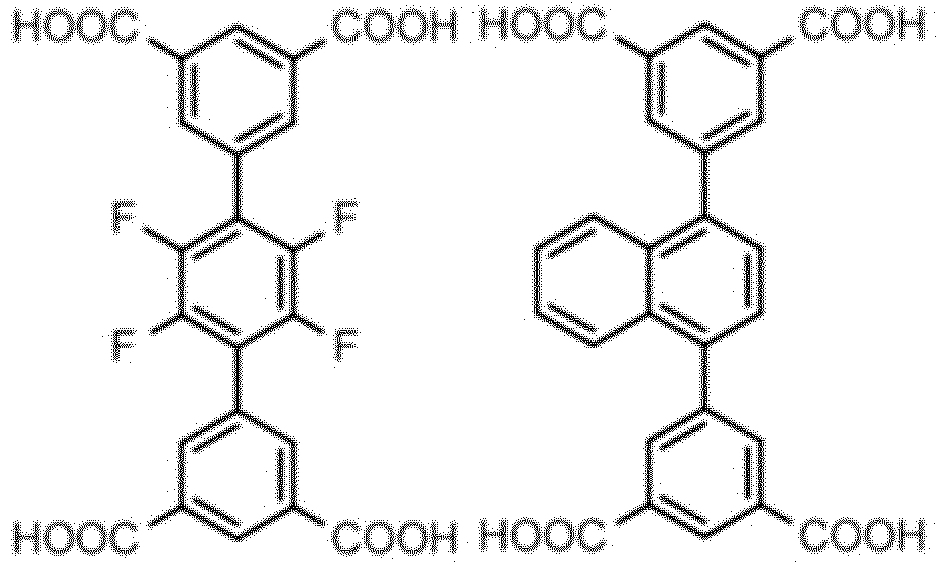
- Other organic ligands described herein more generally include a tetracarboxylic acid; a phenyl tetracarboxylic acid; and a phenyl tetracarboxylic acid selected from the group having the general formula (I):


- Preferably, two of A,B,C,D, or E are -COOH and two of F, G, H, I or J are -COOH. Alternatively, when only one of A, B, C, D, or E are -COOH and only one of F, G, H, I or J are -COOH, then two of T, S, U and V are -COOH or

- The biphenyl-3,3',5,5'-tetracarboxylic acid organic ligand used in the first and second aspects of the invention has the structure:

- Other organic ligands described herein more generally include:



- In an embodiment of the invention the MOF is one of: M2(OH)2(C16O8H6); where M = Al, In, Sb, Ga, Cr being a biphenyl tetracarboxylate ligand, for example biphenyl-3, 3',5,5' tetracarboxylate.
- In one particular example the MOF contains more than a single type metal (III) ion preferably the metal ion being selected from Al(III), Cr(III), Sb(III), In(III), Ga(III), and Fe(III) For example the complex may comprise of both gallium and iron and have the formula (Ga2-xFex)(OH)2(C16O8H6) with x being greater than zero.
- As discussed hereinbefore, in a second aspect, the present invention provides a method for producing a metal-organic framework according to the first aspect, the method comprising the steps of:
- a. providing a metal salt;
- b. providing an organic ligand;
- c. mixing the metal salt and the organic ligand; and
- d. reacting the metal salt with organic ligand to form a metal-organic framework,
- The synthesis of the aluminum MOF is particularly advantageous as it requires water as the only solvent and avoids the use of toxic solvents such as N,N-dimethylformamide that are commonly used to synthesise MOF materials. Additionally aluminium is a relatively cheap metal in comparison to some other metal (III) ions.
- For the MOF complex Al2(OH)2(C16O8H6), the method may comprise reacting biphenyl-3,3',5,5'-tetracarboxylic acid with Al(NO3)3.9H2O; for the MOF complex In2(OH)2(C16O8H6) the method may comprises reacting biphenyl-3,3',5,5'-tetracarboxylic acid with In(NO3)3.5H2O; for the MOF complex Cr2(OH)2(C16O8H6) and the method comprises reacting biphenyl-3,3',5,5'-tetracarboxylic acid with Cr(NO3)3.9H2O.
- In one particular example the MOF contains more than one single type metal (III) ion preferably with the metal ion(s) being selected from Al(III), Cr(III), Sb(III), In(III), Ga(III), and Fe(III). For example the complex may comprise of both gallium and iron and have the formula (Ga2-xFex)(OH)2(C16O8H 6 ) with x being greater than zero. In one example the MOF complex is (Ga2-xFex)(OH)2(C16O8H 8 ), x >0, and the method comprises reacting a stoichiometric mixture of gallium nitrate, iron nitrate, hydrochloric acid and biphenyl-3,3',5,5'-tetracarboxylic acid under solvothermal conditions.
- In one embodiment the invention provides use of the MOF to capture two different gases in one pore of the MOF.
- As discussed hereinbefore, in a third aspect, the present invention provides a use of a metal organic framework according to the first aspect to capture one or more of CO2 and SO2 by the formation of a weak electrostatic interaction between the CO2 and/or SO2 molecule and the metal organic framework.
- As discussed hereinbefore, in a fourth aspect, the present invention provides a use of a metal organic framework according to the first aspect to capture NO2 by the formation of a weak electrostatic interaction between the NO2 molecule and the metal organic framework.
- As discussed hereinbefore, in a fifth aspect, the present invention provides a use of a metal organic framework according to the first aspect to capture a C2Hn (n = 2, 4, 6) molecule by the formation of a weak electrostatic interaction between the C2Hn molecule and the metal organic framework.
- The above-mentioned and other features and objects of this invention, and the manner of obtaining them, will become more apparent and the invention itself will be better understood by reference to the following description of embodiments of the invention taken in conjunction with the accompanying drawings, wherein:
-
Figure 1 is a schematic view comparing of gas binding interactions in amine-functionalised materials and in hydroxyl-functionalised materials; -
Figure 1(a) illustrates the bonds formed between carbon dioxide molecules and an amine group as would be present in known amine functionalised systems. In such systems the first CO2 molecule interacts with the NH2 group through a side-on mode and the second CO2 molecules interacts with the first CO2 molecule through an end-on mode. Such interactions result in high isosteric heats of adsorption particularly when there is direct bond formation between the N-centre of the amine group and the electro-positive C-carbon centre of CO2 (i.e. chemisorption); -
Figure 1(b) illustrates the hydrogen bonds present between a hydroxyl functionalised material and CO2 molecules; -
Figure 1(c) illustrates the hydrogen bonds present between a hydroxyl functionalised material and SO2 molecules; -
Figure 1(d) shows the anticipated interactions believed to be the rationale behind the high NO2 adsorption capacities observed; -
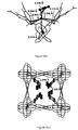
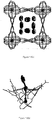
Figure 2 provides views of the structure for NOTT-solvate. The structure was solved from high resolution PXRD data by ab initio methods for NOTT Al-solvate and has been found to be correct for equivalent compounds using other metal (III) ions.Figure 2(a) illustrates the coordination environment for ligand L4- and M(III) centre.Figure 2(b) illustrates a corner-sharing extended octahedral chain of [MO4(OH)2]∞. The µ2-(OH) groups are highlighted as a space-filling model, and linked to each other in a cis-configuration.Figure 2(c) illustrates the 3D framework structure with channel formed along the c-axis. The free water molecules in the channel are omitted for clarity.Figure 2(d) is a schematic view of the square-shaped channel. The µ2-(OH) groups protrude into the centre of the channel from four directions. [MO4(OH)2] groups are illustrated as octahedral. A µ2-OH group is an -OH group that is coordinated to two metal centres, i.e. it is a bridging -OH group; -
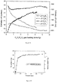
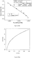
Figure 3 (a) is a graph comparison of the gas adsorption isotherms for NOTT-300 (Al) at 273 K and 1.0 bar for a selection of gases; -
Figure 3 (b) is a graph illustrating the variation of isosteric enthalpy (Qst ) and entropy (ΔS) of CO2 adsorption; -
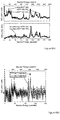
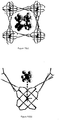
Figure 4 shows in situ inelastic neutron scattering (INS) spectra and simulated CO2 positions in the pore channel of NOTT-300 (Al); -
Figures 4 (a) shows in situ inelastic neutron scattering (INS) spectra and simulated CO2 positions in the pore channel. This diagram shows a comparison of the experimental (top) and DFT simulated (bottom) INS spectra for bare and CO2-loaded NOTT-300 (Al). -
Figures 4 (b) is a difference plot for experimental INS spectra of bare and CO2-loaded NOTT-300 (Al). Two distinct energy transfer peaks are labelled as I and II. -
Figures 4 (c) is a view of the structure of NOTT-300 (Al)·3.2CO2 obtained from PXRD analysis. The adsorbed CO2 molecules in the pore channel are highlighted by the use of ball-and-stick mode. The carbon atom of second site of CO2 is shown.. The dipole interaction between CO2 (I, II) molecules are shown[O=C=O···CO2 = 3.920 Å]. -
Figure 4 (d) is a detailed view of the role of the -OH and -CH groups in binding CO2 molecules in a "pocket-like" cavity. The model was obtained from DFT simulation. The modest hydrogen bond between O(δ-) of CO2 and H(δ+) from the Al-OH moiety is shown, [O···H = 2.335 Å]. The weak cooperative hydrogen bond interactions between O(δ-) of CO2 and H(δ+) from -CH is shown, [O···H = 3.029, 3.190 Å, each occurring twice]. Each O(δ-) centre therefore interacts with five different H(δ+) centres. -
Figure 5 shows in-situ synchrotron X-ray powder diffraction patterns and refined SO2 positions in the pore channel of NOTT-300 (Al); -
Figure 5 (a) is a comparison of the powder diffraction patterns for original, evacuated, SO2-loaded, and final desolvated samples at 273 K. -
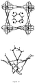
Figure 5 (b) illustrates the crystal structure of NOTT-300 (Al)·4.0SO2 obtained from Rietveld refinement of data on SO2-loaded material at 1.0 bar. The adsorbed SO2 molecules in the pore channel are highlighted by the use of ball-and-stick mode. The sulphur atom of second site of SO2 is labelled with an asterisk. -
Figure 5 (c) provides a detailed view of the role of the -OH and -CH groups in binding SO2 molecules into a distorted "pocket-like" cavity. The moderate hydrogen bond between O(δ-) of SO2(I) and H(δ+) from -OH is shown as the a vertical dashed line, [O···H = 2.376(13) Å]. The weak cooperative hydrogen interaction between O(δ-) of SO2 and H(δ+) from -CH is shown, [O···H = 2.806(14), 2.841(17), 3.111(16), 3.725(18) Å]. Therefore, each O(δ-) centre is interacting with five different H(δ+) centres simultaneously. The bond distance between S(δ+) of SO2(I) and O(δ-) of SO2(II) is 3.34(7) Å. -
Figure 6 shows in situ inelastic neutron scattering (INS) spectra and simulated SO2 positions in the pore channel of NOTT-300 (Al); -
Figure 6 (a) provides a comparison of the experimental (top) and DFT simulated (bottom) INS spectra for bare and SO2-loaded NOTT-300; -
Figure 6 (b) is a difference plot for experimental INS spectra of bare and SO2-loaded NOTT-300. Two distinct energy transfer peaks are labelled as I and II; -
Figure 6 (c) is a detailed view of the role of the -OH and -CH groups in binding SO2 molecules in a "pocket-like" cavity. Model was obtained from DFT simulation. The adsorbed SO2 molecules in the pore channel are highlighted by the use of ball-and-stick mode. The modest hydrogen bond between O(δ-) of SO2 and H(δ+) from the Al-OH moiety is shown as the vertical dashed line, [O···H = 2.338 Å]. The weak cooperative hydrogen bond interactions between O(δ-) of CO2 and H(δ+) from -CH is shown, [O···H = 2.965-3.238 Å]. Each O(δ-) centre therefore interacts with five different H(δ+) centres; -
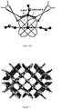
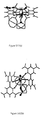
Figure 7 is a three dimensional representation of the pore structure of a MOF according to an embodiment of the invention; -
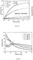
Figure 8 is a graph comparing the gas adsorption isotherms of various hydrocarbons with NOTT-300 (Al). The corresponding desorption isotherms exhibit full reversibility without hysteresis demonstrating the stability of the MOF in the hydrocarbon environments. -
Figure 9 shows graphs of the gas selectivity ratio for C2H2/C2H4 with NOTT-300 (Al) as a function of gas pressure at various temperatures. Also see Table A provides derived values of extreme selectivity ratios for C2H2/C2H4 at 0 mbar. -
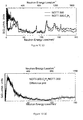
Figure 10 shows INS spectra for adsorbed C2H2 and C2H4 in NOTT-300(Al) -
Figure 11 shows INS spectra for condensed phase C2H2. -
Figure 12 shows in situ diamond powder diffraction patterns for C2H2-loaded NOTT-300. -
Figure 13 is an illustration of the structure of NOTT-300 (Al).3C2H2; -
Figure 14 is an illustration of the structure of NOTT-300 (Al).1C2H4; -
Figure 15 is an illustration of the structure of NOTT-300 (Al).1C2H6; -
Figure 16 illustrates INS spectra for C2H2,4; -
Figure 17 is an illustration of the structure of NOTT-300 (Al).2.4C2H2.0.7C2H4; -
Figure 18 is an illustration of some structures of NOTT-300 (Al) with adsorbed acetylene and/or ethylene; -
Figure 19 provides graphs of enthalpy and entropy versus gas pressure for the adsorption of C2H2 and C2H4; -
Figure 20 illustrates a gas adsorption isotherm of NO2 with NOTT-300 (Al) at 295K. -
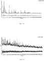
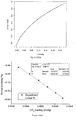
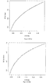
Figure 21 illustrates X-ray diffraction data for NOTT-300 (In).Figure 21(a) is a broad 2Th degree spectrum whereasFigure 21(b) is a scaled up spectrum andFigure 21 (c) is an even further scaled up spectrum. -
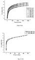
Figure 22(a) illustrates the gas adsorption isotherms of NOTT-300 (Cr) for CO2 at various temperatures. It can be seen that there is a high uptake of CO2; -
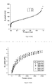
Figure 22(b) shows the CO2 gas adsorption isotherm for NOTT-300 (Cr) at 198K to more clearly show a high degree of hysteresis between adsorption and desorption thereby indicating the stability of the complex in carbon dioxide gas; -
Figure 22(c) shows the N2 gas adsorption isotherm for NOTT-300 (Cr). It can be seen that the uptake of N2 here is higher than for NOTT-300 (Al); -
Figure 22(d) shows the CH4 gas adsorption isotherm for NOTT-300 (Cr); -
Figure 22(e) shows the H2 gas adsorption isotherm for NOTT-300 (Cr). It can be seen that the uptake of these gases is very low compared to CO2 and SO2. All the isotherms show good hysteresis of between adsorption and desorption of the gases demonstrating the stability of the compound in the gases. -
Figure 23 is a packing diagram for NOTT-300 (Cr) illustrating that this MOF is isostructural with NOTT-300 (Al) with 1-dimensional square pore channels. -
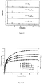
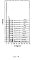
Figure 24 illustrates the powder X-ray diffraction data (PXRD) patterns for (Ga2-xFex)MOF(x = 0, 0.13, 0.21, 0.45). The patterns confirm that the parent MOF NOTT-300 (Ga)-solvated is iso-structural to NOTT-300(Al)-solvated. -
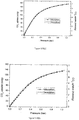
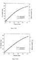
Figure 25 shows the CO2 adsorption isotherms for NOTT3-00(Ga2-xFex) (x = 0, 0.13, 0.21, 0.45) at 195 K at pressures up to 1 bar. It can be seen that the degree of CO2 uptake is dependent on the molar ratio of Ga and Fe used in the MOF. -
Figure 26 shows the CO2 adsorption isotherms for NOTT-300(Ga2-xFex) (x = 0, 0.13, 0.21, 0.45) at 293 K at pressures up to 20 bar. -
Figure 27 is a schematic illustration of an apparatus for gas storage. - Figure S1 is a graph showing the potential energy surface along the first vibrational eigenvector of the hydrogen bond between CO2 and an OH group of NOTT-300 (Al) ;
- Figure S2 (a) illustrates PXRD patterns for the Rietveld refinement of the as-synthesized NOTT-300 (Al)-solvate [λ = 0.826949(2) Å].
- Figure S2 (b) illustrates PXRD patterns for higher angle data (2θ = 22.5-55°) scaled up to show the quality of the fit between the observed and the calculated patterns.
- Figure S3 (a) illustrates PXRD patterns for the Rietveld refinement of the CO2-loaded NOTT-300 (Al)·3.2CO2 [λ = 0.826126(2) Å].
- Figure S3 (b) illustrates PXRD patterns for higher angle data (2θ = 22.5-60°) scaled up to show the quality of fit between the observed and the calculated patterns.
- Figure S4 (a) illustrates PXRD patterns for the Rietveld refinement of the SO2-loaded NOTT-300 (Al)·4SO2 [λ = 0.826126(2) Å].
- Figure S4 (b) illustrates PXRD patterns for higher angle data (2θ = 22.5-55°) scaled up to show the quality of fit between the observed and the calculated patterns.
- Figure S5 (a) provides a comparison of the powder diffraction patterns for original, evacuated, SO2-loaded, and final desolvated samples at 273 K.
- Figure S5 (b) shows the powder diffraction patterns for higher angle data (2θ = 4.5-25°) has been scaled up to show the changes upon SO2 inclusion. NOTT-300 (Al) retains crystallinity after removal of SO2.
- Figure S6 (a) shows powder X-ray diffraction patterns for original, evacuated, CO2-loaded, and final desolvated samples at 273 K.
- Figure S6 (b) shows powder X-ray diffraction patterns for higher angle data (2θ = 4.5-25°) has been scaled up confirming that NOTT-300 (Al) retains crystallinity on removal of CO2.
- Figure S7 are TEM images for NOTT-300 (Al)-solvate. TEM images confirm that the crystals have uniform morphology (∼1 µm plates)
- Figure S8 provides a view of the structure of NOTT-300 (Al)-solvate along the a-axis.
- Figure S9 provides a view of the structure of NOTT-300 (Al)·1.0CO2 along the c-axis (a) and a-axis (b). The structure was obtained by DFT simulation. The adsorbed CO2 molecules in the pore channel are highlighted by the use of spacing filling style.
- Figure S10 provides detailed views of -OH and -CH groups binding CO2 in the "pocket" cavity of NOTT-300 (Al)·1.0CO2. Views along (a) the a-axis, (b), the b-axis and (c) the c-axis. The moderate hydrogen bond between O(δ-) of CO2 and H(δ+) of-OH is shown, [O···H = 2.335 Å]. The weak cooperative hydrogen bond between O(δ-) of CO2 and H(δ+) from -CH is shown, [O···H = 3.029, 3.190Å with each occurring twice]. Therefore, each O(δ-) centre interacts with five different H(δ+) centres.
- Figure S11 provides a view of the structure of NOTT-300 (Al)·4.0SO2 along the c-axis (a) and a-axis (b). The structure was obtained by Rietveld refinement of high resolution powder diffraction data collected for NOTT-300 (Al)·4.0SO2. The adsorbed SO2 molecules in the pore channel are highlighted by the use of spacing filling style
- Figure S12 provides detailed views of -OH and -CH groups binding SO2 in the "pocket" cavity of NOTT-300 (Al)·4.0SO2. Views along (a) the a-axis, (b), the b-axis and (c) the c-axis. The modest hydrogen bond between O(δ-) of SO2(I) and H(δ+) from -OH is shown, [O···H = 2.376(13) Å]. The weak cooperative hydrogen bond between O(δ-) of SO2 and H(δ+) from -CH is shown, [O···H = 2.806(14), 2.841(17), 3.111(16), 3.725(18) Å]. Therefore, each O(δ-) centre is interacting with five different H(δ+) centres. The bond distance between S(δ+) of SO2(I) and O(δ-) of SO2(II) is 3.34(7) Å is shown. The S-O bond distances are 1.481(4) and 1.500(8) Å for SO2(I) and SO2(II), respectively. The <O-S-O angles are 117.5(11) and 109.1(9) ° for SO2(I) and SO2(II), respectively.
- Figure S13 is a Thermo Gravimetric Analysis (TGA) plot shows that the as-synthesised sample NOTT-300 (Al)-solvate loses solvent rapidly between 30 and 100 °C, with a plateau observed from 100-200 °C indicating no further weight loss to give NOTT-300 (Al). The weight loss of 20.0 % from NOTT-300 (Al)-solvate between 20 and 200 °C corresponds to a loss of three water molecules per aluminium (calc. 20.6 wt.%). Above 400°C NOTT-300 (Al) starts to decompose rapidly.
- Figure S14 illustrates PXRD spectra for NOTT-300(Al) under different chemical environments [λ=0.826134(2) Å];
- Figure S15 shows graphs comparing of unit cell parameters of NOTT-300(Al) under different chemical environments and;
- Figure S16 illustrates variable temperature PXRD spectra for NOTT-300(Al) -solvate (λ = 1.54056 Å);
- Figure S17 is a graph comparing of unit cell parameters for NOTT-300(Al)-solvate as a function of temperature;
- Figure S18 illustrates H2, N2 and Ar sorption isotherms at 77 or 87 K for NOTT-300 (Al). No significant uptake was observed for these adsorption isotherms.
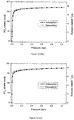
- Figure S19 CO2 adsorption and desorption isotherms for NOTT-300 (Al) at (a) 273 K, (b) 283 K, (c) 293 K and (d) 303 K.
- Figure S20 illustrates high pressure CO2 adsorption and desorption isotherms at 273 K for NOTT-300 (Al).
- Figure S21 is a pore size distribution (PSD) plot and cumulative pore volume for NOTT-300 (Al). Data were calculated the CO2 adsorption isotherm at 273 K using DFT/Monte Carlo methods.
- Figure S22. Comparison of the gas adsorption isotherms for NOTT-300 (Al) at 273 K and 0.15 bar. NOTT-300 (Al) exhibits highly selective uptake for CO2 and SO2 compared with CH4, CO, N2, H2, O2 and Ar. The CO2 selectivities, calculated from the ratio of isotherm uptakes at 0.15 bar are 88, 99, 148, 197, 85, and 160 for CH4, CO, N2, H2, O2, and Ar, respectively. The SO2 selectivities, calculated from the ratio of isotherm uptakes at 0.15 bar are 250, 278, 418, 557, 239, and 451 for CH4, CO, N2, H2, O2 and Ar, respectively.
- Figure S23 illustrates SO2 adsorption and desorption isotherms for NOTT-300 (Al) at (a) 273 K, (b) 283 K, (c) 293 K and (d) 303 K.
- Figure S24 Comparison of the gas adsorption isotherms for NOTT-300 (Al) at 283 K (a), 293 K (b), 303 K (c) and 1.0 bar. NOTT-300 (Al) exhibits highly selective uptake for CO2 and SO2 compared with CH4, CO, N2, H2, O2, and Ar.
- Figure S25 illustrates CO2 adsorption isotherms at 273 K for NOTT-300(Al) upon cyclic hydration and desolvation process;
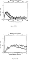
- Figure S26 is a comparison of INS spectra for bare NOTT-300 (Al), 0.25 H2/Al and 0.5 H2/Al loaded-NOTT-300 (Al).
- Figure S27 is a difference INS spectra plot for forward and back scattering between bare and 0.25H2/Al-loaded NOTT-300 (Al). The broad hump shows recoil of hydrogen; a very small and poorly defined peak at 10meV suggests a very weak interaction. A detailed view of the low energy transfers has been scaled up in Figure b.
- Figure S28 is a difference INS spectra plot for forward and back scattering between bare and 0.5 H2/Al-loaded NOTT-300 (Al). The broad hump shows recoil of hydrogen. The peak at 10meV is still broad and very weak, but can be seen to have increased in intensity slightly. Furthermore, an additional peak at ∼15 meV can be observed. This peak is very close to the rotational line of hydrogen (14.7 meV), further indicating that the interactions between the hydrogen and the NOTT-300 (Al) framework are very weak. A detailed view of the low energy transfers has been scaled up in Figure b.
- Figure S29 provides linear fitting of Van't Hoff plots for the CO2 adsorption isotherms at 0.5, 1.0, 1.5 and 2.0 mmol g-1 loadings;
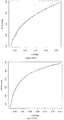
- Figure S30 provides linear virial fitting plots for the adsorption isotherms for (a) CO2 and (b) SO2 for NOTT-300(Al) at 273 K;
- Figure S31 provides non-linear virial fitting plots for the adsorption isotherms for (a) CO, (b) CH4, (c) O2, (d) N2 and (e) Ar for NOTT-300(Al) at 273 K;
- Figure S32 provides linear virial fitting plots for the adsorption isotherms for (a) CO2 and (b) SO2 for NOTT-300(Al) at 283 K;
- Figure S33 provides non-linear virial fitting plots for the adsorption isotherms for (a) CO, (b) CH4, (c) O2, (d) N2 and (e) Ar for NOTT-300(Al) at 283 K;
- Figure S34 provides linear virial fitting plots for the adsorption isotherms for (a) CO2 and (b) SO2 for NOTT-300(Al) at 293 K;
- Figure S35 provides non-linear virial fitting plots for the adsorption isotherms for (a) CO, (b) CH4, (c) O2, (d) N2 and (e) Ar for NOTT-300 at 293 K;
- Figure S36 provides linear virial fitting plots for the adsorption isotherms for (a) CO2 and (b) SO2 for NOTT-300(Al) at 303 K; and
- Figure S37 provides non-linear virial fitting plots for the adsorption isotherms for (a) CO, (b) CH4, (c) O2, (d) N2 and (e) Ar for NOTT-300(Al) at 303 K.
- For the purposes of this description the term "NOTT-300" is used to denote complexes M2(OH)2(C16O8H6) (M= Al, Cr, Sb, In, Ga, and Fe) whereas the term "NOTT-300-solvate" is used to denote the solvated form of the complex. The organic ligand C16O8H6 takes the form of biphenyl-3, 3',5,5' tetracarboxylate. Such structures are discussed in detail herein-below.
- Biphenyl-3,3',5,5'-tetracarboxylic acid (0.06 g, 0.182 mmol), Al(NO3)3·9H2O (0.34 g, 0.906 mmol), and piperazine (0.10 g, 1.26 mmol) were mixed and dispersed in a water (10.0 ml) and HNO3 (2.8M, 2.0 ml) was then added to the resulting white slurry. The slurry was transferred into a 23 ml autoclave which was sealed and heated to 210°C for 3 days. After cooling over 12 h to room temperature, the resulting white microcrystalline product was separated by filtration, washed with water and dried in air. Yield: 0.095 g (75%). Elemental analysis (% calc/found): Al2O16C16H20 (C 36.8/36.3, H 3.8/4.0, N 0.0/0.0). Selected IR: v/cm1: 3574(m), 3425(m), 2926(w), 1623(vs), 1570(vs), 1475(s), 1442(s), 1346(m), 1324(m), 1265(m), 1108(m), 1003(m), 914(w), 807(w), 742(m), 702(s), 668(m).
- Compared to traditional methods for the production of MOF materials, the synthetic conditions developed here for NOTT-300-(Al) can be viewed as constituting a green synthesis, not only because no organic solvent (e.g., DMF) is involved, but also because the ligand can be prepared from a simple oxidation reaction without using the toxic Pd(0) catalysts typically applied in Suzuki-coupling reactions to synthesise such polycarboxylate ligands.18,19 Thus, this synthesis offers potential for inexpensive, feasible and environmentally-friendly scale-up.
- The structure of NOTT-300 (Al)-solvate was solved from high resolution synchrotron PXRD data by ab initio methods in the chiral tetragonal
space group I4 122. NOTT-300 (Al)-solvate exhibits an open structure comprising chains of [AlO4(OH)2] moieties bridged by tetracarboxylate ligands L4-. The Al(III) ion in NOTT-300 (Al)-solvate is bound to six O-donors, four from carboxylates [Al-O = 1.935(1) and 1.929(2) Å] and two from bridging hydroxyl groups µ2-OP [Al-O = 1.930(1) Å]. Bond valence sum calculations give a valence of approximately 0.87 for this bridging oxygen atom, confirming its protonation to form a dangling µ2-OH group. This overall connectivity affords a porous 3D framework structure with 1D channels (Fig. 2 ) formed by corner-sharing [AlO4(OH)2] octahedra linked via two mutually cis-µ2-OH groups. Thus, the observed cis-configuration of µ2-OH groups is responsible for the observed chirality and rigidity of the framework in NOTT-300 (Al). The rigidity of the framework structure of NOTT-300 (Al) has been confirmed by in situ variable temperature (100-483 K) PXRD data (Fig. S16). Another important consequence of the cis-configuration is the formation of square-shaped channels with hydroxyl groups protruding into them, endowing the pore environment with free hydroxyl groups over four different directions (Fig. 2d ). The approximate diameter of the channel window, taking into account the van der Waals radii of the surface atoms, is ∼6.5 x 6.5 Å, and these channels are filled by crystallographically-disordered water molecules which are not bound to Al(III). The total free solvent (water) volume in NOTT-300 (Al)-solvate was estimated by PLATON/SOLV* to be 42% (*Spek, A. L. Structure validation in chemical crystallography. Acta Crystallogr., Sect. )). The water molecules can be readily removed by heating, giving the desolvated and activated material NOTT-300 (Al), the PXRD of which confirms retention of the original porous structure. Thermogravimetric analysis (TGA) confirms NOTT-300 (Al) to have high thermal stability with a decomposition temperature at 400 °C (Fig. S13). NOTT-300 (Al) also shows good chemical stability towards air, moisture and common organic solvents, and can be re-hydrated with retention of the framework structure (Fig. S14). Significantly, the framework porosity and surface area of NOTT-300 (Al) is retained upon multiple hydration-dehydration cycles (Fig. S25), thereby confirming the stability of this material to water. - Al-NOTT-300 (Al) exhibits highly selective uptake for CO2 and SO2 compared with CH4, CO, N2, H2, O2, and Ar. The CO2 selectivities, calculated from the ratio of initial slopes of the isotherm are 100, 86, 180, >105, 70, and 137 for CH4, CO, N2, H2, O2, and Ar, respectively. The SO2 selectivities, calculated from the ratio of the initial slopes of the isotherms are 3620, 3105, 6522, >105, 2518, and 4974 for CH4, CO, N2, H2, O2, and Ar, respectively. The thermodynamic parameters Qst and ΔS were calculated using the van't Hoff isochore on CO2 adsorption isotherms measured at 273-303 K. The Qst values lie in the range 27.5-28 kJ mol-1 for CO2 uptakes of 1-2 mmol g-1 and increase continuously thereafter to ∼30 kJ mol-1 at 4.5 mmol g-1. The error in Qst is estimated as 0.05-0.5 kJ mol-1 as shown by the error bars. Overall, ΔS decreases continuously with increasing surface coverage over the whole loading range. The error in ΔS is estimated as 0.2-1.6 J Kmol-1 as shown by the error bars.
- H2 and N2 isotherms at 77 K and the Ar isotherm at 87 K for NOTT-300 (Al) show, surprisingly, no apparent adsorption uptakes (Fig. S18). This is probably due to diffusion effects at low temperatures caused by the narrow pore channels. In contrast, low pressure CO2 isotherms at ambient temperatures (273-303 K) show very high uptake capacities, with a maximum value of 7.0 mmol g-1 at 273 K and 1.0 bar, representing one of the highest value observed for a MOF under these conditions (
Fig. 3a ).9 The CO2 uptake at 0.15 bar, which is relevant to the CO2 partial pressure in flue gas, is 2.64 mmol g-1 (Fig. S22). This uptake is higher than the value (0.682 mmol g-1 at 0.15 bar and 298 K) observed by other workers for H3[(Cu4Cl)3(BTTri)8]-en (H3BTTri = 1,3,5-tris(1H-1,2,3-triazol-5-yl)benzene),22 but lower than the value observed by other workers for Mg2(dobpdc)(mmen)1.6(H2O)0.4 (dobpdc4-=4,4'-dioxido-3,3'-biphenyldicarboxylate;mmen=N,N' dimethylethylenediamine) (3.14 mmol g-1 at 0.15 bar and 313 K). Analysis of the CO2 adsorption isotherm at 273 K by DFT/Monte-Carlo methods gives a surface area of 1370 m2 g-1, a pore size distribution centred at 5.7 Å, and a cumulative pore volume of 0.375 cm3 g-1 (Fig. S21), confirming the microporous nature of this material. Saturated CO2 uptake at 273 K and 7.0 bar was found to be 8.7 mmol g-1 (Fig. S20). These data are entirely consistent with the crystallographically-determined extra-framework pore volume of 0.433 cm3 g-1 and the channel window diameter of ∼6.5 Å. - Interestingly, compared with the isotherm for CO2, (kinetic diameter 3.30 Å), the isotherm for SO2 (kinetic diameter 4.11 Å) exhibits higher uptakes with a maximum capacity of 8.1 mmol g-1 at 273 K and 1.0 bar, representing the highest value observed in the current literature. The SO2 uptake increases sharply at low pressure (below 50 mbar) and reaches saturation at around 0.10 bar, giving a typical type-I isotherm. The very rapid uptake observed at low pressure indicates the presence of stronger interactions in NOTT-300 (Al)-SO2 compared with NOTT-300 (Al)-CO2. This is probably due to the high dipole moment of SO2 (1.62 D compared with 0 D for CO2) which results in stronger interactions of SO2 with the pore surface of NOTT-300 (Al). The density of adsorbed CO2 and SO2 in NOTT-300 (Al) is unknown. By using a density of 1.032 g cm-3 of liquid CO2 at 253 K or a density of 1.458 g cm-3 of liquid SO2 at its boiling point of 263 K, it can be deduced that the volumes of CO2 and SO2 adsorbed in NOTT-300 (Al) at 1.0 bar and 273 K are 0.298 and 0.356 cm3 g-1, respectively. This corresponds to fillings of 69% and 82%, respectively, of the total crystallographically-determined pore volume of 0.433 cm3 g-1. At 7.0 bar, up to 89% of the total pore volume in NOTT-300 (Al) is filled by CO2 molecules. These values are entirely reasonable considering that in each case the adsorption temperature lies above the relevant boiling point; moreover, in an isotherm experiment not all the void space within a porous material is necessarily accessible to the gaseous substrate. In contrast, under the same conditions the isotherms for CH4, CO, N2, H2, O2, and Ar show only surface adsorption by NOTT-300 (Al), with very low uptake of gas (0.04-0.25 mmol g-1). Significantly, comparison of the gas adsorption isotherms (
Fig. 3a ) clearly shows ultra-high selectivities for CO2 and SO2 (e.g., CO2/CH4 : 100; CO2/N2 : 180; CO2/H2 : >105; SO2/CH4 : 3620; SO2/N2 : 6522; SO2/H2 : >105), indicating the potential of NOTT-300 (Al) for the selective capture of these harmful gases. - Gas adsorption isotherms (CO2, SO2, CH4, N2, CO, O2, Ar, H2) for NOTT-300 (Al) have also been measured at more ambient temperatures (i.e., 283, 293 and 303 K), where highly selective uptakes for CO2 and SO2 are confirmed (Fig. S24), and the corresponding desorption isotherms exhibit full reversibility without hysteresis. This suggests that the adsorbed CO2 and SO2 gases can be readily released and that NOTT-300 (Al) can be re-generated at ambient temperatures without the need for heating, a factor which reduces the energy efficiency of traditional amine-based carbon capture systems.
- Direct visualisation of the interaction between CO2 molecules and the NOTT-300 (Al) host is crucial to understanding the detailed binding mechanism and hence the observed high selectivities. Inelastic neutron scattering (INS) is a powerful neutron spectroscopy technique which has been used widely to investigate the H2 binding interactions within various storage systems by exploiting the high neutron scattering cross-section of hydrogen (82.02 barns). However, this technique cannot directly detect the CO2 binding interaction within a carbon capture system because the scattering cross-sections for carbon (5.551 barns) and oxygen (4.232 barns) are too small to obtain a clear neutron scattering signal. In this study, INS and DFT been successfully combined to visualise captured CO2 molecules within NOTT-300 (Al) by investigating the change in the dynamics of the hydrogen atoms of the local MOF structure, including those of the hydroxyl groups and benzene rings of the ligand (
Fig. 4 ). Calculation of the INS spectra from DFT vibrational analysis can be readily achieved, and the DFT calculations relate directly to the INS spectra, and, in the case of solid state calculations, there are no approximations other than the use of DFT eigenvectors and eigenvalues to determine the spectral intensities.24 Comparison of INS spectra, measured at temperatures below 5 K to minimise the thermal motion of the adsorbed CO2 and the framework host, reveals two major increases in peak intensity on going from bare NOTT-300 (Al) to NOTT-300 (Al)·1.0CO2: peak I occurs at low energy transfer (30 meV) and peak II at high energy transfer (125 meV). Moreover, the peaks in the range 100-160 meV are slightly shifted to higher energies in NOTT-300 (Al)·1.0CO2 (Fig. 4b ), indicating a stiffening of the motion of the NOTT-300 (Al) host upon CO2 adsorption. To understand these changes, DFT calculations have been used to simulate the INS spectra and optimise the structures for NOTT-300 (Al) and NOTT-300 (Al)·1.0CO2. The INS spectra derived from these calculations show good agreement with experimental spectra and confirm that the adsorbed CO2 molecules interact end-on to the hydroxyl groups. The O···H distance between the CO2 molecule and the hydroxyl group is 2.335 Å, indicating a moderate-to-weak hydrogen bond (See Table S13 in the supplementary section of this specification). The optimised C-O bond distances in CO2 are 1.183 Å (hydrogen-bonded end) and 1.178 Å (free end), and the <OCO bond angle is 180°. Each adsorbed CO2 molecule is also surrounded by four aromatic C-H groups, forming weak cooperative supramolecular interactions between O(δ-) of CO2 and H(δ+) from -CH [O···H = 3.029, 3.190 Å, each occurring twice]. Specifically, peak I can be assigned to the O-H groups wagging perpendicular to the Al-O-Al direction, attributed to the presence of the CO2, and peak II to the wagging of the four aromatic C-H groups on four benzene rings adjacent to each CO2 molecule in conjunction with the wagging of the OH group along the Al-O-Al direction (Fig. 4d and film in SI). Thus, a total of five hydrogen atoms H(δ+) interact cooperatively with the O(δ-) charge centres of CO2 molecules in the channel via moderate-to-weak hydrogen bonds and supramolecular interactions. - The preferred binding sites for CO2 molecules within NOTT-300 (Al) have also been determined by in situ PXRD analysis which also confirms end-on binding of CO2 molecules to the hydroxyl group [O···H = 2.298(10) Å]. The weaker supramolecular contacts from surrounding C-H groups to the O(δ-) charged centres of CO2 molecules in the channel [O···H = 3.021(31), 3.171(22) Å, each occurring twice] are also observed. This PXRD analysis is in excellent agreement with the INS model obtained independently from DFT modelling with regard to both hydrogen-bonding and the combination of supramolecular binding interactions. Additionally, a second CO2(II) site has been identified in NOTT-300 (Al)·3.2CO2 studied by PXRD. This second site interacts principally with the first CO2 via dipole interaction [O(I)···C(II) = 3.920 Å], forming an edge-on intermolecular CO2 network [O(I)···(II) = 2.713(28) Å] along the pore channel that is reminiscent of solid CO2 (
Fig. 4c ). - In order to understand why low uptakes are observed for some gases while high selectivity for CO2 is achieved, the interactions between H2 and NOTT-300 (Al) were probed The INS spectra of NOTT-300 (Al)·1.0H2 show an overall increase in signal upon H2 loading, indicating adsorption of H2 by NOTT-300 (Al) at below 40 K (Fig. S26). The difference INS spectra, measured at below 5 K, between bare NOTT-300 (Al) and NOTT-300 (Al)·1.0H2 show a series of features that resemble the signal of liquid molecular H2. Significantly, the sharp rotational peak usually observed around 14.7 meV as a prominent feature in the INS of molecular H2 in the solid state or adsorbed on surface is not observed here. This suggests a 1D fluid-like recoil motion of the H2 along the channel25,26 consistent with extremely weak interactions and low uptake of H2 in NOTT-300 (Al) (Figs. S27, S28).
- In order to determine the reasons for the high selectivity and high uptake capacity, the preferred binding sites for SO2 molecules within NOTT-300 (Al) have been determined by in situ PXRD. The in situ PXRD confirms the retention of the structure of NOTT-300 (Al) upon inclusion and subsequent removal of SO2 (
Fig. 5a ), thereby confirming the high stability of NOTT-300 (Al) in the presence of corrosive SO2. Indeed, the uptake of SO2 in NOTT-300 (Al) is entirely reversible with no apparent loss of capacity on recycling. For NOTT-300 (Al)·4SO2 (at 1.0 bar), two distinct, equally-occupied binding sites (I and II) were located within the channel (Fig. 5b ): SO2(I) occupies the same position as CO2 and interacts with -OH groups via its O(δ-) charged centre [OSO···HOAl = 2.376(13) Å], which also forms weak interactions with four -CH groups from neighbouring benzene rings [OSO···HC = 2.806(14), 2.841(17), 3.111(16), 3.725(18) Å]. Thus, as for CO2, a total of five cooperative hydrogen bonds accommodate SO2(I) in a "pocket-like" cavity. A second site, identified as SO2(II), was observed between two SO2(I) molecules. However, no hydrogen bonding between the SO2(II) and -OH or -CH groups are apparent; rather, the O(δ-) centre of SO2(II) interacts with the S(δ+) charge centre of SO2(I), thus stabilising an SO2(I,II) intermolecular chain via O(δ-)···S(δ+) dipole interactions [O(I)···S(II) = 3.34(7) Å] (Fig. 5b ) within the channel. The S=O bond distances for SO2(I) and SO2(II) are 1.481(4) and 1.500(8) Å, respectively, with corresponding <O=S=O angles of 117.5(11) and 109.1(9)°. The structural investigation of NOTT-300 (Al)·4SO2 represents a distinct crystallographic study of a SO2-loaded MOF and gives important insights into the SO2 adsorption mechanism. - Despite the small total bound scattering cross section of sulphur (1.026 barns), comparison of the INS spectra below 5 K reveals two major increases in peak intensity on going from bare NOTT-300 (Al) to NOTT-300 (Al)·2SO2 (or NOTT-300 (Al)·3SO2): peak I occurs at low energy transfer (30-50 meV) and peak II at high energy transfer (125 meV), similar to that observed in the INS spectra for CO2-loaded NOTT-300 (Al) (
Fig. 6b ). Moreover, immediate stiffening of the motion of the NOTT-300 (Al) host was observed upon SO2 inclusion, as evidenced by the slight shift in INS peak to higher energies in NOTT-300 (Al)·2SO2 and NOTT-300 (Al)·3SO2 (Fig. 6a ). DFT simulation has also been performed to optimise the structures of both NOTT-300 (Al) and NOTT-300 (Al)·2SO2 materials. The simulated INS spectra show good agreement with the experimental spectra and are consistent with the adsorbed SO2 molecules interacting end-on to the hydroxyl groups via the hydrogen bond interactions [O···H = 2.338 Å] with additional supramolecular contacts with the adjacent aromatic C-H groups [O···H = 2.965-3.238 Å] (Fig. 6c ). The INS/DFT results are entirely consistent with the PXRD analysis and provide key insights into the dynamics of the NOTT-300 (Al) host upon SO2 inclusion. -
Table A Selectivity 273K 283K 293K 303K C2H2/C2H4 4.20 2.52 2.06 1.56 - High resolution powder diffraction data were collected on Beamline I11 at Diamond Light Source by using multi-analysing-crystal detectors (MACs)28 and an in-situ gas cell system. The powder pattern was firstly indexed on a body-centred tetragonal lattice and the independent unit cell parameters were refined using TOPAS.29 The body centring and the reflection condition 00l : l = 4n indicates that the space group is one of the
enantiomeric pair I4 122 andI 4 322. In the absence of any component capable of directing chirality, the product is expected to be a 1:1 racemic mixture. The structure solution was initially established inspace group I4 122 by charge flipping using the program Superflip,30 and further developed from subsequent difference Fourier analysis using TOPAS. The final structure refinement was carried out using the Rietveld method29 with isotropic displacement parameters for all atoms. A total of 40 disordered water molecules per unit cell were found within the pore channel and included in the final structure refinement for NOTT-300 (Al)-solvate. Upon desolvation and SO2 loading, we observe neither major changes to cell parameters nor extra features in the patterns, suggesting that there is no structural phase change during the experiment. However, upon SO2 loading, there are significant increases in the peak intensities at ∼6.2, 10.2, 12 and 14° 2θ, indicating that the SO2 molecules are adsorbed into the material, and that the overall microscopic ordering of the SO2/host system is increasing. A Monte-Carlo-based simulated annealing technique in which the guest SO2 molecules were treated as rigid bodies was used to locate their positions in NOTT-300 (Al)·4SO2. Two independent SO2 sites were found each with half occupancy. The SO2 content was refined giving a stoichiometry of 1.98(2) molecules of SO2 per Al, slightly higher than the experimental value of 1.7 SO2 per Al. The occupancy of the first CO2 site was determined to be 0.865(9) and the second CO2 site 0.727(7), leading to a total refined CO2 stoichiometry of 1.592(12) in excellent agreement with the experimental value of 1.6 CO2 per Al. The final stage of the Rietveld refinement involved soft restraints to the C-C bond lengths within the benzene rings. Rigid body refinement was applied to the CO2 and SO2 molecules in the pore. - [Al2(OH)2(C16H6O8)](H2O)6. White powder. Tetragonal,
space group I4 122, a = b = 14.82958(6), c = 11.77317(5) Å, V = 2589.11(3) Å3, M = 522.29, T = 293(2) K, Z = 4. The final Rietveld plot corresponds to satisfactory crystal structure model (R Bragg = 0.056) and profile (R p = 0.052 and R wp = 0.072) indicators with a goodness-of-fit parameter of 1.345. Final fractional coordinates for NOTT-300 (Al)-solvate are listed in Table S1.Table S1 Atomic positions for non-hydrogen atoms in NOTT-300 (Al)-solvate x y z Biso (Å2) Al1 0.69426(5) 0.30574(5) 0.5 0.72(13) O1 0.75744(13) 0.25 0.625 0.51(12) O2 0.89782(9) 0.28675(9) 0.99869(15) 0.51(12) O3 0.62165(10) 0.37371(10) 0.39436(12) 0.51(12) C1 0.59280(15) 0.36039(14) 0.69453(19) 0.70(13) C2 0.54498(10) 0.43181(7) 0.75722(10) 0.70(13) C3 0.5 0.5 0.69649(14) 0.70(13) C4 0.54071(10) 0.428618(71) 0.87716(8) 0.70(13) C5 0.5 0.5 0.93474(11) 0.70(13) O1w 0.91080(23) 0.80489(16) 0.94077(28) 21.6(2) O2w 0.45734(19) 0.73953(30) 0.06123(32) 11.9(3) O3w 0.13041(22) 0.29586(24) 0.53782(37) 35.7(3) - [Al2(OH)2(C16H6O8)](CO2)3.2. White powder. Tetragonal,
space group I4 122, a = b = 14.82432(6), c = 11.80570(5)Å, V = 2594.43(3) Å3, M = 550.03, T = 273(2) K, Z = 4. The final Rietveld plot corresponds to satisfactory crystal structure model (R Bragg = 0.025) and profile (R p = 0.043 and R wp = 0.059) indicators with a goodness-of-fit parameter of 1.531. Final fractional coordinates for NOTT-300 (Al)·3.2CO2 are listed in Table S2.Table S2 Atomic positions for NOTT-300 (Al)·3.2CO2 X y z Biso (Å2) Al1 0.30694(4) -0.30694(4) 0.5 0.93(40) O1 0.75117(13) 0.25 0.625 0.82(40) H1 0.8123(17) 0.25 0.625 0.75(40) O2 0.62152(22) 0.37975(22) 0.60276(28) 0.82(40) O3 0.60511(22) 0.28380(22) 0.75032(28) 0.82(40) C1 0.59215(19) 0.36044(15) 0.70222(15) 1.37(40) C2 0.54078(8) 0.43003(6) 0.76456(13) 1.37(40) C3 0.5 0.5 0.70584(14) 1.37(40) H3 0.5 0.5 0.6125(7) 1.37(40) C4 0.54078(8) 0.43003(6) 0.88199(13) 1.37(40) H4 0.5675(4) 0.3842(6) 0.9205(6) 1.37(40) C5 0.5 0.5 0.94071(14) 1.37(40) C1_1 1.0335(25) 0.25 0.6676(12) 15.1(2) O1_1 0.9673(23) 0.25 0.625 18.7(5) O2_1 1.0998(22) 0.25 0.7102(24) 39.4(8) C1_2 0.25 0.35535 0.375 18.3(2) O1_2 0.32821 0.35535 0.375 38.4(8) - [Al2(OH)2(C16H6O8)](SO2)4. White powder. Tetragonal,
space group I4 122, a = b = 14.84740(10), c = 11.80564(8)Å, V = 2602.50(4) Å3, M = 670.46, T = 273(2) K, Z = 4. The final Rietveld plot corresponds to satisfactory crystal structure model (R Bragg = 0.024) and profile (R p = 0.044 and R wp = 0.057) indicators with a goodness-of-fit parameter of 1.293. Final fractional coordinates for NOTT-300 (Al)·4SO2 are listed in Table S3.Table S3 Atomic positions for NOTT-300 (Al)·4SO2 X y z Biso (Å2) Al1 0.30668(4) -0.30668(4) 0.5 0.83(11) O1 0.75093(11) 0.25 0.625 0.50(11) H1 0.8094(7) 0.2737(13) 0.6182(19) 0.75(17) O2 0.87680(8) 0.12169(8) 0.10281(9) 0.50(11) O3 0.89634(7) 0.21365(7) 0.25360(13) 0.50(11) C1 0.85735(12) 0.09466(13) 0.79858(16) 0.90(12) C2 0.53958(11) 0.43084(7) 0.75958(9) 0.90(12) C3 0.5 0.5 0.69441(10) 0.90(12) H3 0.5 0.5 0.6125(7) 1.09(14) C4 0.54005(7) 0.42960(5) 0.87811(9) 0.90(12) H4 0.57318 0.38162 0.90735 1.09(14) C5 0.5 0.5 0.93693(9) 0.90(12) S1 0.062518 0.257889 -0.415951 15.1(2) O1s -0.036130 0.243180 -0.416293 5.8(2) O2s 0.110299 0.250886 -0.525706 39.4(8) S2 0.103150 0.184862 -0.037573 18.3(2) O3s 0.117697 0.239213 -0.143103 38.4(8) O4s 0.123069 0.242537 0.063692 24.4(4) - A detailed description has been given above for an aluminium hydroxyl metal organic framework complex. Analogues to this complex have also been synthesised based on indium, antimony, chromium and gallium. A metal organic framework has also be synthesised that contains both aluminium and iron functional groups. These analogue complexes also exhibit the same high uptake and selectivity for XO2 gases (X= C, S, O).
- A TEM image shows the crystals to have uniform morphology of ∼1 µm plates (Fig. S7a,b), and a high resolution (HRTEM) image confirms the presence of extended crystalline planes (Fig. S7c).
- To investigate the chemical stability of desolvated NOTT-300, an important feature for a capture material, PXRD patterns were collected for a range of NOTT-300 samples under variable chemical environments. Some of these are illustrated in Figure S14. After the collection of an original pattern for the as-synthesised sample, NOTT-300 solvate was degassed at 150 °C to generate desolvated NOTT-300. The desolvated material was then separated into ten portions, each of which was exposed to air for one month, or immersed in water, methanol, ethanol, CHCl3, CH3CN, DMF, THF, benzene or toluene for one week. Comparison of the resultant PXRD patterns confirms the excellent stability of the desolvated NOTT-300 material under air, water and common organic solvents. Figure S15 provides an illustration comparing of unit cell parameters of NOTT-300 under different chemical environments.
- To investigate the possible framework phase change of NOTT-300 (Al)-solvate as a function of temperature, variable temperature PXRD patterns were collected at 100-483 K for NOTT-300 (Al)-solvate (Fig. S16). Comparison of the PXRD patterns confirms that there is no framework phase transition over this temperature range and the framework of NOTT-300 (Al) remains intact after removal of the water molecules in the channels. The lattice parameters were refined via Le Bail methods, and results are summarised in Table S3. The overall change in the unit cell volume is less than 1.0 %, confirming the rigidity of the framework. Figure S16 provides variable temperature PXRD patterns for NOTT-300 (Al)-solvate (λ = 1.54056 Å). Figure S17. Unit cell parameters for NOTT-300 (Al)-solvate as a function of temperature.
Table S4 provides a summary of Le Bail refinement results and unit cell parameters for NOTT-300 (Al)-solvate. Table S4 a, b (Å) c (Å) V (Å3) Unit cell change (%) 100 K 14.78200(30) 11.76100(35) 2569.87(13) 0.000 140 K 14.78821(29) 11.76287(33) 2572.44(12) 0.100 180 K 14.79348(30) 11.76458(34) 2574.64(13) 0.186 220 K 14.80187(30) 11.76717(34) 2578.13(13) 0.321 260 K 14.81512(30) 11.77028(35) 2583.43(13) 0.527 273 K 14.82847(31) 11.77667(37) 2589.50(13) 0.764 303 K 14.83686(30) 11.77726(36) 2592.56(13) 0.883 333 K 14.83822(31) 11.77750(38) 2593.09(14) 0.904 363 K 14.83625(48) 11.78236(61) 2593.46(21) 0.918 383 K 14.83288(42) 11.78464(54) 2592.79(19) 0.892 403 K 14.82777(38) 11.78762(47) 2591.66(17) 0.848 423 K 14.81612(45) 11.81073(51) 2592.66(19) 0.887 443 K 14.81299(54) 11.81873(59) 2593.32(23) 0.912 463 K 14.81193(51) 11.82149(60) 2593.55(22) 0.921 483 K 14.8186(13) 11.8244(15) 2596.54(56) 1.04 - The NOTT-300 (Al)-solvate material was loaded into an IGA and degassed at 120 °C and 10-10 bar for 24 h to give the fully desolvated NOTT-300 (Al) material. A CO2 adsorption isotherm was then measured at 273 K and up to 1.0 bar (noted as first cycle). The desolvated sample was then exposed to high temperature (90-100 °C) water vapour for 1 h as a humidity treatment. The hydrated sample was then loaded into IGA and degassed again at 120 °C and 10-10 bar for 24 h to give desolvated NOTT-300 (Al) material. A second CO2 adsorption isotherm was then measured at 273 K and up to 1.0 bar (noted as the second cycle). The same humidity treatment (hydration), degassing (de-hydration), and CO2 adsorption were repeated twice more (noted as third and fourth cycles). Comparisons of these four CO2 adsorption isotherms confirm that there is no apparent loss of uptake capacity and that the pore surface can be fully regenerated, showing that the framework has good stability upon exposure to the above humidity cycle. Figure S25 illustrates the CO2 adsorption isotherms at 273 K for NOTT-300 (Al) upon cyclic hydration and desolvation process.
- The vibrational properties of the NOTT-300 (Al) were calculated using a combination of density functional theory (DFT) and plane-wave pseudopotential methods as implemented in the CASTEP code,2 using ultra-soft pseudopotentials with a plane-wave energy cutoff of 380 eV. Calculations were performed under the PBE approximation3 for exchange and correlation. The unit cell used has a volume of 2589.2 Å3 and contains 144 and 156 atoms for the bare and CO2-loaded materials, respectively. The wave functions were sampled according to the Monkhorst-Pack scheme with a k-points mesh of spacing ∼0.05 Å-1. The normal modes of the solid were determined from dynamical matrices calculated using finite displacements, by numerical differentiation. The INS spectra was the calculated using the aClimax software.4
- The calculation of the bare material is computationally stable, in the calculation of the vibrational frequencies, all the frequencies are positive. Figure S1 illustrates the potential energy surface along the first vibrational eigenvector of the hydrogen bond between CO2 and the -OH moieties. At the centre it is clear that the potential would give an unstable configuration from a classical point of view. The calculated solution of the Schrödinger equation gives the energy levels at 14.2 and 81 cm-1. The zero point energy is higher than the local maximum so that from a quantum point of view, the system is in a stable equilibrium. In the calculation of the MOF material loaded with four CO2 molecules per unit cell (Fig. S1), corresponding to NOTT-300 (Al)·1.0CO2, 8 imaginary frequency modes were found. Following the methodology previously used in MOF modelling,5 we calculated the potential energy surface (PES) along each of the negative frequency modes (corresponding to the rocking motion of the CO2 unit). Figure S1 shows the potential energy surface (PES) for the hydrogen bond between CO2 and -OH group of the NOTT-300 (Al)·1.0CO2. The obtained PES confirms that the zero-point energy (ZPE) level (the ground state) lies at an energy above the local minimum calculated by DFT. This means that these PES, although corresponding to an unstable structure from a static classical point of view, are indeed stable structures from the quantum mechanical view.
- The location of SO2 molecules in NOTT-300 has been optimised by DFT modelling based on the measured INS spectra. The DFT calculation was performed using the same settings as in the case of CO2. Notably, a high symmetry configuration, which does not take into account the disorder of SO2 molecules in the channel, was used.
- To estimate the isosteric enthalpies (ΔH) for CO2 adsorption, all isotherms at 273-303 K were fitted to the van't Hoff equation (1):

- Figure S29 provides linear fitting of Van't Hoff plots for the CO2 adsorption isotherms at 0.5, 1.0, 1.5 and 2.0 mmol g-1 loadings.
- To estimate the selectivity of CO2 and SO2 over other gases at zero surface coverage, all low pressure isotherm data at 273 K were fitted using a linear virial-type expression (2) employed previously to model gas sorption in MOFs. For the isotherms with overall low uptakes, where a good linear fitting cannot be obtained at low pressure, the non-linear virial type expression (3) was employed to achieve reasonable virial fitting with inclusion of data at relatively high pressure.6


- The Henry's constant (KH ) can be extracted from the values of the virial coefficients A 0 using expression (4).

- The Henry's Law selectivity for component i(CO2 or SO2) over other gas component j(CO, CH4, N2, O2, Ar or H2) was estimated based on the ratio of their Henry's constants (equation 5). The results are listed in Table S6. The selectivity data from virial fittings and Henry's Law analysis are confined to the zero surface coverage situations.

Table S5 provides virial fitting results and Henry's constants KH for CO2, SO2, CH4, N2, H2, O2 and Ar in NOTT-300 (Al) from isotherm data at 273 K. Table S5 CO2 SO2 CO CH4 N2 H2 O2 Ar A0 /ln(mol g-1 Pa-1 ) -14.11(8) 6.22(40) - 20.27(3) - 20.34(3) -20.81(1) n.a.* -20.04(2) -20.57(2) KH / mol g-1 Pa-1 7.45(57) x10-7 508(167) 1.57(5) x10-9 1.46(4) x10-9 9.14(10) x10-10 1.98(2) x10-9 1.16(2) x10-9 Fitting R2 0.990 0.996 >0.999 >0.999 >0.999 >0.999 >0.999 Residual error 0.00075 0.034 0.022 0.022 0.016 0.011 0.030 * The uptake of H2 isotherm at 273 K (below 0.01 wt%) is too low to obtain a reasonable virial fitting curve, and the Henry constant is therefore considered to be approximately zero. Table S6 provides virial fitting results and Henry's constants KH for CO2, SO2, CH4, N2, H2, O2 and Ar in NOTT-300 (Al) from isotherm data at 283 K. Table S6 CO2 SO2 CO CH4 N2 H2 O2 Ar A0 /ln(mol g-1 Pa-1 ) - 14.57(5) 5.75(50) - 20.38(2) - 20.29(2) - 20.84(1) n.a.* - 20.11(2) - 20.70(3) KH / mol g-1 Pa-1 4.70(24) x10-7 314(123) 1.41(3) x10-9 1.54(3) x10-9 8.88(9) x10-10 1.85(4) x10-9 1.03(4) x10-9 Fitting R2 0.994 0.991 >0.999 >0.999 >0.999 >0.999 >0.999 Residual error 0.00050 0.141 0.021 0.013 0.024 0.023 0.012 * The uptake of H2 isotherm at 283 K (below 0.01 wt%) is too low to obtain a reasonable virial fitting curve, and the Henry constant is therefore considered to be approximately zero. Table S7. Virial fitting results and Henry's constants KH for CO2, SO2, CH4, N2, H2, O2 and Ar in NOTT-300 (Al) from isotherm data at 293 K. Table S7 CO2 SO2 CO CH4 N2 H2 O2 Ar A0 /ln(mol g-1 Pa-1 ) - 15.52(3) 5.46(126) - 20.37(2) - 20.23(3) - 20.78(3) n.a.* - 19.98(2) - 20.69(2) KH / mol g-1 Pa-1 1.82(6) x10-7 235(168) 1.42(2) x10-9 1.63(4) x10-9 9.42(22) x10-10 2.10(5) x10-9 1.03(2) x10-9 Fitting R2 0.997 0.977 >0.999 >0.999 >0.999 >0.999 >0.999 Residual error 0.000030 0.024 0.020 0.013 0.011 0.017 0.015 * The uptake of H2 isotherm at 283 K (below 0.01 wt%) is too low to obtain a reasonable virial fitting curve, and the Henry constant is therefore considered to be approximately zero. Table S8 provides virial fitting results and Henry's constants KH for CO2, SO2, 5 CH4, N2, H2, O2 and Ar in NOTT-300 (Al) from isotherm data at 303 K. Table S8 CO2 SO2 CO CH4 N2 H2 O2 Ar A0 /ln(mol g-1 Pa-1) - 16.44(1) 4.30(100) - 20.27(2) - 20.15(2) -20.73(1) n.a.* - 20.01(1) - 20.42(2) KH / mol g-1 Pa-1 7.25(8) x10-8 73.7(465) 1.57(2) x10-9 1.77(4) x10-9 9.89(10) x10-10 2.04(1) x10-9 1.35(2) x10-9 Fitting R2 0.994 0.976 >0.999 >0.999 >0.999 >0.999 >0.999 Residual error 0.000072 0.050 0.016 0.016 0.0048 0.022 0.013 * The uptake of H2 isotherm at 283 K (below 0.01 wt%) is too low to obtain a reasonable virial fitting curve, and the Henry constant is therefore considered to be approximately zero. - Table S9 provides a summary of gas adsorption selectivity data obtained by two methods: (i)a the ratio of slopes of initial adsorption isotherm plot; (ii)b Henry's Law analysis at 273 K.
Table S9 Selectivity ratio Isotherm plot slop Henry's Law analysis CO2/CO 86 475 CO2/ CH 4100 510 CO2/ N 2180 815 CO2/H2 >105 >105 CO2/ O 270 376 CO2/Ar 137 642 SO2/CO 3105 >105 SO2/CH4 3620 >105 SO2/N2 6522 >105 SO2/H2 >105 >105 SO2/O2 2518 >105 SO2/Ar 4974 >105 a This method represents the selectivity at low pressure region (50-350 mbar) and is close to the situation from the direct comparison of gas uptakes. b This method represents the extreme selectivity at zero surface coverage of a given material, and therefore is higher than the values from method (i). Selectivity data obtained from method (i) are reported in the main text. - Table S10. Summary of gas adsorption selectivity data obtained by two methods: (i)a the ratio of slopes of initial adsorption isotherm plot; (ii)b Henry's Law analysis at 283 K.
Table S10 Selectivity ratio Isotherm plot slop Henry's Law analysis CO2/CO 67 333 CO2/CH4 57 305 CO2/N2 110 529 CO2/H2 >105 >105 CO2/ O 254 254 CO2/ Ar 90 456 SO2/CO 3586 >105 SO2/CH4 3061 >105 SO2/N2 5864 >105 SO2/H2 >105 >105 SO2/ O 22880 >105 SO2/Ar 4831 >105 a This method represents the selectivity at low pressure region (50-350 mbar) and is close to the situation from the direct comparison of gas uptakes. bThis method represents the extreme selectivity at zero surface coverage of a given material, and therefore is higher than the values from method (i). - Table S11. Summary of gas adsorption selectivity data obtained by two methods: (i)a the ratio of slopes of initial adsorption isotherm plot; (ii)b Henry's Law analysis at 293 K.
Table S11 Selectivity ratio Isotherm plot slop Henry's Law analysis CO2/ CO 45 128 CO2/ CH 439 112 CO2/N2 72 193 CO2/H2 >105 >105 CO2/ O 239 87 CO2/Ar 64 177 SO2/CO 2854 >105 SO2/CH4 2464 >105 SO2/N2 4545 >105 SO2/H2 >105 >105 SO2/O2 2490 >105 SO2/Ar 4070 >105 a This method represents the selectivity at low pressure region (50-350 mbar) and is close to the situation from the direct comparison of gas uptakes. bThis method represents the extreme selectivity at zero surface coverage of a given material, and therefore is higher than the values from method (i). - Table S12 provides a summary of gas adsorption selectivity data obtained by two methods: (i)a the ratio of slopes of initial adsorption isotherm plot; (ii)b Henry's Law analysis at 303 K.
Table S12 Selectivity ratio Isotherm plot slop Henry's Law analysis CO2/ CO 32 46 CO2/ CH 431 41 CO2/ N 246 73 CO2/H2 >105 >105 CO2/ O 230 36 CO2/Ar 41 54 SO2/CO 1586 >105 SO2/CH4 1510 >105 SO2/N2 2252 >105 SO2/H2 >105 >105 SO2/O2 1458 >105 SO2/Ar 2002 >105 a This method represents the selectivity at low pressure region (50-350 mbar) and is close to the situation from the direct comparison of gas uptakes. bThis method represents the extreme selectivity at zero surface coverage of a given material, and therefore is higher than the values from method (i). - A hydrogen bond system is conventionally represented as a linear A-H...B arrangement of a hydrogen donor (A-H) and an acceptor (B). Relevant properties of the different strengths of hydrogen bonds are given in Table C1. In this system, the hydrogen bond length H···O is around 2.3 Å (
Figure 4d ), and therefore it can be classed as a moderate-to-weak hydrogen bond. The four C-H supramolecular contacts are likely to be of lower energies. Based on this analysis, we view the observed value of Qst as entirely reasonable and consistent with the likely hydrogen bond energies. In addition, there is the possibility of electrostatic Al(III)/XO2 interactions. The high CO2 uptakes also reflect the relatively narrow pore size of the host which provides strong overlap potentials.Table S13 provides properties of strong, moderate and weak H-bonds. Properties Strong H-bonds Moderate H-bonds Weak H-bonds Bond energy (kJ mol-1 4-10 1-3 <1 Bond nature mostly covalent mostly electrostatic electrostatic Bond linearity, AH···B always linear mostly linear sometimes linear Bond length A-H (Å) 1.2 to 1.5 ca 1.0 ca 1.0 Bond length H··· B (Å) 1.2 to 1.5 1.5 to 2.2 2.2 to 3.2 Bond length A········B (Å) 2.2 to 2.5 2.5 to 3.2 3.2 to 4.0 - Biphenyl-3,3',5,5'-tetracarboxylic acid (0.015 g, 0.045 mmol), In(NO3)-(H2O)5 (0.014 mg, 0.045 mmol) and piperazine (7.0 mg, 0.081 mmol) were mixed and dispersed in DMF/MeCN mixture (1.3 mL, 1:0.3 v/v). The white slurry was acidified with dilute nitric acid (5 %, 0.3 mL) and heated to 100 °C. Upon reaching 60 °C the white slurry was observed to fully dissolve resulting in a colourless solution followed by precipitation of a white crystalline powder which was washed sequentially with DMF and dried briefly in air. Powder diffraction data (PXRD) confirm that the parent MOF NOTT-300 (In)-solv is iso-structural to NOTT-300(Al)-solv. Yield: 20 mg (75 %). Elemental analysis (% calc/found): [In2(C16H6O8)2·(DMF)0.75·(H2O)1.75 (C 33.02/33.02, H 2.20/2.53 N 1.58/1.58). Selected IR(ATR): v/cm-1 = 1705 (s), 1669 (s), 1652 (s), 1612 (m), 1549 (s), 1423 (s), 1367 (s), 1311 (w), 1253 (w), 1226 (w), 974 (m), 799 (s), 709 (s).
- Biphenyl-3,3',5,5'-tetracarboxylic acid (0.015 g, 0.045 mmol) and SbCl3 (0.010 mg, 0.045 mmol) were mixed and dispersed in DMF/MeCN mixture (1.3 mL, 1:0.3 v/v). The white slurry was acidified with dilute nitric acid (5 %, 0.3 mL) and heated to 100 °C. Upon reaching 60 °C the white slurry was observed to fully dissolve resulting in a colourless solution followed by precipitation of a white crystalline powder which was washed sequentially with DMF and dried briefly in air. [Sb2(C16H6O8)-2·(DMF) x ·(H2O) y . Colourless block (0.03 x 0.02 x 0.01 mm)
I4 122, a = 15.4500(5) c = 12.2908(6) Å, V = 2933.9(2) Å3, Z = 4, D calc = 1.362 g cm-3, µ = 14.927 mm-1, F(000) = 1136. A total of 1473 reflections was collected, of which 1392 were unique, with R int = 0.0606. Final R 1 (wR 2) = 0.0643 (0.2060) with GOF = 1.880. The final difference Fourier extrema were 3.32 and -0.88 e/Å3. - Chromium nitrate, Cr(NO3)3·9H2O, (0.36g, 0.9mmol) was dissolved in water (10mL), biphenyl-3,3',5,5'-tetracarboxylic acid (0.06g, 0.18mmol) was then added. Piperazine (0.1g) was added followed by addition of 2.8 M nitric acid (2 mL). The reaction mixture was transferred to a 2 mL autoclave which was sealed and heated to 210 °C for 72-96 h. The resulting powder product was separated by filtration and washed with water.
- NOTT-300(Ga2) {[Ga2(OH)2(C16H6O8)]} was synthesised under solvothermal conditions by reacting biphenyl-3,3',5,5'-tetracarboxylic acid (0.02 g, 0.06 mmol) and gallium nitrate, Ga(NO3)3 •xH2O, (0.1 g, 0.36 mmol), in a mixture of DMF, THF and water (8 mL, 2:5:1, v/v) which was then acidified with 5-15 drops of hydrochloric acid and heated at 75°C for 72 h.
- NOTT-301(Ga2)-solv crystallises in a chiral
space group I4 122 and shows a 3D open framework structure constructed from 1D helical [Ga(OH)2O4]∞ chains bridged by tetracarboxylate ligand. The Ga(III) ion is octahedrally coordinated via six O-donors: four from carboxylate groups and two from bridging hydroxyl groups µ2-OH which are aligned in cis confirmation.Table 1 Summary of unit cell parameters for (Ga2)-solvated, (Ga2)-desolvated and (Ga2)-CO2 loaded (In situ single crystal) Single Crystal Parameter cell (a=b), Å Parameter cell (c), Å Cell volume, Å3 M (Ga2)-solv 15.1675(9) 11.9197(15) 2742.2(4) 688.68 (Ga2) 15.0174(7) 11.9111(11) 2686.2(3) 499.66 CO2-loaded 15.0535 (6) 11.8737(10) 2690.7(3) 596.49 Table 2 Summary of unit cell parameters for (Ga2-xFex)MOF (x = 0, 0.13, 0.21, 0.45) Parameter cell (a=b), Å Parameter cell (c), Å Cell volume, Å3 RBragg Rp Rwp GOF Ga2 15.0071(1) 11.8814(9) 2675.9(4) 0.045 0.068 0.01 4.512 Ga1.87Fe0.13 15.0439(7) 11.8767(6) 2687.9(3) 0.036 0.068 0.090 2.673 Ga1.79Fe0.21 14.9980(1) 11.8938(1) 2675.4(5) 0.02 0.059 0.076 1.293 Ga1.55Fe0.45 15.0684(8) 11.9111(8) 2704.5(4) 0.06 0.050 0.066 1.877 - A mixed Ga-Fe material was obtained using a similar procedure but incorporating stoichiometric mixtures of gallium nitrate Ga(NO3)3•xH2O and iron nitrate Fe(NO3)3 •9H2O in the following ratios: [Ga1.87Fe0.13(OH)2(C16H6O8)]: (0.09g, 0.34mmol), (0.007g, 0.18mmol); [Ga1.79Fe0.21(OH)2(C16H6O8)]: (0.083g, 0.32mmol), (0.015g, 0.036mmol); [Ga1.55Fe0.45(OH)2(C16H6O8)]: (0.078g, 0.31mmol), (0.022g, 0.054mmol), respectively.
- In situ INS and PXRD studies on the non-amine-containing capture material NOTT-300 have led to the same conclusions, for all of the metal (III) complexes, namely that the M-OH groups (M= Al, Cr, Sb, In, Ga, Fe) in the pore cavity can participate in moderate interactions with XO2 (X= C, S, N) and C2Hx (x=2,4,6), and that these can be supplemented by cooperative interactions with adjacent C-H groups of benzene rings. The binding energy of these moderate-to-weak hydrogen bonds (Table S13) can be viewed as soft binding interactions, quite distinct from the direct bond formation between the N-centre of amine groups and the electro-positive C-carbon centre of CO2. The latter, seen in amine systems, lead to very high isosteric heats of adsorption (40-90 kJ mol-1 for physisorption; 85-105 kJ mol-1 for chemisorption) and result in a substantial energy penalty to release adsorbed CO2. The moderate isosteric heat of adsorption in NOTT-300 [eg 27-30 kJ mol-1 for NOTT-300-(Al) (
Fig. 3b )] confirms that the relatively weak hydrogen bonding interactions within this OH- decorated system are sufficiently strong to selectively bind CO2 and SO2. The weak interaction is also evidenced by the fully reversible desorption isotherms observed for these gases. This offers great promise not only for the efficient capture of CO2 SO2, and NO2 but also for their facile, low-energy and therefore economic release subsequently; moreover this "easy-on"/"easy-off' soft binding model is achieved without any reduction in either selectivity or capacity. -
Figure 27 illustrates a gas capture apparatus comprising acontainer 10 in which theMOF 40 is contained. Thecontainer 10 may have one ormore inlets 20 in which gases may enter thecontainer 10. The gases may be flue gases produced be a power station or from some other combustion or industrial processes for example in the production of iron, steel, ammonia and cement. In such applications theMOF 40 may be regenerated. In this case theMOF 40 incontainer 10 may be heated using aheater 80 so as drive-off adsorbed gases and regenerate theMOF 40 for its re-use. Alternatively desorption of gasses from theMOF 40 may proceed through the application of vacuum to the vessel containing the MOF. In such applications thecontainer 10 may be in fluid connection with avacuum pump 50 configured to draw off the gases (eg. XO2 (X= C, S, N) or hydrocarbons such as C2H2, C2H4, C2H6), that have been trapped and subsequently released by the MOF, for subsequent storage, handling and/or transportation, for example the gases may be compressed or liquefied before subsequent handling or transportation. Aninlet valve 60 may be closed and anoutlet valve 70 may be opened whilst theMOF 40 is being heated so that the captured are not released back into the flue. Or a vacuum may be applied throughvalve 70 to desorb the gas fromMOF 40 where heating is not used. Whilst the apparatus is being used to capture gases theinlet valve 60 will be open and theoutlet valve 60 may be closed. - The MOF may also be used as part of a cartridge system in which a cartridge 90 (or other container/ mechanism to support or hold the MOF) is placed in the gas stream to be processed. The
cartridge 90 may then be removed from the gas stream so as to be regenerated off-line from the gas stream.Figure 28(a) illustrates such acartridge 90 placed within a gas stream. Thecartridge 90 may cover the majority of the cross section of aconduit 100 carrying the gas stream or may be adapted to cover substantially all of the conduit cross section as illustrated inFigure 28(a) . When thecartridge 90 is in theconduit 100, theconduit 100 may form both theinlet 20 and the outlet 30 (as illustrated inFigure 28(a) ). Such a cartridge system may be useful for anaesthetic systems and exhausts systems from combustion.Figure 28(b) illustrates a cartridge at the end of a flue or exhaust pipe. In this case the side or sides of the cartridge distal from the flue may act as theoutlet 30. - All reagents were used as received from commercial suppliers without further purification. Analyses for C, H and N were carried out on a CE-440 elemental analyzer (EAI Company). Thermal gravimetric analyses (TGA) were performed under N2 flow (100 ml/min) with a heating rate of 2 °C/min using a TA SDT-600 thermogravimetric analyzer (TA Company). IR spectra were recorded using a Nicolet Avatar 360 FT-IR spectrophotometer. High-resolution transmission electron microscopy (TEM) imaging was performed using a Jeol 2100F transmission electron microscope using an accelerating voltage of 100 kV. TEM samples were prepared by casting several drops of a suspension of the NOTT-300 solvate complex in water onto copper-grid mounted lacy carbon film before drying under a stream of nitrogen. Variable temperature powder X-ray diffraction data (PXRD) were collected over the 2θ range 4-50° on a Bruker Advance D8 diffractometer using Cu-Kα1 radiation (λ = 1.54056 Å, 40 kV/40mA), and the temperature was controlled by an Oxford Cryosystems open-flow cryostat operating at 100-483 K.
- CO2, SO2, CH4, CO, N2, O2, H2 and Ar sorption isotherms were recorded at 77 K (liquid nitrogen), 87 K (liquid argon) or 273-303 K (temperature-programmed water bath from Hiden Company) on an IGA-003 system at the University of Nottingham under ultra-high vacuum from a diaphragm and turbo pumping system. All gases used were ultra-pure research grade (99.999%) purchased from BOC or AIRLIQUIDE. The density of the desolvated NOTT-300 sample used in buoyancy corrections was 1.80 g cm-3 and was estimated from the crystallographic density of the desolvated sample derived from the PLATON/SOLV1 results. In a typical gas adsorption experiment, ∼100 mg of NOTT-300 (Al)-solvate was loaded into the IGA, and degassed at 120 °C and high vacuum (10-10 bar) for 1 day to give fully desolvated NOTT-300 (Al).
- INS spectra were recorded on the TOSCA spectrometer at the ISIS Facility at the Rutherford Appleton Laboratory (UK) for energy transfers between ∼-2 and 500 meV. In this region TOSCA has a resolution of ∼1% ΔE/E. The desolvated NOTT-300 (Al) sample was loaded into a cylindrical vanadium sample container with an annealed copper vacuum seal and connected to a gas handling system. The sample was degassed at 10-7 mbar and 140 °C for 1 day to remove any remaining trace guest water molecules. The temperature during data collection was controlled using a helium cryostat (7 ± 0.2 K). The loading of CO2 was performed at room temperature in order to ensure that CO2 was present in the gas phase when not adsorbed and also to ensure sufficient mobility of CO2 inside the crystalline structure of NOTT-300 (Al). The loading of H2 was performed at 40-50 K in order ensure that H2 was adsorbed into NOTT-300 (Al). Subsequently, the temperature was reduced to below 10 K in order to perform the scattering measurements with the minimum achievable thermal motion for CO2 or H2. Background spectra (sample can plus NOTT-300 (Al)) were subtracted to obtain the difference spectra. INS was used to study the binding interaction and structure dynamics in this case, because it has several unique advantages:
- INS spectroscopy is ultra-sensitive to the vibrations of hydrogen atoms, and hydrogen is ten times more visible than other elements due to its high neutron cross-section.
- The technique is not subject to any optical selection rules. All vibrations are active and, in principle, measurable.
- INS observations are not restricted to the centre of the Brillouin zone (gamma point) as is the case for optical techniques.
- INS spectra can be readily and accurately modelled: the intensities are proportional to the concentration of elements in the sample and their cross-sections, and the measured INS intensities relate straightforwardly to the associated displacements of the scattering atom. Treatment of background correction is also straightforward.
- Neutrons penetrate deeply into materials and pass readily through the walls of metal containers making neutrons ideal to measure bulk properties of this material.
- INS spectrometers cover the whole range of the molecular vibrational spectrum, 0-500 meV (0-4000 cm-1)
- INS data can be collected at below 10 K, where the thermal motion of the MOF material and adsorbed CO2 molecules can be significantly reduced.
Claims (16)
- A metal organic framework comprising a metal (III) ion (M) and a biphenyl-3, 3',5,5' tetracarboxylate organic ligand, wherein more than one hydroxy ligand are present about the metal (III) ion, and wherein hydroxyl ligands point into the channels of the framework.
- The metal organic framework of claim 1 wherein the metal organic framework forms a three-dimensional framework incorporating corner sharing MO4(OH)2 octahedra.
- The metal organic framework of claim 1 or 2, wherein the metal (III) ion is one of Al(III), Cr(III), Sb(III), In(III), Ga(III), Co(III) and Fe(III).
- The metal organic framework of any one of claims 1, 2 or 3, wherein the metal (III) ion is:i) one of Al(III), Cr(III), In(III), Ga(III) and Fe(III); orii) one of Al(III), Cr(III), Ga(III) and Fe(III)
- The metal organic framework of any one of claims 1, 2 or 3, wherein the metal organic framework is a metal organic framework having the formula M2(OH)2(C16O8H6), where M = Al, In, Sb, Ga, Cr.
- The metal organic framework of any preceding claim, wherein the metal (III) ion is Al(III).
- A method for producing a metal-organic framework as claimed in any preceding claim, the method comprising the steps of:a. providing a metal salt;b. providing an organic ligand;c. mixing the metal salt and the organic ligand; andd. reacting the metal salt with organic ligand to form a metal-organic framework,wherein the metal salt is a metal (III) salt and wherein the organic ligand is biphenyl-3, 3',5,5' tetracarboxylic acid.
- The method of claim 7, wherein the metal (III) salt is:i) a metal (III) nitrate or a metal (III) chloride; orii) a metal (III) nitrate.
- The method of claim 7 or 8, wherein the metal of the metal salt is selected from Al(III), Cr(III), Sb(III), In(III), Ga(III), Co(III) and Fe(III).
- The method of claim 7, 8 or 9, wherein the metal of the metal salt is selected fromi) Al(III), Cr(III), In(III), Ga(III) and Fe(III); orii) Cr(III); oriii) Al(III).
- The method of any one of claims 7 to 10, wherein the metal organic framework is M2(OH)2(C16O8H6) and the method comprises reacting biphenyl-3,3',5,5'-tetracarboxylic acid with an M(III) salt selected from Al(III) nitrate, In(III) nitrate, Ga(III) nitrate, Cr(III) nitrate, Fe(III) nitrate, Co(III) nitrate, and Sb(III)Cl3.
- The method of claim 7, wherein the metal organic framework is (Ga2-x Fex)(OH)2(C16O8H8), x >0 , and the method comprises reacting a stoichiometric mixture of gallium nitrate, iron nitrate, hydrochloric acid and biphenyl-3,3',5,5'-tetracarboxylic acid under solvothermal conditions.
- The method of any one of claims 7 to 12, wherein the reaction of step d is conducted in water.
- Use of a metal organic framework as claimed in any one of claims 1 to 6 to capture one or more of CO2 and SO2 by the formation of a weak electrostatic interaction between the CO2 and/or SO2 molecule and the metal organic framework.
- Use of a metal organic framework as claimed in any one of claims 1 to 6 to capture NO2 by the formation of a weak electrostatic interaction between the NO2 molecule and the metal organic framework.
- Use of a metal organic framework as claimed in any one of claims 1 to 6 to capture a C2Hn (n = 2, 4, 6) molecule by the formation of a weak electrostatic interaction between the C2Hn molecule and the metal organic framework.
Applications Claiming Priority (2)
| Application Number | Priority Date | Filing Date | Title |
|---|---|---|---|
| GBGB1205365.8A GB201205365D0 (en) | 2012-03-27 | 2012-03-27 | Frameworks |
| PCT/GB2013/050811 WO2013144628A1 (en) | 2012-03-27 | 2013-03-27 | Metal -organic frameworks (mof) for gas capture |
Publications (2)
| Publication Number | Publication Date |
|---|---|
| EP2846896A1 EP2846896A1 (en) | 2015-03-18 |
| EP2846896B1 true EP2846896B1 (en) | 2019-04-24 |
Family
ID=46087192
Family Applications (1)
| Application Number | Title | Priority Date | Filing Date |
|---|---|---|---|
| EP13721988.7A Active EP2846896B1 (en) | 2012-03-27 | 2013-03-27 | Metal-organic frameworks (mof) for gas capture |
Country Status (4)
| Country | Link |
|---|---|
| US (1) | US9593132B2 (en) |
| EP (1) | EP2846896B1 (en) |
| GB (1) | GB201205365D0 (en) |
| WO (1) | WO2013144628A1 (en) |
Cited By (1)
| Publication number | Priority date | Publication date | Assignee | Title |
|---|---|---|---|---|
| CN113292736A (en) * | 2021-06-10 | 2021-08-24 | 北京工业大学 | Three-dimensional In metal-organic framework material, preparation method and application thereof |
Families Citing this family (44)
| Publication number | Priority date | Publication date | Assignee | Title |
|---|---|---|---|---|
| US10722863B2 (en) | 2011-10-18 | 2020-07-28 | The Regents Of The University Of California | Cooperative chemical adsorption of acid gases in functionalized metal-organic frameworks |
| WO2015164543A1 (en) * | 2014-04-22 | 2015-10-29 | The Regents Of The University Of California | Cooperative chemical adsorption of acid gases in functionalized metal-organic frameworks |
| EP2768608A4 (en) | 2011-10-18 | 2015-06-03 | Univ California | ORGANIC-INORGANIC MIXED STRUCTURES WITH ALKYLAMINE FUNCTION FOR SEPARATING COMPOSITE GASES |
| US11439944B2 (en) | 2012-08-10 | 2022-09-13 | University Of South Florida | Metal-organic materials for CO2 adsorption |
| GB201414113D0 (en) * | 2013-11-26 | 2014-09-24 | Texas A & M Univ Sys | Process for preparing metal organic framework materials |
| US9511348B2 (en) | 2014-01-07 | 2016-12-06 | University Of South Florida | Functionalized porous organic polymers for olefin/paraffin separations |
| EP3107638B1 (en) * | 2014-02-18 | 2023-07-05 | University Of South Florida | Metal-organic materials for c02 adsorption |
| WO2015171791A1 (en) | 2014-05-06 | 2015-11-12 | Massachusetts Institute Of Technology | Compositions and methods comprising conductive metal organic frameworks and uses thereof |
| EP3777997A1 (en) * | 2014-09-02 | 2021-02-17 | King Abdullah University Of Science And Technology | Trace and low concentration co2 removal methods and apparatus utlizing metal organic frameworks |
| CN104258814B (en) * | 2014-09-09 | 2016-06-29 | 西北大学 | One has CO2Metal-organic framework materials being selectively adsorbing and separating and preparation method thereof |
| CN104650125B (en) * | 2015-03-13 | 2017-10-13 | 辽宁大学 | One kind is based on InIIIMetal organic anion skeleton and its application |
| BR112018004265A2 (en) | 2015-09-14 | 2018-10-09 | Massachusetts Inst Technology | compositions and methods for selective olefin oligomerization comprising metal-organic structures |
| US10442875B2 (en) | 2015-09-14 | 2019-10-15 | Massachusetts Institute Of Technology | Compositions and methods for olefin polymerization comprising metal organic frameworks |
| CN105536574B (en) * | 2015-12-15 | 2019-12-03 | 中能科泰(北京)科技有限公司 | Filter membrane and its preparation method and application |
| US10413858B2 (en) * | 2015-12-28 | 2019-09-17 | Arizona Board Of Regents On Behalf Of Arizona State University | Metal-organic framework-based sorbents and methods of synthesis thereof |
| CN109414688A (en) | 2016-05-27 | 2019-03-01 | 麻省理工学院 | The composition and correlation technique comprising metal organic framework absorbed for compound |
| CN106064087B (en) * | 2016-06-08 | 2018-08-17 | 南京工业大学 | Method for preparing VOCs catalytic combustion catalyst |
| JP6972102B2 (en) | 2016-08-10 | 2021-11-24 | リサーチ トライアングル インスティテュート | Solid-phase crystallization method of metal-organic framework in mesoporous material and its hybrid material |
| US10266272B2 (en) | 2016-08-16 | 2019-04-23 | Hamilton Sundstrand Corporation | Catalytic ozone removal |
| US11179708B2 (en) | 2016-10-04 | 2021-11-23 | Massachusetts Institute Of Technology | Compositions and methods for selective carbonylation of heterocyclic compounds |
| WO2019010517A1 (en) * | 2017-07-13 | 2019-01-17 | The University Of Melbourne | Methods of capturing and storing anaesthetics using metal organic frameworks |
| KR102148513B1 (en) | 2017-09-28 | 2020-08-26 | 주식회사 엘지화학 | A carbon -surfur complex, manufacturing method thereof and lithium secondary battery comprising the same |
| US11857910B2 (en) * | 2018-06-11 | 2024-01-02 | King Abdullah University Of Science And Technology | Metal-organic frameworks for sorption and sensing applications |
| WO2019241281A1 (en) * | 2018-06-11 | 2019-12-19 | Ohio State Innovation Foundation | Metal-organic frameworks containing metal-hydroxide moieties and methods of making and using thereof |
| CN111151145B (en) * | 2018-11-08 | 2022-04-05 | 中国石油化工股份有限公司 | Super-hydrophobic separation membrane and preparation method and application thereof |
| US20200171482A1 (en) | 2018-11-30 | 2020-06-04 | International Business Machines Corporation | Moisture and volatile organic compound content measuring |
| CN111375274B (en) * | 2018-12-31 | 2022-10-11 | 中国石油化工股份有限公司 | Containing SO 2 Gas treatment method and apparatus |
| CN110038517B (en) * | 2019-03-21 | 2022-03-15 | 中山大学 | UiO-66-based metal organic framework material for indoor formaldehyde purification and application thereof |
| WO2020214814A1 (en) * | 2019-04-18 | 2020-10-22 | Massachusetts Institute Of Technology | Compositions and methods for carbon dioxide sensing |
| CN110180501B (en) * | 2019-05-09 | 2022-02-18 | 南京理工大学 | Magnetic-based metal-organic nano core-shell material with adjustable diameter and preparation method thereof |
| CN112029104B (en) * | 2019-06-03 | 2021-05-25 | 中国科学院大连化学物理研究所 | Preparation of metal-organic framework film by vapor-assisted epitaxial growth method and its application |
| CN110253970B (en) * | 2019-06-27 | 2021-01-19 | 福建船政交通职业学院 | Iron-indium annular composite microcrystalline magnetic disk |
| CN110253980B (en) * | 2019-06-27 | 2021-04-06 | 福建船政交通职业学院 | Method for manufacturing iron-indium annular composite microcrystal magnetic disk |
| CN111318126A (en) * | 2020-02-19 | 2020-06-23 | 浙江大学衢州研究院 | A kind of method for removing sulfuric acid gas |
| JP7633229B2 (en) * | 2020-02-27 | 2025-02-19 | 学校法人立教学院 | Metal-organic frameworks using terphenyl-based carboxylate ions as ligands |
| CN111499879A (en) | 2020-04-24 | 2020-08-07 | 苏州大学 | Use of ionizing radiation sources for the production of porous crystalline materials |
| US11493180B2 (en) | 2020-07-08 | 2022-11-08 | Abdullah Alrasheed | Cleansing lamp utilizing metal-organic framework |
| CN114130177B (en) * | 2020-09-03 | 2022-11-15 | 中国科学院大连化学物理研究所 | Tetrahydrofuran gas trapping method for generating and decomposing by using hydrate |
| CN112225904B (en) * | 2020-11-09 | 2022-06-10 | 西安工程大学 | Metal-organic framework materials based on V-type carboxylic acid ligands and preparation methods and applications |
| CN112812320A (en) * | 2021-03-08 | 2021-05-18 | 沈阳大学 | Preparation of nitrogen-substituted metal organic framework material and high-pressure methane storage application thereof |
| CN113354828A (en) * | 2021-05-08 | 2021-09-07 | 沈阳大学 | Preparation and application of novel stable metal organic framework material |
| WO2023044364A1 (en) | 2021-09-15 | 2023-03-23 | Enko Chem, Inc. | Protoporphyrinogen oxidase inhibitors |
| CN116693877B (en) * | 2023-07-04 | 2025-09-23 | 南开大学 | A three-dimensional indium organic framework compound and its synthesis method and application in fluorescence identification of sophocarpine |
| CN117736724B (en) * | 2023-12-04 | 2025-11-14 | 浙江大学 | Bifunctional fluorescent probes and methods for simultaneous detection of hydroxyl radicals and iron ions |
Family Cites Families (7)
| Publication number | Priority date | Publication date | Assignee | Title |
|---|---|---|---|---|
| US7799120B2 (en) | 2005-09-26 | 2010-09-21 | The Regents Of The University Of Michigan | Metal-organic frameworks with exceptionally high capacity for storage of carbon dioxide at room-temperature |
| US7556673B2 (en) | 2006-11-24 | 2009-07-07 | Basf Aktiengesellschaft | Method for the separation of carbon dioxide using a porous metal-organic framework material |
| WO2008129051A2 (en) | 2007-04-24 | 2008-10-30 | Basf Se | Organometallic framework materials having a hexagonal-trigonal structure based on aluminum, iron, and chromium, and a dicarboxylic acid |
| FR2927911A1 (en) * | 2008-02-27 | 2009-08-28 | Inst Francais Du Petrole | NEW IM-19 ORGANIC-INORGANIC HYBRID MATERIAL AND PROCESS FOR PREPARATION THEREOF |
| EP2437867A4 (en) | 2009-06-19 | 2012-12-05 | Univ California | CARBON DIOXIDE DETECTION AND STORAGE WITH OPEN FRAMEWORK |
| FR2951725B1 (en) * | 2009-10-23 | 2011-10-28 | Inst Francais Du Petrole | NOVEL MIL-53-AI-N3 ORGANIC-INORGANIC HYBRID SOLID WITH AZO-FUNCTION AND PROCESS FOR PREPARING THE SAME |
| GB201017095D0 (en) * | 2010-10-11 | 2010-11-24 | Univ St Andrews | Novel large pore MOFs |
-
2012
- 2012-03-27 GB GBGB1205365.8A patent/GB201205365D0/en not_active Ceased
-
2013
- 2013-03-27 WO PCT/GB2013/050811 patent/WO2013144628A1/en not_active Ceased
- 2013-03-27 EP EP13721988.7A patent/EP2846896B1/en active Active
- 2013-03-27 US US14/388,466 patent/US9593132B2/en active Active
Non-Patent Citations (2)
| Title |
|---|
| FINSY V ET AL: "Separation of CO"2/CH"4 mixtures with the MIL-53(Al) metal-organic framework", MICROPOROUS AND MESOPOROUS MATERIALS, ELSEVIER, AMSTERDAM, NL, vol. 120, no. 3, 15 April 2009 (2009-04-15), pages 221 - 227, XP025995549, ISSN: 1387-1811, [retrieved on 20090227], DOI: 10.1016/J.MICROMESO.2008.11.007 * |
| MATTHIAS MENDT ET AL: "Structural Phase Transitions and Thermal Hysteresis in the Metal Organic Framework Compound MIL-53 As Studied by Electron Spin Resonance Spectroscopy", J. PHYS. CHEM. C,, vol. 114, no. 45, 18 November 2010 (2010-11-18), pages 19443 - 19451, XP002698449, DOI: 10.1021/JP107487G * |
Cited By (1)
| Publication number | Priority date | Publication date | Assignee | Title |
|---|---|---|---|---|
| CN113292736A (en) * | 2021-06-10 | 2021-08-24 | 北京工业大学 | Three-dimensional In metal-organic framework material, preparation method and application thereof |
Also Published As
| Publication number | Publication date |
|---|---|
| US9593132B2 (en) | 2017-03-14 |
| WO2013144628A1 (en) | 2013-10-03 |
| GB201205365D0 (en) | 2012-05-09 |
| US20150047505A1 (en) | 2015-02-19 |
| EP2846896A1 (en) | 2015-03-18 |
Similar Documents
| Publication | Publication Date | Title |
|---|---|---|
| US9593132B2 (en) | Metal-organic frameworks (MOF) for gas capture | |
| Forster et al. | Hydrogen adsorption in nanoporous nickel (II) phosphates | |
| US10821417B2 (en) | Zeolitic imidazolate frameworks | |
| Yang et al. | Selectivity and direct visualization of carbon dioxide and sulfur dioxide in a decorated porous host | |
| Sumida et al. | Carbon dioxide capture in metal–organic frameworks | |
| US8227375B2 (en) | Gas adsorption on metal-organic frameworks | |
| US11058985B2 (en) | Methods for gas separation | |
| US9138719B1 (en) | Metal-organic materials (MOMs) for CO2 adsorption and methods of using MOMs | |
| US11318409B2 (en) | Ultramicro to mesopore frameworks for selective separation and storage of noble gases | |
| US9127025B2 (en) | Zn5(BTA)6(TDA)2—a robust highly interpenetrated metal-organic framework constructed from pentanuclear clusters for selective sorption of gas molecules | |
| US9604195B2 (en) | Metal-organic materials (MOMs) for CO2 adsorption and methods of using MOMs | |
| Lee et al. | Highly efficient bromine capture and storage using N-containing porous organic cages | |
| US9504986B2 (en) | Metal-organic materials (MOMS) for polarizable gas adsorption and methods of using MOMS | |
| WO2014074679A1 (en) | Metal-organic materials (moms) for polarizable gas adsorption and methods of using moms | |
| Pandey et al. | Revisiting Competitive Adsorption of Small Molecules in the Metal–Organic Framework Ni-MOF-74 | |
| EP4471319A2 (en) | Multifunctional co-ordination framework materials | |
| US20170113204A1 (en) | Metal-organic materials for c02 adsorption | |
| US20230294033A1 (en) | Ultramicro to mesopore frameworks for selective separation and storage of noble gases | |
| EP3107638B1 (en) | Metal-organic materials for c02 adsorption | |
| Xue et al. | Efficient C2H2/CO2 separation in anion-functionalized metal–organic framework with high C2H2 packing density | |
| US11439944B2 (en) | Metal-organic materials for CO2 adsorption | |
| Applegate | Structure-function relationships and design principles of metal-organic nanotubular materials | |
| Assen | Mixed-metal approach towards assembling highly stable metal organic framework based adsorbent for simultaneous capture of CO2 and H2S | |
| Robles | Cyclobenzoins for Energy Industries | |
| Asgari | Characterization of metal organic frameworks of interest for gas adsorption/separation applications |
Legal Events
| Date | Code | Title | Description |
|---|---|---|---|
| PUAI | Public reference made under article 153(3) epc to a published international application that has entered the european phase |
Free format text: ORIGINAL CODE: 0009012 |
|
| 17P | Request for examination filed |
Effective date: 20141025 |
|
| AK | Designated contracting states |
Kind code of ref document: A1 Designated state(s): AL AT BE BG CH CY CZ DE DK EE ES FI FR GB GR HR HU IE IS IT LI LT LU LV MC MK MT NL NO PL PT RO RS SE SI SK SM TR |
|
| AX | Request for extension of the european patent |
Extension state: BA ME |
|
| DAX | Request for extension of the european patent (deleted) | ||
| STAA | Information on the status of an ep patent application or granted ep patent |
Free format text: STATUS: EXAMINATION IS IN PROGRESS |
|
| 17Q | First examination report despatched |
Effective date: 20161208 |
|
| GRAP | Despatch of communication of intention to grant a patent |
Free format text: ORIGINAL CODE: EPIDOSNIGR1 |
|
| STAA | Information on the status of an ep patent application or granted ep patent |
Free format text: STATUS: GRANT OF PATENT IS INTENDED |
|
| INTG | Intention to grant announced |
Effective date: 20180627 |
|
| RAP1 | Party data changed (applicant data changed or rights of an application transferred) |
Owner name: THE UNIVERSITY OF NOTTINGHAM |
|
| GRAS | Grant fee paid |
Free format text: ORIGINAL CODE: EPIDOSNIGR3 |
|
| RAP1 | Party data changed (applicant data changed or rights of an application transferred) |
Owner name: THE UNIVERSITY OF MANCHESTER |
|
| GRAA | (expected) grant |
Free format text: ORIGINAL CODE: 0009210 |
|
| STAA | Information on the status of an ep patent application or granted ep patent |
Free format text: STATUS: THE PATENT HAS BEEN GRANTED |
|
| AK | Designated contracting states |
Kind code of ref document: B1 Designated state(s): AL AT BE BG CH CY CZ DE DK EE ES FI FR GB GR HR HU IE IS IT LI LT LU LV MC MK MT NL NO PL PT RO RS SE SI SK SM TR |
|
| REG | Reference to a national code |
Ref country code: GB Ref legal event code: FG4D |
|
| REG | Reference to a national code |
Ref country code: CH Ref legal event code: EP |
|
| REG | Reference to a national code |
Ref country code: AT Ref legal event code: REF Ref document number: 1123448 Country of ref document: AT Kind code of ref document: T Effective date: 20190515 Ref country code: IE Ref legal event code: FG4D |
|
| REG | Reference to a national code |
Ref country code: DE Ref legal event code: R096 Ref document number: 602013054286 Country of ref document: DE |
|
| REG | Reference to a national code |
Ref country code: NL Ref legal event code: MP Effective date: 20190424 |
|
| REG | Reference to a national code |
Ref country code: LT Ref legal event code: MG4D |
|
| PG25 | Lapsed in a contracting state [announced via postgrant information from national office to epo] |
Ref country code: NL Free format text: LAPSE BECAUSE OF FAILURE TO SUBMIT A TRANSLATION OF THE DESCRIPTION OR TO PAY THE FEE WITHIN THE PRESCRIBED TIME-LIMIT Effective date: 20190424 |
|
| PG25 | Lapsed in a contracting state [announced via postgrant information from national office to epo] |
Ref country code: SE Free format text: LAPSE BECAUSE OF FAILURE TO SUBMIT A TRANSLATION OF THE DESCRIPTION OR TO PAY THE FEE WITHIN THE PRESCRIBED TIME-LIMIT Effective date: 20190424 Ref country code: NO Free format text: LAPSE BECAUSE OF FAILURE TO SUBMIT A TRANSLATION OF THE DESCRIPTION OR TO PAY THE FEE WITHIN THE PRESCRIBED TIME-LIMIT Effective date: 20190724 Ref country code: PT Free format text: LAPSE BECAUSE OF FAILURE TO SUBMIT A TRANSLATION OF THE DESCRIPTION OR TO PAY THE FEE WITHIN THE PRESCRIBED TIME-LIMIT Effective date: 20190824 Ref country code: AL Free format text: LAPSE BECAUSE OF FAILURE TO SUBMIT A TRANSLATION OF THE DESCRIPTION OR TO PAY THE FEE WITHIN THE PRESCRIBED TIME-LIMIT Effective date: 20190424 Ref country code: FI Free format text: LAPSE BECAUSE OF FAILURE TO SUBMIT A TRANSLATION OF THE DESCRIPTION OR TO PAY THE FEE WITHIN THE PRESCRIBED TIME-LIMIT Effective date: 20190424 Ref country code: LT Free format text: LAPSE BECAUSE OF FAILURE TO SUBMIT A TRANSLATION OF THE DESCRIPTION OR TO PAY THE FEE WITHIN THE PRESCRIBED TIME-LIMIT Effective date: 20190424 Ref country code: HR Free format text: LAPSE BECAUSE OF FAILURE TO SUBMIT A TRANSLATION OF THE DESCRIPTION OR TO PAY THE FEE WITHIN THE PRESCRIBED TIME-LIMIT Effective date: 20190424 Ref country code: ES Free format text: LAPSE BECAUSE OF FAILURE TO SUBMIT A TRANSLATION OF THE DESCRIPTION OR TO PAY THE FEE WITHIN THE PRESCRIBED TIME-LIMIT Effective date: 20190424 |
|
| PG25 | Lapsed in a contracting state [announced via postgrant information from national office to epo] |
Ref country code: LV Free format text: LAPSE BECAUSE OF FAILURE TO SUBMIT A TRANSLATION OF THE DESCRIPTION OR TO PAY THE FEE WITHIN THE PRESCRIBED TIME-LIMIT Effective date: 20190424 Ref country code: RS Free format text: LAPSE BECAUSE OF FAILURE TO SUBMIT A TRANSLATION OF THE DESCRIPTION OR TO PAY THE FEE WITHIN THE PRESCRIBED TIME-LIMIT Effective date: 20190424 Ref country code: BG Free format text: LAPSE BECAUSE OF FAILURE TO SUBMIT A TRANSLATION OF THE DESCRIPTION OR TO PAY THE FEE WITHIN THE PRESCRIBED TIME-LIMIT Effective date: 20190724 Ref country code: PL Free format text: LAPSE BECAUSE OF FAILURE TO SUBMIT A TRANSLATION OF THE DESCRIPTION OR TO PAY THE FEE WITHIN THE PRESCRIBED TIME-LIMIT Effective date: 20190424 Ref country code: GR Free format text: LAPSE BECAUSE OF FAILURE TO SUBMIT A TRANSLATION OF THE DESCRIPTION OR TO PAY THE FEE WITHIN THE PRESCRIBED TIME-LIMIT Effective date: 20190725 |
|
| REG | Reference to a national code |
Ref country code: AT Ref legal event code: MK05 Ref document number: 1123448 Country of ref document: AT Kind code of ref document: T Effective date: 20190424 |
|
| PG25 | Lapsed in a contracting state [announced via postgrant information from national office to epo] |
Ref country code: IS Free format text: LAPSE BECAUSE OF FAILURE TO SUBMIT A TRANSLATION OF THE DESCRIPTION OR TO PAY THE FEE WITHIN THE PRESCRIBED TIME-LIMIT Effective date: 20190824 |
|
| REG | Reference to a national code |
Ref country code: DE Ref legal event code: R097 Ref document number: 602013054286 Country of ref document: DE |
|
| PG25 | Lapsed in a contracting state [announced via postgrant information from national office to epo] |
Ref country code: AT Free format text: LAPSE BECAUSE OF FAILURE TO SUBMIT A TRANSLATION OF THE DESCRIPTION OR TO PAY THE FEE WITHIN THE PRESCRIBED TIME-LIMIT Effective date: 20190424 Ref country code: DK Free format text: LAPSE BECAUSE OF FAILURE TO SUBMIT A TRANSLATION OF THE DESCRIPTION OR TO PAY THE FEE WITHIN THE PRESCRIBED TIME-LIMIT Effective date: 20190424 Ref country code: EE Free format text: LAPSE BECAUSE OF FAILURE TO SUBMIT A TRANSLATION OF THE DESCRIPTION OR TO PAY THE FEE WITHIN THE PRESCRIBED TIME-LIMIT Effective date: 20190424 Ref country code: SK Free format text: LAPSE BECAUSE OF FAILURE TO SUBMIT A TRANSLATION OF THE DESCRIPTION OR TO PAY THE FEE WITHIN THE PRESCRIBED TIME-LIMIT Effective date: 20190424 Ref country code: RO Free format text: LAPSE BECAUSE OF FAILURE TO SUBMIT A TRANSLATION OF THE DESCRIPTION OR TO PAY THE FEE WITHIN THE PRESCRIBED TIME-LIMIT Effective date: 20190424 Ref country code: CZ Free format text: LAPSE BECAUSE OF FAILURE TO SUBMIT A TRANSLATION OF THE DESCRIPTION OR TO PAY THE FEE WITHIN THE PRESCRIBED TIME-LIMIT Effective date: 20190424 |
|
| PG25 | Lapsed in a contracting state [announced via postgrant information from national office to epo] |
Ref country code: IT Free format text: LAPSE BECAUSE OF FAILURE TO SUBMIT A TRANSLATION OF THE DESCRIPTION OR TO PAY THE FEE WITHIN THE PRESCRIBED TIME-LIMIT Effective date: 20190424 Ref country code: SM Free format text: LAPSE BECAUSE OF FAILURE TO SUBMIT A TRANSLATION OF THE DESCRIPTION OR TO PAY THE FEE WITHIN THE PRESCRIBED TIME-LIMIT Effective date: 20190424 |
|
| PLBE | No opposition filed within time limit |
Free format text: ORIGINAL CODE: 0009261 |
|
| STAA | Information on the status of an ep patent application or granted ep patent |
Free format text: STATUS: NO OPPOSITION FILED WITHIN TIME LIMIT |
|
| PG25 | Lapsed in a contracting state [announced via postgrant information from national office to epo] |
Ref country code: TR Free format text: LAPSE BECAUSE OF FAILURE TO SUBMIT A TRANSLATION OF THE DESCRIPTION OR TO PAY THE FEE WITHIN THE PRESCRIBED TIME-LIMIT Effective date: 20190424 |
|
| 26N | No opposition filed |
Effective date: 20200127 |
|
| PG25 | Lapsed in a contracting state [announced via postgrant information from national office to epo] |
Ref country code: SI Free format text: LAPSE BECAUSE OF FAILURE TO SUBMIT A TRANSLATION OF THE DESCRIPTION OR TO PAY THE FEE WITHIN THE PRESCRIBED TIME-LIMIT Effective date: 20190424 |
|
| PG25 | Lapsed in a contracting state [announced via postgrant information from national office to epo] |
Ref country code: MC Free format text: LAPSE BECAUSE OF FAILURE TO SUBMIT A TRANSLATION OF THE DESCRIPTION OR TO PAY THE FEE WITHIN THE PRESCRIBED TIME-LIMIT Effective date: 20190424 |
|
| REG | Reference to a national code |
Ref country code: CH Ref legal event code: PL |
|
| REG | Reference to a national code |
Ref country code: BE Ref legal event code: MM Effective date: 20200331 |
|
| PG25 | Lapsed in a contracting state [announced via postgrant information from national office to epo] |
Ref country code: LU Free format text: LAPSE BECAUSE OF NON-PAYMENT OF DUE FEES Effective date: 20200327 |
|
| PG25 | Lapsed in a contracting state [announced via postgrant information from national office to epo] |
Ref country code: CH Free format text: LAPSE BECAUSE OF NON-PAYMENT OF DUE FEES Effective date: 20200331 Ref country code: IE Free format text: LAPSE BECAUSE OF NON-PAYMENT OF DUE FEES Effective date: 20200327 Ref country code: LI Free format text: LAPSE BECAUSE OF NON-PAYMENT OF DUE FEES Effective date: 20200331 |
|
| PG25 | Lapsed in a contracting state [announced via postgrant information from national office to epo] |
Ref country code: BE Free format text: LAPSE BECAUSE OF NON-PAYMENT OF DUE FEES Effective date: 20200331 |
|
| PG25 | Lapsed in a contracting state [announced via postgrant information from national office to epo] |
Ref country code: MT Free format text: LAPSE BECAUSE OF FAILURE TO SUBMIT A TRANSLATION OF THE DESCRIPTION OR TO PAY THE FEE WITHIN THE PRESCRIBED TIME-LIMIT Effective date: 20190424 Ref country code: CY Free format text: LAPSE BECAUSE OF FAILURE TO SUBMIT A TRANSLATION OF THE DESCRIPTION OR TO PAY THE FEE WITHIN THE PRESCRIBED TIME-LIMIT Effective date: 20190424 |
|
| PG25 | Lapsed in a contracting state [announced via postgrant information from national office to epo] |
Ref country code: MK Free format text: LAPSE BECAUSE OF FAILURE TO SUBMIT A TRANSLATION OF THE DESCRIPTION OR TO PAY THE FEE WITHIN THE PRESCRIBED TIME-LIMIT Effective date: 20190424 |
|
| P01 | Opt-out of the competence of the unified patent court (upc) registered |
Effective date: 20230518 |
|
| PGFP | Annual fee paid to national office [announced via postgrant information from national office to epo] |
Ref country code: DE Payment date: 20250319 Year of fee payment: 13 |
|
| PGFP | Annual fee paid to national office [announced via postgrant information from national office to epo] |
Ref country code: FR Payment date: 20250324 Year of fee payment: 13 |
|
| PGFP | Annual fee paid to national office [announced via postgrant information from national office to epo] |
Ref country code: GB Payment date: 20250317 Year of fee payment: 13 |