EP2846516A1 - Mobile terminal device and sealing detection method - Google Patents
Mobile terminal device and sealing detection method Download PDFInfo
- Publication number
- EP2846516A1 EP2846516A1 EP14182896.2A EP14182896A EP2846516A1 EP 2846516 A1 EP2846516 A1 EP 2846516A1 EP 14182896 A EP14182896 A EP 14182896A EP 2846516 A1 EP2846516 A1 EP 2846516A1
- Authority
- EP
- European Patent Office
- Prior art keywords
- mobile terminal
- air pressure
- terminal device
- housing
- user
- Prior art date
- Legal status (The legal status is an assumption and is not a legal conclusion. Google has not performed a legal analysis and makes no representation as to the accuracy of the status listed.)
- Granted
Links
Images





Classifications
-
- G—PHYSICS
- G01—MEASURING; TESTING
- G01M—TESTING STATIC OR DYNAMIC BALANCE OF MACHINES OR STRUCTURES; TESTING OF STRUCTURES OR APPARATUS, NOT OTHERWISE PROVIDED FOR
- G01M3/00—Investigating fluid-tightness of structures
- G01M3/02—Investigating fluid-tightness of structures by using fluid or vacuum
- G01M3/26—Investigating fluid-tightness of structures by using fluid or vacuum by measuring rate of loss or gain of fluid, e.g. by pressure-responsive devices, by flow detectors
-
- G—PHYSICS
- G08—SIGNALLING
- G08B—SIGNALLING SYSTEMS, e.g. PERSONAL CALLING SYSTEMS; ORDER TELEGRAPHS; ALARM SYSTEMS
- G08B21/00—Alarms responsive to a single specified undesired or abnormal condition and not otherwise provided for
- G08B21/18—Status alarms
- G08B21/182—Level alarms, e.g. alarms responsive to variables exceeding a threshold
-
- H—ELECTRICITY
- H04—ELECTRIC COMMUNICATION TECHNIQUE
- H04B—TRANSMISSION
- H04B1/00—Details of transmission systems, not covered by a single one of groups H04B3/00 - H04B13/00; Details of transmission systems not characterised by the medium used for transmission
- H04B1/38—Transceivers, i.e. devices in which transmitter and receiver form a structural unit and in which at least one part is used for functions of transmitting and receiving
- H04B1/3827—Portable transceivers
- H04B1/3888—Arrangements for carrying or protecting transceivers
-
- H—ELECTRICITY
- H04—ELECTRIC COMMUNICATION TECHNIQUE
- H04M—TELEPHONIC COMMUNICATION
- H04M1/00—Substation equipment, e.g. for use by subscribers
- H04M1/02—Constructional features of telephone sets
- H04M1/18—Telephone sets specially adapted for use in ships, mines, or other places exposed to adverse environment
-
- G—PHYSICS
- G06—COMPUTING OR CALCULATING; COUNTING
- G06F—ELECTRIC DIGITAL DATA PROCESSING
- G06F1/00—Details not covered by groups G06F3/00 - G06F13/00 and G06F21/00
- G06F1/16—Constructional details or arrangements
- G06F1/1613—Constructional details or arrangements for portable computers
- G06F1/1633—Constructional details or arrangements of portable computers not specific to the type of enclosures covered by groups G06F1/1615 - G06F1/1626
- G06F1/1656—Details related to functional adaptations of the enclosure, e.g. to provide protection against EMI, shock, water, or to host detachable peripherals like a mouse or removable expansions units like PCMCIA cards, or to provide access to internal components for maintenance or to removable storage supports like CDs or DVDs, or to mechanically mount accessories
-
- H—ELECTRICITY
- H04—ELECTRIC COMMUNICATION TECHNIQUE
- H04B—TRANSMISSION
- H04B1/00—Details of transmission systems, not covered by a single one of groups H04B3/00 - H04B13/00; Details of transmission systems not characterised by the medium used for transmission
- H04B1/38—Transceivers, i.e. devices in which transmitter and receiver form a structural unit and in which at least one part is used for functions of transmitting and receiving
- H04B2001/3894—Waterproofing of transmission device
-
- H—ELECTRICITY
- H04—ELECTRIC COMMUNICATION TECHNIQUE
- H04M—TELEPHONIC COMMUNICATION
- H04M2250/00—Details of telephonic subscriber devices
- H04M2250/12—Details of telephonic subscriber devices including a sensor for measuring a physical value, e.g. temperature or motion
Definitions
- the embodiments discussed herein relate to a mobile terminal device and a sealing detection method.
- Mobile terminal devices having a waterproofing function are conventionally known among mobile terminal devices.
- such mobile terminal devices are provided with water proof caps that are openable and closeable for battery lids, earphone or charging terminals, Universal Serial Bus (USB) terminals, or various types of memory card insertion terminals.
- USB Universal Serial Bus
- the mobile terminal device may be damaged when immersed in water if the waterproofing function is not demonstrated when the water proof caps for the battery lid or for the various terminals are not fitted securely. Accordingly, the mobile terminal device issues a warning to a user to securely fit the waterproof caps for the battery lid or for the various terminals with a seal applied to the screen display or the housing.
- Japanese Laid-open Patent Publication No. 2000-216555 is an example of related art.
- a mobile terminal device includes: a housing; a measuring unit configured to measure an air pressure inside the housing; a detecting unit configured to detect whether the housing is sealed based on a change in the air pressure measured by the measuring unit while an operation is being conducted by a user; and a notifying unit configured to notify the user of a detection result of the detecting unit.
- the conventional mobile terminal device issues a warning to the user to securely fit the battery lid or the water proof caps of the terminals. And the conventional mobile terminal relies on touch as to whether the battery lid or the water proof caps of the terminals are securely fitted or not when the user fits the waterproof caps on. Accordingly, it is difficult to determine whether the waterproof caps are securely fitted or not. As a result, when, for example, foreign matter is adhered to the waterproof cap, the waterproofing function is not demonstrated since a gap is present even if the waterproof cap seems to be fitted onto the housing, and therefore damage may occur to the mobile terminal device if immersed in water.
- Embodiments of a mobile terminal device and a sealing detection method that are able to notify a user whether a waterproof cap is securely fitted are described in detail hereinbelow with reference to the drawings.
- the following embodiments are not limited to the features disclosed herein. The embodiments may be combined as appropriate within a consistent scope.
- FIG. 1 illustrates an example of a mobile terminal device according to a first embodiment.
- a front side external perspective view of a mobile terminal device 1 according to the first embodiment is depicted in FIG. 1 .
- the mobile terminal device 1 has a touch panel 2 and waterproof caps 3 and 4.
- the mobile terminal device 1 is a smartphone that is connectable to any mobile communication network such as the third generation (3G), 4G, or long-term evolution (LTE) services.
- 3G third generation
- 4G fourth generation
- LTE long-term evolution
- the touch panel 2 is an input/output device attached to a surface of the mobile terminal device 1 and has a liquid crystal panel for displaying various types of information and a touch sensor for detecting touch from a finger of a user and receiving an input operation.
- the touch panel 2 is an electrostatic capacitive touch panel.
- the waterproof caps 3 and 4 are cover members that can be opened and closed by the user and have a waterproofing function.
- the waterproof cap 3 protects a terminal for connecting a Universal Serial Bus (USB).
- the waterproof cap 4 protects an insertion terminal (jack) for inserting various types of earphone plugs.
- FIG. 2 illustrates an example of an internal configuration of the mobile terminal device according to the first embodiment.
- a cross-sectional view of the mobile terminal device 1 is depicted in FIG. 2 .
- the mobile terminal device 1 has a housing 1a, a vent hole 1b, a waterproof film 1c, a battery cap 5, a battery 6, a circuit board 7, an air pressure sensor 8, and an external connecting part 9.
- the housing 1a is a cladding that forms a frame of the mobile terminal device 1 and has a waterproofing function.
- the vent hole 1b is provided in the housing 1a and is installed to allow an air pressure of a housing inside 1d to match the air pressure outside of the housing.
- the waterproof film 1c is a film-like member installed at the housing inside 1d side of the vent hole 1b for reducing the intrusion of water from the vent hole 1b.
- the waterproof film 1c is a member that has air permeability but reduces the intrusion of a liquid such as water.
- the battery cap 5 is a lid member that can be opened and closed when installing or removing the battery 6 and has the same waterproofing function as the waterproof caps 3 and 4. In this way, the mobile terminal device 1 has the housing 1a, the waterproof caps 3 and 4, and the battery cap 5 that all have the waterproofing function and thus reduce the intrusion of water into the housing inside 1d.
- the battery 6 is an electric power source device for the mobile terminal device 1.
- the circuit board 7 is a board on which are installed electronic devices that the mobile terminal device 1 uses to demonstrate various functions.
- the circuit board 7 has arithmetic processors such as a central processing unit (CPU) or a digital signal processor (DSP), storage devices such as a flash memory, and various input/output (I/O) devices such as the USB terminal.
- CPU central processing unit
- DSP digital signal processor
- storage devices such as a flash memory
- I/O input/output
- the air pressure sensor 8 is installed in the mobile terminal device 1 and is, for example, an air pressure sensor used in an altimeter.
- the mobile terminal device 1 measures the atmospheric pressure in the housing inside 1d that enters a state of equilibrium with the outside of the housing via the vent hole 1b and the waterproof film 1c.
- the mobile terminal device 1 uses the measurement result to calculate the altitude in which the mobile terminal device 1 is present.
- the air pressure sensor 8 may be, in addition to the altimeter, an air pressure sensor used by an application for weather forecasting.
- the external connecting part 9 is a connector for relaying a connection between the outside of the mobile terminal device 1 and the circuit board 7, and is, for example, an insertion terminal for inserting a earphone plug.
- the user uses the mobile terminal device 1 with the waterproof cap 4 in an open state.
- FIG. 3 illustrates a hardware configuration of the mobile terminal device according to the first embodiment.
- the mobile terminal device 1 has a controller 10 connected to the touch panel 2, the air pressure sensor 8, the external connecting part 9, and a memory 20.
- the controller 10 and the memory 20 are formed on the circuit board 7 depicted in FIG. 2 .
- the controller 10 executes processing for demonstrating the various functions of the mobile terminal device 1.
- the controller 10 has an arithmetic processor such as the CPU, the DSP, or a field programmable gate array (FPGA), and controls the operations of the touch panel 2, the air pressure sensor 8, and the external connecting part 9 by executing programs stored in the memory 20.
- an arithmetic processor such as the CPU, the DSP, or a field programmable gate array (FPGA)
- FPGA field programmable gate array
- the memory 20 stores various programs and various thresholds and the like.
- a synchronous dynamic random access memory (SDRAM), a random access memory (RAM), a read-only memory (ROM), or a flash memory may be considered as examples of the memory 20.
- the memory 20 stores a detection program for detecting whether the waterproof caps 3 and 4 and the battery cap 5 in the mobile terminal device 1 are fitted or not.
- the controller 10 enables the functional configuration illustrated in FIG. 4 by executing a detection program stored in the memory 20.
- FIG. 4 illustrates a functional configuration of a controller according to the first embodiment.
- the controller 10 has a receiving unit 11, a measuring unit 12, a detecting unit 13, and an output unit 14.
- the receiving unit 11 receives operations from the user via the touch panel 2.
- the receiving unit 11 notifies the various functions about the contents of the received operation and sends an instruction to the measuring unit 12 to execute an air pressure measuring process upon receiving an operation from the user.
- the measuring unit 12 uses the air pressure sensor 8 to measure the air pressure of the housing inside 1d. For example, when the measuring unit 12 is instructed to execute the air pressure measuring process by the receiving unit 11, the measuring unit 12 activates the air pressure sensor 8 to measure the air pressure of the housing inside 1d during a certain time period. That is, the measuring unit 12 measures the air pressure of the housing inside 1d while the user is using the touch panel 2 to operate the mobile terminal device 1. To provide a detailed example, the measuring unit 12 measures the air pressure of the housing inside 1d at a measurement frequency of 1 second intervals. The measuring unit 12 outputs the measurement result to the detecting unit 13 and stops the operation of the air pressure sensor 8.
- the detecting unit 13 detects whether the housing inside 1d of the mobile terminal device 1 is sealed based on a fluctuation in the air pressure measured by the measuring unit 12. Specifically, the detecting unit 13 determines that the housing inside 1d of the mobile terminal device 1 is not sealed when the amount of fluctuation of the air pressure measured within the certain time period is smaller than a specific value. Conversely, the detecting unit 13 determines that the housing inside 1d of the mobile terminal device 1 is sealed when the amount of fluctuation of the air pressure measured within the certain time period is greater than the specific value. The detecting unit 13 then notifies the output unit 14 about the determination result.
- the mobile terminal device 1 has the vent hole 1b in order to allow the atmospheric pressure of the housing inside 1d match the atmospheric pressure outside of the housing.
- the mobile terminal device 1 has a configuration for reducing the intrusion of water, such as the waterproof film 1c, for maintaining the waterproofing capability.
- the volume of the housing inside 1d changes due to the housing 1a being bent. Because the mobile terminal device 1 has a limited size, the volume of the housing inside 1d fluctuates by a relatively large proportion. As a result, when the user performs an operation while the waterproof caps 3 and 4 and the battery cap 5 are securely fitted, the atmospheric pressure of the housing inside 1d fluctuates more than the atmospheric pressure outside of the housing. Conversely, if the waterproof caps 3 and 4 and the battery cap 5 are not fitted, the atmospheric pressure of the housing inside 1d does not fluctuate very much even when the user performs an operation since the atmospheric pressure of the housing inside 1d and the atmospheric pressure outside of the housing reach the state of equilibrium instantly.
- the detecting unit 13 is able to determine whether the waterproof caps 3 and 4 and the battery cap 5 are securely fitted in accordance with the fluctuation of the atmospheric pressure in the housing inside 1d when the user operates the mobile terminal device 1. Specifically, the detecting unit 13 is able to determine that the waterproof caps 3 and 4 and the battery cap 5 are not securely fitted when the amount of fluctuation of the air pressure measured while the user is operating the mobile terminal device 1 is less than a specific value.
- the detecting unit 13 may determine that the waterproof caps 3 or 4 or the battery cap 5 are not securely fitted when the amount of fluctuation of the air pressure per 1 second during a user operation exceeds 5 percent.
- the detecting unit 13 may use the amount of fluctuation of the air pressure measured by the air pressure sensor 8 in a state in which the waterproof caps 3 or 4 or the battery cap 5 may not be fitted, as the specific value.
- an amount of fluctuation calculated by any method may be used in accordance with the specific value for comparison as the amount of fluctuation of the air pressure used by the detecting unit 13.
- the detecting unit 13 may use a difference between a maximum value and a minimum value among air pressure values measured by the air pressure sensor 8 during a certain time period, as the amount of fluctuation of the air pressure.
- the detecting unit 13 may use a difference among air pressure values measured continuously as the amount of fluctuation of the air pressure.
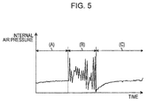
- FIG. 5 illustrates changes in internal air pressure during an operation when the waterproof cap is fitted normally.
- the horizontal axis in FIG. 5 represents time and the vertical axis in FIG. 5 represents the air pressure measured by the air pressure sensor 8 when the waterproof cap 3 is fitted normally as the internal pressure of the housing inside 1d.
- the air pressure of the housing inside 1d exhibits greater change than the time period illustrated by (A) in FIG. 5 when the user operates the mobile terminal device 1.
- the air pressure of the housing inside 1d transitions gradually to the atmospheric pressure when the user has stopped operating the mobile terminal device 1.
- FIG. 6 describes changes in internal air pressure when the waterproof cap is fitted normally.
- the horizontal axis in FIG. 6 represents time and the vertical axis in FIG. 6 represents the air pressure measured by the air pressure sensor 8 as the internal pressure of the housing inside 1d in the same way as FIG. 5 .
- the air pressure measured by the air pressure sensor 8 when the waterproof cap 3 is open is plotted in (D) in FIG. 6
- the air pressure measured by the air pressure sensor 8 when the waterproof cap 3 is fitted normally is plotted in (E) in FIG. 6 .
- the amount of fluctuation of the air pressure is approximately 0 percent when the waterproof cap 3 is open since air pressure of the housing inside 1d is kept in a state of equilibrium with the atmospheric pressure.
- the air pressure of the housing inside 1d rises greatly and then transitions to the atmospheric pressure.
- the air pressure of the housing inside 1d changes greatly in comparison to the time period illustrated in (D) in FIG. 6 .
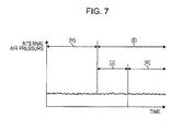
- FIG. 7 illustrates changes in internal air pressure when the waterproof cap is fitted abnormally.
- the horizontal axis in FIG. 7 represents time and the vertical axis in FIG. 7 represents the air pressure measured by the air pressure sensor 8 as the internal pressure of the housing inside 1d in the same way as FIG. 5 .
- the air pressure measured by the air pressure sensor 8 when the waterproof cap 3 is open is plotted in (H) in FIG. 7
- the air pressure measured by the air pressure sensor 8 when the waterproof cap 3 is closed but is not fitted normally is plotted in (I) in FIG. 7 .
- the air pressure sensor 8 measures a larger amount of fluctuation of air pressure than that of the atmospheric pressure during a user operation when the waterproof caps 3 and 4 and the battery cap 5 are fitted normally. Conversely, the air pressure sensor 8 measures the same degree of fluctuation between the atmospheric pressure and the air pressure when the waterproof caps 3 or 4 or the battery cap 5 is not fitted normally. As a result, the detecting unit 13 is able to determine that the waterproof caps 3 and 4 and the battery cap 5 are not fitted normally when the amount of fluctuation of the air pressure measured by the air pressure sensor 8 when the waterproof caps 3 or 4 or the battery cap 5 is open is used as the specific value.
- the output unit 14 outputs the determination result from the detecting unit 13 to the touch panel 2 to notify the user the determination result. For example, when the waterproof caps 3 or 4 or the battery cap 5 is determined by the detecting unit 13 as not being fitted normally, the output unit 14 causes the touch panel 2 to display a screen for warning the user that the waterproof cap 3 or 4 or the battery cap 5 is not fitted normally. When the detecting unit 13 determines that the waterproof caps 3 and 4 and the battery cap 5 are fitted normally, the output unit 14 causes the touch panel 2 to display a screen for notifying the user of the determination result.
- the output unit 14 may cause the touch panel 2 to display the determination result only when it is determined that the waterproof cap 3 or 4 or the battery cap 5 is not fitted properly. That is, the output unit 14 may issue a warning to the user when the detecting unit 13 determines that the waterproof cap 3 or 4 or the battery cap 5 is not fitted properly.
- FIG. 8 is a flow chart describing a flow of processing executed by the mobile terminal device according to the first embodiment.
- the mobile terminal device 1 is simply described as a terminal in FIG. 8 .
- the mobile terminal device 1 executes the following processing when an operation is conducted (operation S101).
- the mobile terminal device 1 determines whether the user is operating the mobile terminal device 1 (operation S102). If it is determined that the mobile terminal device 1 is being operated by the user (operation S102: Yes), the mobile terminal device 1 activates the air pressure sensor 8 to measure the air pressure of the housing inside 1d during a certain period of time (operation S103). The mobile terminal device 1 then calculates an amount of fluctuation ⁇ P of the air pressure from the air pressure measured during the certain period of time (operation S104).
- the mobile terminal device 1 determines whether the calculated amount of fluctuation ⁇ P of the air pressure is larger than a specific value. For example, the mobile terminal device 1 determines whether the amount of fluctuation ⁇ P is greater than a specific value P B that is an amount of fluctuation of the air pressure measured when the waterproof cap 3 or 4 or the battery cap 5 is open (operation S105).
- the mobile terminal device 1 determines that the calculated amount of fluctuation ⁇ P of the air pressure is equal to or less than the specific value P B (operation S105: No)
- the mobile terminal device 1 notifies the user the fact that the waterproof cap 3 or 4 or the battery cap 5 is not fitted normally by issuing a warning (operation S106).
- the mobile terminal device 1 ends the operation of the air pressure sensor 8 and finishes the measuring of the air pressure of the housing inside 1d (operation S107), and the processing is finished.
- the processing is finished. Moreover, if the mobile terminal device 1 determines that the amount of fluctuation ⁇ P is greater than the specific value P B (operation S105: Yes), the processing is finished.
- the mobile terminal device 1 uses the air pressure sensor 8 to measure the air pressure of the housing inside 1d.
- the mobile terminal device 1 further detects whether the housing inside 1d is sealed based on changes (amount of fluctuation) in the air pressure when the user is performing an operation.
- the mobile terminal device 1 then notifies the user of the detection result.
- the mobile terminal device 1 is able to notify the user whether or not the waterproof cap 3 or 4 is securely fitted. Moreover, since the mobile terminal device 1 uses the air pressure sensor 8 that is used as an altimeter or for weather forecasting for measuring the air pressure of the housing inside 1d, the mobile terminal device 1 is able to determine whether or not the waterproof cap 3 or 4 is securely fitted without increasing the size of the device.
- the mobile terminal device 1 determines that the housing inside 1d is not sealed when the amount of fluctuation of the air pressure measured within the certain time period is smaller than a specific value. As a result, the mobile terminal device 1 is able to accurately determine if the housing inside 1d is sealed or not.
- the mobile terminal device 1 sets the amount of fluctuation of the air pressure in the housing inside 1d when the waterproof caps 3 and 4 and the battery cap 5 are not sealed as the specific value. That is, the mobile terminal device 1 determines that the housing inside 1d is not sealed when the amount of fluctuation of the air pressure measured within a certain time period is less than the amount of fluctuation of the air pressure in the housing inside 1d when the waterproof cap 3 or 4 or the battery cap 5 is open. As a result, the mobile terminal device 1 is able to accurately determine whether the housing inside 1d is sealed or not regardless of the surrounding environment.
- the mobile terminal device 1 may falsely determine that the housing inside 1d is sealed when the mobile terminal device 1 is used in a location where the amount of fluctuation of the atmospheric pressure is large even though the housing inside 1d is not sealed.
- the mobile terminal device 1 measures the amount of fluctuation of the atmospheric pressure in a location that the mobile terminal device 1 is being used and sets the measurement result as the specific value in order to determine whether the housing inside 1d is sealed or not. Consequently, the mobile terminal device 1 uses the specific value based on the amount of fluctuation of the air pressure in accordance with the surrounding environment to determine whether or not the housing inside 1d is sealed and thus is able to reduce a false determination.
- the mobile terminal device 1 detects that the mobile terminal device 1 is being operated by the user, the mobile terminal device 1 starts to measure the air pressure of the housing inside 1d. As a result, the mobile terminal device 1 is able to reduce power consumption. That is, the air pressure sensor 8 measures the air pressure at a sampling rate higher than a sampling rate for calculating the altitude in order to measure the fluctuation of the air pressure while being operated by the user. As a result, the power consumption of the mobile terminal device 1 increases when the air pressure sensor 8 is being constantly operated.
- the mobile terminal device 1 activates the air pressure sensor 8 upon an operation, such as creating an email message, of the mobile terminal device 1 by the user to measure the fluctuation of the air pressure while the user is operating the mobile terminal device 1, the mobile terminal device 1 is able to reduce power consumption.
- the mobile terminal device 1 has been described in the abovementioned first embodiment as measuring the air pressure of the housing inside 1d upon receiving an operation by the user.
- the embodiment is not limited as such.
- the mobile terminal device 1 may not measure the air pressure when a function to be used when the waterproof cap 3 is open is in operation such as when recharging or when sending or receiving data through the USB, and thus the power consumption may be reduced further.
- the mobile terminal device 1 may not measure the air pressure when a function to be used when the waterproof cap 4 is open is in operation such as a music player or a communication or video browsing application, thus the power consumption may be reduced further.
- FIG. 9 is a flow chart describing a variation in processing executed by the mobile terminal device. Operations S201 and S203 to S208 in the processing described in FIG. 9 are the same as operations S101 to S107 in FIG. 8 , and explanations thereof will be omitted.
- the mobile terminal device 1 determines whether a function to be used when the waterproof cap 3 or 4 is open is being operated (operation S202).
- the mobile terminal device 1 identifies the applications being operated through a task manager and the like, and determines whether the identified applications include an application to be used when the waterproof cap 3 or 4 is open.
- operation S202: Yes When a function to be used when the waterproof cap 3 or 4 is open is being operated (operation S202: Yes), the mobile terminal device 1 then finishes the processing without activating the air pressure sensor 8. Conversely, if a function to be used when the waterproof cap 3 or 4 is open is not being operated (operation S202: No), operation S203 is then executed.
- the mobile terminal device 1 determines whether a function to be used when the waterproof cap 3 or 4 is open is being operated, and the air pressure of the housing inside 1d is measured only when a function to be used when the waterproof cap 3 or 4 is open is not being operated. As a result, the mobile terminal device 1 is able to further reduce power consumption.
- the abovementioned mobile terminal device 1 issues a warning to the user that the waterproof cap 3 or 4 or the battery cap 5 is not fitted.
- the embodiment is not limited as such.
- the mobile terminal device 1 activates the air pressure sensor 8 to measure the air pressure of the housing inside 1d at a certain sampling rate during a certain time period ⁇ t.
- the mobile terminal device 1 calculates the amount of fluctuation ⁇ P of the air pressure from the measured air pressure, and when a value ⁇ P A that is the amount of fluctuation ⁇ P divided by ⁇ t is less than the specific value P B , the mobile terminal device 1 issues a warning to the user that the waterproof cap 3 or 4 or the battery cap 5 is not fitted.
- the mobile terminal device 1 measures the air pressure of the housing inside 1d a plurality of times at different timings and then calculates the amount of fluctuation ⁇ P of the air pressure from the measured air pressures.
- the mobile terminal device 1 may issue a warning to the user that the waterproof cap 3 or 4 or the battery cap 5 is not fitted.
- the mobile terminal device 1 may use a value other than a fluctuation of the air pressure of the housing inside 1d measured when the waterproof cap 3 or 4 is open, as the specific value P B .
- the mobile terminal device 1 measures the air pressure of the housing inside 1d for the certain time period and then determines whether the atmospheric pressures of the housing inside 1d and of the outside housing have settled into a state of equilibrium from the measured air pressure values.
- the mobile terminal device 1 determines that the atmospheric pressures of the housing inside 1d and from outside of the housing have settled into a state of equilibrium
- the mobile terminal device 1 measures the amount of fluctuation of the air pressure in the housing inside 1d and may use the measured amount of fluctuation of the air pressure as the specific value P B .
- the mobile terminal device 1 may also calculate the specific value P B based on amounts of fluctuation of the air pressure measured a plurality of times.
- the mobile terminal device 1 may also correct the values of the amount of fluctuation ⁇ P, the amount of fluctuation ⁇ P A , and the specific value P B in consideration of the temperature or the altitude and the like.
- the mobile terminal device 1 may detect that the waterproof caps 3 or 4 or the battery cap 5 are not sealed in order to measure the amount of fluctuation of the air pressure while the waterproof caps 3 or 4 or the battery cap 5 are not sealed. That is, when the amount of fluctuation ⁇ P of the air pressure is less than the specific value, the mobile terminal device 1 may detect that the waterproof caps 3 or 4 or the battery cap 5 are not sealed, and in such a case, may measure the air pressure and calculate the value of the specific value P B .
- the mobile terminal device 1 may determine that the housing inside 1d is not sealed. For example, when ear phones, a USB connector, or a recharging connector is inserted into any of the terminals, the mobile terminal device 1 may determine that the waterproof cap 3 or 4 is open.
- the mobile terminal device 1 may determine that the waterproof cap 3 or 4 is open.
- the mobile terminal device 1 may measure the air pressure of the housing inside 1d and set the measured value as the specific value P B .
- the abovementioned mobile terminal device 1 has the air pressure sensor 8 used as an altimeter and used for weather forecasting.
- the embodiment is not limited as such.
- the mobile terminal device 1 may have an air pressure sensor for determining whether or not the waterproof cap 3 and the like is fitted instead of the air pressure sensor used as the altimeter or for weather forecasting.
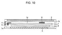
- FIG. 10 illustrates an example of an internal configuration of the mobile terminal device according to the second embodiment.
- the mobile terminal device 1 may not have the vent hole 1b or the waterproof film 1c and may not have the function for an altimeter or for weather forecasting. That is, the air pressure sensor 8 may be installed in the housing inside 1d so that the mobile terminal device 1 is able to determine whether the waterproof cap 3 is fitted normally.
- the mobile terminal device 1 activates the air pressure sensor 8 to measure the air pressure of the housing inside 1d upon receiving an operation by the user.
- the embodiment is not limited as such.
- the mobile terminal device 1 may normally activate the air pressure sensor 8 at a first sampling rate that is desired for enabling the altimeter or the weather forecasting function.
- the mobile terminal device 1 When the mobile terminal device 1 determines that the terminal is being operated by the user, the mobile terminal device 1 activates the air pressure sensor 8 to measure the air pressure of the housing inside 1d at a second sampling rate with a value higher than the first sampling rate. Then, the mobile terminal device 1 may reduce the amount of power consumption by returning the sampling rate of the air pressure sensor 8 to the first sampling rate.
- the abovementioned functions of the mobile terminal device 1 may be used for inspections such as sealing state inspections, for example, to determine if a crack is present in the housing 1a in addition to determining whether the waterproof caps are fitted securely.
- a user presses the touch panel 2 to apply a force to the mobile terminal device 1 while covering the vent hole 1b with a finger during a shipment inspection of the mobile terminal device 1.
- the mobile terminal device 1 uses the air pressure sensor 8 to measure the air pressure of the housing inside 1d and may display the fact that the product is abnormal on the touch panel 2 if the amount of fluctuation of the measured air pressure exceeds a specific value. By executing this processing, the mobile terminal device 1 may easily be subject to a product inspection for shipping.
- the abovementioned mobile terminal device 1 determines whether the waterproof caps 3 and 4 and the battery cap 5 are fitted normally in accordance with the amount of fluctuation of the air pressure of the housing inside 1d measured when the touch panel 2 is operated by the user.
- the embodiment is not limited as such. That is, if the mobile terminal device 1 has a physical button or other optional input device, the mobile terminal device 1 may make the determination in accordance with the amount of fluctuation of the air pressure of the housing inside 1d measured when the user operates the optional input device.
- the functions demonstrated by the mobile terminal device 1 described in the above embodiments may be realized by a computer in the mobile terminal device 1 that executes a previously prepared detection program.
- An example of a computer of the above mobile terminal device 1 executing a detection program that has the same functions is described hereinbelow with reference to FIG. 11.
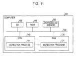
- FIG. 11 illustrates an example of a computer for executing a detection program.
- a computer 100 exemplified in FIG. 11 has a read-only memory (ROM) 110, a random access memory (RAM) 120, an air pressure sensor 130, and a central processing unit (CPU) 140 interconnected with a bus 160.
- the computer 100 exemplified in FIG. 11 has an input/output (I/O) 150 connected to the CPU 140 with the bus 160.
- a detection program 121 is previously held in the RAM 120.
- the CPU 140 reads and executes the detection program 121 from the RAM 120 so that the detection program 121 functions as a detection process 141 in the example illustrated in FIG. 11 .
- the detection process 141 demonstrates the same functions as the receiving unit 11, the measuring unit 12, the detecting unit 13 and the output unit 14 illustrated in FIG. 4 .
- the detection program described in the present embodiment may be realized by executing a program prepared in advance using a computer such as a personal computer or a workstation. Such a program may be distributed to the computer through a communication network such as the internet and the like.
- the program is recorded onto a computer-readable recording medium such as a hard disk, a flexible disk (FD), a compact disk read-only memory (CD-ROM), a magnetic-optical disk (MO), or a digital versatile disk (DVD) and the like.
- the program may be executed by the computer by being read from the recording medium.
- the computer 100 may use an arithmetic device such as a MPU or a FPGA instead of the CPU to execute the detection program 121.
- the above detection program 121 may be saved onto the RAM 120 or the ROM 110, for example, and may be executed by the CPU 140 with another method.
- the programs may be stored on a "portable physical medium" such as a flexible disk (FD), a compact disk read-only memory (CD-ROM), a digital versatile disk (DVD), a magnetic-optical disk (MO), or an IC card and the like.
- the computer 100 then may obtain the programs from the portable physical medium and execute the programs. Moreover, the programs may be stored on another computer or a server device and obtained through a public telephone line, the Internet, a LAN, or a wide area network (WAN) and the like.
- WAN wide area network
Landscapes
- Engineering & Computer Science (AREA)
- Signal Processing (AREA)
- Physics & Mathematics (AREA)
- General Physics & Mathematics (AREA)
- Computer Networks & Wireless Communication (AREA)
- Business, Economics & Management (AREA)
- Emergency Management (AREA)
- Telephone Function (AREA)
- Telephone Set Structure (AREA)
Abstract
Description
- The embodiments discussed herein relate to a mobile terminal device and a sealing detection method.
- Mobile terminal devices having a waterproofing function are conventionally known among mobile terminal devices. In order to reduce the intrusion of water into the inside of a housing, such mobile terminal devices are provided with water proof caps that are openable and closeable for battery lids, earphone or charging terminals, Universal Serial Bus (USB) terminals, or various types of memory card insertion terminals.
- In this case, the mobile terminal device may be damaged when immersed in water if the waterproofing function is not demonstrated when the water proof caps for the battery lid or for the various terminals are not fitted securely. Accordingly, the mobile terminal device issues a warning to a user to securely fit the waterproof caps for the battery lid or for the various terminals with a seal applied to the screen display or the housing.
- Japanese Laid-open Patent Publication No.
2000-216555 - Accordingly, it is desirable to provide a mobile terminal device and a sealing detection method that are able to notify a user whether a waterproof cap is securely fitted.
- According to an aspect of the invention, a mobile terminal device includes: a housing; a measuring unit configured to measure an air pressure inside the housing; a detecting unit configured to detect whether the housing is sealed based on a change in the air pressure measured by the measuring unit while an operation is being conducted by a user; and a notifying unit configured to notify the user of a detection result of the detecting unit.
-
-
FIG. 1 illustrates an example of a mobile terminal device according to a first embodiment; -
FIG. 2 illustrates an example of an internal configuration of the mobile terminal device according to the first embodiment; -
FIG. 3 illustrates a hardware configuration of the mobile terminal device according to the first embodiment; -
FIG. 4 illustrates a functional configuration of a controller according to the first embodiment; -
FIG. 5 illustrates changes in internal air pressure during operation when a waterproof cap is fitted normally; -
FIG. 6 illustrates changes in internal air pressure when a waterproof cap is fitted normally; -
FIG. 7 illustrates changes in internal air pressure when a waterproof cap is fitted abnormally; -
FIG. 8 is a flow chart describing a flow of processing executed by the mobile terminal device according to the first embodiment; -
FIG. 9 is a flow chart describing a variation in processing executed by the mobile terminal device; -
FIG. 10 illustrates an example of an internal configuration of the mobile terminal device according to a second embodiment; and -
FIG. 11 illustrates an example of a computer for executing a detection program. - The conventional mobile terminal device issues a warning to the user to securely fit the battery lid or the water proof caps of the terminals. And the conventional mobile terminal relies on touch as to whether the battery lid or the water proof caps of the terminals are securely fitted or not when the user fits the waterproof caps on. Accordingly, it is difficult to determine whether the waterproof caps are securely fitted or not. As a result, when, for example, foreign matter is adhered to the waterproof cap, the waterproofing function is not demonstrated since a gap is present even if the waterproof cap seems to be fitted onto the housing, and therefore damage may occur to the mobile terminal device if immersed in water.
- Embodiments of a mobile terminal device and a sealing detection method that are able to notify a user whether a waterproof cap is securely fitted are described in detail hereinbelow with reference to the drawings. The following embodiments are not limited to the features disclosed herein. The embodiments may be combined as appropriate within a consistent scope.
- A mobile terminal device having a touch panel such as a smartphone or a tablet terminal will be described in the present embodiment as an example of a mobile terminal device disclosed in the present application.
FIG. 1 illustrates an example of a mobile terminal device according to a first embodiment. A front side external perspective view of amobile terminal device 1 according to the first embodiment is depicted inFIG. 1 . - As illustrated in
FIG. 1 , themobile terminal device 1 has atouch panel 2 andwaterproof caps 3 and 4. Themobile terminal device 1 is a smartphone that is connectable to any mobile communication network such as the third generation (3G), 4G, or long-term evolution (LTE) services. - The
touch panel 2 is an input/output device attached to a surface of themobile terminal device 1 and has a liquid crystal panel for displaying various types of information and a touch sensor for detecting touch from a finger of a user and receiving an input operation. For example, thetouch panel 2 is an electrostatic capacitive touch panel. - The
waterproof caps 3 and 4 are cover members that can be opened and closed by the user and have a waterproofing function. For example, the waterproof cap 3 protects a terminal for connecting a Universal Serial Bus (USB). Further, thewaterproof cap 4 protects an insertion terminal (jack) for inserting various types of earphone plugs. - Next, an example of an internal configuration of the
mobile terminal device 1 will be explained withFIG. 2. FIG. 2 illustrates an example of an internal configuration of the mobile terminal device according to the first embodiment. A cross-sectional view of themobile terminal device 1 is depicted inFIG. 2 . - As illustrated in
FIG. 2 , themobile terminal device 1 has ahousing 1a, avent hole 1b, awaterproof film 1c, abattery cap 5, abattery 6, acircuit board 7, anair pressure sensor 8, and an external connectingpart 9. Thehousing 1a is a cladding that forms a frame of themobile terminal device 1 and has a waterproofing function. Thevent hole 1b is provided in thehousing 1a and is installed to allow an air pressure of a housing inside 1d to match the air pressure outside of the housing. Thewaterproof film 1c is a film-like member installed at the housing inside 1d side of thevent hole 1b for reducing the intrusion of water from thevent hole 1b. Thewaterproof film 1c is a member that has air permeability but reduces the intrusion of a liquid such as water. - The
battery cap 5 is a lid member that can be opened and closed when installing or removing thebattery 6 and has the same waterproofing function as thewaterproof caps 3 and 4. In this way, themobile terminal device 1 has thehousing 1a, thewaterproof caps 3 and 4, and thebattery cap 5 that all have the waterproofing function and thus reduce the intrusion of water into the housing inside 1d. - The
battery 6 is an electric power source device for themobile terminal device 1. Thecircuit board 7 is a board on which are installed electronic devices that themobile terminal device 1 uses to demonstrate various functions. For example, thecircuit board 7 has arithmetic processors such as a central processing unit (CPU) or a digital signal processor (DSP), storage devices such as a flash memory, and various input/output (I/O) devices such as the USB terminal. - The
air pressure sensor 8 is installed in themobile terminal device 1 and is, for example, an air pressure sensor used in an altimeter. For example, themobile terminal device 1 measures the atmospheric pressure in the housing inside 1d that enters a state of equilibrium with the outside of the housing via thevent hole 1b and thewaterproof film 1c. Themobile terminal device 1 uses the measurement result to calculate the altitude in which themobile terminal device 1 is present. Theair pressure sensor 8 may be, in addition to the altimeter, an air pressure sensor used by an application for weather forecasting. - The external connecting
part 9 is a connector for relaying a connection between the outside of themobile terminal device 1 and thecircuit board 7, and is, for example, an insertion terminal for inserting a earphone plug. When the user inserts an earphone plug into the external connectingpart 9 to listen to music, the user uses themobile terminal device 1 with thewaterproof cap 4 in an open state. - Next, an example of a hardware configuration of the
mobile terminal device 1 will be described withFIG. 3. FIG. 3 illustrates a hardware configuration of the mobile terminal device according to the first embodiment. As illustrated inFIG. 3 , themobile terminal device 1 has acontroller 10 connected to thetouch panel 2, theair pressure sensor 8, the external connectingpart 9, and amemory 20. Thecontroller 10 and thememory 20 are formed on thecircuit board 7 depicted inFIG. 2 . - The
controller 10 executes processing for demonstrating the various functions of the mobileterminal device 1. For example, thecontroller 10 has an arithmetic processor such as the CPU, the DSP, or a field programmable gate array (FPGA), and controls the operations of thetouch panel 2, theair pressure sensor 8, and the external connectingpart 9 by executing programs stored in thememory 20. - The
memory 20 stores various programs and various thresholds and the like. A synchronous dynamic random access memory (SDRAM), a random access memory (RAM), a read-only memory (ROM), or a flash memory may be considered as examples of thememory 20. - The
memory 20 stores a detection program for detecting whether thewaterproof caps 3 and 4 and thebattery cap 5 in the mobileterminal device 1 are fitted or not. Thecontroller 10 enables the functional configuration illustrated inFIG. 4 by executing a detection program stored in thememory 20. -
FIG. 4 illustrates a functional configuration of a controller according to the first embodiment. For example, thecontroller 10 has a receivingunit 11, a measuringunit 12, a detectingunit 13, and anoutput unit 14. The receivingunit 11 receives operations from the user via thetouch panel 2. The receivingunit 11 notifies the various functions about the contents of the received operation and sends an instruction to the measuringunit 12 to execute an air pressure measuring process upon receiving an operation from the user. - The measuring
unit 12 uses theair pressure sensor 8 to measure the air pressure of the housing inside 1d. For example, when the measuringunit 12 is instructed to execute the air pressure measuring process by the receivingunit 11, the measuringunit 12 activates theair pressure sensor 8 to measure the air pressure of the housing inside 1d during a certain time period. That is, the measuringunit 12 measures the air pressure of the housing inside 1d while the user is using thetouch panel 2 to operate the mobileterminal device 1. To provide a detailed example, the measuringunit 12 measures the air pressure of the housing inside 1d at a measurement frequency of 1 second intervals. The measuringunit 12 outputs the measurement result to the detectingunit 13 and stops the operation of theair pressure sensor 8. - The detecting
unit 13 detects whether the housing inside 1d of the mobileterminal device 1 is sealed based on a fluctuation in the air pressure measured by the measuringunit 12. Specifically, the detectingunit 13 determines that the housing inside 1d of the mobileterminal device 1 is not sealed when the amount of fluctuation of the air pressure measured within the certain time period is smaller than a specific value. Conversely, the detectingunit 13 determines that the housing inside 1d of the mobileterminal device 1 is sealed when the amount of fluctuation of the air pressure measured within the certain time period is greater than the specific value. The detectingunit 13 then notifies theoutput unit 14 about the determination result. - A mechanism for determining whether the housing inside 1d is sealed based on fluctuation of the air pressure measured by the measuring
unit 12 will be described hereinbelow. As illustrated inFIG. 2 , the mobileterminal device 1 has thevent hole 1b in order to allow the atmospheric pressure of the housing inside 1d match the atmospheric pressure outside of the housing. However, the mobileterminal device 1 has a configuration for reducing the intrusion of water, such as thewaterproof film 1c, for maintaining the waterproofing capability. As a result, when thewaterproof caps 3 and 4 and thebattery cap 5 are securely fitted and the housing inside 1d is in a sealed state, a certain amount of time is desired for the atmospheric pressure of the housing inside 1d and the atmospheric pressure outside of the housing to reach a state of equilibrium. - Moreover, when the user operates the mobile
terminal device 1 via thetouch panel 2, the volume of the housing inside 1d changes due to thehousing 1a being bent. Because the mobileterminal device 1 has a limited size, the volume of the housing inside 1d fluctuates by a relatively large proportion. As a result, when the user performs an operation while thewaterproof caps 3 and 4 and thebattery cap 5 are securely fitted, the atmospheric pressure of the housing inside 1d fluctuates more than the atmospheric pressure outside of the housing. Conversely, if thewaterproof caps 3 and 4 and thebattery cap 5 are not fitted, the atmospheric pressure of the housing inside 1d does not fluctuate very much even when the user performs an operation since the atmospheric pressure of the housing inside 1d and the atmospheric pressure outside of the housing reach the state of equilibrium instantly. - As a result, the detecting
unit 13 is able to determine whether thewaterproof caps 3 and 4 and thebattery cap 5 are securely fitted in accordance with the fluctuation of the atmospheric pressure in the housing inside 1d when the user operates the mobileterminal device 1. Specifically, the detectingunit 13 is able to determine that thewaterproof caps 3 and 4 and thebattery cap 5 are not securely fitted when the amount of fluctuation of the air pressure measured while the user is operating the mobileterminal device 1 is less than a specific value. - Any value may be used as the specific value used by the detecting
unit 13 in accordance with the stiffness and the size of the mobileterminal device 1. For example, the detectingunit 13 may determine that thewaterproof caps 3 or 4 or thebattery cap 5 are not securely fitted when the amount of fluctuation of the air pressure per 1 second during a user operation exceeds 5 percent. For example, the detectingunit 13 may use the amount of fluctuation of the air pressure measured by theair pressure sensor 8 in a state in which thewaterproof caps 3 or 4 or thebattery cap 5 may not be fitted, as the specific value. - Moreover, an amount of fluctuation calculated by any method may be used in accordance with the specific value for comparison as the amount of fluctuation of the air pressure used by the detecting
unit 13. For example, the detectingunit 13 may use a difference between a maximum value and a minimum value among air pressure values measured by theair pressure sensor 8 during a certain time period, as the amount of fluctuation of the air pressure. For example, the detectingunit 13 may use a difference among air pressure values measured continuously as the amount of fluctuation of the air pressure. - Examples of air pressure values measured by the
air pressure sensor 8 when the waterproof cap 3 is securely fitted and air pressure values measured by theair pressure sensor 8 when the waterproof cap 3 is not securely fitted will be described hereinbelow with reference toFIGs. 5 to 7 . In the following explanations, it is assumed that thewaterproof cap 4 and thebattery cap 5 are fitted normally. -
FIG. 5 illustrates changes in internal air pressure during an operation when the waterproof cap is fitted normally. The horizontal axis inFIG. 5 represents time and the vertical axis inFIG. 5 represents the air pressure measured by theair pressure sensor 8 when the waterproof cap 3 is fitted normally as the internal pressure of the housing inside 1d. For example, only a small amount of change in the air pressure of the housing inside 1d occurs in the time period (A) inFIG. 5 since the user is not operating the mobileterminal device 1. However, as illustrated in (B) inFIG. 5 , the air pressure of the housing inside 1d exhibits greater change than the time period illustrated by (A) inFIG. 5 when the user operates the mobileterminal device 1. Further, as illustrated in (C) inFIG. 5 , the air pressure of the housing inside 1d transitions gradually to the atmospheric pressure when the user has stopped operating the mobileterminal device 1. -
FIG. 6 describes changes in internal air pressure when the waterproof cap is fitted normally. The horizontal axis inFIG. 6 represents time and the vertical axis inFIG. 6 represents the air pressure measured by theair pressure sensor 8 as the internal pressure of the housing inside 1d in the same way asFIG. 5 . The air pressure measured by theair pressure sensor 8 when the waterproof cap 3 is open is plotted in (D) inFIG. 6 , and the air pressure measured by theair pressure sensor 8 when the waterproof cap 3 is fitted normally is plotted in (E) inFIG. 6 . - For example, as illustrated in (D) in
FIG. 6 , the amount of fluctuation of the air pressure is approximately 0 percent when the waterproof cap 3 is open since air pressure of the housing inside 1d is kept in a state of equilibrium with the atmospheric pressure. As illustrated in (F) inFIG. 6 , when the waterproof cap 3 is fitted, the air pressure of the housing inside 1d rises greatly and then transitions to the atmospheric pressure. As illustrated in (G) inFIG. 6 , when the user operates the mobileterminal device 1, the air pressure of the housing inside 1d changes greatly in comparison to the time period illustrated in (D) inFIG. 6 . -
FIG. 7 illustrates changes in internal air pressure when the waterproof cap is fitted abnormally. The horizontal axis inFIG. 7 represents time and the vertical axis inFIG. 7 represents the air pressure measured by theair pressure sensor 8 as the internal pressure of the housing inside 1d in the same way asFIG. 5 . The air pressure measured by theair pressure sensor 8 when the waterproof cap 3 is open is plotted in (H) inFIG. 7 , and the air pressure measured by theair pressure sensor 8 when the waterproof cap 3 is closed but is not fitted normally is plotted in (I) inFIG. 7 . - For example, as illustrated in (H) in
FIG. 7 when the waterproof cap 3 is open, the air pressure changes very little since the air pressure of the housing inside 1d is kept in a state of equilibrium with the atmospheric pressure. As illustrated in (J) inFIG. 7 , when the waterproof cap 3 is closed but is not fitted normally, the air pressure of the housing inside 1d changes very little since air leaks in from gap between the waterproof cap 3 and thehousing 1a. As illustrated in (K) inFIG. 7 , even if the user operates the mobileterminal device 1, the air pressure of the housing inside 1d changes very little since the air pressure of the housing inside 1d and the atmospheric pressure transition instantly to a state of equilibrium when the waterproof cap is not fitted normally. - In this way, the
air pressure sensor 8 measures a larger amount of fluctuation of air pressure than that of the atmospheric pressure during a user operation when thewaterproof caps 3 and 4 and thebattery cap 5 are fitted normally. Conversely, theair pressure sensor 8 measures the same degree of fluctuation between the atmospheric pressure and the air pressure when thewaterproof caps 3 or 4 or thebattery cap 5 is not fitted normally. As a result, the detectingunit 13 is able to determine that thewaterproof caps 3 and 4 and thebattery cap 5 are not fitted normally when the amount of fluctuation of the air pressure measured by theair pressure sensor 8 when thewaterproof caps 3 or 4 or thebattery cap 5 is open is used as the specific value. - The following explanation returns to
FIG. 4 . Theoutput unit 14 outputs the determination result from the detectingunit 13 to thetouch panel 2 to notify the user the determination result. For example, when thewaterproof caps 3 or 4 or thebattery cap 5 is determined by the detectingunit 13 as not being fitted normally, theoutput unit 14 causes thetouch panel 2 to display a screen for warning the user that thewaterproof cap 3 or 4 or thebattery cap 5 is not fitted normally. When the detectingunit 13 determines that thewaterproof caps 3 and 4 and thebattery cap 5 are fitted normally, theoutput unit 14 causes thetouch panel 2 to display a screen for notifying the user of the determination result. - The
output unit 14 may cause thetouch panel 2 to display the determination result only when it is determined that thewaterproof cap 3 or 4 or thebattery cap 5 is not fitted properly. That is, theoutput unit 14 may issue a warning to the user when the detectingunit 13 determines that thewaterproof cap 3 or 4 or thebattery cap 5 is not fitted properly. - Next, a flow of processing executed by the mobile
terminal device 1 will be explained with reference toFIG. 8. FIG. 8 is a flow chart describing a flow of processing executed by the mobile terminal device according to the first embodiment. The mobileterminal device 1 is simply described as a terminal inFIG. 8 . For example, the mobileterminal device 1 executes the following processing when an operation is conducted (operation S101). - First, the mobile
terminal device 1 determines whether the user is operating the mobile terminal device 1 (operation S102). If it is determined that the mobileterminal device 1 is being operated by the user (operation S102: Yes), the mobileterminal device 1 activates theair pressure sensor 8 to measure the air pressure of the housing inside 1d during a certain period of time (operation S103). The mobileterminal device 1 then calculates an amount of fluctuation ΔP of the air pressure from the air pressure measured during the certain period of time (operation S104). - Next, the mobile
terminal device 1 determines whether the calculated amount of fluctuation ΔP of the air pressure is larger than a specific value. For example, the mobileterminal device 1 determines whether the amount of fluctuation ΔP is greater than a specific value PB that is an amount of fluctuation of the air pressure measured when thewaterproof cap 3 or 4 or thebattery cap 5 is open (operation S105). - When the mobile
terminal device 1 determines that the calculated amount of fluctuation ΔP of the air pressure is equal to or less than the specific value PB (operation S105: No), the mobileterminal device 1 notifies the user the fact that thewaterproof cap 3 or 4 or thebattery cap 5 is not fitted normally by issuing a warning (operation S106). Next, the mobileterminal device 1 ends the operation of theair pressure sensor 8 and finishes the measuring of the air pressure of the housing inside 1d (operation S107), and the processing is finished. - Conversely, if the mobile
terminal device 1 determines that the mobileterminal device 1 is not being operated by the user (operation S102: No), the processing is finished. Moreover, if the mobileterminal device 1 determines that the amount of fluctuation ΔP is greater than the specific value PB (operation S105: Yes), the processing is finished. - As described above, the mobile
terminal device 1 uses theair pressure sensor 8 to measure the air pressure of the housing inside 1d. The mobileterminal device 1 further detects whether the housing inside 1d is sealed based on changes (amount of fluctuation) in the air pressure when the user is performing an operation. The mobileterminal device 1 then notifies the user of the detection result. - As a result, the mobile
terminal device 1 is able to notify the user whether or not thewaterproof cap 3 or 4 is securely fitted. Moreover, since the mobileterminal device 1 uses theair pressure sensor 8 that is used as an altimeter or for weather forecasting for measuring the air pressure of the housing inside 1d, the mobileterminal device 1 is able to determine whether or not thewaterproof cap 3 or 4 is securely fitted without increasing the size of the device. - The mobile
terminal device 1 determines that the housing inside 1d is not sealed when the amount of fluctuation of the air pressure measured within the certain time period is smaller than a specific value. As a result, the mobileterminal device 1 is able to accurately determine if the housing inside 1d is sealed or not. - Moreover, the mobile
terminal device 1 sets the amount of fluctuation of the air pressure in the housing inside 1d when thewaterproof caps 3 and 4 and thebattery cap 5 are not sealed as the specific value. That is, the mobileterminal device 1 determines that the housing inside 1d is not sealed when the amount of fluctuation of the air pressure measured within a certain time period is less than the amount of fluctuation of the air pressure in the housing inside 1d when thewaterproof cap 3 or 4 or thebattery cap 5 is open. As a result, the mobileterminal device 1 is able to accurately determine whether the housing inside 1d is sealed or not regardless of the surrounding environment. - For example, if the specific value is not set appropriately, the mobile
terminal device 1 may falsely determine that the housing inside 1d is sealed when the mobileterminal device 1 is used in a location where the amount of fluctuation of the atmospheric pressure is large even though the housing inside 1d is not sealed. As a result, the mobileterminal device 1 measures the amount of fluctuation of the atmospheric pressure in a location that the mobileterminal device 1 is being used and sets the measurement result as the specific value in order to determine whether the housing inside 1d is sealed or not. Consequently, the mobileterminal device 1 uses the specific value based on the amount of fluctuation of the air pressure in accordance with the surrounding environment to determine whether or not the housing inside 1d is sealed and thus is able to reduce a false determination. - Moreover, when the mobile
terminal device 1 detects that the mobileterminal device 1 is being operated by the user, the mobileterminal device 1 starts to measure the air pressure of the housing inside 1d. As a result, the mobileterminal device 1 is able to reduce power consumption. That is, theair pressure sensor 8 measures the air pressure at a sampling rate higher than a sampling rate for calculating the altitude in order to measure the fluctuation of the air pressure while being operated by the user. As a result, the power consumption of the mobileterminal device 1 increases when theair pressure sensor 8 is being constantly operated. However, since the mobileterminal device 1 activates theair pressure sensor 8 upon an operation, such as creating an email message, of the mobileterminal device 1 by the user to measure the fluctuation of the air pressure while the user is operating the mobileterminal device 1, the mobileterminal device 1 is able to reduce power consumption. - The embodiments explained up to this point may be implemented in various different forms other than the abovementioned embodiments. Another embodiment included in the present disclosure will be described hereinbelow as the second embodiment.
- The mobile
terminal device 1 has been described in the abovementioned first embodiment as measuring the air pressure of the housing inside 1d upon receiving an operation by the user. However, the embodiment is not limited as such. For example, the mobileterminal device 1 may not measure the air pressure when a function to be used when the waterproof cap 3 is open is in operation such as when recharging or when sending or receiving data through the USB, and thus the power consumption may be reduced further. Moreover, the mobileterminal device 1 may not measure the air pressure when a function to be used when thewaterproof cap 4 is open is in operation such as a music player or a communication or video browsing application, thus the power consumption may be reduced further. - A description of a variation in the processing executed by the mobile
terminal device 1 will be described with reference toFIG. 9. FIG. 9 is a flow chart describing a variation in processing executed by the mobile terminal device. Operations S201 and S203 to S208 in the processing described inFIG. 9 are the same as operations S101 to S107 inFIG. 8 , and explanations thereof will be omitted. - For example, when an operation of the mobile
terminal device 1 is started by the user (operation S201), the mobileterminal device 1 determines whether a function to be used when thewaterproof cap 3 or 4 is open is being operated (operation S202). To provide a detailed example, the mobileterminal device 1 identifies the applications being operated through a task manager and the like, and determines whether the identified applications include an application to be used when thewaterproof cap 3 or 4 is open. - When a function to be used when the
waterproof cap 3 or 4 is open is being operated (operation S202: Yes), the mobileterminal device 1 then finishes the processing without activating theair pressure sensor 8. Conversely, if a function to be used when thewaterproof cap 3 or 4 is open is not being operated (operation S202: No), operation S203 is then executed. - In this way, the mobile
terminal device 1 determines whether a function to be used when thewaterproof cap 3 or 4 is open is being operated, and the air pressure of the housing inside 1d is measured only when a function to be used when thewaterproof cap 3 or 4 is open is not being operated. As a result, the mobileterminal device 1 is able to further reduce power consumption. - When the amount of fluctuation ΔP of the air pressure measured by the
air pressure sensor 8 is less than the specific value PB, the abovementioned mobileterminal device 1 issues a warning to the user that thewaterproof cap 3 or 4 or thebattery cap 5 is not fitted. However, the embodiment is not limited as such. - For example, the mobile
terminal device 1 activates theair pressure sensor 8 to measure the air pressure of the housing inside 1d at a certain sampling rate during a certain time period Δt. The mobileterminal device 1 calculates the amount of fluctuation ΔP of the air pressure from the measured air pressure, and when a value ΔPA that is the amount of fluctuation ΔP divided by Δt is less than the specific value PB, the mobileterminal device 1 issues a warning to the user that thewaterproof cap 3 or 4 or thebattery cap 5 is not fitted. - Moreover, the mobile
terminal device 1 measures the air pressure of the housing inside 1d a plurality of times at different timings and then calculates the amount of fluctuation ΔP of the air pressure from the measured air pressures. When the value ΔPA that is the amount of fluctuation ΔP divided by Δt is less than the specific value PB, the mobileterminal device 1 may issue a warning to the user that thewaterproof cap 3 or 4 or thebattery cap 5 is not fitted. - Furthermore, the mobile
terminal device 1 may use a value other than a fluctuation of the air pressure of the housing inside 1d measured when thewaterproof cap 3 or 4 is open, as the specific value PB. For example, the mobileterminal device 1 measures the air pressure of the housing inside 1d for the certain time period and then determines whether the atmospheric pressures of the housing inside 1d and of the outside housing have settled into a state of equilibrium from the measured air pressure values. When the mobileterminal device 1 determines that the atmospheric pressures of the housing inside 1d and from outside of the housing have settled into a state of equilibrium, the mobileterminal device 1 measures the amount of fluctuation of the air pressure in the housing inside 1d and may use the measured amount of fluctuation of the air pressure as the specific value PB. The mobileterminal device 1 may also calculate the specific value PB based on amounts of fluctuation of the air pressure measured a plurality of times. The mobileterminal device 1 may also correct the values of the amount of fluctuation ΔP, the amount of fluctuation ΔPA, and the specific value PB in consideration of the temperature or the altitude and the like. - The mobile
terminal device 1 may detect that thewaterproof caps 3 or 4 or thebattery cap 5 are not sealed in order to measure the amount of fluctuation of the air pressure while thewaterproof caps 3 or 4 or thebattery cap 5 are not sealed. That is, when the amount of fluctuation ΔP of the air pressure is less than the specific value, the mobileterminal device 1 may detect that thewaterproof caps 3 or 4 or thebattery cap 5 are not sealed, and in such a case, may measure the air pressure and calculate the value of the specific value PB. - For example, if the
waterproof caps 3 and 4 are open, the mobileterminal device 1 may determine that the housing inside 1d is not sealed. For example, when ear phones, a USB connector, or a recharging connector is inserted into any of the terminals, the mobileterminal device 1 may determine that thewaterproof cap 3 or 4 is open. - Furthermore when, for example, an application to be executed when ear phones, a USB connector, or a recharging connector is inserted into any of the terminals is being executed, the mobile
terminal device 1 may determine that thewaterproof cap 3 or 4 is open. When thewaterproof cap 3 or 4 is detected as being open, the mobileterminal device 1 may measure the air pressure of the housing inside 1d and set the measured value as the specific value PB. - The abovementioned mobile
terminal device 1 has theair pressure sensor 8 used as an altimeter and used for weather forecasting. However, the embodiment is not limited as such. For example, the mobileterminal device 1 may have an air pressure sensor for determining whether or not the waterproof cap 3 and the like is fitted instead of the air pressure sensor used as the altimeter or for weather forecasting. - For example,
FIG. 10 illustrates an example of an internal configuration of the mobile terminal device according to the second embodiment. As illustrated inFIG. 10 , the mobileterminal device 1 may not have thevent hole 1b or thewaterproof film 1c and may not have the function for an altimeter or for weather forecasting. That is, theair pressure sensor 8 may be installed in the housing inside 1d so that the mobileterminal device 1 is able to determine whether the waterproof cap 3 is fitted normally. - Moreover, the mobile
terminal device 1 activates theair pressure sensor 8 to measure the air pressure of the housing inside 1d upon receiving an operation by the user. However, the embodiment is not limited as such. For example, the mobileterminal device 1 may normally activate theair pressure sensor 8 at a first sampling rate that is desired for enabling the altimeter or the weather forecasting function. - When the mobile
terminal device 1 determines that the terminal is being operated by the user, the mobileterminal device 1 activates theair pressure sensor 8 to measure the air pressure of the housing inside 1d at a second sampling rate with a value higher than the first sampling rate. Then, the mobileterminal device 1 may reduce the amount of power consumption by returning the sampling rate of theair pressure sensor 8 to the first sampling rate. - The abovementioned functions of the mobile
terminal device 1 may be used for inspections such as sealing state inspections, for example, to determine if a crack is present in thehousing 1a in addition to determining whether the waterproof caps are fitted securely. For example, a user presses thetouch panel 2 to apply a force to the mobileterminal device 1 while covering thevent hole 1b with a finger during a shipment inspection of the mobileterminal device 1. In this case, the mobileterminal device 1 uses theair pressure sensor 8 to measure the air pressure of the housing inside 1d and may display the fact that the product is abnormal on thetouch panel 2 if the amount of fluctuation of the measured air pressure exceeds a specific value. By executing this processing, the mobileterminal device 1 may easily be subject to a product inspection for shipping. - Moreover, the abovementioned mobile
terminal device 1 determines whether thewaterproof caps 3 and 4 and thebattery cap 5 are fitted normally in accordance with the amount of fluctuation of the air pressure of the housing inside 1d measured when thetouch panel 2 is operated by the user. However, the embodiment is not limited as such. That is, if the mobileterminal device 1 has a physical button or other optional input device, the mobileterminal device 1 may make the determination in accordance with the amount of fluctuation of the air pressure of the housing inside 1d measured when the user operates the optional input device. - The functions demonstrated by the mobile
terminal device 1 described in the above embodiments may be realized by a computer in the mobileterminal device 1 that executes a previously prepared detection program. An example of a computer of the above mobileterminal device 1 executing a detection program that has the same functions is described hereinbelow with reference toFIG. 11. FIG. 11 illustrates an example of a computer for executing a detection program. - A
computer 100 exemplified inFIG. 11 has a read-only memory (ROM) 110, a random access memory (RAM) 120, anair pressure sensor 130, and a central processing unit (CPU) 140 interconnected with abus 160. Thecomputer 100 exemplified inFIG. 11 has an input/output (I/O) 150 connected to theCPU 140 with thebus 160. - A
detection program 121 is previously held in theRAM 120. TheCPU 140 reads and executes thedetection program 121 from theRAM 120 so that thedetection program 121 functions as adetection process 141 in the example illustrated inFIG. 11 . Thedetection process 141 demonstrates the same functions as the receivingunit 11, the measuringunit 12, the detectingunit 13 and theoutput unit 14 illustrated inFIG. 4 . - The detection program described in the present embodiment may be realized by executing a program prepared in advance using a computer such as a personal computer or a workstation. Such a program may be distributed to the computer through a communication network such as the internet and the like. The program is recorded onto a computer-readable recording medium such as a hard disk, a flexible disk (FD), a compact disk read-only memory (CD-ROM), a magnetic-optical disk (MO), or a digital versatile disk (DVD) and the like. The program may be executed by the computer by being read from the recording medium.
- The
computer 100 may use an arithmetic device such as a MPU or a FPGA instead of the CPU to execute thedetection program 121. Moreover, theabove detection program 121 may be saved onto theRAM 120 or theROM 110, for example, and may be executed by theCPU 140 with another method. For example, the programs may be stored on a "portable physical medium" such as a flexible disk (FD), a compact disk read-only memory (CD-ROM), a digital versatile disk (DVD), a magnetic-optical disk (MO), or an IC card and the like. - The
computer 100 then may obtain the programs from the portable physical medium and execute the programs. Moreover, the programs may be stored on another computer or a server device and obtained through a public telephone line, the Internet, a LAN, or a wide area network (WAN) and the like.
Claims (7)
- A mobile terminal (1) device comprising:a housing (1a);a measuring unit (12) configured to measure an air pressure inside the housing (1a);a detecting unit (13) configured to detect whether the housing (1a) is sealed based on a change in the air pressure measured by the measuring unit (12) while an operation is being conducted by a user; anda notifying unit (14) configured to notify the user of a detection result of the detecting unit (13).
- The mobile terminal (1) device according to claim 1, wherein the detecting unit (13) detects that the housing (1a) is not sealed when an amount of fluctuation of the air pressure measured within a certain time period is smaller than a specific value.
- The mobile terminal (1) device according to claim 2, wherein the amount of fluctuation of the air pressure measured by the measuring unit (12) in a state in which an openable and closeable lid member provided on the housing (1a) is not sealed is set as the specific value.
- The mobile terminal device (1) according to any one of claims 1 to 3, wherein the measuring unit (12) starts measuring the air pressure inside the housing (1a) when an operation by the user is detected.
- The mobile terminal device (1) according to any one of claims 1 to 4, wherein the measuring unit (12) does not measure the air pressure inside the housing (1a) when a function to be used when an openable and closeable lid member provided on the housing (1a) is open is being operated, and measures the air pressure inside the housing (1a) when a function to be used when the openable and closeable lid member provided on the housing (1a) is open is not being operated.
- A sealing detection program that causes a computer in a mobile terminal device to:measure an air pressure inside a housing;detect whether the housing is sealed based on a change in the measured air pressure while an operation is being conducted by a user; andnotify the user of a result of the detecting.
- A sealing detection method comprising:measuring an air pressure inside a housing of a mobile terminal device;detecting whether the housing is sealed based on a change in the measured air pressure while an operation is being conducted by a user; andnotifying the user of a result of the detecting.
Applications Claiming Priority (1)
| Application Number | Priority Date | Filing Date | Title |
|---|---|---|---|
| JP2013185356A JP6244758B2 (en) | 2013-09-06 | 2013-09-06 | Portable terminal device and detection program |
Publications (2)
| Publication Number | Publication Date |
|---|---|
| EP2846516A1 true EP2846516A1 (en) | 2015-03-11 |
| EP2846516B1 EP2846516B1 (en) | 2015-12-23 |
Family
ID=51494083
Family Applications (1)
| Application Number | Title | Priority Date | Filing Date |
|---|---|---|---|
| EP14182896.2A Not-in-force EP2846516B1 (en) | 2013-09-06 | 2014-08-29 | Mobile terminal device and sealing detection method |
Country Status (3)
| Country | Link |
|---|---|
| US (1) | US9518890B2 (en) |
| EP (1) | EP2846516B1 (en) |
| JP (1) | JP6244758B2 (en) |
Cited By (5)
| Publication number | Priority date | Publication date | Assignee | Title |
|---|---|---|---|---|
| CN105258865A (en) * | 2015-06-09 | 2016-01-20 | 中山市天键电声有限公司 | High-precision waterproof test apparatus |
| CN106840543A (en) * | 2017-01-24 | 2017-06-13 | 维沃移动通信有限公司 | A kind of water inlet detecting device, the control method of mobile terminal and mobile terminal |
| CN107369300A (en) * | 2017-06-09 | 2017-11-21 | 广东小天才科技有限公司 | Electronic equipment drowning detection device and method and electronic equipment |
| CN114244946A (en) * | 2021-12-14 | 2022-03-25 | 广东明创软件科技有限公司 | Waterproof state detection method and related device |
| US20250096834A1 (en) * | 2023-09-15 | 2025-03-20 | Dongguan Shenhai Sporting Goods Co., Ltd | Tightness self-checking device for waterproof mobile phone protective case and method thereof |
Families Citing this family (10)
| Publication number | Priority date | Publication date | Assignee | Title |
|---|---|---|---|---|
| JP6170830B2 (en) * | 2013-12-20 | 2017-07-26 | 京セラ株式会社 | Portable electronic device and waterproof judgment method |
| JP6520580B2 (en) * | 2015-09-03 | 2019-05-29 | 富士通コネクテッドテクノロジーズ株式会社 | Electronic device and sealed state determination program |
| JP6786245B2 (en) * | 2016-04-07 | 2020-11-18 | ソニーモバイルコミュニケーションズ株式会社 | Information processing device |
| CN106768695B (en) * | 2016-11-29 | 2019-03-01 | 维沃移动通信有限公司 | A kind of air tightness detection method and mobile terminal |
| US10852770B2 (en) * | 2017-06-09 | 2020-12-01 | Casio Computer Co., Ltd. | Electronic device having a waterproof structure |
| US10976278B2 (en) * | 2017-08-31 | 2021-04-13 | Apple Inc. | Modifying functionality of an electronic device during a moisture exposure event |
| KR102585873B1 (en) * | 2017-09-29 | 2023-10-11 | 삼성전자주식회사 | Method and apparatus for executing application using a barometer |
| CN108521490B (en) * | 2018-03-01 | 2019-03-08 | 惠州光弘科技股份有限公司 | A kind of touch-control mobile terminal and manufacturing method |
| CN109672952A (en) * | 2019-01-22 | 2019-04-23 | 惠州今科电子有限公司 | A kind of earphone that waterproof effect is excellent |
| US11032406B2 (en) * | 2019-10-25 | 2021-06-08 | Mymee Inc. | Smartphone case with separate computer hardware for recording private health-related data |
Citations (1)
| Publication number | Priority date | Publication date | Assignee | Title |
|---|---|---|---|---|
| JP2000216555A (en) | 1999-01-21 | 2000-08-04 | Denso Corp | Anomaly detection device for waterproof case |
Family Cites Families (6)
| Publication number | Priority date | Publication date | Assignee | Title |
|---|---|---|---|---|
| EP0791814A3 (en) * | 1997-05-26 | 1997-11-26 | Martin Lehmann | Method for leak testing and leak testing apparatus |
| JP2009121965A (en) * | 2007-11-15 | 2009-06-04 | Nec Corp | Method for inspecting waterproof performance of waterproof instrument, system, and waterproof instrument |
| JP5316381B2 (en) * | 2009-11-26 | 2013-10-16 | 株式会社Jvcケンウッド | transceiver |
| JP2012212093A (en) * | 2011-03-23 | 2012-11-01 | Panasonic Corp | Electronic device and imaging device |
| JP2012225715A (en) * | 2011-04-18 | 2012-11-15 | Nec Casio Mobile Communications Ltd | Portable device, waterproof performance notification method, and program |
| US20140238353A1 (en) * | 2013-02-27 | 2014-08-28 | Caterpillar Inc. | Apparatus and Method for Detecting Leakage of Liquid Fuel into Gas Fuel Rail |
-
2013
- 2013-09-06 JP JP2013185356A patent/JP6244758B2/en not_active Expired - Fee Related
-
2014
- 2014-08-29 EP EP14182896.2A patent/EP2846516B1/en not_active Not-in-force
- 2014-09-02 US US14/474,689 patent/US9518890B2/en active Active
Patent Citations (1)
| Publication number | Priority date | Publication date | Assignee | Title |
|---|---|---|---|---|
| JP2000216555A (en) | 1999-01-21 | 2000-08-04 | Denso Corp | Anomaly detection device for waterproof case |
Cited By (5)
| Publication number | Priority date | Publication date | Assignee | Title |
|---|---|---|---|---|
| CN105258865A (en) * | 2015-06-09 | 2016-01-20 | 中山市天键电声有限公司 | High-precision waterproof test apparatus |
| CN106840543A (en) * | 2017-01-24 | 2017-06-13 | 维沃移动通信有限公司 | A kind of water inlet detecting device, the control method of mobile terminal and mobile terminal |
| CN107369300A (en) * | 2017-06-09 | 2017-11-21 | 广东小天才科技有限公司 | Electronic equipment drowning detection device and method and electronic equipment |
| CN114244946A (en) * | 2021-12-14 | 2022-03-25 | 广东明创软件科技有限公司 | Waterproof state detection method and related device |
| US20250096834A1 (en) * | 2023-09-15 | 2025-03-20 | Dongguan Shenhai Sporting Goods Co., Ltd | Tightness self-checking device for waterproof mobile phone protective case and method thereof |
Also Published As
| Publication number | Publication date |
|---|---|
| JP2015053606A (en) | 2015-03-19 |
| JP6244758B2 (en) | 2017-12-13 |
| EP2846516B1 (en) | 2015-12-23 |
| US20150070180A1 (en) | 2015-03-12 |
| US9518890B2 (en) | 2016-12-13 |
Similar Documents
| Publication | Publication Date | Title |
|---|---|---|
| EP2846516B1 (en) | Mobile terminal device and sealing detection method | |
| US9008993B2 (en) | Methods and apparatus for detecting unauthorized batteries or tampering by monitoring a thermal profile | |
| TWI615625B (en) | Battery, system, battery management method, computer program product, and recording medium | |
| US9924287B2 (en) | Temperature sensing | |
| KR102184374B1 (en) | Water Proof Electronic Device | |
| US9348454B2 (en) | Electronic device with touch screen and method and system for protecting same | |
| US20180081400A1 (en) | Electronic devices with sealing elements having embedded sensors | |
| CN108279408B (en) | Proximity sensor calibration method, device, mobile terminal and computer readable medium | |
| CN103841258B (en) | Use the method and mancarried device of humidity sensor control mancarried device | |
| CN108040316A (en) | A kind of amplitude detection method and mobile terminal | |
| KR20160144345A (en) | Methods, apparatuses and systems for sensing exposure of electronic devices to moisture | |
| TW201626764A (en) | Display method and device for prompt message | |
| CN104807395B (en) | Mobile terminal deformation warning device, monitoring system and its alarm method | |
| KR20140130954A (en) | User device and operating method thereof | |
| CN108650409A (en) | Display screen resetting method, electronic equipment and storage medium | |
| CN107613443A (en) | A kind of silicon microphone and mobile terminal | |
| CN108199787A (en) | Transmission power adjustment method, device, terminal test system and electric terminal | |
| CN114063964B (en) | Volume compensation optimization method, device, electronic device and readable storage medium | |
| US20140139477A1 (en) | Method, Apparatus and Computer Program for Enabling Registration of User Actuations | |
| KR102408057B1 (en) | Electronic device for measuring hydrature using a display and method for the same | |
| CN108845261B (en) | A method for prompting power and terminal device | |
| CN107180627B (en) | Method and device for removing noise | |
| KR20210029487A (en) | Method and apparatus for protecting low temperature burns in wearable smart device | |
| CN108871675A (en) | Method and device for detecting waterproof performance, waterproof electronic product and storage medium | |
| JP2012117864A (en) | Electronic apparatus, moisture infiltration detection method, and moisture infiltration detection program |
Legal Events
| Date | Code | Title | Description |
|---|---|---|---|
| 17P | Request for examination filed |
Effective date: 20140829 |
|
| AK | Designated contracting states |
Kind code of ref document: A1 Designated state(s): AL AT BE BG CH CY CZ DE DK EE ES FI FR GB GR HR HU IE IS IT LI LT LU LV MC MK MT NL NO PL PT RO RS SE SI SK SM TR |
|
| AX | Request for extension of the european patent |
Extension state: BA ME |
|
| PUAI | Public reference made under article 153(3) epc to a published international application that has entered the european phase |
Free format text: ORIGINAL CODE: 0009012 |
|
| R17P | Request for examination filed (corrected) |
Effective date: 20150220 |
|
| RBV | Designated contracting states (corrected) |
Designated state(s): AL AT BE BG CH CY CZ DE DK EE ES FI FR GB GR HR HU IE IS IT LI LT LU LV MC MK MT NL NO PL PT RO RS SE SI SK SM TR |
|
| REG | Reference to a national code |
Ref country code: DE Ref legal event code: R079 Ref document number: 602014000609 Country of ref document: DE Free format text: PREVIOUS MAIN CLASS: H04M0001180000 Ipc: G01M0003260000 |
|
| GRAJ | Information related to disapproval of communication of intention to grant by the applicant or resumption of examination proceedings by the epo deleted |
Free format text: ORIGINAL CODE: EPIDOSDIGR1 |
|
| GRAP | Despatch of communication of intention to grant a patent |
Free format text: ORIGINAL CODE: EPIDOSNIGR1 |
|
| RIC1 | Information provided on ipc code assigned before grant |
Ipc: G06F 1/16 20060101ALI20150515BHEP Ipc: G08B 21/18 20060101ALI20150515BHEP Ipc: H04B 1/38 20150101ALI20150515BHEP Ipc: H04M 1/18 20060101ALI20150515BHEP Ipc: G01M 3/26 20060101AFI20150515BHEP Ipc: H04B 1/3888 20150101ALI20150515BHEP |
|
| INTG | Intention to grant announced |
Effective date: 20150625 |
|
| GRAS | Grant fee paid |
Free format text: ORIGINAL CODE: EPIDOSNIGR3 |
|
| GRAA | (expected) grant |
Free format text: ORIGINAL CODE: 0009210 |
|
| AK | Designated contracting states |
Kind code of ref document: B1 Designated state(s): AL AT BE BG CH CY CZ DE DK EE ES FI FR GB GR HR HU IE IS IT LI LT LU LV MC MK MT NL NO PL PT RO RS SE SI SK SM TR |
|
| REG | Reference to a national code |
Ref country code: GB Ref legal event code: FG4D |
|
| REG | Reference to a national code |
Ref country code: CH Ref legal event code: EP |
|
| REG | Reference to a national code |
Ref country code: IE Ref legal event code: FG4D |
|
| REG | Reference to a national code |
Ref country code: AT Ref legal event code: REF Ref document number: 766757 Country of ref document: AT Kind code of ref document: T Effective date: 20160115 |
|
| REG | Reference to a national code |
Ref country code: DE Ref legal event code: R096 Ref document number: 602014000609 Country of ref document: DE |
|
| REG | Reference to a national code |
Ref country code: LT Ref legal event code: MG4D |
|
| REG | Reference to a national code |
Ref country code: NL Ref legal event code: MP Effective date: 20151223 |
|
| PG25 | Lapsed in a contracting state [announced via postgrant information from national office to epo] |
Ref country code: HR Free format text: LAPSE BECAUSE OF FAILURE TO SUBMIT A TRANSLATION OF THE DESCRIPTION OR TO PAY THE FEE WITHIN THE PRESCRIBED TIME-LIMIT Effective date: 20151223 Ref country code: LT Free format text: LAPSE BECAUSE OF FAILURE TO SUBMIT A TRANSLATION OF THE DESCRIPTION OR TO PAY THE FEE WITHIN THE PRESCRIBED TIME-LIMIT Effective date: 20151223 Ref country code: NO Free format text: LAPSE BECAUSE OF FAILURE TO SUBMIT A TRANSLATION OF THE DESCRIPTION OR TO PAY THE FEE WITHIN THE PRESCRIBED TIME-LIMIT Effective date: 20160323 |
|
| REG | Reference to a national code |
Ref country code: AT Ref legal event code: MK05 Ref document number: 766757 Country of ref document: AT Kind code of ref document: T Effective date: 20151223 |
|
| PG25 | Lapsed in a contracting state [announced via postgrant information from national office to epo] |
Ref country code: NL Free format text: LAPSE BECAUSE OF FAILURE TO SUBMIT A TRANSLATION OF THE DESCRIPTION OR TO PAY THE FEE WITHIN THE PRESCRIBED TIME-LIMIT Effective date: 20151223 Ref country code: RS Free format text: LAPSE BECAUSE OF FAILURE TO SUBMIT A TRANSLATION OF THE DESCRIPTION OR TO PAY THE FEE WITHIN THE PRESCRIBED TIME-LIMIT Effective date: 20151223 Ref country code: FI Free format text: LAPSE BECAUSE OF FAILURE TO SUBMIT A TRANSLATION OF THE DESCRIPTION OR TO PAY THE FEE WITHIN THE PRESCRIBED TIME-LIMIT Effective date: 20151223 Ref country code: LV Free format text: LAPSE BECAUSE OF FAILURE TO SUBMIT A TRANSLATION OF THE DESCRIPTION OR TO PAY THE FEE WITHIN THE PRESCRIBED TIME-LIMIT Effective date: 20151223 Ref country code: GR Free format text: LAPSE BECAUSE OF FAILURE TO SUBMIT A TRANSLATION OF THE DESCRIPTION OR TO PAY THE FEE WITHIN THE PRESCRIBED TIME-LIMIT Effective date: 20160324 Ref country code: SE Free format text: LAPSE BECAUSE OF FAILURE TO SUBMIT A TRANSLATION OF THE DESCRIPTION OR TO PAY THE FEE WITHIN THE PRESCRIBED TIME-LIMIT Effective date: 20151223 |
|
| REG | Reference to a national code |
Ref country code: FR Ref legal event code: PLFP Year of fee payment: 3 |
|
| PG25 | Lapsed in a contracting state [announced via postgrant information from national office to epo] |
Ref country code: ES Free format text: LAPSE BECAUSE OF FAILURE TO SUBMIT A TRANSLATION OF THE DESCRIPTION OR TO PAY THE FEE WITHIN THE PRESCRIBED TIME-LIMIT Effective date: 20151223 Ref country code: CZ Free format text: LAPSE BECAUSE OF FAILURE TO SUBMIT A TRANSLATION OF THE DESCRIPTION OR TO PAY THE FEE WITHIN THE PRESCRIBED TIME-LIMIT Effective date: 20151223 Ref country code: IT Free format text: LAPSE BECAUSE OF FAILURE TO SUBMIT A TRANSLATION OF THE DESCRIPTION OR TO PAY THE FEE WITHIN THE PRESCRIBED TIME-LIMIT Effective date: 20151223 |
|
| PG25 | Lapsed in a contracting state [announced via postgrant information from national office to epo] |
Ref country code: RO Free format text: LAPSE BECAUSE OF FAILURE TO SUBMIT A TRANSLATION OF THE DESCRIPTION OR TO PAY THE FEE WITHIN THE PRESCRIBED TIME-LIMIT Effective date: 20151223 Ref country code: PT Free format text: LAPSE BECAUSE OF FAILURE TO SUBMIT A TRANSLATION OF THE DESCRIPTION OR TO PAY THE FEE WITHIN THE PRESCRIBED TIME-LIMIT Effective date: 20160426 Ref country code: EE Free format text: LAPSE BECAUSE OF FAILURE TO SUBMIT A TRANSLATION OF THE DESCRIPTION OR TO PAY THE FEE WITHIN THE PRESCRIBED TIME-LIMIT Effective date: 20151223 Ref country code: AT Free format text: LAPSE BECAUSE OF FAILURE TO SUBMIT A TRANSLATION OF THE DESCRIPTION OR TO PAY THE FEE WITHIN THE PRESCRIBED TIME-LIMIT Effective date: 20151223 Ref country code: SK Free format text: LAPSE BECAUSE OF FAILURE TO SUBMIT A TRANSLATION OF THE DESCRIPTION OR TO PAY THE FEE WITHIN THE PRESCRIBED TIME-LIMIT Effective date: 20151223 Ref country code: PL Free format text: LAPSE BECAUSE OF FAILURE TO SUBMIT A TRANSLATION OF THE DESCRIPTION OR TO PAY THE FEE WITHIN THE PRESCRIBED TIME-LIMIT Effective date: 20151223 Ref country code: SM Free format text: LAPSE BECAUSE OF FAILURE TO SUBMIT A TRANSLATION OF THE DESCRIPTION OR TO PAY THE FEE WITHIN THE PRESCRIBED TIME-LIMIT Effective date: 20151223 Ref country code: IS Free format text: LAPSE BECAUSE OF FAILURE TO SUBMIT A TRANSLATION OF THE DESCRIPTION OR TO PAY THE FEE WITHIN THE PRESCRIBED TIME-LIMIT Effective date: 20160423 |
|
| REG | Reference to a national code |
Ref country code: DE Ref legal event code: R097 Ref document number: 602014000609 Country of ref document: DE |
|
| PLBE | No opposition filed within time limit |
Free format text: ORIGINAL CODE: 0009261 |
|
| STAA | Information on the status of an ep patent application or granted ep patent |
Free format text: STATUS: NO OPPOSITION FILED WITHIN TIME LIMIT |
|
| PG25 | Lapsed in a contracting state [announced via postgrant information from national office to epo] |
Ref country code: DK Free format text: LAPSE BECAUSE OF FAILURE TO SUBMIT A TRANSLATION OF THE DESCRIPTION OR TO PAY THE FEE WITHIN THE PRESCRIBED TIME-LIMIT Effective date: 20151223 |
|
| 26N | No opposition filed |
Effective date: 20160926 |
|
| PG25 | Lapsed in a contracting state [announced via postgrant information from national office to epo] |
Ref country code: BE Free format text: LAPSE BECAUSE OF FAILURE TO SUBMIT A TRANSLATION OF THE DESCRIPTION OR TO PAY THE FEE WITHIN THE PRESCRIBED TIME-LIMIT Effective date: 20151223 |
|
| PG25 | Lapsed in a contracting state [announced via postgrant information from national office to epo] |
Ref country code: SI Free format text: LAPSE BECAUSE OF FAILURE TO SUBMIT A TRANSLATION OF THE DESCRIPTION OR TO PAY THE FEE WITHIN THE PRESCRIBED TIME-LIMIT Effective date: 20151223 |
|
| PG25 | Lapsed in a contracting state [announced via postgrant information from national office to epo] |
Ref country code: MC Free format text: LAPSE BECAUSE OF FAILURE TO SUBMIT A TRANSLATION OF THE DESCRIPTION OR TO PAY THE FEE WITHIN THE PRESCRIBED TIME-LIMIT Effective date: 20151223 |
|
| REG | Reference to a national code |
Ref country code: IE Ref legal event code: MM4A |
|
| REG | Reference to a national code |
Ref country code: FR Ref legal event code: PLFP Year of fee payment: 4 |
|
| PG25 | Lapsed in a contracting state [announced via postgrant information from national office to epo] |
Ref country code: IE Free format text: LAPSE BECAUSE OF NON-PAYMENT OF DUE FEES Effective date: 20160829 |
|
| PG25 | Lapsed in a contracting state [announced via postgrant information from national office to epo] |
Ref country code: LU Free format text: LAPSE BECAUSE OF NON-PAYMENT OF DUE FEES Effective date: 20160829 |
|
| REG | Reference to a national code |
Ref country code: CH Ref legal event code: PL |
|
| PG25 | Lapsed in a contracting state [announced via postgrant information from national office to epo] |
Ref country code: LI Free format text: LAPSE BECAUSE OF NON-PAYMENT OF DUE FEES Effective date: 20170831 Ref country code: CH Free format text: LAPSE BECAUSE OF NON-PAYMENT OF DUE FEES Effective date: 20170831 |
|
| PG25 | Lapsed in a contracting state [announced via postgrant information from national office to epo] |
Ref country code: HU Free format text: LAPSE BECAUSE OF FAILURE TO SUBMIT A TRANSLATION OF THE DESCRIPTION OR TO PAY THE FEE WITHIN THE PRESCRIBED TIME-LIMIT; INVALID AB INITIO Effective date: 20140829 |
|
| PG25 | Lapsed in a contracting state [announced via postgrant information from national office to epo] |
Ref country code: MK Free format text: LAPSE BECAUSE OF FAILURE TO SUBMIT A TRANSLATION OF THE DESCRIPTION OR TO PAY THE FEE WITHIN THE PRESCRIBED TIME-LIMIT Effective date: 20151223 Ref country code: CY Free format text: LAPSE BECAUSE OF FAILURE TO SUBMIT A TRANSLATION OF THE DESCRIPTION OR TO PAY THE FEE WITHIN THE PRESCRIBED TIME-LIMIT Effective date: 20151223 Ref country code: MT Free format text: LAPSE BECAUSE OF NON-PAYMENT OF DUE FEES Effective date: 20160831 |
|
| REG | Reference to a national code |
Ref country code: FR Ref legal event code: PLFP Year of fee payment: 5 |
|
| PG25 | Lapsed in a contracting state [announced via postgrant information from national office to epo] |
Ref country code: BG Free format text: LAPSE BECAUSE OF FAILURE TO SUBMIT A TRANSLATION OF THE DESCRIPTION OR TO PAY THE FEE WITHIN THE PRESCRIBED TIME-LIMIT Effective date: 20151223 |
|
| PG25 | Lapsed in a contracting state [announced via postgrant information from national office to epo] |
Ref country code: TR Free format text: LAPSE BECAUSE OF FAILURE TO SUBMIT A TRANSLATION OF THE DESCRIPTION OR TO PAY THE FEE WITHIN THE PRESCRIBED TIME-LIMIT Effective date: 20151223 Ref country code: AL Free format text: LAPSE BECAUSE OF FAILURE TO SUBMIT A TRANSLATION OF THE DESCRIPTION OR TO PAY THE FEE WITHIN THE PRESCRIBED TIME-LIMIT Effective date: 20151223 |
|
| REG | Reference to a national code |
Ref country code: DE Ref legal event code: R082 Ref document number: 602014000609 Country of ref document: DE Representative=s name: HOFFMANN - EITLE PATENT- UND RECHTSANWAELTE PA, DE Ref country code: DE Ref legal event code: R081 Ref document number: 602014000609 Country of ref document: DE Owner name: FUJITSU CONNECTED TECHNOLOGIES LTD., KAWASAKI-, JP Free format text: FORMER OWNER: FUJITSU LIMITED, KAWASAKI-SHI, KANAGAWA, JP |
|
| REG | Reference to a national code |
Ref country code: GB Ref legal event code: 732E Free format text: REGISTERED BETWEEN 20181115 AND 20181130 |
|
| PGFP | Annual fee paid to national office [announced via postgrant information from national office to epo] |
Ref country code: DE Payment date: 20200819 Year of fee payment: 7 Ref country code: FR Payment date: 20200715 Year of fee payment: 7 Ref country code: GB Payment date: 20200819 Year of fee payment: 7 |
|
| REG | Reference to a national code |
Ref country code: DE Ref legal event code: R119 Ref document number: 602014000609 Country of ref document: DE |
|
| GBPC | Gb: european patent ceased through non-payment of renewal fee |
Effective date: 20210829 |
|
| PG25 | Lapsed in a contracting state [announced via postgrant information from national office to epo] |
Ref country code: GB Free format text: LAPSE BECAUSE OF NON-PAYMENT OF DUE FEES Effective date: 20210829 Ref country code: FR Free format text: LAPSE BECAUSE OF NON-PAYMENT OF DUE FEES Effective date: 20210831 Ref country code: DE Free format text: LAPSE BECAUSE OF NON-PAYMENT OF DUE FEES Effective date: 20220301 |