EP2846378A1 - Rechargeable battery having a fuse - Google Patents
Rechargeable battery having a fuse Download PDFInfo
- Publication number
- EP2846378A1 EP2846378A1 EP14157409.5A EP14157409A EP2846378A1 EP 2846378 A1 EP2846378 A1 EP 2846378A1 EP 14157409 A EP14157409 A EP 14157409A EP 2846378 A1 EP2846378 A1 EP 2846378A1
- Authority
- EP
- European Patent Office
- Prior art keywords
- rechargeable battery
- current collecting
- fuse
- spacer
- supporting member
- Prior art date
- Legal status (The legal status is an assumption and is not a legal conclusion. Google has not performed a legal analysis and makes no representation as to the accuracy of the status listed.)
- Granted
Links
Images




Classifications
-
- H—ELECTRICITY
- H01—ELECTRIC ELEMENTS
- H01M—PROCESSES OR MEANS, e.g. BATTERIES, FOR THE DIRECT CONVERSION OF CHEMICAL ENERGY INTO ELECTRICAL ENERGY
- H01M50/00—Constructional details or processes of manufacture of the non-active parts of electrochemical cells other than fuel cells, e.g. hybrid cells
- H01M50/50—Current conducting connections for cells or batteries
- H01M50/572—Means for preventing undesired use or discharge
- H01M50/574—Devices or arrangements for the interruption of current
- H01M50/581—Devices or arrangements for the interruption of current in response to temperature
-
- H—ELECTRICITY
- H01—ELECTRIC ELEMENTS
- H01M—PROCESSES OR MEANS, e.g. BATTERIES, FOR THE DIRECT CONVERSION OF CHEMICAL ENERGY INTO ELECTRICAL ENERGY
- H01M10/00—Secondary cells; Manufacture thereof
- H01M10/04—Construction or manufacture in general
- H01M10/0413—Large-sized flat cells or batteries for motive or stationary systems with plate-like electrodes
-
- H—ELECTRICITY
- H01—ELECTRIC ELEMENTS
- H01M—PROCESSES OR MEANS, e.g. BATTERIES, FOR THE DIRECT CONVERSION OF CHEMICAL ENERGY INTO ELECTRICAL ENERGY
- H01M10/00—Secondary cells; Manufacture thereof
- H01M10/05—Accumulators with non-aqueous electrolyte
- H01M10/058—Construction or manufacture
-
- H—ELECTRICITY
- H01—ELECTRIC ELEMENTS
- H01M—PROCESSES OR MEANS, e.g. BATTERIES, FOR THE DIRECT CONVERSION OF CHEMICAL ENERGY INTO ELECTRICAL ENERGY
- H01M10/00—Secondary cells; Manufacture thereof
- H01M10/42—Methods or arrangements for servicing or maintenance of secondary cells or secondary half-cells
- H01M10/425—Structural combination with electronic components, e.g. electronic circuits integrated to the outside of the casing
-
- H—ELECTRICITY
- H01—ELECTRIC ELEMENTS
- H01M—PROCESSES OR MEANS, e.g. BATTERIES, FOR THE DIRECT CONVERSION OF CHEMICAL ENERGY INTO ELECTRICAL ENERGY
- H01M50/00—Constructional details or processes of manufacture of the non-active parts of electrochemical cells other than fuel cells, e.g. hybrid cells
- H01M50/50—Current conducting connections for cells or batteries
- H01M50/531—Electrode connections inside a battery casing
-
- H—ELECTRICITY
- H01—ELECTRIC ELEMENTS
- H01M—PROCESSES OR MEANS, e.g. BATTERIES, FOR THE DIRECT CONVERSION OF CHEMICAL ENERGY INTO ELECTRICAL ENERGY
- H01M50/00—Constructional details or processes of manufacture of the non-active parts of electrochemical cells other than fuel cells, e.g. hybrid cells
- H01M50/50—Current conducting connections for cells or batteries
- H01M50/572—Means for preventing undesired use or discharge
- H01M50/574—Devices or arrangements for the interruption of current
- H01M50/583—Devices or arrangements for the interruption of current in response to current, e.g. fuses
-
- H—ELECTRICITY
- H01—ELECTRIC ELEMENTS
- H01M—PROCESSES OR MEANS, e.g. BATTERIES, FOR THE DIRECT CONVERSION OF CHEMICAL ENERGY INTO ELECTRICAL ENERGY
- H01M2200/00—Safety devices for primary or secondary batteries
- H01M2200/10—Temperature sensitive devices
- H01M2200/103—Fuse
-
- H—ELECTRICITY
- H01—ELECTRIC ELEMENTS
- H01M—PROCESSES OR MEANS, e.g. BATTERIES, FOR THE DIRECT CONVERSION OF CHEMICAL ENERGY INTO ELECTRICAL ENERGY
- H01M50/00—Constructional details or processes of manufacture of the non-active parts of electrochemical cells other than fuel cells, e.g. hybrid cells
- H01M50/50—Current conducting connections for cells or batteries
- H01M50/531—Electrode connections inside a battery casing
- H01M50/538—Connection of several leads or tabs of wound or folded electrode stacks
-
- Y—GENERAL TAGGING OF NEW TECHNOLOGICAL DEVELOPMENTS; GENERAL TAGGING OF CROSS-SECTIONAL TECHNOLOGIES SPANNING OVER SEVERAL SECTIONS OF THE IPC; TECHNICAL SUBJECTS COVERED BY FORMER USPC CROSS-REFERENCE ART COLLECTIONS [XRACs] AND DIGESTS
- Y02—TECHNOLOGIES OR APPLICATIONS FOR MITIGATION OR ADAPTATION AGAINST CLIMATE CHANGE
- Y02E—REDUCTION OF GREENHOUSE GAS [GHG] EMISSIONS, RELATED TO ENERGY GENERATION, TRANSMISSION OR DISTRIBUTION
- Y02E60/00—Enabling technologies; Technologies with a potential or indirect contribution to GHG emissions mitigation
- Y02E60/10—Energy storage using batteries
-
- Y—GENERAL TAGGING OF NEW TECHNOLOGICAL DEVELOPMENTS; GENERAL TAGGING OF CROSS-SECTIONAL TECHNOLOGIES SPANNING OVER SEVERAL SECTIONS OF THE IPC; TECHNICAL SUBJECTS COVERED BY FORMER USPC CROSS-REFERENCE ART COLLECTIONS [XRACs] AND DIGESTS
- Y02—TECHNOLOGIES OR APPLICATIONS FOR MITIGATION OR ADAPTATION AGAINST CLIMATE CHANGE
- Y02P—CLIMATE CHANGE MITIGATION TECHNOLOGIES IN THE PRODUCTION OR PROCESSING OF GOODS
- Y02P70/00—Climate change mitigation technologies in the production process for final industrial or consumer products
- Y02P70/50—Manufacturing or production processes characterised by the final manufactured product
Definitions
- the described technology relates generally to a rechargeable battery. More particularly, the described technology relates generally to a rechargeable battery having a fuse.
- a rechargeable battery differs from a primary battery in that it can be repeatedly charged and discharged, while the latter is incapable of being recharged.
- a low-capacity rechargeable battery is used in small portable electronic devices, e.g., mobile phones, laptop computers, and camcorders, while a high-capacity rechargeable battery is widely used as a power source, e.g., for driving a motor of a hybrid vehicle and the like.
- a high power rechargeable battery using a non-aqueous electrolyte with high energy density has been developed, and the high power rechargeable battery is formed by coupling a plurality of rechargeable batteries in series to be used as a power source for driving a motor of a device requiring a large amount of electric power, e.g., an electric vehicle and the like.
- a high-capacity battery module normally includes a plurality of rechargeable batteries connected in series, and a rechargeable battery may be formed in a cylindrical or prismatic shape.
- a rechargeable battery includes a case, an electrode assembly including a first electrode and a second electrode,, a cap plate, a current collecting member electrically connected to the first electrode, the current collecting member including a fuse portion, a lower insulating member and a terminal electrically connected to the current collecting member wherein the electrode assembly, the current collecting member and the lower insulating member are stored in the case , wherein the cap plate is attached to the case such that the lower insulating member is between the cap plate and the current collecting member with the terminal protruding out of the cap plate, and a spacer between the lower insulating member and the fuse portion the spacer disposing apart from the fuse portion the lower insulating member.
- a fuse hole is formed in the current collecting member, the spacer may be formed to be elongated in a circumferential direction of the fuse hole, and the fuse portion may be formed at both lateral ends of the fuse hole.
- the current collecting member may be provided with a supporting member which blocks a lower part of the fuse hole, and the supporting member may be provided to enclose the current collecting member and be formed with an opening connected to the fuse hole so that an upper part of the fuse hole is opened.
- the current collecting member includes an upper connecting portion bonded to the terminal and a lower connecting portion bent at the upper connecting portion and thereby extended down, and the supporting member is provided to enclose the connecting part of the upper connecting portion and the lower connecting portion.
- the spacer may be formed protruding toward the lower insulating member from the supporting member, and the spacer may be formed protruding toward the current collecting member from the lower insulating member.
- the lower insulating member includes: an upper plate; a lateral side which protrudes from a lateral end of the upper plate and thereby encloses a lower flange and the current collecting member; and a stepped portion which is disposed above the supporting member and protrudes down from the upper plate.
- the spacer is formed protruding from the stepped portion, the stepped portion is separated from the supporting member, and the supporting member may be formed with a first groove in which the spacer is inserted.
- the lower part of the spacer is inserted in the first groove, and the lower insulating portion may be formed with a second groove in which the upper part of the spacer is inserted.
- FIG. 1 illustrates a perspective view of a rechargeable battery according to a first exemplary embodiment
- FIG. 2 illustrates a cross-sectional view of FIG. 1 , taken along the line II-II.
- a rechargeable battery 101 may include an electrode assembly 10 wound by interposing a separator 13 between a negative electrode 11 and a positive electrode 12, a case 27 in which the electrode assembly 10 is stored, and a cap assembly 30 combined, e.g., attached, to an opening of the case 27.
- the rechargeable battery 101 according to the first exemplary embodiment is exemplarily illustrated as a prism-shaped lithium ion rechargeable battery.
- the rechargeable battery 101 may be applied to various types of batteries such as a lithium polymer battery or a cylindrical battery and the like.
- the negative electrode (first electrode) 11 and the positive electrode (second electrode) 12 include coated regions where an active material is coated on a current collector formed of a thin metal foil, and uncoated regions 11a and 12a where an active material is not coated.
- the negative electrode uncoated region 11a is formed at one lateral end of the negative electrode 11 along a length direction thereof, and the positive uncoated region 12a is formed at the other lateral end of the positive electrode along a length direction thereof.
- the negative electrode 11 and the positive electrode 12 are wound by interposing the separator 13, which operates as an insulator, between them.
- the electrode assembly 10 may be formed in a layered structure in which the negative electrode and the positive electrode, respectively formed of a plurality of sheets, are layered by interposing the separator between them.
- the case 27 may be roughly formed in a shape of a cuboid, and the opening may be formed at one side.
- the case 27 may be made of metal, e.g., aluminum, stainless steel, and the like.
- the cap assembly 30 may include a cap plate 31 covering the opening of the case 27, a first terminal 21 protruding out of the cap plate 31 and electrically connected to the negative electrode 11, and a second terminal 22 protruding out of the cap plate 31 and electrically connected to the positive electrode 12.
- the cap plate 31 is formed in an elongated plate shape in one direction, and is combined to the opening of the case 27.
- the cap plate 31 may include a sealing cap 38 provided in an electrolyte injection opening 32, and a vent plate 39 provided in a vent hole 34 and formed with a notch 39a which is set to be opened at a predetermined pressure.
- the first terminal 21 and the second terminal 22 are provided to protrude above the cap plate 31.
- the first terminal 21 is electrically connected to the negative electrode 11 through a current collecting member 41
- the second terminal 22 is electrically connected to the positive electrode 12 through a current collecting member 42.
- embodiments are not limited thereto, and the first terminal 21 may be electrically connected to the positive electrode while the second terminal 22 may be electrically connected to the negative electrode.
- the first terminal 21 may include an externally exposed outer terminal 23, and a connecting terminal 25 which is disposed below the outer terminal 23 and bonded to the current collecting member 41.
- the outer terminal 23 may be formed in a plate shape, and the connecting terminal 25 may penetrate the outer terminal 23 and is fixed thereto.
- the connecting terminal 25 penetrates the cap plate 31, so an upper part of the connecting terminal 25 contacts the outer terminal 23 and is fixed thereto, and a lower part of the connecting terminal 25 is fixed to the current collecting member 41 by welding.
- a gasket 55 for sealing is provided between the connecting terminal 25 and the cap plate 31 and is inserted in the hole which the connecting terminal 25 penetrates.
- a lower insulating member 43 is provided under an inner side of the cap plate 31 so as to insulate the first terminal 21 from the current collecting member 41 at the cap plate 31.
- a short-circuit tab 53 is electrically connected to the first terminal 21, and is disposed on the cap plate 31.
- An upper insulating member 54 is provided between the short-circuit tab 53 and the cap plate 31 for electrical insulation.
- the outer terminal 23 is disposed at one side of the short-circuit tab 53, and a protecting cover 56 is provided at the other side of the short-circuit tab 53.
- the second terminal 22 may include an externally exposed outer terminal 24 and a connecting terminal 26.
- the outer terminal 24 may be formed in a plate shape, and the connecting terminal 26 may penetrate the outer terminal 24 and is fixed thereto.
- the connecting terminal 26 may include a column portion 26b penetrating the cap plate 31, such that the column portion 26b contacts the outer terminal 24 and is fixed thereto, and a lower flange 26a protruding outwardly from a lower part of the column portion 26b.
- a lower protrusion 26c protrudes from a bottom side of the lower flange 26a downwardly, and is inserted in the current collecting member 42 to be affixed thereto by welding.
- a gasket 65 for sealing is provided between the connecting terminal 26 and the cap plate 31 and is inserted in the hole which the connecting terminal 26 penetrates, and a lower insulating member 45 is provided under an inner side of the cap plate 31 so as to insulate the second terminal 22 from the current collecting member 42 at the cap plate 31.
- the gasket 65 may include an upper insulating portion 65b, which encloses the column portion 26b, and a lower insulating portion 65a, which contacts a top side of the lower flange 26a.
- the current collecting member 42 may include an upper connecting portion 42a, which is bonded by welding to the lower flange 26a, a lower connecting portion 42d, which is bent from the upper connecting portion 42a and extended downwardly, and a current collecting protrusion 42f, which is bent from the lower connecting portion 42d and is fixed to the positive electrode uncoated region 12a.
- the upper connecting portion 42a is formed with a welding hole 42b, in which the lower protrusion 26c formed at a lower part of the lower flange 26a is inserted.
- the lower protrusion 26c is fixed by welding to the upper connecting portion 42a after being inserted in the welding hole 42b.
- the upper connecting portion 42a is formed with a fuse portion 42c, which has a smaller cross-sectional area than a periphery area. That is, a fuse hole 42e is formed in the current collecting member 42, and the fuse portion 42c is connected and formed at both lateral ends of the fuse hole 42e. Accordingly, the fuse portion 41c has a smaller cross-sectional area than the periphery area.
- the fuse portion 42c may be formed with a groove and the like.
- the fuse portion 42c is provided with a supporting member 71 which encloses the fuse portion 42c, e.g., the supporting member 71 may completely enclose the fuse portion 42c with the exception of the fuse hole 42e.
- the supporting member 71 is provided on the current collecting member 42 to enclose the periphery of the fuse portion 42c, e.g., to enclose a connecting part of the upper connecting portion 42a and the lower connecting portion 42d.
- the supporting member 71 may include an opening 71a connected with the fuse hole 42e.
- the supporting member 71 is formed to block a lower part of the fuse hole 42e, and an upper part of the fuse hole 42e is opened through the opening 71 a.
- the supporting member 71 may include a first portion on, e.g., directly on, top surfaces of the upper connecting portion 42a and the fuse portion 42c, such that the opening 71 a and the fuse hole 42e overlap, e.g., completely overlap, each other.
- the supporting member 71 may include a second portion connected to the first portion and extending on lower surfaces of the upper connecting portion 42a and the fuse portion 42c, such that the second portion blocks, e.g., completely covers, a bottom of the fuse hole 42e.
- the width of the second portion of the supporting member 71 disposed on the lower part of the fuse portion 42c is thicker, e.g., along the z axis in FIG. 2 , than that of the first portion of the supporting member 71 disposed on the upper part of the fuse portion 42c.
- the supporting member 71 is created by insert injection molding, and is made of a polymer material.
- FIG. 6 illustrates a perspective view of the lower insulating member 45 viewed from the bottom. That is, the view of the lower insulating member 45 in FIG. 6 is inverted relative to FIG. 3 .
- the lower insulating member 45 may include an upper plate 45a, a lateral side 45c protruding down from an end of the upper plate 45a and enclosing the lower flange 26a and the current collecting member 42, and a stepped portion 45b protruding down from the upper plate 45a and disposed above the supporting member 71.
- the upper plate 45a is provided to cover a top side of the lower flange 26a, and the stepped portion 45b has a larger width than the upper plate 45a (along the y-axis in FIG. 3 ) and is disposed above the supporting member 71.
- the upper plate 45a is formed with a terminal hole 45d, in which the column portion 26a is inserted, and the gasket 65 is inserted into the terminal hole 45d along with the column portion 26b.
- a spacer (barrier) 45e is formed protruding toward the current collecting member 42 in the stepped portion 45b, and is elongated in a ring shape.
- the spacer 45e serves to separate, i.e. to dispose apart, the lower insulating member 45 from the supporting member 71, and a bottom side of the stepped portion 45b is separated from the supporting member 71.
- the spacer 45e is formed to enclose the circumference of an upper space of the fuse hole 42e, and the fuse hole 42e is closed and sealed by the spacer 45e and the supporting member 71 as a result.
- the supporting member 71 is positioned on the current collecting member 42. Since the current collecting member 42 may exhibit lower rigidity due to the fuse hole 42e there through, the supporting member 71 on the current collecting member 42 may increase stability and rigidity of the current collecting member 42, thereby preventing the current collecting member 42 from being deformed or damaged due to external impact or the like.
- the supporting member 71 separates between the current collecting member 42 and the electrolyte. That is, when an overcurrent flows through the current collecting member 42 due to a short-circuit, overcharge, and the like, the fuse portion 42c melts, thereby generating a first arc. If arc residues melted by the arc generation drop down and contact an electrolyte solution, the possibility of fire is highly increased. However, as the supporting member 71 separates between the current collecting member 42 and the electrolyte, the supporting member 71 prevent the arc residues from contacting the electrolyte solution.
- the fuse portion 42c and the fuse hole 42e are closed and sealed by the lower insulating member 45, air inflow is blocked, thereby decreasing or blocking arc generation.
- the spacer 45e is formed at a connecting part of the lower insulating member 45 and the supporting member 71, the lower insulating member 45 is separated from a heating source, such that it can be prevented from being melted by heat. As a result, even if a stronger secondary arc is generated after the first arc generation, oxygen deficiency prevents the rechargeable battery 101 from catching fire.
- the secondary arc which is created by the melting part, after the fuse portion 42c is completely melted is larger than the first arc generated while the fuse portion 42c is being melted. Accordingly, when the secondary arc is generated, there is a greater risk of catching fire inside the rechargeable battery 101.
- the rechargeable battery is prevented from catching fire or exploding when the secondary arc is generated due to oxygen deficiency.
- FIG. 7 illustrates a cross-sectional view of a part of a rechargeable battery according to a second exemplary embodiment. Since the rechargeable battery according to the present exemplary embodiment has the same structure as the rechargeable battery according to the first exemplary embodiment, except for the structure of a supporting member 72 and a lower insulating member 75, a repeated description of the same structure is omitted.
- the supporting member 72 is provided to enclose the periphery of the fuse portion 42c, such that it is installed at a connecting part of the upper connecting portion 42a and the lower connecting portion 42d.
- the supporting member 72 is provided with an opening 72a overlapping an upper part of the fuse hole 42e, and is formed to block, e.g., overlap, a lower part of the fuse hole 42e. That is, the upper part of the fuse hole 42e is open through the opening 72a.
- a width of the supporting member 72 disposed at the lower part of the fuse portion 42c is greater than that of the supporting member disposed at the upper part of the fuse portion 42c.
- the supporting member 72 may be created by insert injection molding, and is made of a polymer material.
- the periphery of the opening 72a is formed with a spacer (barrier) 72b protruding toward the lower insulating member 75.
- the spacer 72b is formed in an elongated ring shape to enclose the circumference of the opening 72a, and protrudes upwards.
- the spacer 72b serves to separate, i.e. to dispose apart, the lower insulating member 75 from the supporting member 72, and is formed to enclose the circumference of the upper space of the fuse hole 42e.
- the fuse hole 42e is closed and sealed by the supporting member 72 and the lower insulating member 75.
- the lower insulating member 75 insulates the cap plate 31 from the current collecting member 42, and is provided to cover the lower flange and the supporting member 72.
- the lower insulating member 75 contacts the spacer 72b so as to close and seal the fuse hole 42e, and is disposed apart from the supporting member 72 by the spacer 72b.
- FIG. 8 illustrates a cross-sectional view of a part of a rechargeable battery according to a third exemplary embodiment. Since the rechargeable battery according to the third exemplary embodiment has the same structure as the rechargeable battery according to the first exemplary embodiment, except for the structure of a supporting member 73 and a lower insulating member 76, a repeated description of the same structure is omitted.
- the supporting member 73 according to the third exemplary embodiment is provided to enclose the periphery of the fuse portion 42c at the current collecting member 42, such that it is installed at the connecting part of the upper connecting portion 42a and the lower connecting portion 42d.
- the supporting member 73 is formed with an opening 73a and is provided to block the lower part of the fuse hole 42e, and the upper part of the fuse hole 42e is opened through the opening 73a.
- a width of the supporting member 73 disposed at the lower part of the fuse portion 42c is greater than that of the supporting member 73 disposed at the upper part of the fuse portion 42c.
- the supporting member 73 may be created by insert injection molding, and is made of a polymer material.
- the periphery of the opening 73a is formed with a first groove 73b into which a spacer (barrier) 78 is inserted, and the first groove 73b is elongated to enclose the circumference of the opening 73a.
- the lower part of the spacer 78 is formed to be inserted into the first groove 73b, and is elongated in a ring shape in a circumferential direction of the opening 73a.
- the spacer 78 serves to separate the lower insulating member 76 from the supporting member 73, and is formed to enclose the circumference of the upper space of the fuse hole 42e.
- the fuse hole 42e is closed and sealed by the supporting member 73, the lower insulating member 76, and the spacer 78.
- the lower insulating member 76 separates the cap plate 31 from the current collecting member 42, and is provided to cover the lower flange 26a and the supporting member 73.
- the lower insulating member 76 is formed with a second groove 76a into which the spacer 78 is inserted.
- the second groove 76a is formed to be elongated in a circumferential direction of the opening 73a.
- the lower part of the spacer 78 is inserted into the first groove 73b, and the upper part of the spacer 78 inserted into the second groove 76a.
- the lower insulating member 76 contacts the spacer 78 and thereby closes and seals the fuse hole 42e, and is separated, i.e. disposed apart, from the supporting member 73 by a middle part of the spacer 78.
- a rechargeable battery which can prevent members neighboring the fuse from being melted when the fuse is melted. That is, a spacer is formed between a lower insulating member and a current collecting member, thereby blocking the lower insulating member from heat generated by melting of the fuse portion. Accordingly, the lower insulating member is prevented from melting when the fuse portion melts. Moreover, since the fuse hole is closed and sealed by a supporting member and the lower insulating member, ignition or explosion of the rechargeable battery may be prevented when a secondary arc is generated.
Landscapes
- Chemical & Material Sciences (AREA)
- Chemical Kinetics & Catalysis (AREA)
- Electrochemistry (AREA)
- General Chemical & Material Sciences (AREA)
- Engineering & Computer Science (AREA)
- Manufacturing & Machinery (AREA)
- Microelectronics & Electronic Packaging (AREA)
- Connection Of Batteries Or Terminals (AREA)
Abstract
Description
- The described technology relates generally to a rechargeable battery. More particularly, the described technology relates generally to a rechargeable battery having a fuse.
- A rechargeable battery differs from a primary battery in that it can be repeatedly charged and discharged, while the latter is incapable of being recharged. A low-capacity rechargeable battery is used in small portable electronic devices, e.g., mobile phones, laptop computers, and camcorders, while a high-capacity rechargeable battery is widely used as a power source, e.g., for driving a motor of a hybrid vehicle and the like.
- A high power rechargeable battery using a non-aqueous electrolyte with high energy density has been developed, and the high power rechargeable battery is formed by coupling a plurality of rechargeable batteries in series to be used as a power source for driving a motor of a device requiring a large amount of electric power, e.g., an electric vehicle and the like. In addition, a high-capacity battery module normally includes a plurality of rechargeable batteries connected in series, and a rechargeable battery may be formed in a cylindrical or prismatic shape.
- A rechargeable battery according to an exemplary embodiment includes a case, an electrode assembly including a first electrode and a second electrode,, a cap plate, a current collecting member electrically connected to the first electrode, the current collecting member including a fuse portion, a lower insulating member and a terminal electrically connected to the current collecting member wherein the electrode assembly, the current collecting member and the lower insulating member are stored in the case , wherein the cap plate is attached to the case such that the lower insulating member is between the cap plate and the current collecting member with the terminal protruding out of the cap plate, and a spacer between the lower insulating member and the fuse portion the spacer disposing apart from the fuse portion the lower insulating member.
- A fuse hole is formed in the current collecting member, the spacer may be formed to be elongated in a circumferential direction of the fuse hole, and the fuse portion may be formed at both lateral ends of the fuse hole.
- The current collecting member may be provided with a supporting member which blocks a lower part of the fuse hole, and the supporting member may be provided to enclose the current collecting member and be formed with an opening connected to the fuse hole so that an upper part of the fuse hole is opened.
- The current collecting member includes an upper connecting portion bonded to the terminal and a lower connecting portion bent at the upper connecting portion and thereby extended down, and the supporting member is provided to enclose the connecting part of the upper connecting portion and the lower connecting portion.
- The spacer may be formed protruding toward the lower insulating member from the supporting member, and the spacer may be formed protruding toward the current collecting member from the lower insulating member.
- The lower insulating member includes: an upper plate; a lateral side which protrudes from a lateral end of the upper plate and thereby encloses a lower flange and the current collecting member; and a stepped portion which is disposed above the supporting member and protrudes down from the upper plate.
- The spacer is formed protruding from the stepped portion, the stepped portion is separated from the supporting member, and the supporting member may be formed with a first groove in which the spacer is inserted.
- The lower part of the spacer is inserted in the first groove, and the lower insulating portion may be formed with a second groove in which the upper part of the spacer is inserted.
- Features will become apparent to those of ordinary skill in the art by describing in detail exemplary embodiments with reference to the attached drawings, in which:
-
FIG. 1 illustrates a perspective view of a rechargeable battery according to a first exemplary embodiment. -
FIG. 2 illustrates a cross-sectional view ofFIG. 1 , taken along the line II-II. -
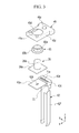
FIG. 3 illustrates an exploded perspective view of a part of the rechargeable battery according to the first exemplary embodiment. -
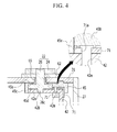
FIG. 4 illustrates a cross-sectional view of a part of the rechargeable battery according to the first exemplary embodiment. -
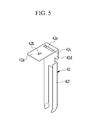
FIG. 5 illustrates a perspective view of a current collecting member according to the first exemplary embodiment. -
FIG. 6 illustrates a perspective view of a lower insulating member of the rechargeable battery, viewed from the bottom, according to the first exemplary embodiment. -
FIG. 7 illustrates a cross-sectional view of a part of a rechargeable battery according to a second exemplary embodiment. -
FIG. 8 illustrates a cross-sectional view of a part of a rechargeable battery according to a third exemplary embodiment. - Example embodiments will now be described more fully hereinafter with reference to the accompanying drawings; however, they may be embodied in different forms and should not be construed as limited to the embodiments set forth herein. Rather, these embodiments are provided so that this disclosure will be thorough and complete, and will fully convey exemplary implementations to those skilled in the art.
- In the drawing figures, the dimensions of layers and regions may be exaggerated for clarity of illustration. It will also be understood that when a layer or element is referred to as being "on" another layer or substrate, it can be directly on the other layer or substrate, or intervening layers may also be present. In addition, it will also be understood that when a layer is referred to as being "between" two layers, it can be the only layer between the two layers, or one or more intervening layers may also be present. Like reference numerals refer to like elements throughout.
-
FIG. 1 illustrates a perspective view of a rechargeable battery according to a first exemplary embodiment, andFIG. 2 illustrates a cross-sectional view ofFIG. 1 , taken along the line II-II. - Referring to
FIG. 1 andFIG. 2 , arechargeable battery 101 according to the first exemplary embodiment may include anelectrode assembly 10 wound by interposing aseparator 13 between anegative electrode 11 and apositive electrode 12, acase 27 in which theelectrode assembly 10 is stored, and acap assembly 30 combined, e.g., attached, to an opening of thecase 27. - The
rechargeable battery 101 according to the first exemplary embodiment is exemplarily illustrated as a prism-shaped lithium ion rechargeable battery. However, embodiments are not limited thereto, e.g., therechargeable battery 101 may be applied to various types of batteries such as a lithium polymer battery or a cylindrical battery and the like. - The negative electrode (first electrode) 11 and the positive electrode (second electrode) 12 include coated regions where an active material is coated on a current collector formed of a thin metal foil, and
uncoated regions uncoated region 11a is formed at one lateral end of thenegative electrode 11 along a length direction thereof, and the positiveuncoated region 12a is formed at the other lateral end of the positive electrode along a length direction thereof. Thenegative electrode 11 and thepositive electrode 12 are wound by interposing theseparator 13, which operates as an insulator, between them. However, embodiments are not limited thereto, and theelectrode assembly 10 may be formed in a layered structure in which the negative electrode and the positive electrode, respectively formed of a plurality of sheets, are layered by interposing the separator between them. Thecase 27 may be roughly formed in a shape of a cuboid, and the opening may be formed at one side. For example, thecase 27 may be made of metal, e.g., aluminum, stainless steel, and the like. - The
cap assembly 30 may include acap plate 31 covering the opening of thecase 27, afirst terminal 21 protruding out of thecap plate 31 and electrically connected to thenegative electrode 11, and asecond terminal 22 protruding out of thecap plate 31 and electrically connected to thepositive electrode 12. - The
cap plate 31 is formed in an elongated plate shape in one direction, and is combined to the opening of thecase 27. Thecap plate 31 may include asealing cap 38 provided in an electrolyte injection opening 32, and avent plate 39 provided in avent hole 34 and formed with anotch 39a which is set to be opened at a predetermined pressure. - The
first terminal 21 and thesecond terminal 22 are provided to protrude above thecap plate 31. Thefirst terminal 21 is electrically connected to thenegative electrode 11 through acurrent collecting member 41, and thesecond terminal 22 is electrically connected to thepositive electrode 12 through acurrent collecting member 42. However, embodiments are not limited thereto, and thefirst terminal 21 may be electrically connected to the positive electrode while thesecond terminal 22 may be electrically connected to the negative electrode. - The
first terminal 21 may include an externally exposedouter terminal 23, and a connectingterminal 25 which is disposed below theouter terminal 23 and bonded to thecurrent collecting member 41. Theouter terminal 23 may be formed in a plate shape, and theconnecting terminal 25 may penetrate theouter terminal 23 and is fixed thereto. Theconnecting terminal 25 penetrates thecap plate 31, so an upper part of theconnecting terminal 25 contacts theouter terminal 23 and is fixed thereto, and a lower part of the connectingterminal 25 is fixed to the current collectingmember 41 by welding. - A
gasket 55 for sealing is provided between the connectingterminal 25 and thecap plate 31 and is inserted in the hole which the connectingterminal 25 penetrates. A lowerinsulating member 43 is provided under an inner side of thecap plate 31 so as to insulate thefirst terminal 21 from the current collectingmember 41 at thecap plate 31. - A short-
circuit tab 53 is electrically connected to thefirst terminal 21, and is disposed on thecap plate 31. An upperinsulating member 54 is provided between the short-circuit tab 53 and thecap plate 31 for electrical insulation. Theouter terminal 23 is disposed at one side of the short-circuit tab 53, and a protectingcover 56 is provided at the other side of the short-circuit tab 53. - The
second terminal 22 may include an externally exposedouter terminal 24 and a connectingterminal 26. Theouter terminal 24 may be formed in a plate shape, and theconnecting terminal 26 may penetrate theouter terminal 24 and is fixed thereto. - As shown in
FIG. 3 andFIG. 4 , theconnecting terminal 26 may include acolumn portion 26b penetrating thecap plate 31, such that thecolumn portion 26b contacts theouter terminal 24 and is fixed thereto, and alower flange 26a protruding outwardly from a lower part of thecolumn portion 26b. Alower protrusion 26c protrudes from a bottom side of thelower flange 26a downwardly, and is inserted in the current collectingmember 42 to be affixed thereto by welding. - A
gasket 65 for sealing is provided between the connectingterminal 26 and thecap plate 31 and is inserted in the hole which the connectingterminal 26 penetrates, and a lowerinsulating member 45 is provided under an inner side of thecap plate 31 so as to insulate thesecond terminal 22 from thecurrent collecting member 42 at thecap plate 31. As illustrated inFIG. 3 , thegasket 65 may include an upper insulatingportion 65b, which encloses thecolumn portion 26b, and a lower insulatingportion 65a, which contacts a top side of thelower flange 26a. - As shown in
FIGS. 3 and5 , the current collectingmember 42 may include an upper connectingportion 42a, which is bonded by welding to thelower flange 26a, a lower connectingportion 42d, which is bent from the upper connectingportion 42a and extended downwardly, and acurrent collecting protrusion 42f, which is bent from the lower connectingportion 42d and is fixed to the positive electrodeuncoated region 12a. The upper connectingportion 42a is formed with awelding hole 42b, in which thelower protrusion 26c formed at a lower part of thelower flange 26a is inserted. Thelower protrusion 26c is fixed by welding to the upper connectingportion 42a after being inserted in thewelding hole 42b. - The upper connecting
portion 42a is formed with afuse portion 42c, which has a smaller cross-sectional area than a periphery area. That is, afuse hole 42e is formed in the current collectingmember 42, and thefuse portion 42c is connected and formed at both lateral ends of thefuse hole 42e. Accordingly, the fuse portion 41c has a smaller cross-sectional area than the periphery area. However, embodiments are not limited thereto, and thefuse portion 42c may be formed with a groove and the like. - When an overcurrent flows through the current collecting
member 42, thefuse portion 42c in the current collectingmember 42 melts, thereby cutting off current through the current collectingmember 42. As a result, battery safety is improved. - According to example embodiments, the
fuse portion 42c is provided with a supportingmember 71 which encloses thefuse portion 42c, e.g., the supportingmember 71 may completely enclose thefuse portion 42c with the exception of thefuse hole 42e. The supportingmember 71 is provided on the current collectingmember 42 to enclose the periphery of thefuse portion 42c, e.g., to enclose a connecting part of the upper connectingportion 42a and the lower connectingportion 42d. - The supporting
member 71 may include anopening 71a connected with thefuse hole 42e. The supportingmember 71 is formed to block a lower part of thefuse hole 42e, and an upper part of thefuse hole 42e is opened through the opening 71 a. For example, as illustrated inFIG. 4 , the supportingmember 71 may include a first portion on, e.g., directly on, top surfaces of the upper connectingportion 42a and thefuse portion 42c, such that the opening 71 a and thefuse hole 42e overlap, e.g., completely overlap, each other. Further, the supportingmember 71 may include a second portion connected to the first portion and extending on lower surfaces of the upper connectingportion 42a and thefuse portion 42c, such that the second portion blocks, e.g., completely covers, a bottom of thefuse hole 42e. - The width of the second portion of the supporting
member 71 disposed on the lower part of thefuse portion 42c is thicker, e.g., along the z axis inFIG. 2 , than that of the first portion of the supportingmember 71 disposed on the upper part of thefuse portion 42c. The supportingmember 71 is created by insert injection molding, and is made of a polymer material. -
FIG. 6 illustrates a perspective view of the lower insulatingmember 45 viewed from the bottom. That is, the view of the lower insulatingmember 45 inFIG. 6 is inverted relative toFIG. 3 . - Referring to
FIGS. 3 and6 , the lower insulatingmember 45 may include anupper plate 45a, alateral side 45c protruding down from an end of theupper plate 45a and enclosing thelower flange 26a and the current collectingmember 42, and a steppedportion 45b protruding down from theupper plate 45a and disposed above the supportingmember 71. Theupper plate 45a is provided to cover a top side of thelower flange 26a, and the steppedportion 45b has a larger width than theupper plate 45a (along the y-axis inFIG. 3 ) and is disposed above the supportingmember 71. - The
upper plate 45a is formed with aterminal hole 45d, in which thecolumn portion 26a is inserted, and thegasket 65 is inserted into theterminal hole 45d along with thecolumn portion 26b. A spacer (barrier) 45e is formed protruding toward the current collectingmember 42 in the steppedportion 45b, and is elongated in a ring shape. - The
spacer 45e serves to separate, i.e. to dispose apart, the lower insulatingmember 45 from the supportingmember 71, and a bottom side of the steppedportion 45b is separated from the supportingmember 71. As illustrated in the enlarged section ofFIG. 4 , thespacer 45e is formed to enclose the circumference of an upper space of thefuse hole 42e, and thefuse hole 42e is closed and sealed by thespacer 45e and the supportingmember 71 as a result. - According to embodiments, the supporting
member 71 is positioned on the current collectingmember 42. Since the current collectingmember 42 may exhibit lower rigidity due to thefuse hole 42e there through, the supportingmember 71 on the current collectingmember 42 may increase stability and rigidity of the current collectingmember 42, thereby preventing the current collectingmember 42 from being deformed or damaged due to external impact or the like. - Further, according to embodiments, the supporting
member 71 separates between the current collectingmember 42 and the electrolyte. That is, when an overcurrent flows through the current collectingmember 42 due to a short-circuit, overcharge, and the like, thefuse portion 42c melts, thereby generating a first arc. If arc residues melted by the arc generation drop down and contact an electrolyte solution, the possibility of fire is highly increased. However, as the supportingmember 71 separates between the current collectingmember 42 and the electrolyte, the supportingmember 71 prevent the arc residues from contacting the electrolyte solution. - Moreover, since the
fuse portion 42c and thefuse hole 42e are closed and sealed by the lower insulatingmember 45, air inflow is blocked, thereby decreasing or blocking arc generation. In particular, since thespacer 45e is formed at a connecting part of the lower insulatingmember 45 and the supportingmember 71, the lower insulatingmember 45 is separated from a heating source, such that it can be prevented from being melted by heat. As a result, even if a stronger secondary arc is generated after the first arc generation, oxygen deficiency prevents therechargeable battery 101 from catching fire. - According to a melting experiment of the
fuse portion 42c, the secondary arc which is created by the melting part, after thefuse portion 42c is completely melted, is larger than the first arc generated while thefuse portion 42c is being melted. Accordingly, when the secondary arc is generated, there is a greater risk of catching fire inside therechargeable battery 101. However, according to the present exemplary embodiment, even if the first arc is generated, since the lower insulatingmember 45 is not melted and thefuse portion 42c is closed by sealing, the rechargeable battery is prevented from catching fire or exploding when the secondary arc is generated due to oxygen deficiency. -
FIG. 7 illustrates a cross-sectional view of a part of a rechargeable battery according to a second exemplary embodiment. Since the rechargeable battery according to the present exemplary embodiment has the same structure as the rechargeable battery according to the first exemplary embodiment, except for the structure of a supportingmember 72 and a lower insulatingmember 75, a repeated description of the same structure is omitted. - Referring to
FIG. 7 , the supportingmember 72 according to the second exemplary embodiment is provided to enclose the periphery of thefuse portion 42c, such that it is installed at a connecting part of the upper connectingportion 42a and the lower connectingportion 42d. The supportingmember 72 is provided with anopening 72a overlapping an upper part of thefuse hole 42e, and is formed to block, e.g., overlap, a lower part of thefuse hole 42e. That is, the upper part of thefuse hole 42e is open through theopening 72a. - A width of the supporting
member 72 disposed at the lower part of thefuse portion 42c is greater than that of the supporting member disposed at the upper part of thefuse portion 42c. The supportingmember 72 may be created by insert injection molding, and is made of a polymer material. - The periphery of the
opening 72a is formed with a spacer (barrier) 72b protruding toward the lower insulatingmember 75. Thespacer 72b is formed in an elongated ring shape to enclose the circumference of theopening 72a, and protrudes upwards. Thespacer 72b serves to separate, i.e. to dispose apart, the lower insulatingmember 75 from the supportingmember 72, and is formed to enclose the circumference of the upper space of thefuse hole 42e. - The
fuse hole 42e is closed and sealed by the supportingmember 72 and the lower insulatingmember 75. The lower insulatingmember 75 insulates thecap plate 31 from the current collectingmember 42, and is provided to cover the lower flange and the supportingmember 72. The lower insulatingmember 75 contacts thespacer 72b so as to close and seal thefuse hole 42e, and is disposed apart from the supportingmember 72 by thespacer 72b. -
FIG. 8 illustrates a cross-sectional view of a part of a rechargeable battery according to a third exemplary embodiment. Since the rechargeable battery according to the third exemplary embodiment has the same structure as the rechargeable battery according to the first exemplary embodiment, except for the structure of a supportingmember 73 and a lower insulatingmember 76, a repeated description of the same structure is omitted. - The supporting
member 73 according to the third exemplary embodiment is provided to enclose the periphery of thefuse portion 42c at the current collectingmember 42, such that it is installed at the connecting part of the upper connectingportion 42a and the lower connectingportion 42d. The supportingmember 73 is formed with anopening 73a and is provided to block the lower part of thefuse hole 42e, and the upper part of thefuse hole 42e is opened through theopening 73a. - A width of the supporting
member 73 disposed at the lower part of thefuse portion 42c is greater than that of the supportingmember 73 disposed at the upper part of thefuse portion 42c. The supportingmember 73 may be created by insert injection molding, and is made of a polymer material. - The periphery of the
opening 73a is formed with afirst groove 73b into which a spacer (barrier) 78 is inserted, and thefirst groove 73b is elongated to enclose the circumference of theopening 73a. The lower part of thespacer 78 is formed to be inserted into thefirst groove 73b, and is elongated in a ring shape in a circumferential direction of theopening 73a. Thespacer 78 serves to separate the lower insulatingmember 76 from the supportingmember 73, and is formed to enclose the circumference of the upper space of thefuse hole 42e. - Accordingly, the
fuse hole 42e is closed and sealed by the supportingmember 73, the lower insulatingmember 76, and thespacer 78. The lower insulatingmember 76 separates thecap plate 31 from the current collectingmember 42, and is provided to cover thelower flange 26a and the supportingmember 73. The lower insulatingmember 76 is formed with asecond groove 76a into which thespacer 78 is inserted. Thesecond groove 76a is formed to be elongated in a circumferential direction of theopening 73a. - Accordingly, the lower part of the
spacer 78 is inserted into thefirst groove 73b, and the upper part of thespacer 78 inserted into thesecond groove 76a. The lower insulatingmember 76 contacts thespacer 78 and thereby closes and seals thefuse hole 42e, and is separated, i.e. disposed apart, from the supportingmember 73 by a middle part of thespacer 78. - According to an exemplary embodiment, a rechargeable battery, which can prevent members neighboring the fuse from being melted when the fuse is melted, provided. That is, a spacer is formed between a lower insulating member and a current collecting member, thereby blocking the lower insulating member from heat generated by melting of the fuse portion. Accordingly, the lower insulating member is prevented from melting when the fuse portion melts. Moreover, since the fuse hole is closed and sealed by a supporting member and the lower insulating member, ignition or explosion of the rechargeable battery may be prevented when a secondary arc is generated.
- In contrast, when an overcurrent flows due to a short circuit and the like through a conventional current collecting member, a fuse inside the rechargeable battery melts. However, due to high heat generated during the melting of the fuse, members adjacent to the melting fuse may melt as well. Further, a secondary arc may be generated between the melted members, thereby causing ignition or explosion of the rechargeable battery.
- Example embodiments have been disclosed herein, and although specific terms are employed, they are used and are to be interpreted in a generic and descriptive sense only and not for purpose of limitation. In some instances, as would be apparent to one of ordinary skill in the art as of the filing of the present application, features, characteristics, and/or elements described in connection with a particular embodiment may be used singly or in combination with features, characteristics, and/or elements described in connection with other embodiments unless otherwise specifically indicated. Accordingly, it will be understood by those of skill in the art that various changes in form and details may be made without departing from the scope of the present invention as set forth in the following claims.
Claims (12)
- A rechargeable battery (101), comprising:a case (27);an electrode assembly (10) including a first electrode (12) and a second electrode (11);a cap plate (31) a current collecting member (42) electrically connected to the first electrode (12), the current collecting member (42) including a fuse portion (42c);a lower insulating member (45, 75, 76), anda terminal (22) electrically connected to the current collecting member (42)wherein the electrode assembly (10), the current collecting member (42) and the lower insulating member (45, 76) are stored in the case (27) andwherein the cap plate (31) is attached to the case (27) such that the lower insulating member (45) is between the cap plate (31) and the current collecting member (42) with the terminal (22) protruding out of the cap plate (31); the rechargeable battery (101) further comprisinga spacer (45e, 72b, 78) between the lower insulating member (45, 75, 76) and the fuse portion (42c), the spacer (45e, 72b, 78) disposing apart from the fuse portion (42c) the lower insulating member.
- The rechargeable battery as claimed in claim 1, wherein the current collecting member (42) further comprises a fuse hole (42e), the spacer (45e, 72b, 78) extending in a circumferential direction of the fuse hole (42e).
- The rechargeable battery as claimed in claim 2, wherein the fuse portion (42c) is at two lateral ends of the fuse hole (42e).
- The rechargeable battery as claimed in claim 2 or 3, wherein the current collecting member (42) further comprises a supporting member (71, 72, 73), the supporting member (71, 72, 73) overlapping a lower part of the fuse hole (42e).
- The rechargeable battery as claimed in claim 4, wherein the supporting member (71, 72, 73) encloses the current collecting member (42), the supporting member (71, 72, 73) including an opening (71a, 72a, 73a) overlapping and in fluid communication with an upper part of the fuse hole (42e).
- The rechargeable battery as claimed in claim 5, wherein the current collecting member further comprises:an upper connecting portion (42a) bonded to the terminal (22); anda lower connecting portion (42d) bent at the upper connecting portion (42a) and extending downwardly from the upper connecting portion (42a), the supporting member (71, 72, 73) enclosing a connecting part of the upper connecting portion (42a) and the lower connecting portion (42d).
- The rechargeable battery as claimed in one of claims 4 to 6, wherein the spacer (72b) protrudes toward the lower insulating member (75) from the supporting member (72).
- The rechargeable battery as claimed in one of claims 4 to 6, wherein the spacer (45e) protrudes toward the current collecting member (42) from the lower insulating member (45).
- The rechargeable battery as claimed in claim 8, wherein the lower insulating member (45) includes:an upper plate (45a);a lateral side (45c) protruding from a lateral end of the upper plate (45a), the lateral side (45c) enclosing a lower flange portion (26a) of the terminal (22) and a portion of the current collecting member (42); anda stepped portion (45e) above the supporting member (71, 72, 73), the stepped portion (45e) protruding down from the upper plate (45a).
- The rechargeable battery as claimed in claim 9, wherein the spacer protrudes from the stepped portion (45e), the stepped portion (45e) being disposed apart from the supporting member (71, 72, 73).
- The rechargeable battery as claimed in one of claims 4 to 10, wherein the supporting member (73) includes a first groove (73b), the spacer (78) being inserted in the first groove (73b).
- The rechargeable battery as claimed in claim 11, wherein a lower part of the spacer (78) is inserted in the first groove (73b), and the lower insulating member (76) includes a second groove (76a) in which an upper part of the spacer (78) is inserted.
Applications Claiming Priority (1)
| Application Number | Priority Date | Filing Date | Title |
|---|---|---|---|
| KR1020130108590A KR101711993B1 (en) | 2013-09-10 | 2013-09-10 | Rechargeable battery having fuse |
Publications (2)
| Publication Number | Publication Date |
|---|---|
| EP2846378A1 true EP2846378A1 (en) | 2015-03-11 |
| EP2846378B1 EP2846378B1 (en) | 2017-05-10 |
Family
ID=50184835
Family Applications (1)
| Application Number | Title | Priority Date | Filing Date |
|---|---|---|---|
| EP14157409.5A Active EP2846378B1 (en) | 2013-09-10 | 2014-03-03 | Rechargeable battery having a fuse |
Country Status (3)
| Country | Link |
|---|---|
| US (1) | US9455479B2 (en) |
| EP (1) | EP2846378B1 (en) |
| KR (1) | KR101711993B1 (en) |
Cited By (3)
| Publication number | Priority date | Publication date | Assignee | Title |
|---|---|---|---|---|
| EP3512006A1 (en) * | 2018-01-16 | 2019-07-17 | Contemporary Amperex Technology Co., Limited | Connection member and rechargeable battery |
| EP3723153A1 (en) * | 2019-04-09 | 2020-10-14 | Contemporary Amperex Technology Co., Limited | Secondary battery and top cover component thereof |
| JP2023550814A (en) * | 2020-05-29 | 2023-12-05 | ヴァルタ マイクロバッテリー ゲゼルシャフト ミット ベシュレンクテル ハフツング | Energy storage element with prismatic housing |
Families Citing this family (3)
| Publication number | Priority date | Publication date | Assignee | Title |
|---|---|---|---|---|
| CN105428584B (en) * | 2014-09-11 | 2020-05-01 | 株式会社杰士汤浅国际 | Electric storage element |
| JP6597130B2 (en) * | 2015-09-29 | 2019-10-30 | 三洋電機株式会社 | Prismatic secondary battery |
| KR102203249B1 (en) * | 2017-10-10 | 2021-01-13 | 주식회사 엘지화학 | Cylindrical Battery Cell Having Connection Cap |
Citations (8)
| Publication number | Priority date | Publication date | Assignee | Title |
|---|---|---|---|---|
| EP2348559A1 (en) * | 2010-01-26 | 2011-07-27 | SB LiMotive Co., Ltd. | Rechargeable battery |
| EP2348558A1 (en) * | 2010-01-26 | 2011-07-27 | SB LiMotive Co., Ltd. | Rechargeable battery |
| EP2372808A1 (en) * | 2010-03-30 | 2011-10-05 | SB LiMotive Co., Ltd. | Secondary battery having a fuse |
| EP2393145A1 (en) * | 2010-06-04 | 2011-12-07 | SB LiMotive Co., Ltd. | Secondary battery |
| EP2506334A1 (en) * | 2011-03-30 | 2012-10-03 | SB LiMotive Co., Ltd. | Secondary battery |
| EP2544265A1 (en) * | 2011-07-06 | 2013-01-09 | SB LiMotive Co., Ltd. | Rechargeable battery |
| EP2787562A1 (en) * | 2013-04-01 | 2014-10-08 | Samsung SDI Co., Ltd. | Rechargeable secondary battery |
| EP2793293A1 (en) * | 2013-04-17 | 2014-10-22 | Samsung SDI Co., Ltd. | Rechargeable battery |
Family Cites Families (6)
| Publication number | Priority date | Publication date | Assignee | Title |
|---|---|---|---|---|
| TW432736B (en) * | 1999-02-23 | 2001-05-01 | Sanyo Electric Co | Pack battery |
| US7473487B2 (en) | 2001-06-05 | 2009-01-06 | Panasonic Corporation | Temperature fuse, and battery using the same |
| KR100420148B1 (en) | 2001-10-19 | 2004-03-02 | 삼성에스디아이 주식회사 | Protector and secondary battery mounting the such |
| US9099732B2 (en) | 2010-06-11 | 2015-08-04 | Samsung Sdi Co., Ltd. | Rechargeable battery having a fuse with an insulating blocking member |
| KR101274806B1 (en) | 2011-07-26 | 2013-06-13 | 로베르트 보쉬 게엠베하 | Rechargeable battery |
| KR101287087B1 (en) * | 2011-10-14 | 2013-07-17 | 로베르트 보쉬 게엠베하 | Rechargeable battery |
-
2013
- 2013-09-10 KR KR1020130108590A patent/KR101711993B1/en active Active
-
2014
- 2014-01-08 US US14/149,950 patent/US9455479B2/en active Active
- 2014-03-03 EP EP14157409.5A patent/EP2846378B1/en active Active
Patent Citations (8)
| Publication number | Priority date | Publication date | Assignee | Title |
|---|---|---|---|---|
| EP2348559A1 (en) * | 2010-01-26 | 2011-07-27 | SB LiMotive Co., Ltd. | Rechargeable battery |
| EP2348558A1 (en) * | 2010-01-26 | 2011-07-27 | SB LiMotive Co., Ltd. | Rechargeable battery |
| EP2372808A1 (en) * | 2010-03-30 | 2011-10-05 | SB LiMotive Co., Ltd. | Secondary battery having a fuse |
| EP2393145A1 (en) * | 2010-06-04 | 2011-12-07 | SB LiMotive Co., Ltd. | Secondary battery |
| EP2506334A1 (en) * | 2011-03-30 | 2012-10-03 | SB LiMotive Co., Ltd. | Secondary battery |
| EP2544265A1 (en) * | 2011-07-06 | 2013-01-09 | SB LiMotive Co., Ltd. | Rechargeable battery |
| EP2787562A1 (en) * | 2013-04-01 | 2014-10-08 | Samsung SDI Co., Ltd. | Rechargeable secondary battery |
| EP2793293A1 (en) * | 2013-04-17 | 2014-10-22 | Samsung SDI Co., Ltd. | Rechargeable battery |
Cited By (7)
| Publication number | Priority date | Publication date | Assignee | Title |
|---|---|---|---|---|
| EP3512006A1 (en) * | 2018-01-16 | 2019-07-17 | Contemporary Amperex Technology Co., Limited | Connection member and rechargeable battery |
| US10910622B2 (en) | 2018-01-16 | 2021-02-02 | Contemporary Amperex Technology Co., Limited | Connection member and rechargeable battery |
| EP3723153A1 (en) * | 2019-04-09 | 2020-10-14 | Contemporary Amperex Technology Co., Limited | Secondary battery and top cover component thereof |
| JP2022527733A (en) * | 2019-04-09 | 2022-06-06 | コンテンポラリー アンペレックス テクノロジー カンパニー リミテッド | Secondary battery and its top cover parts |
| JP7148741B2 (en) | 2019-04-09 | 2022-10-05 | コンテンポラリー アンペレックス テクノロジー カンパニー リミテッド | Secondary battery and its upper cover part |
| US12609382B2 (en) | 2019-04-09 | 2026-04-21 | Contemporary Amperex Technology (Hong Kong) Limited | Secondary battery and top cover component thereof |
| JP2023550814A (en) * | 2020-05-29 | 2023-12-05 | ヴァルタ マイクロバッテリー ゲゼルシャフト ミット ベシュレンクテル ハフツング | Energy storage element with prismatic housing |
Also Published As
| Publication number | Publication date |
|---|---|
| KR101711993B1 (en) | 2017-03-03 |
| KR20150029413A (en) | 2015-03-18 |
| US20150072186A1 (en) | 2015-03-12 |
| EP2846378B1 (en) | 2017-05-10 |
| US9455479B2 (en) | 2016-09-27 |
Similar Documents
| Publication | Publication Date | Title |
|---|---|---|
| EP2348558B1 (en) | Rechargeable battery | |
| US9059459B2 (en) | Secondary battery | |
| JP6491817B2 (en) | Secondary battery | |
| EP2348559B1 (en) | Rechargeable battery | |
| KR102632924B1 (en) | Secondary Battery | |
| EP3518305B1 (en) | Secondary battery | |
| JP6491448B2 (en) | Secondary battery and battery module | |
| JP6441598B2 (en) | Secondary battery | |
| EP2854201B1 (en) | Rechargeable battery | |
| KR101772415B1 (en) | Cap assembly and secondary battery including the same | |
| KR101744090B1 (en) | Rechargeable battery having short member | |
| EP2793295A2 (en) | Rechargeable battery | |
| KR102080903B1 (en) | Electrode lead and secondary battery including the same | |
| KR102371193B1 (en) | Secondary Battery | |
| EP2846378B1 (en) | Rechargeable battery having a fuse | |
| US10930986B2 (en) | Rechargeable battery | |
| US10522813B2 (en) | Secondary battery | |
| US20150024241A1 (en) | Rechargeable battery | |
| US9431646B2 (en) | Rechargeable battery having connection member | |
| US12476338B2 (en) | Secondary battery | |
| KR101563680B1 (en) | Secondary battery | |
| EP4290673A1 (en) | Secondary battery | |
| KR20060037834A (en) | Secondary battery |
Legal Events
| Date | Code | Title | Description |
|---|---|---|---|
| 17P | Request for examination filed |
Effective date: 20140303 |
|
| AK | Designated contracting states |
Kind code of ref document: A1 Designated state(s): AL AT BE BG CH CY CZ DE DK EE ES FI FR GB GR HR HU IE IS IT LI LT LU LV MC MK MT NL NO PL PT RO RS SE SI SK SM TR |
|
| AX | Request for extension of the european patent |
Extension state: BA ME |
|
| PUAI | Public reference made under article 153(3) epc to a published international application that has entered the european phase |
Free format text: ORIGINAL CODE: 0009012 |
|
| R17P | Request for examination filed (corrected) |
Effective date: 20150909 |
|
| RBV | Designated contracting states (corrected) |
Designated state(s): AL AT BE BG CH CY CZ DE DK EE ES FI FR GB GR HR HU IE IS IT LI LT LU LV MC MK MT NL NO PL PT RO RS SE SI SK SM TR |
|
| GRAP | Despatch of communication of intention to grant a patent |
Free format text: ORIGINAL CODE: EPIDOSNIGR1 |
|
| STAA | Information on the status of an ep patent application or granted ep patent |
Free format text: STATUS: GRANT OF PATENT IS INTENDED |
|
| RIC1 | Information provided on ipc code assigned before grant |
Ipc: H01M 10/058 20100101ALN20161115BHEP Ipc: H01M 2/26 20060101AFI20161115BHEP Ipc: H01M 10/04 20060101ALI20161115BHEP Ipc: H01M 2/34 20060101ALI20161115BHEP |
|
| INTG | Intention to grant announced |
Effective date: 20161207 |
|
| RIC1 | Information provided on ipc code assigned before grant |
Ipc: H01M 10/04 20060101ALI20161128BHEP Ipc: H01M 2/26 20060101AFI20161128BHEP Ipc: H01M 10/058 20100101ALN20161128BHEP Ipc: H01M 2/34 20060101ALI20161128BHEP |
|
| GRAS | Grant fee paid |
Free format text: ORIGINAL CODE: EPIDOSNIGR3 |
|
| GRAA | (expected) grant |
Free format text: ORIGINAL CODE: 0009210 |
|
| STAA | Information on the status of an ep patent application or granted ep patent |
Free format text: STATUS: THE PATENT HAS BEEN GRANTED |
|
| AK | Designated contracting states |
Kind code of ref document: B1 Designated state(s): AL AT BE BG CH CY CZ DE DK EE ES FI FR GB GR HR HU IE IS IT LI LT LU LV MC MK MT NL NO PL PT RO RS SE SI SK SM TR |
|
| REG | Reference to a national code |
Ref country code: GB Ref legal event code: FG4D |
|
| REG | Reference to a national code |
Ref country code: AT Ref legal event code: REF Ref document number: 893175 Country of ref document: AT Kind code of ref document: T Effective date: 20170515 Ref country code: CH Ref legal event code: EP |
|
| REG | Reference to a national code |
Ref country code: IE Ref legal event code: FG4D |
|
| REG | Reference to a national code |
Ref country code: DE Ref legal event code: R096 Ref document number: 602014009548 Country of ref document: DE |
|
| REG | Reference to a national code |
Ref country code: NL Ref legal event code: MP Effective date: 20170510 |
|
| REG | Reference to a national code |
Ref country code: LT Ref legal event code: MG4D |
|
| REG | Reference to a national code |
Ref country code: AT Ref legal event code: MK05 Ref document number: 893175 Country of ref document: AT Kind code of ref document: T Effective date: 20170510 |
|
| PG25 | Lapsed in a contracting state [announced via postgrant information from national office to epo] |
Ref country code: AT Free format text: LAPSE BECAUSE OF FAILURE TO SUBMIT A TRANSLATION OF THE DESCRIPTION OR TO PAY THE FEE WITHIN THE PRESCRIBED TIME-LIMIT Effective date: 20170510 Ref country code: GR Free format text: LAPSE BECAUSE OF FAILURE TO SUBMIT A TRANSLATION OF THE DESCRIPTION OR TO PAY THE FEE WITHIN THE PRESCRIBED TIME-LIMIT Effective date: 20170811 Ref country code: ES Free format text: LAPSE BECAUSE OF FAILURE TO SUBMIT A TRANSLATION OF THE DESCRIPTION OR TO PAY THE FEE WITHIN THE PRESCRIBED TIME-LIMIT Effective date: 20170510 Ref country code: LT Free format text: LAPSE BECAUSE OF FAILURE TO SUBMIT A TRANSLATION OF THE DESCRIPTION OR TO PAY THE FEE WITHIN THE PRESCRIBED TIME-LIMIT Effective date: 20170510 Ref country code: FI Free format text: LAPSE BECAUSE OF FAILURE TO SUBMIT A TRANSLATION OF THE DESCRIPTION OR TO PAY THE FEE WITHIN THE PRESCRIBED TIME-LIMIT Effective date: 20170510 Ref country code: NO Free format text: LAPSE BECAUSE OF FAILURE TO SUBMIT A TRANSLATION OF THE DESCRIPTION OR TO PAY THE FEE WITHIN THE PRESCRIBED TIME-LIMIT Effective date: 20170810 Ref country code: HR Free format text: LAPSE BECAUSE OF FAILURE TO SUBMIT A TRANSLATION OF THE DESCRIPTION OR TO PAY THE FEE WITHIN THE PRESCRIBED TIME-LIMIT Effective date: 20170510 |
|
| PG25 | Lapsed in a contracting state [announced via postgrant information from national office to epo] |
Ref country code: SE Free format text: LAPSE BECAUSE OF FAILURE TO SUBMIT A TRANSLATION OF THE DESCRIPTION OR TO PAY THE FEE WITHIN THE PRESCRIBED TIME-LIMIT Effective date: 20170510 Ref country code: PL Free format text: LAPSE BECAUSE OF FAILURE TO SUBMIT A TRANSLATION OF THE DESCRIPTION OR TO PAY THE FEE WITHIN THE PRESCRIBED TIME-LIMIT Effective date: 20170510 Ref country code: BG Free format text: LAPSE BECAUSE OF FAILURE TO SUBMIT A TRANSLATION OF THE DESCRIPTION OR TO PAY THE FEE WITHIN THE PRESCRIBED TIME-LIMIT Effective date: 20170810 Ref country code: NL Free format text: LAPSE BECAUSE OF FAILURE TO SUBMIT A TRANSLATION OF THE DESCRIPTION OR TO PAY THE FEE WITHIN THE PRESCRIBED TIME-LIMIT Effective date: 20170510 Ref country code: RS Free format text: LAPSE BECAUSE OF FAILURE TO SUBMIT A TRANSLATION OF THE DESCRIPTION OR TO PAY THE FEE WITHIN THE PRESCRIBED TIME-LIMIT Effective date: 20170510 Ref country code: LV Free format text: LAPSE BECAUSE OF FAILURE TO SUBMIT A TRANSLATION OF THE DESCRIPTION OR TO PAY THE FEE WITHIN THE PRESCRIBED TIME-LIMIT Effective date: 20170510 Ref country code: IS Free format text: LAPSE BECAUSE OF FAILURE TO SUBMIT A TRANSLATION OF THE DESCRIPTION OR TO PAY THE FEE WITHIN THE PRESCRIBED TIME-LIMIT Effective date: 20170910 |
|
| PG25 | Lapsed in a contracting state [announced via postgrant information from national office to epo] |
Ref country code: DK Free format text: LAPSE BECAUSE OF FAILURE TO SUBMIT A TRANSLATION OF THE DESCRIPTION OR TO PAY THE FEE WITHIN THE PRESCRIBED TIME-LIMIT Effective date: 20170510 Ref country code: CZ Free format text: LAPSE BECAUSE OF FAILURE TO SUBMIT A TRANSLATION OF THE DESCRIPTION OR TO PAY THE FEE WITHIN THE PRESCRIBED TIME-LIMIT Effective date: 20170510 Ref country code: EE Free format text: LAPSE BECAUSE OF FAILURE TO SUBMIT A TRANSLATION OF THE DESCRIPTION OR TO PAY THE FEE WITHIN THE PRESCRIBED TIME-LIMIT Effective date: 20170510 Ref country code: SK Free format text: LAPSE BECAUSE OF FAILURE TO SUBMIT A TRANSLATION OF THE DESCRIPTION OR TO PAY THE FEE WITHIN THE PRESCRIBED TIME-LIMIT Effective date: 20170510 Ref country code: RO Free format text: LAPSE BECAUSE OF FAILURE TO SUBMIT A TRANSLATION OF THE DESCRIPTION OR TO PAY THE FEE WITHIN THE PRESCRIBED TIME-LIMIT Effective date: 20170510 |
|
| REG | Reference to a national code |
Ref country code: DE Ref legal event code: R097 Ref document number: 602014009548 Country of ref document: DE |
|
| REG | Reference to a national code |
Ref country code: FR Ref legal event code: PLFP Year of fee payment: 5 |
|
| PG25 | Lapsed in a contracting state [announced via postgrant information from national office to epo] |
Ref country code: IT Free format text: LAPSE BECAUSE OF FAILURE TO SUBMIT A TRANSLATION OF THE DESCRIPTION OR TO PAY THE FEE WITHIN THE PRESCRIBED TIME-LIMIT Effective date: 20170510 Ref country code: SM Free format text: LAPSE BECAUSE OF FAILURE TO SUBMIT A TRANSLATION OF THE DESCRIPTION OR TO PAY THE FEE WITHIN THE PRESCRIBED TIME-LIMIT Effective date: 20170510 |
|
| PLBE | No opposition filed within time limit |
Free format text: ORIGINAL CODE: 0009261 |
|
| STAA | Information on the status of an ep patent application or granted ep patent |
Free format text: STATUS: NO OPPOSITION FILED WITHIN TIME LIMIT |
|
| 26N | No opposition filed |
Effective date: 20180213 |
|
| PG25 | Lapsed in a contracting state [announced via postgrant information from national office to epo] |
Ref country code: SI Free format text: LAPSE BECAUSE OF FAILURE TO SUBMIT A TRANSLATION OF THE DESCRIPTION OR TO PAY THE FEE WITHIN THE PRESCRIBED TIME-LIMIT Effective date: 20170510 |
|
| REG | Reference to a national code |
Ref country code: CH Ref legal event code: PL |
|
| PG25 | Lapsed in a contracting state [announced via postgrant information from national office to epo] |
Ref country code: MC Free format text: LAPSE BECAUSE OF FAILURE TO SUBMIT A TRANSLATION OF THE DESCRIPTION OR TO PAY THE FEE WITHIN THE PRESCRIBED TIME-LIMIT Effective date: 20170510 |
|
| REG | Reference to a national code |
Ref country code: BE Ref legal event code: MM Effective date: 20180331 |
|
| REG | Reference to a national code |
Ref country code: IE Ref legal event code: MM4A |
|
| PG25 | Lapsed in a contracting state [announced via postgrant information from national office to epo] |
Ref country code: LU Free format text: LAPSE BECAUSE OF NON-PAYMENT OF DUE FEES Effective date: 20180303 |
|
| PG25 | Lapsed in a contracting state [announced via postgrant information from national office to epo] |
Ref country code: IE Free format text: LAPSE BECAUSE OF NON-PAYMENT OF DUE FEES Effective date: 20180303 |
|
| PG25 | Lapsed in a contracting state [announced via postgrant information from national office to epo] |
Ref country code: CH Free format text: LAPSE BECAUSE OF NON-PAYMENT OF DUE FEES Effective date: 20180331 Ref country code: BE Free format text: LAPSE BECAUSE OF NON-PAYMENT OF DUE FEES Effective date: 20180331 Ref country code: LI Free format text: LAPSE BECAUSE OF NON-PAYMENT OF DUE FEES Effective date: 20180331 |
|
| PG25 | Lapsed in a contracting state [announced via postgrant information from national office to epo] |
Ref country code: MT Free format text: LAPSE BECAUSE OF NON-PAYMENT OF DUE FEES Effective date: 20180303 |
|
| PG25 | Lapsed in a contracting state [announced via postgrant information from national office to epo] |
Ref country code: TR Free format text: LAPSE BECAUSE OF FAILURE TO SUBMIT A TRANSLATION OF THE DESCRIPTION OR TO PAY THE FEE WITHIN THE PRESCRIBED TIME-LIMIT Effective date: 20170510 |
|
| PG25 | Lapsed in a contracting state [announced via postgrant information from national office to epo] |
Ref country code: PT Free format text: LAPSE BECAUSE OF FAILURE TO SUBMIT A TRANSLATION OF THE DESCRIPTION OR TO PAY THE FEE WITHIN THE PRESCRIBED TIME-LIMIT Effective date: 20170510 |
|
| PG25 | Lapsed in a contracting state [announced via postgrant information from national office to epo] |
Ref country code: MK Free format text: LAPSE BECAUSE OF NON-PAYMENT OF DUE FEES Effective date: 20170510 Ref country code: CY Free format text: LAPSE BECAUSE OF FAILURE TO SUBMIT A TRANSLATION OF THE DESCRIPTION OR TO PAY THE FEE WITHIN THE PRESCRIBED TIME-LIMIT Effective date: 20170510 Ref country code: HU Free format text: LAPSE BECAUSE OF FAILURE TO SUBMIT A TRANSLATION OF THE DESCRIPTION OR TO PAY THE FEE WITHIN THE PRESCRIBED TIME-LIMIT; INVALID AB INITIO Effective date: 20140303 |
|
| PG25 | Lapsed in a contracting state [announced via postgrant information from national office to epo] |
Ref country code: AL Free format text: LAPSE BECAUSE OF FAILURE TO SUBMIT A TRANSLATION OF THE DESCRIPTION OR TO PAY THE FEE WITHIN THE PRESCRIBED TIME-LIMIT Effective date: 20170510 |
|
| REG | Reference to a national code |
Ref country code: DE Ref legal event code: R079 Ref document number: 602014009548 Country of ref document: DE Free format text: PREVIOUS MAIN CLASS: H01M0002260000 Ipc: H01M0050531000 |
|
| P01 | Opt-out of the competence of the unified patent court (upc) registered |
Effective date: 20230528 |
|
| PGFP | Annual fee paid to national office [announced via postgrant information from national office to epo] |
Ref country code: GB Payment date: 20260303 Year of fee payment: 13 |
|
| PGFP | Annual fee paid to national office [announced via postgrant information from national office to epo] |
Ref country code: DE Payment date: 20260305 Year of fee payment: 13 |
|
| PGFP | Annual fee paid to national office [announced via postgrant information from national office to epo] |
Ref country code: FR Payment date: 20260309 Year of fee payment: 13 |