EP2793293A1 - Rechargeable battery - Google Patents
Rechargeable battery Download PDFInfo
- Publication number
- EP2793293A1 EP2793293A1 EP20130188622 EP13188622A EP2793293A1 EP 2793293 A1 EP2793293 A1 EP 2793293A1 EP 20130188622 EP20130188622 EP 20130188622 EP 13188622 A EP13188622 A EP 13188622A EP 2793293 A1 EP2793293 A1 EP 2793293A1
- Authority
- EP
- European Patent Office
- Prior art keywords
- fuse
- current collecting
- rechargeable battery
- insulating
- insulating member
- Prior art date
- Legal status (The legal status is an assumption and is not a legal conclusion. Google has not performed a legal analysis and makes no representation as to the accuracy of the status listed.)
- Granted
Links
- 229920001774 Perfluoroether Polymers 0.000 claims description 6
- 239000004696 Poly ether ether ketone Substances 0.000 claims description 6
- 239000004734 Polyphenylene sulfide Substances 0.000 claims description 6
- 239000004743 Polypropylene Substances 0.000 claims description 6
- 229920002530 polyetherether ketone Polymers 0.000 claims description 6
- 229920000069 polyphenylene sulfide Polymers 0.000 claims description 6
- 229920001155 polypropylene Polymers 0.000 claims description 6
- 238000002347 injection Methods 0.000 claims description 5
- 239000007924 injection Substances 0.000 claims description 5
- 238000000926 separation method Methods 0.000 claims description 5
- -1 polypropylene Polymers 0.000 claims description 3
- 230000000712 assembly Effects 0.000 description 9
- 238000000429 assembly Methods 0.000 description 9
- 238000003466 welding Methods 0.000 description 8
- 239000008151 electrolyte solution Substances 0.000 description 5
- 239000000463 material Substances 0.000 description 5
- 239000011149 active material Substances 0.000 description 4
- 229910052751 metal Inorganic materials 0.000 description 4
- 239000002184 metal Substances 0.000 description 4
- 238000007789 sealing Methods 0.000 description 4
- 238000004880 explosion Methods 0.000 description 3
- 238000002485 combustion reaction Methods 0.000 description 2
- 230000003111 delayed effect Effects 0.000 description 2
- 239000003792 electrolyte Substances 0.000 description 2
- 239000011888 foil Substances 0.000 description 2
- 238000002844 melting Methods 0.000 description 2
- 230000008018 melting Effects 0.000 description 2
- 230000000149 penetrating effect Effects 0.000 description 2
- 239000010409 thin film Substances 0.000 description 2
- RYGMFSIKBFXOCR-UHFFFAOYSA-N Copper Chemical compound [Cu] RYGMFSIKBFXOCR-UHFFFAOYSA-N 0.000 description 1
- WHXSMMKQMYFTQS-UHFFFAOYSA-N Lithium Chemical compound [Li] WHXSMMKQMYFTQS-UHFFFAOYSA-N 0.000 description 1
- HBBGRARXTFLTSG-UHFFFAOYSA-N Lithium ion Chemical compound [Li+] HBBGRARXTFLTSG-UHFFFAOYSA-N 0.000 description 1
- 229910052782 aluminium Inorganic materials 0.000 description 1
- XAGFODPZIPBFFR-UHFFFAOYSA-N aluminium Chemical compound [Al] XAGFODPZIPBFFR-UHFFFAOYSA-N 0.000 description 1
- 230000000903 blocking effect Effects 0.000 description 1
- 229910052802 copper Inorganic materials 0.000 description 1
- 239000010949 copper Substances 0.000 description 1
- 238000000354 decomposition reaction Methods 0.000 description 1
- 230000003247 decreasing effect Effects 0.000 description 1
- 238000005516 engineering process Methods 0.000 description 1
- 239000012212 insulator Substances 0.000 description 1
- 229910052744 lithium Inorganic materials 0.000 description 1
- 229910001416 lithium ion Inorganic materials 0.000 description 1
- 238000000034 method Methods 0.000 description 1
- 239000011255 nonaqueous electrolyte Substances 0.000 description 1
- 229920000642 polymer Polymers 0.000 description 1
Images


Classifications
-
- H—ELECTRICITY
- H01—ELECTRIC ELEMENTS
- H01M—PROCESSES OR MEANS, e.g. BATTERIES, FOR THE DIRECT CONVERSION OF CHEMICAL ENERGY INTO ELECTRICAL ENERGY
- H01M50/00—Constructional details or processes of manufacture of the non-active parts of electrochemical cells other than fuel cells, e.g. hybrid cells
- H01M50/50—Current conducting connections for cells or batteries
- H01M50/572—Means for preventing undesired use or discharge
- H01M50/574—Devices or arrangements for the interruption of current
- H01M50/581—Devices or arrangements for the interruption of current in response to temperature
-
- H—ELECTRICITY
- H01—ELECTRIC ELEMENTS
- H01M—PROCESSES OR MEANS, e.g. BATTERIES, FOR THE DIRECT CONVERSION OF CHEMICAL ENERGY INTO ELECTRICAL ENERGY
- H01M10/00—Secondary cells; Manufacture thereof
- H01M10/04—Construction or manufacture in general
- H01M10/0413—Large-sized flat cells or batteries for motive or stationary systems with plate-like electrodes
-
- H—ELECTRICITY
- H01—ELECTRIC ELEMENTS
- H01M—PROCESSES OR MEANS, e.g. BATTERIES, FOR THE DIRECT CONVERSION OF CHEMICAL ENERGY INTO ELECTRICAL ENERGY
- H01M10/00—Secondary cells; Manufacture thereof
- H01M10/05—Accumulators with non-aqueous electrolyte
- H01M10/058—Construction or manufacture
-
- H—ELECTRICITY
- H01—ELECTRIC ELEMENTS
- H01M—PROCESSES OR MEANS, e.g. BATTERIES, FOR THE DIRECT CONVERSION OF CHEMICAL ENERGY INTO ELECTRICAL ENERGY
- H01M50/00—Constructional details or processes of manufacture of the non-active parts of electrochemical cells other than fuel cells, e.g. hybrid cells
- H01M50/50—Current conducting connections for cells or batteries
- H01M50/531—Electrode connections inside a battery casing
-
- H—ELECTRICITY
- H01—ELECTRIC ELEMENTS
- H01M—PROCESSES OR MEANS, e.g. BATTERIES, FOR THE DIRECT CONVERSION OF CHEMICAL ENERGY INTO ELECTRICAL ENERGY
- H01M50/00—Constructional details or processes of manufacture of the non-active parts of electrochemical cells other than fuel cells, e.g. hybrid cells
- H01M50/50—Current conducting connections for cells or batteries
- H01M50/572—Means for preventing undesired use or discharge
- H01M50/574—Devices or arrangements for the interruption of current
- H01M50/583—Devices or arrangements for the interruption of current in response to current, e.g. fuses
-
- H—ELECTRICITY
- H01—ELECTRIC ELEMENTS
- H01M—PROCESSES OR MEANS, e.g. BATTERIES, FOR THE DIRECT CONVERSION OF CHEMICAL ENERGY INTO ELECTRICAL ENERGY
- H01M2200/00—Safety devices for primary or secondary batteries
- H01M2200/10—Temperature sensitive devices
- H01M2200/103—Fuse
-
- H—ELECTRICITY
- H01—ELECTRIC ELEMENTS
- H01M—PROCESSES OR MEANS, e.g. BATTERIES, FOR THE DIRECT CONVERSION OF CHEMICAL ENERGY INTO ELECTRICAL ENERGY
- H01M50/00—Constructional details or processes of manufacture of the non-active parts of electrochemical cells other than fuel cells, e.g. hybrid cells
- H01M50/50—Current conducting connections for cells or batteries
- H01M50/531—Electrode connections inside a battery casing
- H01M50/536—Electrode connections inside a battery casing characterised by the method of fixing the leads to the electrodes, e.g. by welding
-
- H—ELECTRICITY
- H01—ELECTRIC ELEMENTS
- H01M—PROCESSES OR MEANS, e.g. BATTERIES, FOR THE DIRECT CONVERSION OF CHEMICAL ENERGY INTO ELECTRICAL ENERGY
- H01M50/00—Constructional details or processes of manufacture of the non-active parts of electrochemical cells other than fuel cells, e.g. hybrid cells
- H01M50/50—Current conducting connections for cells or batteries
- H01M50/531—Electrode connections inside a battery casing
- H01M50/538—Connection of several leads or tabs of wound or folded electrode stacks
-
- Y—GENERAL TAGGING OF NEW TECHNOLOGICAL DEVELOPMENTS; GENERAL TAGGING OF CROSS-SECTIONAL TECHNOLOGIES SPANNING OVER SEVERAL SECTIONS OF THE IPC; TECHNICAL SUBJECTS COVERED BY FORMER USPC CROSS-REFERENCE ART COLLECTIONS [XRACs] AND DIGESTS
- Y02—TECHNOLOGIES OR APPLICATIONS FOR MITIGATION OR ADAPTATION AGAINST CLIMATE CHANGE
- Y02E—REDUCTION OF GREENHOUSE GAS [GHG] EMISSIONS, RELATED TO ENERGY GENERATION, TRANSMISSION OR DISTRIBUTION
- Y02E60/00—Enabling technologies; Technologies with a potential or indirect contribution to GHG emissions mitigation
- Y02E60/10—Energy storage using batteries
-
- Y—GENERAL TAGGING OF NEW TECHNOLOGICAL DEVELOPMENTS; GENERAL TAGGING OF CROSS-SECTIONAL TECHNOLOGIES SPANNING OVER SEVERAL SECTIONS OF THE IPC; TECHNICAL SUBJECTS COVERED BY FORMER USPC CROSS-REFERENCE ART COLLECTIONS [XRACs] AND DIGESTS
- Y02—TECHNOLOGIES OR APPLICATIONS FOR MITIGATION OR ADAPTATION AGAINST CLIMATE CHANGE
- Y02P—CLIMATE CHANGE MITIGATION TECHNOLOGIES IN THE PRODUCTION OR PROCESSING OF GOODS
- Y02P70/00—Climate change mitigation technologies in the production process for final industrial or consumer products
- Y02P70/50—Manufacturing or production processes characterised by the final manufactured product
Definitions
- aspects of embodiments of the present invention relate to a rechargeable battery.
- a rechargeable battery is a battery that can be charged and discharged, unlike a primary battery that is incapable of being recharged.
- a rechargeable battery having low capacity may be used in a portable small electronic device, such as a mobile phone, a laptop computer, and a camcorder, and a battery having large capacity is widely used as a power source for driving a motor of a hybrid vehicle, an electric vehicle, and the like.
- the high-power rechargeable battery that uses a non-aqueous electrolyte having high energy density has been developed, and the high-power rechargeable battery is constituted by a large-capacity rechargeable battery in which a plurality of rechargeable batteries are coupled in series in order to be used for driving devices requiring large power, such as motors for electric vehicles, for example.
- a large-capacity rechargeable battery generally includes a plurality of rechargeable batteries that are coupled in series, and the rechargeable battery may be formed in cylindrical or angular shapes, for example.
- a rechargeable battery has improved safety.
- a structure of a safety apparatus that is capable of decreasing a risk when an overcurrent occurs is improved.
- a rechargeable battery includes: an electrode assembly including a negative electrode and a positive electrode; a case receiving the electrode assembly; a terminal electrically connected to the electrode assembly and protruding outside the case; a current collecting member electrically connecting the terminal and the electrode assembly to each other; and an insulating member partially enclosing the current collecting member, and the current collecting member includes a plurality of fuse parts including a first fuse part enclosed by the insulating member, and a second fuse part that is not enclosed by the insulating member and is exposed.
- a fuse hole may be formed in the current collecting member, the first fuse part may be adjacent one end of the fuse hole, and the second fuse part may be adjacent an opposite end of the fuse hole.
- the current collecting member may include a terminal combination part fixed to the terminal, a side plate bent from the terminal combination part, and a first current collecting piece bent from the side plate and fixed to the positive electrode or the negative electrode.
- the current collecting member may include a connection part connected to the side plate, and a second current collecting piece bent from the connection part and fixed to the positive electrode or the negative electrode.
- the insulating member may include a lower insulating part enclosing the connection part, and a current collecting insulating part enclosing the second current collecting piece bent from the connection part.
- the insulating member may include an upper insulating part enclosing the terminal combination part, and the upper insulating part may include a cut part exposing the second fuse part.
- the current collecting member may include a fuse hole, and the upper insulating part may include a separation supporting part inserted into the fuse hole.
- the insulating member may include a side insulating part enclosing the side plate, and a current collecting insulating part enclosing the first current collecting piece bent from the side plate.
- the first fuse part and the second fuse part may be separated and disposed according to a width direction of the insulating member.
- the current collecting member may include a first fuse hole and a second fuse hole, and the first fuse hole and the second fuse hole may be separated and disposed according to a width direction of the current collecting member.
- the first fuse part may be adjacent an end of the first fuse hole
- the second fuse part may be adjacent an end of the second fuse hole
- the current collecting member may further comprise a third fuse part positioned between the first fuse hole and the second fuse hole.
- the insulating member may include a cut part exposing the first fuse part and the second fuse part.
- the insulating member may be formed by insert injection.
- the insulating member may include at least one selected from the group consisting of polypropylene (PP), perfluoroalkoxy (PFA), polyphenylene sulfide (PPS), and polyether ether ketone (PEEK).
- PP polypropylene
- PFA perfluoroalkoxy
- PPS polyphenylene sulfide
- PEEK polyether ether ketone
- the fuse when the fuse is operated due to an overcurrent, the fuse is sequentially disconnected such that the generation of an arc is reduced, thereby improving safety.
- FIG. 1 is a perspective view of a rechargeable battery according to an exemplary embodiment of the present invention.
- FIG. 2 is a cross-sectional view of the rechargeable battery of FIG. 1 , taken along the line II-II.
- FIG. 3 is a partial exploded perspective view of electrode assemblies and a current collecting member of the rechargeable battery of FIG. 1 , according to an exemplary embodiment of the present invention.
- FIG. 4 is a cross-sectional view taken along the line IV-IV of FIG. 3 .
- FIG. 5 is a partial perspective view of the current collecting member of FIG. 3 .
- FIG. 6 is a perspective view of an insulating member of the rechargeable battery of FIG. 1 , according to an exemplary embodiment of the present invention.
- FIG. 7 is a partial perspective view of a current collecting member and an insulating member according to another exemplary embodiment of the present invention.
- FIG. 8 is a partial perspective view of the current collecting member of FIG. 7 .
- FIG. 1 is a perspective view of a rechargeable battery according to an exemplary embodiment of the present invention
- FIG. 2 is a cross-sectional view of the rechargeable battery of FIG. 1 , taken along the line II-II.
- a rechargeable battery 101 includes an electrode assembly 10 wound with a separator 13 between a positive electrode 11 and a negative electrode 12, a case 31 in which the electrode assembly 10 is disposed, a cap plate 25 coupled to an opening of the case 31, and a positive electrode terminal 21 and a negative electrode terminal 22 penetrating the cap plate to be installed.
- the rechargeable battery 101 may be a rectangular lithium ion rechargeable battery.
- the present invention is not limited thereto, and aspects of the present invention can be applied to various types of batteries, such as a lithium polymer battery or a cylindrical battery.
- the positive electrode 11 includes a positive coated region that is an area where an active material is coated to a current collector that is formed of a thin film metal foil that is made of aluminum or the like, for example, and a positive uncoated region 11a that is an area not coated with the active material.
- the negative electrode 12 includes a negative coated region that is an area where an active material is coated to a current collector that is formed of a thin film metal foil that is made of copper or the like, for example, and a negative uncoated region 12a that is an area not coated with the active material.
- the positive electrode uncoated region 11a is formed at one end of the positive electrode 11 along a lengthwise direction of the electrode assembly 10, and the negative electrode uncoated region 12a is formed at the other end of the negative electrode 12 along the lengthwise direction of the electrode assembly 10.
- the separator 13, which is an insulator, is interposed between and wound together with the positive electrode 11 and the negative electrode 12.
- the present invention is not limited thereto, and the electrode assembly 10 may have a structure in which a plurality of positive electrodes and negative electrodes formed in a sheet shape are stacked with a separator interposed therebetween.
- the case 31, in one embodiment, has a generally cuboid shape, and an opening is formed at a side thereof.
- the cap plate 25 is coupled to the opening of the case 31 and may be made of a thin metal plate.
- the cap plate 25 is installed with the positive electrode terminal 21 which protrudes outwardly from the cap plate 25 and is electrically connected with the positive electrode 11, and the negative electrode terminal 22 which protrudes outwardly from the cap plate 25 and is electrically connected with the negative electrode 12.
- the cap plate 25 in one embodiment, has an electrolyte injection opening for injecting an electrolyte solution, and a seal stopper 23 for sealing the electrolyte injection opening is installed to the cap plate 25.
- the cap plate 25 includes a vent member 27 in which a notch 27a is formed such that the vent member 27 may be broken according to an internal pressure (e.g., a predetermined internal pressure).
- the positive electrode terminal 21 is formed penetrating the cap plate 25, and a lower gasket 26 for sealing is installed between the cap plate 25 and the positive electrode terminal 21.
- the positive electrode terminal 21 may have a circular cylinder shape on which a screw thread is formed at an external circumference thereof, and the positive electrode terminal 21 may include a nut 29 supporting the positive electrode terminal 21 at the upper side.
- a connection plate 32 is installed between the cap plate 25 and the nut 29 at the positive electrode terminal 21.
- connection plate 32 electrically connects the positive electrode terminal 21 and the cap plate 25. Accordingly, in one embodiment, the cap plate 25 and the case 31 are electrically connected to the positive electrode 11.
- a lower insulating member 36 supporting a current collecting member 51 and the positive electrode terminal 21 is installed under the cap plate 25.
- the positive electrode terminal 21 is electrically connected to the positive electrode uncoated region 11a via the current collecting member 51, and a terminal flange coupled to the current collecting member 51 may be formed under the positive electrode terminal 21.
- the negative electrode terminal 22 penetrates the cap plate 25 to be installed, and a lower gasket 26 for sealing is installed between the cap plate 25 and the negative electrode terminal 22.
- the negative electrode terminal 22 may have a circular cylinder shape on which a screw thread is formed at an external circumference thereof, and the negative electrode terminal 22 may include a nut 29 supporting the negative electrode terminal 22.
- an upper gasket 24 for sealing and insulating is installed between the cap plate 25 and the nut 29 at the negative electrode terminal 22.
- a lower insulating member 35 insulating and supporting a current collecting member 52 and the negative electrode terminal 22 is installed under the negative electrode terminal 22.
- the negative electrode terminal 22 is electrically connected to the negative uncoated region 12a via the current collecting member 52, and a terminal flange coupled to the current collecting member 52 may be formed at a lower end of the negative electrode terminal 22.
- FIG. 3 is a partial exploded perspective view of electrode assemblies 10 and the current collecting member 51 of the rechargeable battery 101, according to an exemplary embodiment of the present invention
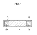
- FIG. 4 is a cross-sectional view taken along the line IV-IV of FIG. 3
- FIG. 5 is a partial perspective view of the current collecting member 51.
- the rechargeable battery 101 includes four electrode assemblies 10.
- the present invention is not limited thereto, and the rechargeable battery according to embodiments of the present invention may include one electrode assembly or any other suitable number of electrode assemblies.
- the current collecting member 51 includes a terminal combination part 512 fixed to the positive electrode terminal 21, a side plate 513 formed to be bent from the terminal combination part 512, current collecting pieces 517 and 518 fixed to the positive electrode uncoated regions 11a, and a first fuse part 515 and a second fuse part 514 formed at the terminal combination part 512.
- the current collecting member 52 installed at and coupled to the negative electrode terminal 22 may have a same structure as the current collecting member 51 installed at and coupled to the positive electrode terminal 21, and, therefore, description thereof is not repeated herein.
- the terminal combination part 512 in one embodiment, has a quadrangular plate-like shape, and has a supporting hole 512a in which the positive electrode terminal 21 is inserted at the center. Also, the terminal combination part 512 may be coupled under the positive electrode terminal 21 by welding.
- the side plate 513 is bent perpendicularly toward a bottom of the case 31 from the terminal combination part 512, thereby being disposed parallel to a side surface of the case 31. In other words, the side plate 513 is disposed parallel to a narrow surface of the case 31, on which the sign II is denoted in Fig. 1 .
- Two current collecting pieces 517 are connected to respective ends of the side plate 513 and are coupled to the positive electrode uncoated region 11a by welding, for example.
- a connection part 516 in one embodiment, is formed under the side plate 513, and two current collecting pieces 518 coupled to the positive electrode uncoated region 11a by welding, for example, are connected to respective ends of the connection part 516.
- the current collecting piece 517 is coupled to the positive electrode uncoated region 11a by welding in a state that the current collecting piece 517 is bent at both ends of the side plate 513 and is disposed parallel to the positive electrode uncoated region 11a.
- the current collecting piece 517 is coupled to the electrode assembly 10 that is disposed outside among the electrode assemblies 10.
- the current collecting piece 518 is coupled to the positive electrode uncoated region 11a by welding in a state that the current collecting piece 518 is bent at both end of the connection part 516 and is disposed parallel to the positive electrode uncoated region 11a.
- the current collecting piece 517 is coupled to the electrode assembly 10 that is positioned outside among the electrode assemblies 10, and the current collecting piece 518 is coupled to the electrode assembly 10 that is positioned inside among the electrode assemblies 10. In other words, the current collecting piece 517 is coupled to the outermost electrode assemblies 10 whereas the current collecting piece 518 is coupled to the innermost electrode assemblies 10.
- the terminal combination part 512 in one embodiment, includes a fuse hole 512b, and the fuse hole 512b is separated and disposed toward a side of the case 31 from the supporting hole 512a.
- the first fuse part 515 is formed to contact one end of the fuse hole 512b and the second fuse part 514 is formed to contact the other end of the fuse hole 512b.
- the first fuse part 515 and the second fuse part 514 in one embodiment, are disposed in line with each other along the width direction of the terminal combination part 512 and are separated by the fuse hole 512b.
- a sum of cross-sectional areas of the first fuse part 515 and the second fuse part 514 is smaller than a cross-sectional area of other portions of the current collecting member 51, such that the first fuse part 515 and the second fuse part 514 are melted to cut off the current when an overcurrent flows to the current collecting member 51.
- FIG. 6 is a perspective view of an insulating member of the rechargeable battery 101, according to an exemplary embodiment of the present invention.
- the current collecting member 51 includes an insulating member 61 for insulating and preventing or substantially preventing an arc, and, in one embodiment, the insulating member 61 is formed to partially enclose the current collecting member 51.
- the insulating member 61 in one embodiment, is installed to enclose the side plate 513 and the connection part 516 and a portion of the terminal combination part 512 and the current collecting pieces 517 and 518.
- the insulating member 61 in one embodiment, is formed by an insert injection method to enclose from the terminal combination part 512 to an upper portion of the current collecting pieces 517 and 518.
- the insulating member 61 in one embodiment, may be formed of polypropylene (PP), perfluoroalkoxy (PFA), polyphenylene sulfide (PPS), and polyether ether ketone (PEEK), for example.
- PP polypropylene
- PFA perfluoroalkoxy
- PPS polyphenylene sulfide
- PEEK polyether ether ketone
- the insulating member 61 is coated with a thin thickness to the surface of the current collecting member 51 to prevent or substantially prevent the current collecting member 51 from contacting the case 31 and to block an arc generated in the current collecting member 51 from contacting the electrolyte solution. If the arc generated in the current collecting member 51 contacts the electrolyte solution, the electrolyte solution may combust or explode because of high heat.
- the insulating member 61 in one embodiment, includes an upper insulating part 612 enclosing the terminal combination part 512, a side insulating part 615 enclosing the side plate 513, a lower insulating part 616 enclosing the connection part 516, and a plurality of current collecting insulating parts 617 and 618 enclosing upper portions of the current collecting pieces 517 and 518.
- the insulating member 61 has an inner space 619 to insert or accommodate the current collecting member 51.
- the side insulating part 615 is bent with respect to the upper insulating part 612 and is connected at the lower side of the upper insulating part 612, and the lower insulating part 616 is positioned under the side insulating part 615.
- the current collecting insulating part 617 is curved at the side insulating part 615
- the current collecting insulating part 618 is curved at the lower insulating part 616.
- the upper insulating part 612 includes a cut part 613, formed as a cutout in the insulating part 612 as shown in Fig 3 , and the cut part 613 exposes the second fuse part 514.
- the first fuse part 515 is enclosed by the insulating member 61, and the second fuse part 514 is exposed through the cut part 613.
- the insulating member 61 has a separation supporting part 614 inserted into the fuse hole 512b.
- the separation supporting part 614 is inserted into the fuse hole 512b such that the melted portions do not contact each other and maintain the separated state when the first and second fuse parts 515, 514 are melted.
- the separation supporting part 614 may be a protrusion inserted into the fuse hole 512b.
- the first fuse part 515 is covered by the insulating member 61, and the second fuse part 514 is exposed, and the second fuse part 514 is melted before the first fuse part 515. Also, the first fuse part 515 is melted when a time has passed after the second fuse part 514 is melted. This is because the heat is dissipated in the case of the first fuse part 515 enclosed by the insulating member 61.
- the insulating member 61 transmits the heat generated in the first fuse part 515 such that the melting of the first fuse part 515 is delayed.
- the first fuse part and the second fuse part are simultaneously or concurrently melted. Also, when the fuse is melted, a large arc is generated, and when the arc is generated, the remaining material of the current collecting member and the remaining material of the insulating member are mixed while the insulating member is melted. Accordingly, a larger amount of remaining material is generated by the secondary contact of the arc of remaining material such that the rechargeable battery may explode or combust because of this arc.
- the first fuse part 515 of the first and second fuse parts 515, 514 is enclosed by the insulating member 61, whereby the first fuse part 515 remains connected when the second fuse part 514 is melted such that the arc is not generated. Also, in the state that the second fuse part 514 is melted first, the first fuse part 515 is melted such that the size of the arc may be relatively reduced, and thereby explosion and combustion may be prevented or substantially prevented.
- FIG. 7 is a partial perspective view of a current collecting member and an insulating member according to another exemplary embodiment of the present invention.
- FIG. 8 is a partial perspective view of the current collecting member of FIG. 7 .
- the rechargeable battery according to another exemplary embodiment is described below.
- the rechargeable battery according to another exemplary embodiment is the same as the rechargeable battery 101 described above except for a current collecting member and an insulating member, and, therefore, description of same components will not be repeated herein.
- the rechargeable battery according to another exemplary embodiment includes a current collecting member 81 which includes a terminal combination part 812 fixed to the positive electrode terminal 21, a side plate 813 bent from the terminal combination part 812, current collecting pieces 817 and 818 fixed to the positive electrode uncoated regions 11a, and a first fuse part 816, a second fuse part 815, and a third fuse part 819 formed at the terminal combination part 812.
- the terminal combination part 812 in one embodiment, is formed in the shape of a square or rectangular plate, and includes a supporting hole 812a in which the positive electrode terminal 21 is inserted at the center. Also, the terminal combination part 812 may be coupled under the positive electrode terminal 21 by welding.
- the side plate 813 is bent perpendicular toward the bottom of the case 31 from the terminal combination part 812, thereby being disposed parallel to the side surface of the case 31.
- Two current collecting pieces 817 are connected to both ends of the side plate 813 and are coupled to the positive electrode uncoated region 11a by welding, for example.
- a connection part 814 is formed under the side plate 813, and two current collecting pieces 818 coupled to the positive electrode uncoated region 11a by welding, for example, are connected to both ends of the connection part 814.
- the terminal combination part 812 includes a first fuse hole 812b and a second fuse hole 812c, and the first fuse hole 812b and the second fuse hole 812c are disposed to be separated toward a side of the case from the supporting hole 812a.
- the first fuse hole 812b and the second fuse hole 812c in one embodiment, are disposed in line with each other along the width direction of the terminal combination part 812.
- the first fuse part 816 is formed to contact one end of the second fuse hole 812c
- the second fuse part 815 is formed to contact one end of the first fuse hole 812b
- the third fuse part 819 is formed between the first fuse hole 812b and the second fuse hole 812c.
- the first fuse part 816, the second fuse part 815, and the third fuse part 819 are disposed in line with each other along the width direction of the terminal combination part 812.
- the first fuse part 816 and the third fuse part 819 are separated by the second fuse hole 812c, and the second fuse part 815 and the third fuse part 819 are separated by the first fuse hole 812b.
- a sum of cross-sectional areas of the first fuse part 816, the second fuse part 815, and the third fuse part 819 is smaller than a cross-sectional area of other portions of the current collecting member 81, such that the first fuse part 816, the second fuse part 815, and the third fuse part 819 are melted when an overcurrent flows to the current collecting member 81, thereby blocking the current.
- An insulating member 82 for insulating and preventing or substantially preventing an arc is formed at a current collecting member 81, and the insulating member 82 partially encloses the current collecting member 81.
- the insulating member 82 in one embodiment, encloses the side plate 813 and the connection part 814 and encloses a portion of the terminal combination part 812 and the current collecting pieces 817 and 818.
- the insulating member 82 in one embodiment, includes an upper insulating part 821 enclosing the terminal combination part 812, a side insulating part 823 enclosing the side plate 813, a lower insulating part 824 enclosing the connection part 814, and a plurality of current collecting insulating parts 825 and 826 enclosing upper portions of the current collecting pieces 817 and 818.
- the upper insulating part 821 includes a cut part 822, and the cut part 822 exposes the second fuse part 815 and the third fuse part 819. Accordingly, the first fuse part 816 is enclosed by the insulating member 82, and the second fuse part 815 and the third fuse part 819 are exposed through the cut part 822.
- the first fuse part 816 is covered by the insulating member 82, and the second fuse part 815 and the third fuse part 819 are exposed, and the second fuse part 815 and the third fuse part 819 are melted first compared to the first fuse part 816. Also, the first fuse part 816 is melted when a time has passed after the second fuse part 815 is melted. This is because the heat is easily emitted in the case of the first fuse part 816 covered by the insulating member 82.
- the insulating member 82 transmits the heat generated in the first fuse part 816 in the side such that the melting of the first fuse part 816 is delayed.
- the first fuse part 816 is connected when the second fuse part 815 and the third fuse part 819 are melted, such that the arc is not generated. Also, in the state that the second fuse part 815 and the third fuse part 819 are melted first, the first fuse part 816 is melted such that the size of the arc may be relatively reduced, thereby preventing or substantially preventing explosion and combustion.
Abstract
Description
- Aspects of embodiments of the present invention relate to a rechargeable battery.
- A rechargeable battery is a battery that can be charged and discharged, unlike a primary battery that is incapable of being recharged. A rechargeable battery having low capacity may be used in a portable small electronic device, such as a mobile phone, a laptop computer, and a camcorder, and a battery having large capacity is widely used as a power source for driving a motor of a hybrid vehicle, an electric vehicle, and the like.
- Recently, a high-power rechargeable battery that uses a non-aqueous electrolyte having high energy density has been developed, and the high-power rechargeable battery is constituted by a large-capacity rechargeable battery in which a plurality of rechargeable batteries are coupled in series in order to be used for driving devices requiring large power, such as motors for electric vehicles, for example.
- In addition, a large-capacity rechargeable battery generally includes a plurality of rechargeable batteries that are coupled in series, and the rechargeable battery may be formed in cylindrical or angular shapes, for example.
- If an overcurrent flows through a rechargeable battery having a case that is made of material such as a metal, since the temperature of the rechargeable battery increases, there is a risk of ignition. In addition, if the internal pressure of the rechargeable battery increases because of decomposition of the electrolyte solution in the rechargeable battery due to the overcurrent, there is a risk of explosion of the rechargeable battery.
- The above information disclosed in this Background section is only for enhancement of understanding of the background of the described technology and therefore it may contain information that does not form the prior art that is already known in this country to a person of ordinary skill in the art.
- According to an aspect of embodiments of the present invention, a rechargeable battery has improved safety. According to an aspect of embodiments of the present invention, in a rechargeable battery, a structure of a safety apparatus that is capable of decreasing a risk when an overcurrent occurs is improved.
- According to one or more exemplary embodiments of the present invention, a rechargeable battery includes: an electrode assembly including a negative electrode and a positive electrode; a case receiving the electrode assembly; a terminal electrically connected to the electrode assembly and protruding outside the case; a current collecting member electrically connecting the terminal and the electrode assembly to each other; and an insulating member partially enclosing the current collecting member, and the current collecting member includes a plurality of fuse parts including a first fuse part enclosed by the insulating member, and a second fuse part that is not enclosed by the insulating member and is exposed.
- A fuse hole may be formed in the current collecting member, the first fuse part may be adjacent one end of the fuse hole, and the second fuse part may be adjacent an opposite end of the fuse hole. The current collecting member may include a terminal combination part fixed to the terminal, a side plate bent from the terminal combination part, and a first current collecting piece bent from the side plate and fixed to the positive electrode or the negative electrode.
- The current collecting member may include a connection part connected to the side plate, and a second current collecting piece bent from the connection part and fixed to the positive electrode or the negative electrode. The insulating member may include a lower insulating part enclosing the connection part, and a current collecting insulating part enclosing the second current collecting piece bent from the connection part.
- The insulating member may include an upper insulating part enclosing the terminal combination part, and the upper insulating part may include a cut part exposing the second fuse part.
- The current collecting member may include a fuse hole, and the upper insulating part may include a separation supporting part inserted into the fuse hole. The insulating member may include a side insulating part enclosing the side plate, and a current collecting insulating part enclosing the first current collecting piece bent from the side plate.
- The first fuse part and the second fuse part may be separated and disposed according to a width direction of the insulating member.
- The current collecting member may include a first fuse hole and a second fuse hole, and the first fuse hole and the second fuse hole may be separated and disposed according to a width direction of the current collecting member.
- The first fuse part may be adjacent an end of the first fuse hole, the second fuse part may be adjacent an end of the second fuse hole, and the current collecting member may further comprise a third fuse part positioned between the first fuse hole and the second fuse hole. The insulating member may include a cut part exposing the first fuse part and the second fuse part.
- The insulating member may be formed by insert injection. The insulating member may include at least one selected from the group consisting of polypropylene (PP), perfluoroalkoxy (PFA), polyphenylene sulfide (PPS), and polyether ether ketone (PEEK).
- According to an aspect of embodiments of the present invention, when the fuse is operated due to an overcurrent, the fuse is sequentially disconnected such that the generation of an arc is reduced, thereby improving safety.
- The above and other features and aspects of the present invention will become more apparent by describing in further detail some exemplary embodiments thereof with reference to the attached drawings.
-
FIG. 1 is a perspective view of a rechargeable battery according to an exemplary embodiment of the present invention. -
FIG. 2 is a cross-sectional view of the rechargeable battery ofFIG. 1 , taken along the line II-II. -
FIG. 3 is a partial exploded perspective view of electrode assemblies and a current collecting member of the rechargeable battery ofFIG. 1 , according to an exemplary embodiment of the present invention. -
FIG. 4 is a cross-sectional view taken along the line IV-IV ofFIG. 3 . -
FIG. 5 is a partial perspective view of the current collecting member ofFIG. 3 . -
FIG. 6 is a perspective view of an insulating member of the rechargeable battery ofFIG. 1 , according to an exemplary embodiment of the present invention. -
FIG. 7 is a partial perspective view of a current collecting member and an insulating member according to another exemplary embodiment of the present invention. -
FIG. 8 is a partial perspective view of the current collecting member ofFIG. 7 . - In the following detailed description, certain exemplary embodiments of the present invention are shown and described, simply by way of illustration. As those skilled in the art would realize, the described embodiments may be modified in various different ways, all without departing from the scope of the present invention. Accordingly, the drawings and description are to be regarded as illustrative in nature and not restrictive. Like reference numerals designate like elements throughout the specification.
-
FIG. 1 is a perspective view of a rechargeable battery according to an exemplary embodiment of the present invention; andFIG. 2 is a cross-sectional view of the rechargeable battery ofFIG. 1 , taken along the line II-II. - Referring to
FIGS. 1 and2 , arechargeable battery 101 according to one exemplary embodiment includes anelectrode assembly 10 wound with aseparator 13 between apositive electrode 11 and anegative electrode 12, acase 31 in which theelectrode assembly 10 is disposed, acap plate 25 coupled to an opening of thecase 31, and apositive electrode terminal 21 and anegative electrode terminal 22 penetrating the cap plate to be installed. - The
rechargeable battery 101 according to one embodiment may be a rectangular lithium ion rechargeable battery. However, the present invention is not limited thereto, and aspects of the present invention can be applied to various types of batteries, such as a lithium polymer battery or a cylindrical battery. - The
positive electrode 11 includes a positive coated region that is an area where an active material is coated to a current collector that is formed of a thin film metal foil that is made of aluminum or the like, for example, and a positiveuncoated region 11a that is an area not coated with the active material. Thenegative electrode 12 includes a negative coated region that is an area where an active material is coated to a current collector that is formed of a thin film metal foil that is made of copper or the like, for example, and a negativeuncoated region 12a that is an area not coated with the active material. - The positive electrode
uncoated region 11a is formed at one end of thepositive electrode 11 along a lengthwise direction of theelectrode assembly 10, and the negative electrodeuncoated region 12a is formed at the other end of thenegative electrode 12 along the lengthwise direction of theelectrode assembly 10. Theseparator 13, which is an insulator, is interposed between and wound together with thepositive electrode 11 and thenegative electrode 12. - However, the present invention is not limited thereto, and the
electrode assembly 10 may have a structure in which a plurality of positive electrodes and negative electrodes formed in a sheet shape are stacked with a separator interposed therebetween. - The
case 31, in one embodiment, has a generally cuboid shape, and an opening is formed at a side thereof. Thecap plate 25 is coupled to the opening of thecase 31 and may be made of a thin metal plate. Thecap plate 25 is installed with thepositive electrode terminal 21 which protrudes outwardly from thecap plate 25 and is electrically connected with thepositive electrode 11, and thenegative electrode terminal 22 which protrudes outwardly from thecap plate 25 and is electrically connected with thenegative electrode 12. - The
cap plate 25, in one embodiment, has an electrolyte injection opening for injecting an electrolyte solution, and aseal stopper 23 for sealing the electrolyte injection opening is installed to thecap plate 25. In one embodiment, thecap plate 25 includes avent member 27 in which anotch 27a is formed such that thevent member 27 may be broken according to an internal pressure (e.g., a predetermined internal pressure). - The
positive electrode terminal 21 is formed penetrating thecap plate 25, and alower gasket 26 for sealing is installed between thecap plate 25 and thepositive electrode terminal 21. Thepositive electrode terminal 21 may have a circular cylinder shape on which a screw thread is formed at an external circumference thereof, and thepositive electrode terminal 21 may include anut 29 supporting thepositive electrode terminal 21 at the upper side. In one embodiment, aconnection plate 32 is installed between thecap plate 25 and thenut 29 at thepositive electrode terminal 21. - After the
positive electrode terminal 21 is inserted into and combined with theconnection plate 32, thenut 29 is coupled on theconnection plate 32. Theconnection plate 32 electrically connects thepositive electrode terminal 21 and thecap plate 25. Accordingly, in one embodiment, thecap plate 25 and thecase 31 are electrically connected to thepositive electrode 11. In one embodiment, a lower insulatingmember 36 supporting a current collectingmember 51 and thepositive electrode terminal 21 is installed under thecap plate 25. Thepositive electrode terminal 21 is electrically connected to the positive electrodeuncoated region 11a via the current collectingmember 51, and a terminal flange coupled to the current collectingmember 51 may be formed under thepositive electrode terminal 21. - In one embodiment, the
negative electrode terminal 22 penetrates thecap plate 25 to be installed, and alower gasket 26 for sealing is installed between thecap plate 25 and thenegative electrode terminal 22. Thenegative electrode terminal 22 may have a circular cylinder shape on which a screw thread is formed at an external circumference thereof, and thenegative electrode terminal 22 may include anut 29 supporting thenegative electrode terminal 22. In one embodiment, anupper gasket 24 for sealing and insulating is installed between thecap plate 25 and thenut 29 at thenegative electrode terminal 22. - In one embodiment, a lower insulating
member 35 insulating and supporting a current collectingmember 52 and thenegative electrode terminal 22 is installed under thenegative electrode terminal 22. Thenegative electrode terminal 22 is electrically connected to the negativeuncoated region 12a via the current collectingmember 52, and a terminal flange coupled to the current collectingmember 52 may be formed at a lower end of thenegative electrode terminal 22. -
FIG. 3 is a partial exploded perspective view ofelectrode assemblies 10 and the current collectingmember 51 of therechargeable battery 101, according to an exemplary embodiment of the present invention;FIG. 4 is a cross-sectional view taken along the line IV-IV ofFIG. 3 ; andFIG. 5 is a partial perspective view of the current collectingmember 51. - Referring to
FIG. 3 to FIG. 5 , therechargeable battery 101, according to one embodiment, includes fourelectrode assemblies 10. However, the present invention is not limited thereto, and the rechargeable battery according to embodiments of the present invention may include one electrode assembly or any other suitable number of electrode assemblies. - The current collecting
member 51 includes aterminal combination part 512 fixed to thepositive electrode terminal 21, aside plate 513 formed to be bent from theterminal combination part 512, current collectingpieces uncoated regions 11a, and afirst fuse part 515 and asecond fuse part 514 formed at theterminal combination part 512. - The current collecting
member 52 installed at and coupled to thenegative electrode terminal 22 may have a same structure as the current collectingmember 51 installed at and coupled to thepositive electrode terminal 21, and, therefore, description thereof is not repeated herein. - The
terminal combination part 512, in one embodiment, has a quadrangular plate-like shape, and has a supportinghole 512a in which thepositive electrode terminal 21 is inserted at the center. Also, theterminal combination part 512 may be coupled under thepositive electrode terminal 21 by welding. Theside plate 513 is bent perpendicularly toward a bottom of thecase 31 from theterminal combination part 512, thereby being disposed parallel to a side surface of thecase 31. In other words, theside plate 513 is disposed parallel to a narrow surface of thecase 31, on which the sign II is denoted inFig. 1 . - Two current collecting
pieces 517, in one embodiment, are connected to respective ends of theside plate 513 and are coupled to the positive electrodeuncoated region 11a by welding, for example. Aconnection part 516, in one embodiment, is formed under theside plate 513, and twocurrent collecting pieces 518 coupled to the positive electrodeuncoated region 11a by welding, for example, are connected to respective ends of theconnection part 516. - The
current collecting piece 517 is coupled to the positive electrodeuncoated region 11a by welding in a state that thecurrent collecting piece 517 is bent at both ends of theside plate 513 and is disposed parallel to the positive electrodeuncoated region 11a. Thecurrent collecting piece 517 is coupled to theelectrode assembly 10 that is disposed outside among theelectrode assemblies 10. Also, thecurrent collecting piece 518 is coupled to the positive electrodeuncoated region 11a by welding in a state that thecurrent collecting piece 518 is bent at both end of theconnection part 516 and is disposed parallel to the positive electrodeuncoated region 11a. Thecurrent collecting piece 517 is coupled to theelectrode assembly 10 that is positioned outside among theelectrode assemblies 10, and thecurrent collecting piece 518 is coupled to theelectrode assembly 10 that is positioned inside among theelectrode assemblies 10. In other words, thecurrent collecting piece 517 is coupled to theoutermost electrode assemblies 10 whereas thecurrent collecting piece 518 is coupled to theinnermost electrode assemblies 10. - The
terminal combination part 512, in one embodiment, includes afuse hole 512b, and thefuse hole 512b is separated and disposed toward a side of thecase 31 from the supportinghole 512a. Thefirst fuse part 515 is formed to contact one end of thefuse hole 512b and thesecond fuse part 514 is formed to contact the other end of thefuse hole 512b. Thefirst fuse part 515 and thesecond fuse part 514, in one embodiment, are disposed in line with each other along the width direction of theterminal combination part 512 and are separated by thefuse hole 512b. - As a result of the
fuse hole 512b, a sum of cross-sectional areas of thefirst fuse part 515 and thesecond fuse part 514 is smaller than a cross-sectional area of other portions of the current collectingmember 51, such that thefirst fuse part 515 and thesecond fuse part 514 are melted to cut off the current when an overcurrent flows to the current collectingmember 51. -
FIG. 6 is a perspective view of an insulating member of therechargeable battery 101, according to an exemplary embodiment of the present invention. - Referring to
FIG. 4 to FIG. 6 , the current collectingmember 51 includes an insulatingmember 61 for insulating and preventing or substantially preventing an arc, and, in one embodiment, the insulatingmember 61 is formed to partially enclose the current collectingmember 51. The insulatingmember 61, in one embodiment, is installed to enclose theside plate 513 and theconnection part 516 and a portion of theterminal combination part 512 and thecurrent collecting pieces - The insulating
member 61, in one embodiment, is formed by an insert injection method to enclose from theterminal combination part 512 to an upper portion of thecurrent collecting pieces member 61, in one embodiment, may be formed of polypropylene (PP), perfluoroalkoxy (PFA), polyphenylene sulfide (PPS), and polyether ether ketone (PEEK), for example. The insulatingmember 61 is coated with a thin thickness to the surface of the current collectingmember 51 to prevent or substantially prevent the current collectingmember 51 from contacting thecase 31 and to block an arc generated in the current collectingmember 51 from contacting the electrolyte solution. If the arc generated in the current collectingmember 51 contacts the electrolyte solution, the electrolyte solution may combust or explode because of high heat. - The insulating
member 61, in one embodiment, includes an upper insulatingpart 612 enclosing theterminal combination part 512, aside insulating part 615 enclosing theside plate 513, a lowerinsulating part 616 enclosing theconnection part 516, and a plurality of current collecting insulatingparts current collecting pieces member 61 has aninner space 619 to insert or accommodate the current collectingmember 51. Theside insulating part 615 is bent with respect to the upper insulatingpart 612 and is connected at the lower side of the upper insulatingpart 612, and the lower insulatingpart 616 is positioned under theside insulating part 615. The currentcollecting insulating part 617 is curved at theside insulating part 615, and the current collecting insulatingpart 618 is curved at the lower insulatingpart 616. - As shown in
FIG. 4 andFIG. 6 , the upper insulatingpart 612 includes acut part 613, formed as a cutout in the insulatingpart 612 as shown inFig 3 , and thecut part 613 exposes thesecond fuse part 514. Thefirst fuse part 515 is enclosed by the insulatingmember 61, and thesecond fuse part 514 is exposed through thecut part 613. Also, as shown inFIG. 4 , the insulatingmember 61 has aseparation supporting part 614 inserted into thefuse hole 512b. Theseparation supporting part 614 is inserted into thefuse hole 512b such that the melted portions do not contact each other and maintain the separated state when the first andsecond fuse parts separation supporting part 614 may be a protrusion inserted into thefuse hole 512b. - In the present exemplary embodiment, the
first fuse part 515 is covered by the insulatingmember 61, and thesecond fuse part 514 is exposed, and thesecond fuse part 514 is melted before thefirst fuse part 515. Also, thefirst fuse part 515 is melted when a time has passed after thesecond fuse part 514 is melted. This is because the heat is dissipated in the case of thefirst fuse part 515 enclosed by the insulatingmember 61. The insulatingmember 61 transmits the heat generated in thefirst fuse part 515 such that the melting of thefirst fuse part 515 is delayed. - In a case in which the first fuse part and the second fuse part are both enclosed by the insulating member, the first fuse part and the second fuse part are simultaneously or concurrently melted. Also, when the fuse is melted, a large arc is generated, and when the arc is generated, the remaining material of the current collecting member and the remaining material of the insulating member are mixed while the insulating member is melted. Accordingly, a larger amount of remaining material is generated by the secondary contact of the arc of remaining material such that the rechargeable battery may explode or combust because of this arc.
- However, in the present exemplary embodiment, only the
first fuse part 515 of the first andsecond fuse parts member 61, whereby thefirst fuse part 515 remains connected when thesecond fuse part 514 is melted such that the arc is not generated. Also, in the state that thesecond fuse part 514 is melted first, thefirst fuse part 515 is melted such that the size of the arc may be relatively reduced, and thereby explosion and combustion may be prevented or substantially prevented. -
FIG. 7 is a partial perspective view of a current collecting member and an insulating member according to another exemplary embodiment of the present invention; andFIG. 8 is a partial perspective view of the current collecting member ofFIG. 7 . - Referring to
FIG. 7 andFIG. 8 , a rechargeable battery according to another exemplary embodiment of the present invention is described below. The rechargeable battery according to another exemplary embodiment is the same as therechargeable battery 101 described above except for a current collecting member and an insulating member, and, therefore, description of same components will not be repeated herein. - The rechargeable battery according to another exemplary embodiment includes a current collecting
member 81 which includes aterminal combination part 812 fixed to thepositive electrode terminal 21, aside plate 813 bent from theterminal combination part 812, current collectingpieces uncoated regions 11a, and afirst fuse part 816, asecond fuse part 815, and athird fuse part 819 formed at theterminal combination part 812. - The
terminal combination part 812, in one embodiment, is formed in the shape of a square or rectangular plate, and includes a supportinghole 812a in which thepositive electrode terminal 21 is inserted at the center. Also, theterminal combination part 812 may be coupled under thepositive electrode terminal 21 by welding. Theside plate 813 is bent perpendicular toward the bottom of thecase 31 from theterminal combination part 812, thereby being disposed parallel to the side surface of thecase 31. - Two current collecting
pieces 817, in one embodiment, are connected to both ends of theside plate 813 and are coupled to the positive electrodeuncoated region 11a by welding, for example. In one embodiment, aconnection part 814 is formed under theside plate 813, and twocurrent collecting pieces 818 coupled to the positive electrodeuncoated region 11a by welding, for example, are connected to both ends of theconnection part 814. - The
terminal combination part 812 includes afirst fuse hole 812b and asecond fuse hole 812c, and thefirst fuse hole 812b and thesecond fuse hole 812c are disposed to be separated toward a side of the case from the supportinghole 812a. Thefirst fuse hole 812b and thesecond fuse hole 812c, in one embodiment, are disposed in line with each other along the width direction of theterminal combination part 812. - The
first fuse part 816 is formed to contact one end of thesecond fuse hole 812c, thesecond fuse part 815 is formed to contact one end of thefirst fuse hole 812b, and thethird fuse part 819 is formed between thefirst fuse hole 812b and thesecond fuse hole 812c. - The
first fuse part 816, thesecond fuse part 815, and thethird fuse part 819, in one embodiment, are disposed in line with each other along the width direction of theterminal combination part 812. Thefirst fuse part 816 and thethird fuse part 819 are separated by thesecond fuse hole 812c, and thesecond fuse part 815 and thethird fuse part 819 are separated by thefirst fuse hole 812b. - As a result of the
first fuse hole 812b and thesecond fuse hole 812c, a sum of cross-sectional areas of thefirst fuse part 816, thesecond fuse part 815, and thethird fuse part 819 is smaller than a cross-sectional area of other portions of the current collectingmember 81, such that thefirst fuse part 816, thesecond fuse part 815, and thethird fuse part 819 are melted when an overcurrent flows to the current collectingmember 81, thereby blocking the current. - An insulating
member 82 for insulating and preventing or substantially preventing an arc is formed at a current collectingmember 81, and the insulatingmember 82 partially encloses the current collectingmember 81. The insulatingmember 82, in one embodiment, encloses theside plate 813 and theconnection part 814 and encloses a portion of theterminal combination part 812 and thecurrent collecting pieces - The insulating
member 82, in one embodiment, includes an upper insulatingpart 821 enclosing theterminal combination part 812, aside insulating part 823 enclosing theside plate 813, a lowerinsulating part 824 enclosing theconnection part 814, and a plurality of current collecting insulatingparts current collecting pieces - The upper insulating
part 821 includes acut part 822, and thecut part 822 exposes thesecond fuse part 815 and thethird fuse part 819. Accordingly, thefirst fuse part 816 is enclosed by the insulatingmember 82, and thesecond fuse part 815 and thethird fuse part 819 are exposed through thecut part 822. - In the present exemplary embodiment, the
first fuse part 816 is covered by the insulatingmember 82, and thesecond fuse part 815 and thethird fuse part 819 are exposed, and thesecond fuse part 815 and thethird fuse part 819 are melted first compared to thefirst fuse part 816. Also, thefirst fuse part 816 is melted when a time has passed after thesecond fuse part 815 is melted. This is because the heat is easily emitted in the case of thefirst fuse part 816 covered by the insulatingmember 82. The insulatingmember 82 transmits the heat generated in thefirst fuse part 816 in the side such that the melting of thefirst fuse part 816 is delayed. - In the present exemplary embodiment, in which only the
first fuse part 816 is enclosed by the insulatingmember 82, thefirst fuse part 816 is connected when thesecond fuse part 815 and thethird fuse part 819 are melted, such that the arc is not generated. Also, in the state that thesecond fuse part 815 and thethird fuse part 819 are melted first, thefirst fuse part 816 is melted such that the size of the arc may be relatively reduced, thereby preventing or substantially preventing explosion and combustion. - It is clear for a person skilled in the art that the disclosed embodiments can also be combined where possible.
Claims (15)
- A rechargeable battery comprising:an electrode assembly (10) comprising a negative electrode (12) and a positive electrode (11);a case (31) receiving the electrode assembly (10);a terminal (21, 22) electrically connected to the electrode assembly (10) and protruding outside the case (31);a current collecting member (51, 52) electrically connecting the terminal (21, 22) and the electrode assembly (10) to each other; andan insulating member (61) partially enclosing the current collecting member (51, 52),wherein the current collecting member (51, 52) includes a plurality of fuse parts including a first fuse part (515) enclosed by the insulating member (61), and a second fuse part (514) that is not enclosed by the insulating member (61) and is exposed.
- The rechargeable battery of claim 1, wherein a fuse hole (512b) is formed in the current collecting member (51, 52), the first fuse part (515) is adjacent one end of the fuse hole (512b), and the second fuse part (514) is adjacent an opposite end of the fuse hole.
- The rechargeable battery of claim 1 or 2, wherein the current collecting member (51, 52) comprises:a terminal combination part (512) fixed to the terminal (21);a side plate (513) bent from the terminal combination part (512); anda first current collecting piece (517) bent from the side plate (513) and fixed to the positive electrode (11) or the negative electrode (12).
- The rechargeable battery of one of claims 1 to 3, wherein the current collecting member (51, 52) further comprises:a connection part (516) connected to the side plate (513); anda second current collecting piece (518) bent from the connection part (516) and fixed to the positive electrode (11) or the negative electrode (12).
- The rechargeable battery of one of claims 1 to 4, wherein the insulating member (61) comprises:a lower insulating part (616) enclosing the connection part (516); anda current collecting insulating part (617, 618) enclosing the second current collecting piece (518) bent from the connection part (516).
- The rechargeable battery of one of claims 1 to 5, wherein the insulating member (61) comprises an upper insulating part (612) enclosing the terminal combination part (512), and the upper insulating part (612) includes a cut part (613) exposing the second fuse part (514).
- The rechargeable battery of one of claims 1 to 6, the upper insulating part (612) includes a separation supporting part (614) inserted into the fuse hole (512b).
- The rechargeable battery of one of claims 1 to 7, wherein the insulating member (61) includes a side insulating part (615) enclosing the side plate (513), and a current collecting insulating part (617) enclosing the first current collecting piece (517) bent from the side plate (513).
- The rechargeable battery of one of claims 1 to 8, wherein the first fuse part (515) and the second fuse part (514) are separated and disposed according to a width direction of the insulating member (61).
- The rechargeable battery of claim 1, wherein the current collecting member (81) includes a first fuse hole (812b) and a second fuse hole (812c), and the first fuse hole (812b) and the second fuse hole (812c) are separated and disposed according to a width direction of the current collecting member (81).
- The rechargeable battery of claim 10, wherein the first fuse part (816) is adjacent an end of the first fuse hole (812b), the second fuse part (815) is adjacent an end of the second fuse hole (812c).
- The rechargeable battery of claim 11, wherein the current collecting member (81) further comprises a third fuse part (819) positioned between the first fuse hole (812b) and the second fuse hole (812c).
- The rechargeable battery of one of claims 10 to 12, wherein the insulating member (82) includes a cut part (822) exposing the first fuse part (816) and the second fuse part (815).
- The rechargeable battery of one of claims 1 to 13, wherein the insulating member (61, 82) is formed by insert injection.
- The rechargeable battery of one of claims 1 to 14, wherein the insulating member (61, 82) comprises at least one selected from the group consisting of polypropylene (PP), perfluoroalkoxy (PFA), polyphenylene sulfide (PPS), and polyether ether ketone (PEEK).
Applications Claiming Priority (1)
| Application Number | Priority Date | Filing Date | Title |
|---|---|---|---|
| KR1020130042368A KR101702985B1 (en) | 2013-04-17 | 2013-04-17 | Rechargeable battery |
Publications (2)
| Publication Number | Publication Date |
|---|---|
| EP2793293A1 true EP2793293A1 (en) | 2014-10-22 |
| EP2793293B1 EP2793293B1 (en) | 2015-12-30 |
Family
ID=49328447
Family Applications (1)
| Application Number | Title | Priority Date | Filing Date |
|---|---|---|---|
| EP13188622.8A Active EP2793293B1 (en) | 2013-04-17 | 2013-10-15 | Rechargeable battery |
Country Status (5)
| Country | Link |
|---|---|
| US (1) | US9324988B2 (en) |
| EP (1) | EP2793293B1 (en) |
| JP (1) | JP6218540B2 (en) |
| KR (1) | KR101702985B1 (en) |
| CN (1) | CN104112836B (en) |
Cited By (3)
| Publication number | Priority date | Publication date | Assignee | Title |
|---|---|---|---|---|
| EP2846378A1 (en) * | 2013-09-10 | 2015-03-11 | Samsung SDI Co., Ltd. | Rechargeable battery having a fuse |
| GB2575981A (en) * | 2018-07-30 | 2020-02-05 | Gp Batteries International Ltd | A battery |
| WO2020120081A1 (en) * | 2018-12-13 | 2020-06-18 | Bayerische Motoren Werke Aktiengesellschaft | Energy storage cell, production method and apparatus for carrying out such a method |
Families Citing this family (8)
| Publication number | Priority date | Publication date | Assignee | Title |
|---|---|---|---|---|
| CN105428584B (en) * | 2014-09-11 | 2020-05-01 | 株式会社杰士汤浅国际 | Electric storage element |
| KR102441922B1 (en) | 2015-05-14 | 2022-09-08 | 삼성에스디아이 주식회사 | Rechargeable battery |
| KR102221633B1 (en) * | 2016-08-01 | 2021-02-26 | 삼성에스디아이 주식회사 | Rechargeable battery |
| CN206076357U (en) * | 2016-10-14 | 2017-04-05 | 宁德时代新能源科技股份有限公司 | Battery modules |
| JP6962167B2 (en) * | 2017-12-12 | 2021-11-05 | 三洋電機株式会社 | Rechargeable battery |
| CN111430826B (en) | 2018-12-21 | 2022-06-14 | 宁德时代新能源科技股份有限公司 | Battery module |
| CN111384351A (en) * | 2018-12-29 | 2020-07-07 | 宁德时代新能源科技股份有限公司 | Secondary battery and battery module |
| CN209843907U (en) * | 2019-07-22 | 2019-12-24 | 江苏时代新能源科技有限公司 | Secondary battery |
Citations (4)
| Publication number | Priority date | Publication date | Assignee | Title |
|---|---|---|---|---|
| EP2372808A1 (en) * | 2010-03-30 | 2011-10-05 | SB LiMotive Co., Ltd. | Secondary battery having a fuse |
| EP2393145A1 (en) * | 2010-06-04 | 2011-12-07 | SB LiMotive Co., Ltd. | Secondary battery |
| EP2521207A2 (en) * | 2011-05-02 | 2012-11-07 | SB LiMotive Co., Ltd. | Rechargeable Battery |
| EP2575189A1 (en) * | 2011-09-29 | 2013-04-03 | Samsung SDI Co., Ltd. | Rechargeable battery |
Family Cites Families (13)
| Publication number | Priority date | Publication date | Assignee | Title |
|---|---|---|---|---|
| JPH0433631Y2 (en) * | 1988-07-15 | 1992-08-12 | ||
| TW347540B (en) | 1996-11-22 | 1998-12-11 | Mitsubishi Shindo Kk | Film condenser and metalized film |
| JP3478785B2 (en) | 2000-07-21 | 2003-12-15 | 松下電器産業株式会社 | Thermal fuse and battery pack |
| EP1487032A4 (en) * | 2002-02-13 | 2008-10-08 | Matsushita Electric Ind Co Ltd | Battery pack manufacturing method |
| JP4211589B2 (en) * | 2003-12-02 | 2009-01-21 | 住友電装株式会社 | Fusible link and battery fuse unit containing fusible link |
| US7236669B2 (en) | 2004-04-06 | 2007-06-26 | Fujikura Ltd. | Fiber fuse stopper |
| JP2005345701A (en) | 2004-06-02 | 2005-12-15 | Fujikura Ltd | Fiber fused stopper |
| US8179224B2 (en) * | 2008-04-17 | 2012-05-15 | Chun-Chang Yen | Overcurrent protection structure and method and apparatus for making the same |
| JP5540588B2 (en) * | 2008-10-20 | 2014-07-02 | 日産自動車株式会社 | Bipolar secondary battery, assembled battery and vehicle equipped with these batteries |
| US8632911B2 (en) * | 2010-01-15 | 2014-01-21 | Samsung Sdi Co., Ltd. | Rechargeable battery |
| US9099732B2 (en) * | 2010-06-11 | 2015-08-04 | Samsung Sdi Co., Ltd. | Rechargeable battery having a fuse with an insulating blocking member |
| KR101264579B1 (en) * | 2011-06-30 | 2013-05-14 | 로베르트 보쉬 게엠베하 | Secondary battery Having Current Collector With Fuse Portion |
| US8835029B2 (en) * | 2011-10-04 | 2014-09-16 | International Business Machines Corporation | Fuse for three dimensional solid-state battery |
-
2013
- 2013-04-17 KR KR1020130042368A patent/KR101702985B1/en active IP Right Grant
- 2013-08-30 US US14/015,762 patent/US9324988B2/en active Active
- 2013-10-08 JP JP2013210766A patent/JP6218540B2/en active Active
- 2013-10-15 EP EP13188622.8A patent/EP2793293B1/en active Active
-
2014
- 2014-04-04 CN CN201410136394.3A patent/CN104112836B/en active Active
Patent Citations (4)
| Publication number | Priority date | Publication date | Assignee | Title |
|---|---|---|---|---|
| EP2372808A1 (en) * | 2010-03-30 | 2011-10-05 | SB LiMotive Co., Ltd. | Secondary battery having a fuse |
| EP2393145A1 (en) * | 2010-06-04 | 2011-12-07 | SB LiMotive Co., Ltd. | Secondary battery |
| EP2521207A2 (en) * | 2011-05-02 | 2012-11-07 | SB LiMotive Co., Ltd. | Rechargeable Battery |
| EP2575189A1 (en) * | 2011-09-29 | 2013-04-03 | Samsung SDI Co., Ltd. | Rechargeable battery |
Cited By (9)
| Publication number | Priority date | Publication date | Assignee | Title |
|---|---|---|---|---|
| EP2846378A1 (en) * | 2013-09-10 | 2015-03-11 | Samsung SDI Co., Ltd. | Rechargeable battery having a fuse |
| US9455479B2 (en) | 2013-09-10 | 2016-09-27 | Samsung Sdi Co., Ltd. | Rechargable battery having a fuse |
| GB2575981A (en) * | 2018-07-30 | 2020-02-05 | Gp Batteries International Ltd | A battery |
| GB2575981B (en) * | 2018-07-30 | 2022-09-07 | Gp Batteries International Ltd | A battery |
| US11482762B2 (en) | 2018-07-30 | 2022-10-25 | Gp Batteries International Limited | Battery |
| WO2020120081A1 (en) * | 2018-12-13 | 2020-06-18 | Bayerische Motoren Werke Aktiengesellschaft | Energy storage cell, production method and apparatus for carrying out such a method |
| CN112913077A (en) * | 2018-12-13 | 2021-06-04 | 宝马股份公司 | Energy storage cell, production method and device for carrying out said production method |
| CN112913077B (en) * | 2018-12-13 | 2023-08-08 | 宝马股份公司 | Energy storage cell, method for producing same, and device for carrying out said method |
| US11855249B2 (en) | 2018-12-13 | 2023-12-26 | Bayerische Motoren Werke Aktiengesellschaft | Energy storage cell, production method and apparatus for carrying out such a method |
Also Published As
| Publication number | Publication date |
|---|---|
| EP2793293B1 (en) | 2015-12-30 |
| JP6218540B2 (en) | 2017-10-25 |
| US9324988B2 (en) | 2016-04-26 |
| CN104112836A (en) | 2014-10-22 |
| US20140315052A1 (en) | 2014-10-23 |
| JP2014212098A (en) | 2014-11-13 |
| CN104112836B (en) | 2019-01-22 |
| KR101702985B1 (en) | 2017-02-06 |
| KR20140124618A (en) | 2014-10-27 |
Similar Documents
| Publication | Publication Date | Title |
|---|---|---|
| EP2793293B1 (en) | Rechargeable battery | |
| EP2254176B1 (en) | Rechargeable battery | |
| US9490468B2 (en) | Secondary battery | |
| US8642197B2 (en) | Rechargeable battery | |
| EP2575189A1 (en) | Rechargeable battery | |
| CN106356490B (en) | Rechargeable battery and battery module including the same | |
| US8728644B2 (en) | Rechargeable battery | |
| US20150280205A1 (en) | Secondary battery | |
| US10910626B2 (en) | Secondary battery including bottom retainer | |
| EP2793295A2 (en) | Rechargeable battery | |
| US11289782B2 (en) | Secondary battery | |
| US8592082B2 (en) | Electrode assembly and secondary battery having the same | |
| US11387528B2 (en) | Secondary battery | |
| US20120164497A1 (en) | Battery | |
| US10038172B2 (en) | Rechargeable battery | |
| US10236494B2 (en) | Secondary battery | |
| US9028999B2 (en) | Secondary battery | |
| US9698407B2 (en) | Rechargeable battery | |
| EP2922116A1 (en) | Secondary battery | |
| US8652680B2 (en) | Secondary battery | |
| KR101749724B1 (en) | Battery Pack Comprising PCB with Through Hole | |
| KR102296817B1 (en) | Rechargeable battery | |
| CN118017163A (en) | Secondary battery | |
| KR20200032988A (en) | Rechargeable battery |
Legal Events
| Date | Code | Title | Description |
|---|---|---|---|
| PUAI | Public reference made under article 153(3) epc to a published international application that has entered the european phase |
Free format text: ORIGINAL CODE: 0009012 |
|
| 17P | Request for examination filed |
Effective date: 20131015 |
|
| AK | Designated contracting states |
Kind code of ref document: A1 Designated state(s): AL AT BE BG CH CY CZ DE DK EE ES FI FR GB GR HR HU IE IS IT LI LT LU LV MC MK MT NL NO PL PT RO RS SE SI SK SM TR |
|
| AX | Request for extension of the european patent |
Extension state: BA ME |
|
| R17P | Request for examination filed (corrected) |
Effective date: 20150421 |
|
| RBV | Designated contracting states (corrected) |
Designated state(s): AL AT BE BG CH CY CZ DE DK EE ES FI FR GB GR HR HU IE IS IT LI LT LU LV MC MK MT NL NO PL PT RO RS SE SI SK SM TR |
|
| GRAP | Despatch of communication of intention to grant a patent |
Free format text: ORIGINAL CODE: EPIDOSNIGR1 |
|
| RIC1 | Information provided on ipc code assigned before grant |
Ipc: H01M 2/34 20060101ALI20150521BHEP Ipc: H01M 10/058 20100101ALN20150521BHEP Ipc: H01M 10/04 20060101ALI20150521BHEP Ipc: H01M 2/26 20060101AFI20150521BHEP |
|
| INTG | Intention to grant announced |
Effective date: 20150623 |
|
| GRAS | Grant fee paid |
Free format text: ORIGINAL CODE: EPIDOSNIGR3 |
|
| GRAA | (expected) grant |
Free format text: ORIGINAL CODE: 0009210 |
|
| AK | Designated contracting states |
Kind code of ref document: B1 Designated state(s): AL AT BE BG CH CY CZ DE DK EE ES FI FR GB GR HR HU IE IS IT LI LT LU LV MC MK MT NL NO PL PT RO RS SE SI SK SM TR |
|
| REG | Reference to a national code |
Ref country code: GB Ref legal event code: FG4D |
|
| REG | Reference to a national code |
Ref country code: CH Ref legal event code: EP |
|
| REG | Reference to a national code |
Ref country code: AT Ref legal event code: REF Ref document number: 767834 Country of ref document: AT Kind code of ref document: T Effective date: 20160115 |
|
| REG | Reference to a national code |
Ref country code: IE Ref legal event code: FG4D |
|
| REG | Reference to a national code |
Ref country code: DE Ref legal event code: R096 Ref document number: 602013004334 Country of ref document: DE |
|
| REG | Reference to a national code |
Ref country code: LT Ref legal event code: MG4D |
|
| PG25 | Lapsed in a contracting state [announced via postgrant information from national office to epo] |
Ref country code: HR Free format text: LAPSE BECAUSE OF FAILURE TO SUBMIT A TRANSLATION OF THE DESCRIPTION OR TO PAY THE FEE WITHIN THE PRESCRIBED TIME-LIMIT Effective date: 20151230 Ref country code: NO Free format text: LAPSE BECAUSE OF FAILURE TO SUBMIT A TRANSLATION OF THE DESCRIPTION OR TO PAY THE FEE WITHIN THE PRESCRIBED TIME-LIMIT Effective date: 20160330 Ref country code: LT Free format text: LAPSE BECAUSE OF FAILURE TO SUBMIT A TRANSLATION OF THE DESCRIPTION OR TO PAY THE FEE WITHIN THE PRESCRIBED TIME-LIMIT Effective date: 20151230 |
|
| REG | Reference to a national code |
Ref country code: NL Ref legal event code: MP Effective date: 20151230 |
|
| REG | Reference to a national code |
Ref country code: AT Ref legal event code: MK05 Ref document number: 767834 Country of ref document: AT Kind code of ref document: T Effective date: 20151230 |
|
| PG25 | Lapsed in a contracting state [announced via postgrant information from national office to epo] |
Ref country code: LV Free format text: LAPSE BECAUSE OF FAILURE TO SUBMIT A TRANSLATION OF THE DESCRIPTION OR TO PAY THE FEE WITHIN THE PRESCRIBED TIME-LIMIT Effective date: 20151230 Ref country code: GR Free format text: LAPSE BECAUSE OF FAILURE TO SUBMIT A TRANSLATION OF THE DESCRIPTION OR TO PAY THE FEE WITHIN THE PRESCRIBED TIME-LIMIT Effective date: 20160331 Ref country code: RS Free format text: LAPSE BECAUSE OF FAILURE TO SUBMIT A TRANSLATION OF THE DESCRIPTION OR TO PAY THE FEE WITHIN THE PRESCRIBED TIME-LIMIT Effective date: 20151230 Ref country code: FI Free format text: LAPSE BECAUSE OF FAILURE TO SUBMIT A TRANSLATION OF THE DESCRIPTION OR TO PAY THE FEE WITHIN THE PRESCRIBED TIME-LIMIT Effective date: 20151230 Ref country code: SE Free format text: LAPSE BECAUSE OF FAILURE TO SUBMIT A TRANSLATION OF THE DESCRIPTION OR TO PAY THE FEE WITHIN THE PRESCRIBED TIME-LIMIT Effective date: 20151230 |
|
| PG25 | Lapsed in a contracting state [announced via postgrant information from national office to epo] |
Ref country code: NL Free format text: LAPSE BECAUSE OF FAILURE TO SUBMIT A TRANSLATION OF THE DESCRIPTION OR TO PAY THE FEE WITHIN THE PRESCRIBED TIME-LIMIT Effective date: 20151230 |
|
| PG25 | Lapsed in a contracting state [announced via postgrant information from national office to epo] |
Ref country code: ES Free format text: LAPSE BECAUSE OF FAILURE TO SUBMIT A TRANSLATION OF THE DESCRIPTION OR TO PAY THE FEE WITHIN THE PRESCRIBED TIME-LIMIT Effective date: 20151230 Ref country code: IT Free format text: LAPSE BECAUSE OF FAILURE TO SUBMIT A TRANSLATION OF THE DESCRIPTION OR TO PAY THE FEE WITHIN THE PRESCRIBED TIME-LIMIT Effective date: 20151230 Ref country code: CZ Free format text: LAPSE BECAUSE OF FAILURE TO SUBMIT A TRANSLATION OF THE DESCRIPTION OR TO PAY THE FEE WITHIN THE PRESCRIBED TIME-LIMIT Effective date: 20151230 |
|
| PG25 | Lapsed in a contracting state [announced via postgrant information from national office to epo] |
Ref country code: IS Free format text: LAPSE BECAUSE OF FAILURE TO SUBMIT A TRANSLATION OF THE DESCRIPTION OR TO PAY THE FEE WITHIN THE PRESCRIBED TIME-LIMIT Effective date: 20160430 Ref country code: RO Free format text: LAPSE BECAUSE OF FAILURE TO SUBMIT A TRANSLATION OF THE DESCRIPTION OR TO PAY THE FEE WITHIN THE PRESCRIBED TIME-LIMIT Effective date: 20151230 Ref country code: PL Free format text: LAPSE BECAUSE OF FAILURE TO SUBMIT A TRANSLATION OF THE DESCRIPTION OR TO PAY THE FEE WITHIN THE PRESCRIBED TIME-LIMIT Effective date: 20151230 Ref country code: SM Free format text: LAPSE BECAUSE OF FAILURE TO SUBMIT A TRANSLATION OF THE DESCRIPTION OR TO PAY THE FEE WITHIN THE PRESCRIBED TIME-LIMIT Effective date: 20151230 Ref country code: SK Free format text: LAPSE BECAUSE OF FAILURE TO SUBMIT A TRANSLATION OF THE DESCRIPTION OR TO PAY THE FEE WITHIN THE PRESCRIBED TIME-LIMIT Effective date: 20151230 Ref country code: EE Free format text: LAPSE BECAUSE OF FAILURE TO SUBMIT A TRANSLATION OF THE DESCRIPTION OR TO PAY THE FEE WITHIN THE PRESCRIBED TIME-LIMIT Effective date: 20151230 Ref country code: AT Free format text: LAPSE BECAUSE OF FAILURE TO SUBMIT A TRANSLATION OF THE DESCRIPTION OR TO PAY THE FEE WITHIN THE PRESCRIBED TIME-LIMIT Effective date: 20151230 Ref country code: PT Free format text: LAPSE BECAUSE OF FAILURE TO SUBMIT A TRANSLATION OF THE DESCRIPTION OR TO PAY THE FEE WITHIN THE PRESCRIBED TIME-LIMIT Effective date: 20160502 |
|
| REG | Reference to a national code |
Ref country code: FR Ref legal event code: PLFP Year of fee payment: 4 |
|
| REG | Reference to a national code |
Ref country code: DE Ref legal event code: R097 Ref document number: 602013004334 Country of ref document: DE |
|
| PG25 | Lapsed in a contracting state [announced via postgrant information from national office to epo] |
Ref country code: DK Free format text: LAPSE BECAUSE OF FAILURE TO SUBMIT A TRANSLATION OF THE DESCRIPTION OR TO PAY THE FEE WITHIN THE PRESCRIBED TIME-LIMIT Effective date: 20151230 |
|
| PLBE | No opposition filed within time limit |
Free format text: ORIGINAL CODE: 0009261 |
|
| STAA | Information on the status of an ep patent application or granted ep patent |
Free format text: STATUS: NO OPPOSITION FILED WITHIN TIME LIMIT |
|
| 26N | No opposition filed |
Effective date: 20161003 |
|
| PG25 | Lapsed in a contracting state [announced via postgrant information from national office to epo] |
Ref country code: BE Free format text: LAPSE BECAUSE OF FAILURE TO SUBMIT A TRANSLATION OF THE DESCRIPTION OR TO PAY THE FEE WITHIN THE PRESCRIBED TIME-LIMIT Effective date: 20151230 |
|
| PG25 | Lapsed in a contracting state [announced via postgrant information from national office to epo] |
Ref country code: SI Free format text: LAPSE BECAUSE OF FAILURE TO SUBMIT A TRANSLATION OF THE DESCRIPTION OR TO PAY THE FEE WITHIN THE PRESCRIBED TIME-LIMIT Effective date: 20151230 |
|
| REG | Reference to a national code |
Ref country code: CH Ref legal event code: PL |
|
| REG | Reference to a national code |
Ref country code: IE Ref legal event code: MM4A |
|
| PG25 | Lapsed in a contracting state [announced via postgrant information from national office to epo] |
Ref country code: LI Free format text: LAPSE BECAUSE OF NON-PAYMENT OF DUE FEES Effective date: 20161031 Ref country code: CH Free format text: LAPSE BECAUSE OF NON-PAYMENT OF DUE FEES Effective date: 20161031 |
|
| PG25 | Lapsed in a contracting state [announced via postgrant information from national office to epo] |
Ref country code: LU Free format text: LAPSE BECAUSE OF NON-PAYMENT OF DUE FEES Effective date: 20161015 |
|
| REG | Reference to a national code |
Ref country code: FR Ref legal event code: PLFP Year of fee payment: 5 |
|
| PG25 | Lapsed in a contracting state [announced via postgrant information from national office to epo] |
Ref country code: IE Free format text: LAPSE BECAUSE OF NON-PAYMENT OF DUE FEES Effective date: 20161015 |
|
| PG25 | Lapsed in a contracting state [announced via postgrant information from national office to epo] |
Ref country code: HU Free format text: LAPSE BECAUSE OF FAILURE TO SUBMIT A TRANSLATION OF THE DESCRIPTION OR TO PAY THE FEE WITHIN THE PRESCRIBED TIME-LIMIT; INVALID AB INITIO Effective date: 20131015 |
|
| PG25 | Lapsed in a contracting state [announced via postgrant information from national office to epo] |
Ref country code: MC Free format text: LAPSE BECAUSE OF FAILURE TO SUBMIT A TRANSLATION OF THE DESCRIPTION OR TO PAY THE FEE WITHIN THE PRESCRIBED TIME-LIMIT Effective date: 20151230 Ref country code: MT Free format text: LAPSE BECAUSE OF NON-PAYMENT OF DUE FEES Effective date: 20161031 Ref country code: CY Free format text: LAPSE BECAUSE OF FAILURE TO SUBMIT A TRANSLATION OF THE DESCRIPTION OR TO PAY THE FEE WITHIN THE PRESCRIBED TIME-LIMIT Effective date: 20151230 Ref country code: MK Free format text: LAPSE BECAUSE OF FAILURE TO SUBMIT A TRANSLATION OF THE DESCRIPTION OR TO PAY THE FEE WITHIN THE PRESCRIBED TIME-LIMIT Effective date: 20151230 |
|
| PG25 | Lapsed in a contracting state [announced via postgrant information from national office to epo] |
Ref country code: BG Free format text: LAPSE BECAUSE OF FAILURE TO SUBMIT A TRANSLATION OF THE DESCRIPTION OR TO PAY THE FEE WITHIN THE PRESCRIBED TIME-LIMIT Effective date: 20151230 |
|
| REG | Reference to a national code |
Ref country code: FR Ref legal event code: PLFP Year of fee payment: 6 |
|
| PG25 | Lapsed in a contracting state [announced via postgrant information from national office to epo] |
Ref country code: TR Free format text: LAPSE BECAUSE OF FAILURE TO SUBMIT A TRANSLATION OF THE DESCRIPTION OR TO PAY THE FEE WITHIN THE PRESCRIBED TIME-LIMIT Effective date: 20151230 Ref country code: AL Free format text: LAPSE BECAUSE OF FAILURE TO SUBMIT A TRANSLATION OF THE DESCRIPTION OR TO PAY THE FEE WITHIN THE PRESCRIBED TIME-LIMIT Effective date: 20151230 |
|
| REG | Reference to a national code |
Ref country code: DE Ref legal event code: R079 Ref document number: 602013004334 Country of ref document: DE Free format text: PREVIOUS MAIN CLASS: H01M0002260000 Ipc: H01M0050531000 |
|
| P01 | Opt-out of the competence of the unified patent court (upc) registered |
Effective date: 20230528 |
|
| PGFP | Annual fee paid to national office [announced via postgrant information from national office to epo] |
Ref country code: FR Payment date: 20230929 Year of fee payment: 11 |
|
| PGFP | Annual fee paid to national office [announced via postgrant information from national office to epo] |
Ref country code: GB Payment date: 20231006 Year of fee payment: 11 |
|
| PGFP | Annual fee paid to national office [announced via postgrant information from national office to epo] |
Ref country code: DE Payment date: 20230929 Year of fee payment: 11 |