EP2846290A2 - Fahrzeugklassifizierung von Laserabtastern mit Fisher- sowie Profilsignaturen - Google Patents
Fahrzeugklassifizierung von Laserabtastern mit Fisher- sowie Profilsignaturen Download PDFInfo
- Publication number
- EP2846290A2 EP2846290A2 EP14179609.4A EP14179609A EP2846290A2 EP 2846290 A2 EP2846290 A2 EP 2846290A2 EP 14179609 A EP14179609 A EP 14179609A EP 2846290 A2 EP2846290 A2 EP 2846290A2
- Authority
- EP
- European Patent Office
- Prior art keywords
- vehicle
- profile
- optical profile
- optical
- particular features
- Prior art date
- Legal status (The legal status is an assumption and is not a legal conclusion. Google has not performed a legal analysis and makes no representation as to the accuracy of the status listed.)
- Ceased
Links
Images





Classifications
-
- G—PHYSICS
- G06—COMPUTING OR CALCULATING; COUNTING
- G06V—IMAGE OR VIDEO RECOGNITION OR UNDERSTANDING
- G06V10/00—Arrangements for image or video recognition or understanding
- G06V10/70—Arrangements for image or video recognition or understanding using pattern recognition or machine learning
- G06V10/77—Processing image or video features in feature spaces; using data integration or data reduction, e.g. principal component analysis [PCA] or independent component analysis [ICA] or self-organising maps [SOM]; Blind source separation
- G06V10/7715—Feature extraction, e.g. by transforming the feature space, e.g. multi-dimensional scaling [MDS]; Mappings, e.g. subspace methods
-
- G—PHYSICS
- G01—MEASURING; TESTING
- G01B—MEASURING LENGTH, THICKNESS OR SIMILAR LINEAR DIMENSIONS; MEASURING ANGLES; MEASURING AREAS; MEASURING IRREGULARITIES OF SURFACES OR CONTOURS
- G01B11/00—Measuring arrangements characterised by the use of optical techniques
- G01B11/24—Measuring arrangements characterised by the use of optical techniques for measuring contours or curvatures
-
- G—PHYSICS
- G06—COMPUTING OR CALCULATING; COUNTING
- G06F—ELECTRIC DIGITAL DATA PROCESSING
- G06F18/00—Pattern recognition
- G06F18/20—Analysing
- G06F18/21—Design or setup of recognition systems or techniques; Extraction of features in feature space; Blind source separation
- G06F18/213—Feature extraction, e.g. by transforming the feature space; Summarisation; Mappings, e.g. subspace methods
- G06F18/2135—Feature extraction, e.g. by transforming the feature space; Summarisation; Mappings, e.g. subspace methods based on approximation criteria, e.g. principal component analysis
-
- G—PHYSICS
- G06—COMPUTING OR CALCULATING; COUNTING
- G06V—IMAGE OR VIDEO RECOGNITION OR UNDERSTANDING
- G06V10/00—Arrangements for image or video recognition or understanding
- G06V10/40—Extraction of image or video features
- G06V10/46—Descriptors for shape, contour or point-related descriptors, e.g. scale invariant feature transform [SIFT] or bags of words [BoW]; Salient regional features
- G06V10/462—Salient features, e.g. scale invariant feature transforms [SIFT]
- G06V10/464—Salient features, e.g. scale invariant feature transforms [SIFT] using a plurality of salient features, e.g. bag-of-words [BoW] representations
-
- G—PHYSICS
- G06—COMPUTING OR CALCULATING; COUNTING
- G06V—IMAGE OR VIDEO RECOGNITION OR UNDERSTANDING
- G06V20/00—Scenes; Scene-specific elements
- G06V20/60—Type of objects
- G06V20/64—Three-dimensional [3D] objects
- G06V20/653—Three-dimensional [3D] objects by matching three-dimensional models, e.g. conformal mapping of Riemann surfaces
-
- G—PHYSICS
- G06—COMPUTING OR CALCULATING; COUNTING
- G06V—IMAGE OR VIDEO RECOGNITION OR UNDERSTANDING
- G06V20/00—Scenes; Scene-specific elements
- G06V20/60—Type of objects
- G06V20/69—Microscopic objects, e.g. biological cells or cellular parts
- G06V20/695—Preprocessing, e.g. image segmentation
-
- G—PHYSICS
- G06—COMPUTING OR CALCULATING; COUNTING
- G06V—IMAGE OR VIDEO RECOGNITION OR UNDERSTANDING
- G06V20/00—Scenes; Scene-specific elements
- G06V20/60—Type of objects
- G06V20/69—Microscopic objects, e.g. biological cells or cellular parts
- G06V20/698—Matching; Classification
-
- G—PHYSICS
- G06—COMPUTING OR CALCULATING; COUNTING
- G06V—IMAGE OR VIDEO RECOGNITION OR UNDERSTANDING
- G06V40/00—Recognition of biometric, human-related or animal-related patterns in image or video data
- G06V40/30—Writer recognition; Reading and verifying signatures
- G06V40/37—Writer recognition; Reading and verifying signatures based only on signature signals such as velocity or pressure, e.g. dynamic signature recognition
- G06V40/382—Preprocessing; Feature extraction
-
- G—PHYSICS
- G01—MEASURING; TESTING
- G01B—MEASURING LENGTH, THICKNESS OR SIMILAR LINEAR DIMENSIONS; MEASURING ANGLES; MEASURING AREAS; MEASURING IRREGULARITIES OF SURFACES OR CONTOURS
- G01B11/00—Measuring arrangements characterised by the use of optical techniques
- G01B11/24—Measuring arrangements characterised by the use of optical techniques for measuring contours or curvatures
- G01B11/25—Measuring arrangements characterised by the use of optical techniques for measuring contours or curvatures by projecting a pattern, e.g. one or more lines, moiré fringes on the object
- G01B11/2518—Projection by scanning of the object
Definitions
- Embodiments are generally related to the classification of vehicles. Embodiments are also related to laser scanners. Embodiments further relate to Fisher and profile signatures.
- Laser scanner sensors have been employed for vehicle classification.
- laser scanners are time-of-flight measuring devices that emit extremely short pulses of light towards objects. These devices can detect the part of the light that is reflected from the objects, measure the time difference between emission and reflection, and derive a distance to the object. The operation is repeated for a varying set of angles. Scanners are usually placed overhead, with the laser curtain facing downwards, and perpendicular to the traffic direction, so that the scanner plane cuts the vehicle in transversal "slices".
- Laser scanners thus provide means for vehicle classification. Although other sensors such as electromagnetic loop detectors are also used for this purpose, these usually involve road works and cannot be placed in sensitive locations such as bridges. Laser scanners are a common type of equipment for vehicle classification, especially for determining the vehicle type in tolls. However, this is usually achieved by simple solutions such as extracting a few high-level features and classifying them (sometimes with simple rules), or matching the raw laser profiles.
- one or more vehicles can be scanned utilizing a laser scanner to compile data indicative of an optical profile of the vehicle(s).
- the optical profile associated with the vehicle(s) is then pre-processed.
- Particular features are extracted from the optical profile following pre-processing of the optical profile.
- the vehicle(s) can be then classified based on the particular features extracted from the optical feature.
- the pre-processing operation can involve isolating at least one individual profile from the data indicative of the optical profile; correcting scan reading errors associated scanning the vehicle(s) utilizing the laser scanner; and segmenting data indicative of a vehicle body from the data indicative of the optical profile.
- particular features can be extracted including, for example, Fisher vectors.
- the particular features can be extracted including profile features by computing an integral in a horizontal direction and/or in a vertical direction with respect to the optical profile
- Classifying the vehicle based on the particular features extracted from the optical feature can further involve training at least one classifier, for instance a linear SVM (Support Vector Machine), utilizing the particular features extracted from the optical feature; and classifying the vehicle(s) based on data output from the classifier (e.g. linear SVM).
- classifier for instance a linear SVM (Support Vector Machine), utilizing the particular features extracted from the optical feature; and classifying the vehicle(s) based on data output from the classifier (e.g. linear SVM).
- Particular features extracted from the optical feature include human-used attributes and/ or a feature set extracted from profile images that include at least one of the following: raw profile features; and Fisher signatures.
- a laser scanner is a time-of-flight measuring device that obtains a (3D) height profile of the vehicle driving beneath it.
- Two previous techniques for classifying profiles include extracting a few high-level features (width, height, etc) from the profile measured, and then using a classifier; or looking up the raw profile in a database of pre-recorded templates.
- These computer program instructions may also be stored in a computer-readable memory that can direct a computer or other programmable data processing apparatus to function in a particular manner, such that the instructions stored in the computer-readable memory produce an article of manufacture including instruction means which implement the function/act specified in the block or blocks.
- the computer program instructions may also be loaded onto a computer or other programmable data processing apparatus to cause a series of operational steps to be performed on the computer or other programmable apparatus to produce a computer implemented process such that the instructions which execute on the computer or other programmable apparatus provide steps for implementing the functions/acts specified in the block or blocks.
- FIG. 1 illustrates a high-level flow chart of operations depicting logical operational steps of a laser profile classification method 10, which can be implemented in accordance with a preferred embodiment.
- laser profile data can be generated from a laser scan operation, as shown at block 12. Thereafter, as depicted at block 14, an operation can be performed to remove invalid laser scan points.
- Data generated, as shown at block 16 is then subject to an operation to retain the largest connected component as shown at block 18.
- data generated (as a result of the operation depicted at block 18) as shown at block 20 is then subject to an operation to segment the connected component(s) as indicated at block 22.
- Resulting data as indicated at block 24 is then subject to an operation that resizes the connected component(s) as illustrated at block 26.
- Data generated as a result of the operation shown at block 28 is then subject to a feature extraction operation, as indicated at block 28 and then subject to a classification operation as indicated at block 32.
- an operation can be implemented to predict one or more vehicle classes as described at block 32.
- vehicle profiles can be acquired using a laser scanner.
- a laser scanner is a time-of-flight measuring device that emits extremely short pulses of light towards objects.
- the laser scanner also detects the part of the light that is reflected from the object, and measuring the time difference between emission and reflection (typically a fraction of a second), derives a distance to the object.
- the operation can be repeated for a varying set of angles, so that each scan covers a linear "row" of up to 100 degrees.
- scanners can be placed on top of, for example, a gantry in a 3-lane road, one scanner per lane, with the laser curtain facing downwards, and perpendicular to the traffic direction, so that the scanner measures the height of vehicles in transversal "slices".
- each "slice” or “row” can include 91 points while the number of rows varies depending on the length (and speed) of the vehicle, and is generally between 20 and 30 rows for a typical passenger vehicle.
- a pre-processing module can be employed to reduce the noise in the measured signal, and to segment the signals of individual vehicles to feed the classifier with information from one vehicle at a time.
- Isolating individual transactions In absence of vehicles the height measured by the scanner is near-zero. Setting a threshold on the height level is sufficient to correctly separate the different vehicles with a 99.5% accuracy.
- the scanner fails to provide the height reading for some of the points in the profile. This is the case for some specific materials that do not exhibit sufficient reflectivity, due to high speeds or sometimes even due to weather conditions. Since the set of missing points is typically a small fraction of all the points in the laser profile, a simple interpolation based on nearest- neighbor has shown to be sufficient to reconstruct the laser profiles, however more complex methods cold also be applied.
- Speed correction is accurately measured with an external loop sensor system. Once the speed of a vehicle is known, the profile can be interpolated to have the number of rows that would have been obtained by a vehicle driving at a reference speed.
- Vehicle body segmentation Since the scan range is relatively wide, up to 100 degrees, the laser profiles sometimes present artifacts on their edges, typically corresponding to parts of vehicles driving in neighboring lanes. Therefore, the part of the profile corresponding to the vehicle of interest can be cropped. To that end, each point in the profile can be labeled as object or background based on simple thresholding of the signal and group the object points into connected components. The rectangular region that contains the largest connected component can be retained for the crop.
- Vehicle classification (e.g., see block 30 of FIG. 1 ) is an important part of the overall disclosed system/method.
- the aim of the vehicle classification is to predict for each car passing on the lane to which vehicle class it belongs to.
- a set of training laser profiles can be manually annotated and for each laser profile a set of different type of features can be extracted as described in greater detail herein.
- x is a feature vector representing the pre-processed laser profile and the parameters w and b were obtained through a learning algorithm such as stochastic gradient descent (SGD).
- SGD stochastic gradient descent
- H h ij
- Attribute-based features can be considered in the context of the approach described herein. That is, attributes are often, especially by humans, to categorize the vehicles into different classes especially if these classes are as in our case passenger vehicles with respectively without a trailer, truck without, with one or with two trailers and motorcycles. Therefore, our first feature vector can be the set of following attributes we extract from the 2D laser profile:
- the laser profile is segmented into units, with threshold heuristics.
- the number of units found is provided as fourth attribute.
- the maximum height within the first unit denoted by FU can be computed according to equation (3) below: max j , i ⁇ FU ⁇ h ij
- the first 3 attributes capture the fact that usually different vehicle types exhibit different distributions in size. Attributes 4 and 5 exploit the fact that the number (and size) of units attached to the vehicle might also be indicative of the vehicle class. Finally, the 5 attributes can be collected into a single feature vector x and will refer to it as attribute based features (denoted by ATT).
- the literature is very rich in proposing different image representations for categorization but this invention experiments mainly with two popular representations. The following actual features can thus be computed.
- the first representation provides experimental evidence that resizing the images to a small size and using the pixels concatenated into a single vector directly as features provides good results in several computer vision tasks.
- the second representation is a Fisher vector representation of the image, which has shown state-of-the art image representation with different type of images on different tasks including categorization and retrieval.
- RAW Raw Profiles Features
- FIS Fisher Image Signatures
- the Fisher vector representation of the image is an extension of the so-called Bag-of-visual-word (BOV) representation.
- BOV Bag-of-visual-word
- the main idea of such approaches is to transform the set of local features into a high-level representation based on an intermediate representation, the visual vocabulary, built in the low-level feature space.
- Most often gradient orientation histograms such as the popular SIFT descriptor extracted on local patches can be used as low level features either directly or first projected in some lower dimensional space using PCA (Principal Component Analysis).
- PCA Principal Component Analysis
- ⁇ n , ⁇ n h i
- ⁇ n , ⁇ n h i
- ⁇ n , ⁇ n ⁇ n
- ⁇ n ⁇ n
- n 1,..., N
- K I ⁇ I ⁇ G ⁇ ⁇ I ⁇ ⁇ F ⁇ - 1 ⁇ G ⁇ I ⁇ , where F ⁇ is the Fisher Information Matrix.
- Equation (9) can be referred to as the Fisher vector (FV) of the image.
- FV Fisher vector
- linear classifiers are well suited to categorize images represented by Fisher vectors.
- the FV can be further square-rooted and L2-normalized.
- the Fisher vector representation outperforms the BOV representation.
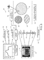
- FIG. 3 illustrates a flow chart of operations depicting logical operational steps of a Fisher image signature computation method 60, which can be performed in accordance with an alternative embodiment. That is, the schematic representation of the Fisher image signature (FIS) computation is shown in FIG. 3 .
- FIS Fisher image signature
- a set of local "patches" can be extracted, as shown as block 72.
- Local patches are sub-regions of the laser signature extracted, for example, by sampling from a regular grid of coordinates in different scales.
- Blocks 62 and 64 shown in FIG. 3 generally illustrate the computation of local features resulting in histograms 68, 70. That is, following processing of the laser depth projection operation depicted in block 72, gradient histograms can be implemented, as shown at block 74.
- a principal component analysis (PCA) operation can be performed on the gradient histogram(s) as shown at block 76 and graphically illustrated by the histogram graphic 86 located above block 76 and circles 78, 80, 82, 84 depicted below block 76.
- PCA principal component analysis
- a spatial pooling operation can be implemented, as depicted at block 92.
- the pooling operation will compute the Fisher vector with respect to the GMM using all the patches in the laser signal, independently for the different spatial regions defined.
- This operation is followed by an operation for normalizing signatures as indicated at block 100.
- the operations described at blocks 92, 100 are graphically illustrated by block 90 and normalized data sets 94, 96, 98.
- an operation can be performed in which profile slices clusters learned on the training set.
- MPP Mean Projection Profile
- FIG. 4 illustrates example graphics depicting mean front (upper row) and side (bottom row) profiles from 5 different vehicle classes corresponding to profile images, in accordance with the disclosed embodiments.
- Such data is indicated by graphs 110, 112, 114, 116, 118, 120 and 122, 124, 126, 128, 130, 132.
- Such features Before feeding the features into the classifiers, such features can be resized first to a fixed-length vector by interpolation and then L 2 -normalized.
- the present inventors experimented with different dimensions and lengths between 15 to 25 dimensions were found to be optimal for the dataset.
- the FLS Fisher Laser Signature
- h l ⁇ h lm ⁇
- m 1 ... W ⁇
- FLS Fish Vector
- the FLS is further square-rooted and L2-normalized.
- the laser profiles similarly to the profile images and compute a FLS for each part. Note that this corresponds to subdividing the slices of the laser scanner in first, middle and last set of laser slices and computing side projections from the corresponding partial laser profiles reconstructed separately.
- a schematic representation of the Fisher laser signature computation is depicted in FIG. 5 .
- FIG. 5 illustrates a flow chart of operations depicting logical operational steps of a Fischer image signature computation method 140 that can be performed in accordance with an alternative embodiment.
- cropped profiles are generated as shown at block 144 and a profile slicing operation is then implemented as indicated at block 152.
- graphic 142 and histogram representations 146, 148, 150 graphically illustrated these particular steps.
- a PCA operation can be performed on profiles slices.
- the graphics 156, 158, 162, 164 illustrate this operation.
- a spatial pooling operation can be implemented, as shown at block 170.
- normalized profile signatures are generated.
- Graphic 172 and data sets 174, 176, 178 graphically illustrate the operations shown in blocks 170, 180.
- profile slices clusters are learned on the training set, as shown at block 182.
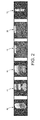
- FIG. 6 illustrates sample graphs 192, 194, 196, 198, 200, 2002 depicting 3D renderings of laser scanner profiles for six example vehicle classes from left to right as follows: passenger vehicle, passenger vehicle with one trailer, truck, truck with one trailer, truck with two trailers, and a motorcycle.
- the training set is used to estimate the classifier models (w and b), as well as any other models required in the feature vector computation such as the PCA and Gaussian mixture model (GMM) needed for the Fisher vectors representing the Fisher image signatures (FIS) and Fisher laser signatures (FLS).
- GMM Gaussian mixture model
- the validation set is used to select all the parameters (training parameters and feature parameters) for each feature type evaluated. This includes final dimensions (in the case of resizing or PCA projections), number of Gaussians and the parameters needed to train the SGD classifiers. Finally, for each feature type, the models corresponding to the best parameters are evaluated in the test set.
- MSP+ATT is the concatenation of the mean side profile (MFP) feature with the attribute based (ATT) features.
- These computer program instructions may also be stored in a computer-readable memory that can direct a computer or other programmable data-processing apparatus to function in a particular manner, such that the instructions stored in the computer-readable memory produce an article of manufacture including instruction means which implement the function/act specified in the block or blocks.
- the computer program instructions may also be loaded onto a computer or other programmable data-processing apparatus to cause a series of operational steps to be performed on the computer or other programmable apparatus to produce a computer implemented process such that the instructions which execute on the computer or other programmable apparatus provide steps for implementing the functions/acts specified in the block or blocks.
- FIGS. 7-8 are provided as exemplary diagrams of data-processing environments in which embodiments of the present invention may be implemented. It should be appreciated that FIG. 7-8 are only exemplary and are not intended to assert or imply any limitation with regard to the environments in which aspects or embodiments of the disclosed embodiments may be implemented. Many modifications to the depicted environments may be made without departing from the spirit and scope of the disclosed embodiments.
- a data-processing system 300 can include, for example, a central processor 301 (or other processors), a main memory 302, a controller 303, and in some embodiments, a USB (Universal Serial Bus) 304 or other appropriate peripheral connection.
- System 300 can also include an input device 305 (e.g., a keyboard, pointing device such as a mouse, etc), a display 306, and an HDD (Hard Disk Drive) 307 (e.g., mass storage).
- the various components of data-processing system 300 can communicate electronically through a system bus 310 or similar architecture.
- the system bus 310 may be, for example, a subsystem that transfers data between, for example, computer components within data-processing system 300 or to and from other data-processing devices, components, computers, etc.
- FIG. 8 illustrates a computer software system 350, which may be employed for directing the operation of the data-processing system 300 depicted in FIG. 7 .
- Software application 354, stored in memory 302 and/or on HDD 307 generally can include and/or can be associated with a kernel or operating system 351 and a shell or interface 353.
- One or more application programs, such as module(s) 352 may be "loaded” (i.e., transferred from mass storage or HDD 307 into the main memory 302) for execution by the data-processing system 300.
- module 352 can be implemented as, for example, a software module that performs the logical instructions or operations of FIGS. 1 , 3 , 5 and so forth.
- the data-processing system 300 can receive user commands and data through user interface 353 accessible by a user 349. These inputs may then be acted upon by the data-processing system 300 in accordance with instructions from operating system 351 and/or software application 354 and any software module(s) 352 thereof.
- program modules can include, but are not limited to routines, subroutines, software applications, programs, objects, components, data structures, etc., that perform particular tasks or implement particular abstract data types and instructions.
- routines e.g., module 352
- modules can include, but are not limited to routines, subroutines, software applications, programs, objects, components, data structures, etc., that perform particular tasks or implement particular abstract data types and instructions.
- program modules e.g., module 352
- program modules e.g., module 352
- modules can include, but are not limited to routines, subroutines, software applications, programs, objects, components, data structures, etc., that perform particular tasks or implement particular abstract data types and instructions.
- program modules e.g., module 352
- routines e.g., routines, subroutines, software applications, programs, objects,
- module may refer to a collection of routines and data structures that perform a particular task or implements a particular abstract data type. Modules may be composed of two parts: an interface, which lists the constants, data types, variable, and routines that can be accessed by other modules or routines, and an implementation, which is typically private (accessible only to that module) and which includes source code that actually implements the routines in the module.
- the term module may also simply refer to an application, such as a computer program designed to assist in the performance of a specific task, such as word processing, accounting, inventory management, etc.
- the interface 353 (e.g., a graphical user interface), can serve to display results, whereupon a user may supply additional inputs or terminate a particular session.
- operating system 151 and interface 353 can be implemented in the context of a "windows" system. It can be appreciated, of course, that other types of systems are potential. For example, rather than a traditional "windows" system, other operation systems, such as, for example, a real time operating system (RTOS) more commonly employed in wireless systems may also be employed with respect to operating system 351 and interface 353.
- RTOS real time operating system
- FIGS. 7-8 are thus intended as examples, and not as architectural limitations of disclosed embodiments. Additionally, such embodiments are not limited to any particular application or computing or data-processing environment. Instead, those skilled in the art will appreciate that the disclosed approach may be advantageously applied to a variety of systems and application software. Moreover, the disclosed embodiments can be embodied on a variety of different computing platforms, including Macintosh, Unix, Linux, and the like.
Landscapes
- Engineering & Computer Science (AREA)
- Theoretical Computer Science (AREA)
- General Physics & Mathematics (AREA)
- Physics & Mathematics (AREA)
- Computer Vision & Pattern Recognition (AREA)
- Multimedia (AREA)
- Health & Medical Sciences (AREA)
- General Health & Medical Sciences (AREA)
- Software Systems (AREA)
- Artificial Intelligence (AREA)
- Life Sciences & Earth Sciences (AREA)
- Evolutionary Computation (AREA)
- Data Mining & Analysis (AREA)
- Biomedical Technology (AREA)
- Databases & Information Systems (AREA)
- Computing Systems (AREA)
- Molecular Biology (AREA)
- Medical Informatics (AREA)
- Bioinformatics & Computational Biology (AREA)
- General Engineering & Computer Science (AREA)
- Evolutionary Biology (AREA)
- Bioinformatics & Cheminformatics (AREA)
- Human Computer Interaction (AREA)
- Traffic Control Systems (AREA)
- Image Analysis (AREA)
- Length Measuring Devices By Optical Means (AREA)
- Optical Radar Systems And Details Thereof (AREA)
- Measurement Of Optical Distance (AREA)
- Image Processing (AREA)
Applications Claiming Priority (1)
| Application Number | Priority Date | Filing Date | Title |
|---|---|---|---|
| US13/963,472 US9683836B2 (en) | 2013-08-09 | 2013-08-09 | Vehicle classification from laser scanners using fisher and profile signatures |
Publications (2)
| Publication Number | Publication Date |
|---|---|
| EP2846290A2 true EP2846290A2 (de) | 2015-03-11 |
| EP2846290A3 EP2846290A3 (de) | 2015-08-26 |
Family
ID=51454526
Family Applications (1)
| Application Number | Title | Priority Date | Filing Date |
|---|---|---|---|
| EP14179609.4A Ceased EP2846290A3 (de) | 2013-08-09 | 2014-08-01 | Fahrzeugklassifizierung von Laserabtastern mit Fisher- sowie Profilsignaturen |
Country Status (3)
| Country | Link |
|---|---|
| US (1) | US9683836B2 (de) |
| EP (1) | EP2846290A3 (de) |
| JP (2) | JP2015036684A (de) |
Cited By (1)
| Publication number | Priority date | Publication date | Assignee | Title |
|---|---|---|---|---|
| EP3035245A1 (de) * | 2014-12-17 | 2016-06-22 | Nuctech Company Limited | Fahrzeugarterkennungsverfahren und schnelles fahrzeugüberprüfungssystem mit dem verfahren |
Families Citing this family (19)
| Publication number | Priority date | Publication date | Assignee | Title |
|---|---|---|---|---|
| US10036812B2 (en) | 2015-06-24 | 2018-07-31 | Blackmore Sensors and Analytics Inc. | Method and system for three dimensional digital holographic aperture synthesis |
| US10586102B2 (en) * | 2015-08-18 | 2020-03-10 | Qualcomm Incorporated | Systems and methods for object tracking |
| US9984704B2 (en) | 2016-08-05 | 2018-05-29 | Electronics And Telecommunications Research Institute | Vehicle classification system and method |
| EP3548840B1 (de) | 2016-11-29 | 2023-10-11 | Blackmore Sensors & Analytics, LLC | Verfahren und system zum klassifizieren eines objekts in einem punktwolkendatensatz |
| US11624828B2 (en) | 2016-11-30 | 2023-04-11 | Blackmore Sensors & Analytics, Llc | Method and system for adaptive scanning with optical ranging systems |
| KR102399757B1 (ko) | 2016-11-30 | 2022-05-18 | 블랙모어 센서스 앤드 애널리틱스, 엘엘씨 | 광 처프 거리 검출의 도플러 검출 및 도플러 보정을 위한 방법 및 장치 |
| KR102254466B1 (ko) | 2016-11-30 | 2021-05-20 | 블랙모어 센서스 앤드 애널리틱스, 엘엘씨 | 광학 거리 측정 시스템을 이용한 자동적인 실시간 적응형 스캐닝 방법과 시스템 |
| US10422880B2 (en) | 2017-02-03 | 2019-09-24 | Blackmore Sensors and Analytics Inc. | Method and system for doppler detection and doppler correction of optical phase-encoded range detection |
| US10401495B2 (en) | 2017-07-10 | 2019-09-03 | Blackmore Sensors and Analytics Inc. | Method and system for time separated quadrature detection of doppler effects in optical range measurements |
| US10534084B2 (en) | 2017-07-27 | 2020-01-14 | Blackmore Sensors & Analytics, Llc | Method and system for using square wave digital chirp signal for optical chirped range detection |
| FR3078810B1 (fr) * | 2018-03-08 | 2020-04-03 | Idemia Identity And Security | Dispositif et procede pour differencier un poids lourd de transport de marchandises d’un autocar |
| EP4246176A3 (de) | 2018-04-23 | 2023-12-13 | Blackmore Sensors & Analytics, LLC | Verfahren und system zur steuerung eines autonomen fahrzeugs unter verwendung von optischen dopplersensoren mit kohärentem bereich |
| CN113260873A (zh) | 2019-01-04 | 2021-08-13 | 布莱克莫尔传感器和分析有限责任公司 | 带有具有折射分面的可旋转多边形偏转器的lidar设备 |
| US11822010B2 (en) | 2019-01-04 | 2023-11-21 | Blackmore Sensors & Analytics, Llc | LIDAR system |
| CN113050993A (zh) | 2019-12-27 | 2021-06-29 | 中兴通讯股份有限公司 | 基于激光雷达的检测方法、装置及计算机可读存储介质 |
| US12039807B2 (en) | 2020-07-27 | 2024-07-16 | Raytheon Company | Shape-based vehicle classification using laser scan and neural network |
| CN113361547B (zh) * | 2021-06-30 | 2024-06-14 | 深圳证券信息有限公司 | 一种签章识别方法、装置、设备及可读存储介质 |
| US12130363B2 (en) | 2022-02-03 | 2024-10-29 | Aurora Operations, Inc. | LIDAR system |
| US12571914B2 (en) | 2023-10-05 | 2026-03-10 | Aurora Operations, Inc. | Systems and methods of LIDAR sensor systems having amplifier protection circuits |
Family Cites Families (14)
| Publication number | Priority date | Publication date | Assignee | Title |
|---|---|---|---|---|
| JPH05225490A (ja) | 1992-02-07 | 1993-09-03 | Toshiba Corp | 車種判別装置 |
| US6304321B1 (en) | 1992-11-23 | 2001-10-16 | Schwartz Electro-Optics, Inc. | Vehicle classification and axle counting sensor system and method |
| US6195019B1 (en) * | 1998-01-20 | 2001-02-27 | Denso Corporation | Vehicle classifying apparatus and a toll system |
| US6337640B2 (en) | 1999-03-31 | 2002-01-08 | Diamond Consulting Services Limited | Inductive loop sensor for traffic detection, and traffic monitoring apparatus and method using such a loop sensor |
| US7970644B2 (en) | 2003-02-21 | 2011-06-28 | Accenture Global Services Limited | Electronic toll management and vehicle identification |
| CN101030259B (zh) * | 2006-02-28 | 2011-10-26 | 东软集团股份有限公司 | Svm分类器、利用svm分类器识别车辆图像的方法和装置 |
| US8111174B2 (en) | 2007-10-03 | 2012-02-07 | University Of Southern California | Acoustic signature recognition of running vehicles using spectro-temporal dynamic neural network |
| US8009062B2 (en) | 2008-09-22 | 2011-08-30 | Rothschild Leigh M | Vehicle traffic flow data acquisition and distribution |
| US8364334B2 (en) | 2008-10-30 | 2013-01-29 | Honeywell International Inc. | System and method for navigating an autonomous vehicle using laser detection and ranging |
| EP2496911B1 (de) | 2009-11-02 | 2016-04-20 | Infinity Laser Measuring LLC | Lasermessung eines fahrzeugrahmens |
| US8775424B2 (en) * | 2010-01-26 | 2014-07-08 | Xerox Corporation | System for creative image navigation and exploration |
| US8532399B2 (en) * | 2010-08-20 | 2013-09-10 | Xerox Corporation | Large scale image classification |
| US9298982B2 (en) | 2011-07-26 | 2016-03-29 | Xerox Corporation | System and method for computing the visual profile of a place |
| ES2659214T3 (es) * | 2011-09-13 | 2018-03-14 | Osi Optoelectronics | Sensor mejorado de telémetro de láser |
-
2013
- 2013-08-09 US US13/963,472 patent/US9683836B2/en active Active
-
2014
- 2014-07-23 JP JP2014149655A patent/JP2015036684A/ja active Pending
- 2014-08-01 EP EP14179609.4A patent/EP2846290A3/de not_active Ceased
-
2019
- 2019-09-17 JP JP2019168596A patent/JP2020080141A/ja active Pending
Non-Patent Citations (3)
| Title |
|---|
| "Methods in molecular biology", vol. 609, 30 October 2009, HUMANA PRESS, US, ISSN: 1064-3745, article ASA BEN-HUR ET AL: "A User's Guide to Support Vector Machines", pages: 223 - 239, XP055348408, DOI: 10.1007/978-1-60327-241-4_13 * |
| RYAN RIFKIN ET AL: "In Defense of One-Vs-All Classification", JOURNAL OF MACHINE LEARNING RESEARCH, MIT PRESS, CAMBRIDGE, MA, US, vol. 5, 1 December 2004 (2004-12-01), pages 101 - 141, XP058290931, ISSN: 1532-4435 * |
| URAZGHILDIIEV I R ET AL: "A vehicle classification svstem based on microwave radar measurement of height profiles", RADAR 2002 OCT. 15-17, 2002, PISCATAWAY, NJ, USA,IEEE, 15 October 2002 (2002-10-15), pages 409 - 413, XP010626904, ISBN: 978-0-85296-750-8 * |
Cited By (2)
| Publication number | Priority date | Publication date | Assignee | Title |
|---|---|---|---|---|
| EP3035245A1 (de) * | 2014-12-17 | 2016-06-22 | Nuctech Company Limited | Fahrzeugarterkennungsverfahren und schnelles fahrzeugüberprüfungssystem mit dem verfahren |
| US10074026B2 (en) | 2014-12-17 | 2018-09-11 | Nuctech Company Limited | Vehicle type recognition method and fast vehicle checking system using the same method |
Also Published As
| Publication number | Publication date |
|---|---|
| US9683836B2 (en) | 2017-06-20 |
| JP2015036684A (ja) | 2015-02-23 |
| JP2020080141A (ja) | 2020-05-28 |
| US20150046119A1 (en) | 2015-02-12 |
| EP2846290A3 (de) | 2015-08-26 |
Similar Documents
| Publication | Publication Date | Title |
|---|---|---|
| US9683836B2 (en) | Vehicle classification from laser scanners using fisher and profile signatures | |
| KR102269750B1 (ko) | Cnn을 활용한 카메라 및 라이다 센서 기반 실시간 객체 탐지 방법 | |
| Zeng et al. | Rt3d: Real-time 3-d vehicle detection in lidar point cloud for autonomous driving | |
| Guan et al. | Iterative tensor voting for pavement crack extraction using mobile laser scanning data | |
| Guan et al. | Using mobile LiDAR data for rapidly updating road markings | |
| Lehtomäki et al. | Object classification and recognition from mobile laser scanning point clouds in a road environment | |
| US9355320B2 (en) | Blur object tracker using group lasso method and apparatus | |
| US9607228B2 (en) | Parts based object tracking method and apparatus | |
| CN103189897B (zh) | 图像识别装置、图像识别方法和集成电路 | |
| DE102011117585B4 (de) | Systeme und Verfahren zum Verfolgen von Objekten | |
| CN109284664B (zh) | 驾驶员辅助系统和护栏检测方法 | |
| Sandhawalia et al. | Vehicle type classification from laser scanner profiles: A benchmark of feature descriptors | |
| Ding et al. | Fast lane detection based on bird’s eye view and improved random sample consensus algorithm | |
| US11468572B2 (en) | Image processing device, image recognition device, image processing program, and image recognition program | |
| JP5936561B2 (ja) | 画像における外観及びコンテキストに基づく物体分類 | |
| Holzer et al. | Learning to efficiently detect repeatable interest points in depth data | |
| US20150278632A1 (en) | Extending data-driven detection to the prediction of object part locations | |
| Liu et al. | LB-LSD: A length-based line segment detector for real-time applications | |
| US9519060B2 (en) | Methods and systems for vehicle classification from laser scans using global alignment | |
| Liu et al. | Visual object tracking with partition loss schemes | |
| CN105654104A (zh) | 一种基于多粒度特征的行人检测方法 | |
| Haselhoff et al. | On visual crosswalk detection for driver assistance systems | |
| CN119206530B (zh) | 一种遥感图像的动态目标识别方法、装置、设备及介质 | |
| WO2018143278A1 (ja) | 画像処理装置、画像認識装置、画像処理プログラム、及び画像認識プログラム | |
| CN117671616A (zh) | 一种目标识别方法、装置、设备和存储介质 |
Legal Events
| Date | Code | Title | Description |
|---|---|---|---|
| 17P | Request for examination filed |
Effective date: 20140801 |
|
| AK | Designated contracting states |
Kind code of ref document: A2 Designated state(s): AL AT BE BG CH CY CZ DE DK EE ES FI FR GB GR HR HU IE IS IT LI LT LU LV MC MK MT NL NO PL PT RO RS SE SI SK SM TR |
|
| AX | Request for extension of the european patent |
Extension state: BA ME |
|
| PUAI | Public reference made under article 153(3) epc to a published international application that has entered the european phase |
Free format text: ORIGINAL CODE: 0009012 |
|
| RIC1 | Information provided on ipc code assigned before grant |
Ipc: G06K 9/62 20060101ALI20150326BHEP Ipc: G06K 9/46 20060101ALI20150326BHEP Ipc: G06K 9/00 20060101AFI20150326BHEP |
|
| PUAL | Search report despatched |
Free format text: ORIGINAL CODE: 0009013 |
|
| AK | Designated contracting states |
Kind code of ref document: A3 Designated state(s): AL AT BE BG CH CY CZ DE DK EE ES FI FR GB GR HR HU IE IS IT LI LT LU LV MC MK MT NL NO PL PT RO RS SE SI SK SM TR |
|
| AX | Request for extension of the european patent |
Extension state: BA ME |
|
| RIC1 | Information provided on ipc code assigned before grant |
Ipc: G06K 9/00 20060101AFI20150721BHEP Ipc: G06K 9/46 20060101ALI20150721BHEP Ipc: G06K 9/62 20060101ALI20150721BHEP |
|
| R17P | Request for examination filed (corrected) |
Effective date: 20160226 |
|
| RBV | Designated contracting states (corrected) |
Designated state(s): AL AT BE BG CH CY CZ DE DK EE ES FI FR GB GR HR HU IE IS IT LI LT LU LV MC MK MT NL NO PL PT RO RS SE SI SK SM TR |
|
| 17Q | First examination report despatched |
Effective date: 20160809 |
|
| 18R | Application refused |
Effective date: 20171127 |