EP2846207B1 - Dimensionierung und Tuning-Methodik für optimierte Bewegungssteuerungskomponenten und Energieeffizienz - Google Patents
Dimensionierung und Tuning-Methodik für optimierte Bewegungssteuerungskomponenten und Energieeffizienz Download PDFInfo
- Publication number
- EP2846207B1 EP2846207B1 EP14182140.5A EP14182140A EP2846207B1 EP 2846207 B1 EP2846207 B1 EP 2846207B1 EP 14182140 A EP14182140 A EP 14182140A EP 2846207 B1 EP2846207 B1 EP 2846207B1
- Authority
- EP
- European Patent Office
- Prior art keywords
- motion
- motion control
- performance
- drive
- electronic
- Prior art date
- Legal status (The legal status is an assumption and is not a legal conclusion. Google has not performed a legal analysis and makes no representation as to the accuracy of the status listed.)
- Active
Links
Images


Classifications
-
- G—PHYSICS
- G05—CONTROLLING; REGULATING
- G05F—SYSTEMS FOR REGULATING ELECTRIC OR MAGNETIC VARIABLES
- G05F1/00—Automatic systems in which deviations of an electric quantity from one or more predetermined values are detected at the output of the system and fed back to a device within the system to restore the detected quantity to its predetermined value or values, i.e. retroactive systems
- G05F1/66—Regulating electric power
-
- G—PHYSICS
- G05—CONTROLLING; REGULATING
- G05B—CONTROL OR REGULATING SYSTEMS IN GENERAL; FUNCTIONAL ELEMENTS OF SUCH SYSTEMS; MONITORING OR TESTING ARRANGEMENTS FOR SUCH SYSTEMS OR ELEMENTS
- G05B13/00—Adaptive control systems, i.e. systems automatically adjusting themselves to have a performance which is optimum according to some preassigned criterion
- G05B13/02—Adaptive control systems, i.e. systems automatically adjusting themselves to have a performance which is optimum according to some preassigned criterion electric
- G05B13/04—Adaptive control systems, i.e. systems automatically adjusting themselves to have a performance which is optimum according to some preassigned criterion electric involving the use of models or simulators
- G05B13/042—Adaptive control systems, i.e. systems automatically adjusting themselves to have a performance which is optimum according to some preassigned criterion electric involving the use of models or simulators in which a parameter or coefficient is automatically adjusted to optimise the performance
-
- G—PHYSICS
- G01—MEASURING; TESTING
- G01R—MEASURING ELECTRIC VARIABLES; MEASURING MAGNETIC VARIABLES
- G01R21/00—Arrangements for measuring electric power or power factor
- G01R21/133—Arrangements for measuring electric power or power factor by using digital technique
-
- G—PHYSICS
- G05—CONTROLLING; REGULATING
- G05B—CONTROL OR REGULATING SYSTEMS IN GENERAL; FUNCTIONAL ELEMENTS OF SUCH SYSTEMS; MONITORING OR TESTING ARRANGEMENTS FOR SUCH SYSTEMS OR ELEMENTS
- G05B11/00—Automatic controllers
- G05B11/01—Automatic controllers electric
- G05B11/36—Automatic controllers electric with provision for obtaining particular characteristics, e.g. proportional, integral, differential
-
- G—PHYSICS
- G05—CONTROLLING; REGULATING
- G05B—CONTROL OR REGULATING SYSTEMS IN GENERAL; FUNCTIONAL ELEMENTS OF SUCH SYSTEMS; MONITORING OR TESTING ARRANGEMENTS FOR SUCH SYSTEMS OR ELEMENTS
- G05B17/00—Systems involving the use of models or simulators of said systems
- G05B17/02—Systems involving the use of models or simulators of said systems electric
-
- G—PHYSICS
- G06—COMPUTING OR CALCULATING; COUNTING
- G06F—ELECTRIC DIGITAL DATA PROCESSING
- G06F30/00—Computer-aided design [CAD]
- G06F30/20—Design optimisation, verification or simulation
-
- H—ELECTRICITY
- H02—GENERATION; CONVERSION OR DISTRIBUTION OF ELECTRIC POWER
- H02P—CONTROL OR REGULATION OF ELECTRIC MOTORS, ELECTRIC GENERATORS OR DYNAMO-ELECTRIC CONVERTERS; CONTROLLING TRANSFORMERS, REACTORS OR CHOKE COILS
- H02P21/00—Arrangements or methods for the control of electric machines by vector control, e.g. by control of field orientation
- H02P21/0003—Control strategies in general, e.g. linear type, e.g. P, PI, PID, using robust control
- H02P21/0017—Model reference adaptation, e.g. MRAS or MRAC, useful for control or parameter estimation
-
- H—ELECTRICITY
- H02—GENERATION; CONVERSION OR DISTRIBUTION OF ELECTRIC POWER
- H02P—CONTROL OR REGULATION OF ELECTRIC MOTORS, ELECTRIC GENERATORS OR DYNAMO-ELECTRIC CONVERTERS; CONTROLLING TRANSFORMERS, REACTORS OR CHOKE COILS
- H02P21/00—Arrangements or methods for the control of electric machines by vector control, e.g. by control of field orientation
- H02P21/0003—Control strategies in general, e.g. linear type, e.g. P, PI, PID, using robust control
- H02P21/0021—Control strategies in general, e.g. linear type, e.g. P, PI, PID, using robust control using different modes of control depending on a parameter, e.g. the speed
-
- H—ELECTRICITY
- H02—GENERATION; CONVERSION OR DISTRIBUTION OF ELECTRIC POWER
- H02P—CONTROL OR REGULATION OF ELECTRIC MOTORS, ELECTRIC GENERATORS OR DYNAMO-ELECTRIC CONVERTERS; CONTROLLING TRANSFORMERS, REACTORS OR CHOKE COILS
- H02P23/00—Arrangements or methods for the control of AC motors characterised by a control method other than vector control
- H02P23/0004—Control strategies in general, e.g. linear type, e.g. P, PI, PID, using robust control
- H02P23/0022—Model reference adaptation, e.g. MRAS or MRAC, useful for control or parameter estimation
-
- H—ELECTRICITY
- H02—GENERATION; CONVERSION OR DISTRIBUTION OF ELECTRIC POWER
- H02P—CONTROL OR REGULATION OF ELECTRIC MOTORS, ELECTRIC GENERATORS OR DYNAMO-ELECTRIC CONVERTERS; CONTROLLING TRANSFORMERS, REACTORS OR CHOKE COILS
- H02P6/00—Arrangements for controlling synchronous motors or other dynamo-electric motors using electronic commutation dependent on the rotor position; Electronic commutators therefor
- H02P6/34—Modelling or simulation for control purposes
-
- H—ELECTRICITY
- H02—GENERATION; CONVERSION OR DISTRIBUTION OF ELECTRIC POWER
- H02P—CONTROL OR REGULATION OF ELECTRIC MOTORS, ELECTRIC GENERATORS OR DYNAMO-ELECTRIC CONVERTERS; CONTROLLING TRANSFORMERS, REACTORS OR CHOKE COILS
- H02P6/00—Arrangements for controlling synchronous motors or other dynamo-electric motors using electronic commutation dependent on the rotor position; Electronic commutators therefor
- H02P6/08—Arrangements for controlling the speed or torque of a single motor
Definitions
- the present invention relates to the field of motion control systems, and, in particular, to sizing and tuning methodologies for implementing motion control systems.
- Motion control in the field of automation generally refers to controlling the position, velocity or torque/acceleration of machines or loads using some type of device, such as an electromagnetic motor or actuator.
- a servo mechanical device servomechanism
- drive having closed loop feedback is used, which provides error-sensing negative feedback to compensate for deviations in actual motion of the motor while attempting to follow a motion profile.
- a drive may power a motor according to a motion profile which, in turn, drives a load. Then, feedback is returned to the drive from the motor, which allows the drive to compensate for errors in the actual motion of the motor, periodically or continuously.
- a motion planner such as one residing in a motion planner, a programmable logic controller (“PLC”), a PLC with integrated motion planner (“PLC+”), an automation controller, an industrial PC (an x86 PC-based computing platform for industrial applications) or other device, is used to provide an electronic motion profile, or command trajectory, to the drive.
- the motion planner sends the electronic motion profile to the drive via a common industrial protocol (“CIP") control network, which is a network suitable for highly reliable and available real-time communication.
- Control networks commonly used include, for example, ControlNet, DeviceNet, EtherNet/IP, SERCOS, EtherCAT, Profibus and CIP Motion, whose specifications are published and whose protocols are used broadly by a number of manufacturers and suppliers.
- the motion planner may also send commands via an analog interface, such as +/- 10V, or digital pulse train, such as a Step and Direction Interface.
- an analog interface such as +/- 10V
- digital pulse train such as a Step and Direction Interface.
- partitioning of motion control components may vary, such as by industry.
- some implementations may provide a PLC, drive and motor in a single package
- Position and velocity control loops in the motion control system may be set by the industrial environment via proportional-integral-derivative ("PID") controllers and Feed-forward Gains, which may greatly impact the gain and phase response of the system and thus power/energy efficiency.
- PID proportional-integral-derivative
- Motion Analyzer for example, a software tool from Rockwell Automation, Inc., may be used to assist in the sizing and selection of machine components, and RSLogix5000, for example, may be used to configure, program and execute the motion control application.
- tuning parameters such as gain values for the PID controller, and the motion profile
- tuning parameters such as gain values for the PID controller, and the motion profile
- lower gain values increase energy efficiency but decrease performance
- higher gain values decrease energy efficiency but increase performance
- external disturbances in the system such as friction, variations according to temperature, and variations in manufactured components often lead to variances that are not fully considered.
- a motion control software tool that estimates and improves power/energy efficiency while maintaining performance is needed.
- a motion control software tool that enables a user to further define their motion control application to allow maximum power efficiency to be realized with minimized cost and machine footprint is needed.
- the inventors have recognized that a more accurate and efficient motion control system may be achieved by simulating performance of the motion control system for a given configuration to achieve a performance goal and minimum power (or energy) consumption.
- the simulation analysis considers a motion profile and one or more corresponding performance parameters, and the resulting configuration provides sizing for hardware elements, such as drives and motors, and settings or tunings for those elements.
- a performance parameter may characterize the electronic motion profile and/or mechanical load transmission, such as by establishing an acceptable level of corresponding performance or error. Performance parameters which may greatly impact the gain and phase response of the system and thus power/energy efficiency.
- Motion Analyzer for example, a software tool from Rockwell Automation, Inc., may be used to assist in the sizing and selection of machine components, and RSLogix5000, for example, may be used to configure, program and execute the motion control application.
- tuning parameters such as gain values for the PID controller, and the motion profile
- tuning parameters such as gain values for the PID controller, and the motion profile
- lower gain values increase energy efficiency but decrease performance
- higher gain values decrease energy efficiency but increase performance
- external disturbances in the system such as friction, variations according to temperature, and variations in manufactured components often lead to variances that are not fully considered.
- a motion control software tool that estimates and improves power/energy efficiency while maintaining performance is needed.
- a motion control software tool that enables a user to further define their motion control application to allow maximum power efficiency to be realized with minimized cost and machine footprint is needed.
- WO 01/16656 A1 relates to a closed-loop control of a servo motor (16) in which multiple closed-loop terms of a motor command are adaptively tuned and selectively activated to achieve both stable operation and improved performance.
- the motor command includes a first term proportional to an error signal, a second term based on the integral of the error signal, and a third term based on the rate of change of the measured feedback signal, and representing the kinetic energy of the system.
- the first term is continuously active, whereas the second term is only activated when the rate of change of the measured feedback signal is below a threshold, and the third term is only activated when the error signal is within a reference window, thereby allowing relatively high gains while ensuring stable operation.
- WO 2010/141046 A1 relates to embodiments which provide techniques, computer-readable media, and devices for allowing users to perform interactive design of controllers, such as PID controllers, in a free-form modeling environment. Users can tune controllers using characteristics familiar to typical users rather than having to specify gain values for the controller, which may be difficult for a user to relate to the performance of a controller.
- WO 2007/03559 A2 describes controller scaling and parameterization are. Techniques that can be improved by employing the scaling and parameterization include, but are not limited to, controller design, tuning and optimization.
- the scaling and parameterization methods described here apply to transfer function based controllers, including PID controllers.
- the parameterization methods also apply to state feedback and state observer based controllers, as well as linear active disturbance rejection (ADRC) controllers. Parameterization simplifies the use of ADRC.
- a discrete extended state observer (DESO) and a generalized extended state observer (GESO) are described. They improve the performance of the ESO and therefore ADRC.
- a tracking control algorithm is also described that improves the performance of the ADRC controller.;
- a general algorithm is described for applying ADRC to multi-input multi-output systems.
- the object of the present invention is to achieve a more accurate and efficient motion control system.
- the inventors have recognized that a more accurate and efficient motion control system may be achieved by simulating performance of the motion control system for a given configuration to achieve a performance goal and minimum power (or energy) consumption.
- the simulation analysis considers a motion profile and one or more corresponding performance parameters, and the resulting configuration provides sizing for hardware elements, such as drives and motors, and settings or tunings for those elements.
- a performance parameter may characterize the electronic motion profile and/or mechanical load transmission, such as by establishing an acceptable level of corresponding performance or error.
- the performance parameters may optionally be non-overlapping with respect to time.
- the motion control program may further comprise selecting a drive from among a plurality of drives having differing capabilities stored in a database.
- the drive may include a proportional-integral-derivative controller for controlling position, velocity, and acceleration, and the plurality of tuning parameters may be a plurality of gain values for the proportional-integral-derivative controller.
- the motion control program may further comprise displaying to a graphical user interface results comparing power consumed to performance of the motion control configuration.
- the displaying may allow selecting differing motion control configurations showing differing results.
- the motion control program may further comprise changing at least one of the electronic motion profile, the performance parameter and the plurality of tuning parameters to determine a motion control configuration optimized with respect to power consumed versus performance of the motion control configuration.
- Determining the motion control configuration may comprise simulating a trajectory of the electronic motion profile using a model stored in database and accumulating power consumption along the trajectory.
- the performance parameter may indicate a maximum position error or maximum velocity error.
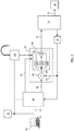
- a diagram of an exemplar industrial control system 10 comprises a motion planner 12, which may reside within, for example, a programmable logic controller ("PLC”), serially coupled to a modular servo mechanical drive 14 via an industrial control network 16 forming a network ring.
- PLC programmable logic controller
- the exemplar industrial control system 10 is shown using a network ring topology by way of example only and it will be appreciated that other such configurations and topologies, including but not limited to linear, daisy-chain and/or star topologies, may be readily used instead or in addition as known in the art.
- the industrial control network 16 may be a common industrial protocol (“CIP”) or other control network, and may be implemented via ControlNet, DeviceNet, EtherNet/IP, SERCOS EtherCAT, Profibus or CIP Motion as understood in the art.
- CIP common industrial protocol
- the motion planner 12 includes a processor, memory and data storage, and may be, for example, a Rockwell 1756 ControlLogix® system as available from Rockwell Automation, Inc.
- the drive 14 is adapted to power a motor, which carries out a physical motion for a machine or load over a period of time, and may be, for example, a Rockwell Kinetix 6000 multi-axis servo drive.
- the motion planner 12 couples to a first modular drive 14a of the drive 14 via a first control network segment 16a.
- the first modular drive 14a then couples to a second modular drive 14b of the drive 14 via a second control network segment 16b.
- the second modular drive 14b then couples to a third modular drive 14c of the drive 14 via a third control network segment 16c.
- the third modular drive 14c then couples to a fourth modular drive 14d of the drive 14 via a fourth control network segment 16d.
- the fourth modular drive 14d then couples to a fifth modular drive 14e of the drive 14 via a fifth control network segment 16e.
- the fifth modular drive 14e then couples to the motion planner 12 via a sixth control network segment 16f.
- Other embodiments may be implemented according to other topologies.
- the motion planner 12 also couples and communicates with an electronic computer 18 having a processor, memory and data storage over a computer network interface 19.
- the motion planner 12 and the computer 18 may each have input and output devices, such as a keyboard, mouse and monitor, and may each execute programs stored in non-transitory computer-readable storage medium, including ROM, RAM, flash, other solid state, disc, magnetic, optical or other drive, and provide a graphical user interface, which may include a touch screen monitor.
- the first modular drive 14a couples to a first electric motor 20 attached to a first machine or load 22.
- the first electric motor 20 provides rotary motion for causing the first machine or load 22 to complete a first industrial task, such as placing a box on a conveyor belt 24 upon triggering of a sensor 26 coupled to the first modular drive 14a.
- the second modular drive 14b couples to a second electric motor 28 attached to a second machine or load 30.
- the second electric motor 28 provides rotary motion for causing the second machine or load 30 to complete a second industrial task, such as rolling the conveyor belt 24.
- the third modular drive 14c couples to a third electric motor 32 attached to a third machine or load 34.
- the third electric motor 32 provides rotary motion for causing the third machine or load 34 to complete a third industrial task, such as filling the box that was placed on the conveyor belt 24.
- the fourth modular drive 14d couples to a fourth electric motor 36 attached to a fourth machine or load 38.
- the fourth electric motor 36 provides rotary motion for causing the fourth machine or load 38 to complete a fourth industrial task, such as closing the filled box.
- a fifth modular drive 14e couples to a fifth electric motor 40 attached to a fifth machine or load 42.
- the fifth electric motor 40 provides rotary motion for causing the fifth machine or load 42 to complete a fifth industrial task, such as rolling the same conveyor belt 24 or another conveyor belt.
- the motion planner 12 may couple to a sixth electric motor 44 for causing the sixth machine or load to complete a sixth industrial task, such as dispensing glue before the fourth machine or load 38 closes the filled box.
- a sixth industrial task such as dispensing glue before the fourth machine or load 38 closes the filled box.
- Other motions such as linear motions or hybrid motions, and/or other tasks may also be accomplished in the industrial control system 10.
- the motion planner 12, or the computer 18, executes a motion control program.
- the motion planner 12 provides an electronic motion profile (e.g., position or velocity), or command trajectory, for each of the electric motors 20, 28, 32, 36 and 40 in the industrial control system 10.
- the motion planner 12 provides a desired first motion profile for the first electric motor 20 to the first modular servo drive 14a; a desired second motion profile for the second electric motor 28 to the second modular servo drive 14b; and so forth, each through the control network 16.
- each of the electric motors 20, 28, 32, 36 and 40 in the industrial control system 10 is controlled by its respective modular drive 14a, 14b, 14c, 14d and 14e to carry out a respective desired motion profile.
- the first modular servo drive 14a controls the first electric motor 20 to drive the first machine or load 22 according to the desired first motion profile
- the second modular servo drive 14b controls the second electric motor 28 to drive the second machine or load 30 according to the desired second motion profile
- an exemplar closed loop motion control feedback system includes an electronic computer 60 having a processor, memory and data storage coupled via a network interface 62 to a motion planner 64.
- the motion planner 64 which may be for example a PLC, in turn, couples via an industrial control network 66 (or ⁇ 10V analog interface or digital pulse train) to a drive 68.
- the drive 68 couples via a power connection 70 to an electromagnetic actuator or motor 72.
- the motor 72 couples via a coupling 74 to a machine or load 76 for effecting physical motion in the load 76.
- the load 76 undergoes changes in position, velocity and/or acceleration.
- the load 76 having a mass put in motion, experiences various forces, losses and other external disturbances, including inertia and friction.
- the electronic computer 60 receives and stores an electronic motion profile characterizing a physical motion for the load 76 over a period of time and performance parameters characterizing an acceptable level of performance or error with respect to the electronic motion profile.
- Performance parameters may include, for example, any of the following: (1) maximum position error; (2) maximum velocity error; (3) maximum error for regions or sections of the electronic motion profile; (3) position settling time; (4) position repeatability; (5) position accuracy; (6) position bandwidth; (7) velocity bandwidth; (8) acceleration time; (9) motor thermal capacity; (10) motor temperature; and (11) drive temperature.
- the motion profile and performance parameters may be provided via user input at the electronic computer 60 or from the network interface 62, including from the Internet.
- the electronic computer 60 communicates via the network interface 62 with a database 78 which contains simulation modeling data for hardware products in the motion control system, such as drives, motors, cables, contactors, electromagnetic compatibility (“EMC”) filters, and so forth, and related algorithms.
- EMC electromagnetic compatibility
- a simulation may be performed from the electronic computer 60 using the electronic motion profile, performance parameters and simulation modeling data.
- the same or an optimized electronic motion profile, tuning parameters and other data is sent to the motion planner 64.
- the motion planner 64 sends the electronic motion profile to the drive 68 via the industrial control network 66.
- the drive 68 receives the electronic motion profile at a junction point 80, which may be a summer.
- the drive 68 compares the electronic motion profile from the industrial control network 66 to a feedback signal 82 at the junction point 80, which allows the drive 68 to compensate for errors in the actual motion of the motor 72 or the load 76 periodically or continuously.
- a resulting error 84 is transferred to a feedback implementing controller 86, which may be a proportional-integral-derivative ("PID") controller, or any type of feedback controller (e.g ., State Feedback, H-Infinity, PDFF, Fuzzy Logic, Kalman Filter, etc .).
- PID proportional-integral-derivative
- the feedback implementing controller 86 may receive the resulting error 84 at each of a proportional drive 90, an integral drive 92 and a derivative drive 94 within the feedback implementing controller 86.
- the motion planner 64 also provides the tuning parameters to the feedback implementing controller 86 via a tuning connection 85, which may be, for example, various feed forward position, velocity and/or acceleration gain values for the PID controller as understood in the art, including K pp , K pi , K vp , K vi , K vff and K aff .
- the output from the proportional drive 90, the integral drive 92 and the derivative drive 94 may be fed to a summation point 96, which, in turn, generates an appropriate amount of power/energy (current and voltage) via the power connection 70 for powering the motor 72.
- the motor 72 in turn, provides via a position or velocity sensor 98 the feedback signal 82 to the drive 68 and the motion planner 64 for providing adjustments.
- a power meter 100 may also monitor the amount of power/energy delivery to the drive 68 for powering the motor 72.
- the power meter 100 may provide feedback relating to power (or energy) consumption by the drive 68 to the motion planner 64.
- the motion planner 64, an energy controller (not shown) and/or the electronic computer 60 via the network interface 62 may verify energy demands and/or adjust the motion control system for power optimization. For example, the electronic motion profile and/or one or more of the performance parameters may be changed.
- an energy controller needs to regulate to a specific energy cost demand in a plant, the energy controller could set the motion profile to a slower rate to meet the energy cost demand.
- a user could set a machine from 1000 garments per minute to instead perform at 500 garments per minute to meet a high energy cost demand occurrence, such as higher energy costs in the evening.
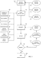
- a flow chart illustrates a motion control configuration process which may be implemented in a computer program in accordance with an embodiment of the invention.
- an electronic motion profile characterizing a physical motion for a load over a period of time is held in a first data element.
- performance parameters 1 through N characterizing the electronic motion profile are held in additional data elements. As described above with respect to Fig.
- performance parameters may include, for example, any of the following: (1) maximum position error; (2) maximum velocity error; (3) maximum error for regions or sections of the electronic motion profile; (3) position settling time; (4) position repeatability; (5) position accuracy; (6) position bandwidth; (7) velocity bandwidth; (8) acceleration time; (9) motor thermal capacity; (10) motor temperature; and (11) drive temperature.
- the performance parameters may optionally be non-overlapping with respect to time.
- each of the data elements from input blocks 110, 112 and 114 are received, which may be referred to as "user input,” although they may be machine or software generated in other embodiments.
- simulation and modeling data for the motion control system is loaded.
- the simulation and modeling data may include one or more of the following elements, each of which may be stored in a database: energy and performance models for motion planners, drives and other hardware at block 120; a position controller simulation model at block 122; a velocity controller simulation model at block 124; a position motor power/energy estimator at block 126; a drive power/energy estimator at block 128; and models of mechanical parameters, such as gearboxes, ball screws, couplings, and so forth, at block 130.
- an evaluation engine determines a motion control configuration comprising a drive adapted to power a motor carrying out the physical motion of the load and tuning parameters for the drive.
- the motion control configuration is determined based on implementing the electronic motion profile stored at input block 110 while substantially meeting the performance parameters at input blocks 112 and 114 with a minimum amount of power consumed.
- a drive which may include PID controllers, may be selected from among a plurality of drives having differing capabilities stored in a database, and gain values for the drive.
- results are displayed to a graphical user interface.
- the results may compare, for example, power consumed by the drive, the motor, the load and/or other components, or the motion control system as a whole, to performance of the motion control configuration. Performance may be measured, for example, by way of throughput, such as a configuration producing 1000 garments per minute.
- a user may be allowed to select differing motion control configurations, which may include differing bills of materials ("BOM”) and costs in the form of motors, drives and other hardware, and differing tuning parameters, showing differing results.
- BOM bills of materials
- a user program may be allowed to determine whether further optimization may be appropriate or not. If changes are not desired, in block 138, the flow chart concludes with an optimized motion control configuration. If changes are desired, the user or program may proceed to one or more of blocks 140, 142 and 144, which may include changing one or more of the electronic motion profile, the performance parameter and the motion control configuration, including the tuning parameters, respectively. Then, the process returns to the evaluation engine in block 132, displaying to the graphical user interface in block 134 and once again the decision block 136. This process may repeat iteratively for selecting an optimal configuration.
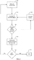
- a flow chart illustrates an algorithm of the motion control configuration of Fig. 3 in accordance with an embodiment of the invention.
- the evaluation engine simulates a trajectory of the electronic motion profile at a sampling point using simulation and modeling data for the motion control system which may be stored in database.
- the simulated trajectory is compared to the performance parameters characterizing the electronic motion profile.
- decision block 150 a determination is made if the presently selected configuration implements the electronic motion profile while substantially meeting the performance parameters.
- the configuration may be changed accordingly and the process may return to block 152.
- minimum power consumption may be calculated and accumulated for the sampling point along the trajectory.
- decision block 155 a determination is made if the electronic motion profile continues to another sampling point, and if so, the process repeats at block 146. Otherwise, the process ends at block 156.
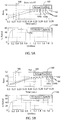
- an exemplar graph 160 illustrates an electronic motion profile 162 for an electric motor operating with a performance parameter representing a first error threshold or tolerance band 164.
- the first error threshold 164 comprises an upper limit 164a and lower limit 164b.
- the upper limit 164a and the lower limit 164b is less than a predefined percentage of the range of the motion profile 162, such as less than 5%.
- the electric motor variably increases in revolutions per minute ("RPM") over a period of time.
- RPM revolutions per minute
- the motion profile 162 begins to cross the lower limit 164b, which causes a servo mechanical device driving the electric motor to further increase the drive strength by providing more current (and power/energy) to the electric motor.
- a separate graph 168 illustrates a corresponding thermal capacity for the electric motor, which may also be shown via electric motor energy efficiency
- a steady state level 170 of approximately 55% is reached.
- capacity for an electric motor indicates a percent utilization of the motor (and related heat generated from the motor).
- an exemplar graph 180 illustrates a second electronic motion profile 182 for an electric motor operating with another performance parameter representing a second error threshold or tolerance band 184.
- the second error threshold 184 comprises an upper limit 184a and lower limit 184b.
- the second error threshold 184 is lesser ( i.e. , a tighter tolerance region) than the first error threshold 164 described above with respect to Fig. 5A .
- the electric motor again variably increases in RPM over a period of time.
- the motion profile 182 begins to cross the lower limit 184b, which causes a servo mechanical device driving the electric motor to further increase the drive strength by providing more current (and power/energy) to the electric motor.
- the motion profile 182 subsequently begins to cross the upper limit 184a, which causes the servo mechanical device driving the electric motor to decrease the drive strength by providing less current (and power/energy) to the electric motor.
- a separate graph 190 illustrates a corresponding thermal capacity for the electric motor, which may also be shown via electric motor energy efficiency.
- a steady state level 192 of approximately 52% is reached. This increase in motor capacity (and heat) is due to the electric motor's adherence to a tighter tolerance region which requires increased corrections.
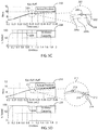
- an exemplar graph 200 illustrates in a focus region 201 a third electronic motion profile 202 for an electric motor operating with another performance parameter representing a third error threshold or tolerance band 204.
- the third error threshold 204 comprises an upper limit 204a and lower limit 204b.
- the third error threshold 204 is lesser ( i.e., a tighter tolerance region) than the first error threshold 164, described above with respect to Fig. 5A , and the second error threshold 184, described above with respect to Fig. 5B .
- the electric motor again variably increases in RPM over a period of time. Due to the even tighter tolerance region, the servo mechanical device driving the electric motor must increase and decrease the drive strength to the electric motor more often than before, such as correction at an approximate time 206 in the focus area 201.
- a separate graph 208 illustrates a corresponding thermal capacity for the electric motor, which may also be shown via electric motor energy efficiency.
- a steady state level 209 of approximately 80% is reached. This further increase in motor capacity (and heat) is again due to the electric motor's adherence to an even tighter tolerance region which requires even more corrections than before.
- an exemplar graph 210 illustrates in a focus region 211 a fourth electronic motion profile 212 for an electric motor operating with another performance parameter representing a fourth error threshold or tolerance band 214.
- the fourth error threshold 214 comprises an upper limit 214a and lower limit 214b.
- the fourth error threshold 214 is lesser ( i.e., a tighter tolerance region) than the first error threshold 164, described above with respect to Fig. 5A , the second error threshold 184, described above with respect to Fig. 5B , and the third error threshold 204, described above with respect to Fig. 5C .
- the electric motor again variably increases in RPM over a period of time. Due to the even tighter tolerance region, the servo mechanical device driving the electric motor must increase and decrease the drive strength to the electric motor more often than before, such as corrections at approximate times 216 and 218 in the focus area 211.
- a separate graph 220 illustrates a corresponding thermal capacity for the electric motor, which may also be shown via electric motor energy efficiency.
- a steady state level 224 of approximately 90% is reached. This further increase in motor capacity (and heat) is again due to the electric motor's adherence to an even tighter tolerance region which requires even more corrections than before. This may correspond, for example, to a period requiring high precision in the industrial process.
- an exemplar graph 230 illustrates a relative comparison between utilizations / thermal capacities for an electric motor and performance parameters representing error thresholds or tolerances.
- error thresholds increase along the x-axis (i. e., as tolerance regions loosen)
- motor utilization / thermal capacity decreases.
- a lesser error threshold i.e ., tighter tolerance
- +/- 0.05 RPM results in a motor utilization / thermal capacity of approximately 88%.
- a greater error threshold i.e ., looser tolerance
- +/- 0.35 RPM results in a lower motor utilization / thermal capacity of approximately 58%.
- an exemplar graph 240 illustrates a relative comparison between temperatures for the electric motor and performance parameters representing error thresholds or tolerances as corresponding to Fig. 6A .
- error thresholds increase along the x-axis (i.e ., as tolerance regions loosen)
- motor temperature decreases.
- the lesser error threshold i.e., tighter tolerance
- +/- 0.05 RPM results in a motor temperature of approximately 85 °C.
- a greater error threshold i.e ., looser tolerance
- +/- 0.35 RPM results in a lower motor temperature of approximately 45 °C.
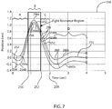
- an exemplar graph 250 illustrates an electronic motion profile 252 traversing through multiple sub-periods or regions "A,” “B,” “C” and “D,” each with differing performance parameters that are non-overlapping with respect to time in accordance with an embodiment of the invention.
- the electric motor changes position over a period of time.
- the motion profile 252 for the electric motor operates with a performance parameter representing a first error threshold or tolerance band 254.
- the first error threshold 254 comprises an upper limit 254a and lower limit 254b.
- the upper limit 254a and the lower limit 254b is less than 5% of the range of the motion profile 252. This may correspond to a sub-period requiring lesser precision in the industrial process.
- the motion planner provides the drive with a first set of tuning parameters in the first region A.
- the motion profile 252 enters the second region B.
- the motion profile 252 for the electric motor operates with a performance parameter representing a second, lesser error threshold or tolerance band 256 (i.e., a tighter tolerance region).
- the second error threshold 256 comprises an upper limit 256a and lower limit 256b. This may correspond to a sub-period requiring the highest precision in the industrial process. Consequently, in the second region B, the capacity for the electric motor would be at its highest. Accordingly, the motion planner provides the drive with a second set of tuning parameters in the second region B.
- the motion profile 252 enters the third region C.
- the motion profile 252 for the electric motor operates with a performance parameter representing a third error threshold or tolerance band 258 that is greater than the second error threshold 256 and equal to the first error threshold 254.
- the third error threshold 258 comprises an upper limit 258a and lower limit 258b. This may correspond to a sub-period requiring lesser precision in the industrial process. Accordingly, the motion planner provides the drive with a third set of tuning parameters in the third region B.
- the motion profile 252 enters the fourth region D.
- the motion profile 252 for the electric motor operates with a performance parameter representing a fourth error threshold or tolerance band 260 that is greater than the first error threshold 254, the second error threshold 256 and the third error threshold 258.
- the fourth error threshold 260 comprises an upper limit 260a and lower limit 260b. This may correspond to a sub-period requiring the least precision in the industrial process. Consequently, in the fourth region D, the capacity for the electric motor would be lowered. Accordingly, the motion planner provides the drive with a fourth set of tuning parameters in the fourth region B.
- error can be dynamically defined within multiple regions or zones of the motion profile, and the motion planner can adjust tuning parameters on the fly to realize minimum energy/power usage.
- the motion planner can adjust tuning parameters on the fly to realize minimum energy/power usage.
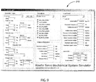
- exemplar graphical user interfaces display a simulation environment 300, simulation parameters and fields 310 and simulation output 320 in accordance with an embodiment of the invention.
- An electronic motion profile and performance parameters may be configured, and a simulation may be performed with results displayed, which may provide a motion control configuration implementing the electronic motion profile while substantially meeting the performance parameters with a minimum amount of power consumed.
- Fig. 11 is an exemplar graphical user interface displays results 330 comparing energy efficiency 332, which may be measured, at least in part, in Watts, or Kilowatt-Hours, to performance 334 of the motion control configuration, measured in garments per minute, in accordance with an embodiment of the invention.
- a first curve 336 displays four possible configurations, 336a-d, and a second curve 338 displays another five possible configurations, 338a-e. Each possible configuration allows a quick comparison between power consumed and performance for that configuration to customize maximum performance with minimum power consumption.
- a user may select a configuration, such as selected configuration 336b by highlighting with a mouse, and a resulting popup window may display details 340 for that configuration.
- Details 340 displayed may include a product or catalog number for a drive, a product or catalog number for an electric motor, a BOM and cost, an estimated total cost of ownership ("TCO") and/or tuning parameters, gain values and/or other settings for the configuration.
- TCO estimated total cost of ownership
- a user may determine and compare the effects of changes in the electronic motion profile, one or more performance parameters and/or the tuning parameters to optimize configurations with respect to power and performance.
- Alternative embodiments may implement various features described above in hardware and/or software and with varying levels of integration.
- alternative embodiments may combine or further separate or distribute hardware elements, or software elements, as may be appropriate for the task.
- a combined motion planner and electronic computer or a combined motion planner, electronic computer, drive and motor, may be used as understood in the art. Such alternative embodiments are within the scope of the invention.
- references to "a microprocessor” and “a processor” or “the microprocessor” and “the processor,” can be understood to include one or more microprocessors that can communicate in a stand-alone and/or a distributed environment(s), and can thus be configured to communicate via wired or wireless communications with other processors, where such one or more processor can be configured to operate on one or more processor-controlled devices that can be similar or different devices.
- references to memory can include one or more processor-readable and accessible memory elements and/or components that can be internal to the processor-controlled device, external to the processor-controlled device, and can be accessed via a wired or wireless network.
Landscapes
- Engineering & Computer Science (AREA)
- Power Engineering (AREA)
- Physics & Mathematics (AREA)
- General Physics & Mathematics (AREA)
- Automation & Control Theory (AREA)
- Evolutionary Computation (AREA)
- Health & Medical Sciences (AREA)
- Artificial Intelligence (AREA)
- Computer Vision & Pattern Recognition (AREA)
- Medical Informatics (AREA)
- Software Systems (AREA)
- Electromagnetism (AREA)
- Radar, Positioning & Navigation (AREA)
- Theoretical Computer Science (AREA)
- Geometry (AREA)
- General Engineering & Computer Science (AREA)
- Computer Hardware Design (AREA)
- Control Of Electric Motors In General (AREA)
- Feedback Control In General (AREA)
Claims (13)
- Bewegungssteuerungs-Konfigurationsprogramm, das in einem nicht-transitorischen, computerlesbaren Speichermedium gespeichert ist und auf einem elektronischen Computer ausgeführt werden kann, umfassend:ein erstes Datenelement, das ein elektronisches Bewegungsprofil speichert, das eine physikalische Bewegung für eine Last über eine Zeitperiode hinweg kennzeichnet,ein zweites Datenelement, das einen Performanzparameter speichert, der einen annehmbaren Fehlergrad in Bezug auf das elektronische Bewegungsprofil kennzeichnet, undeine Auswertungs-Engine, die eine Bewegungssteuerungs-Konfiguration bestimmt, die einen Antrieb zum Betreiben eines die physikalische Bewegung der Last ausführenden Motors und eine Vielzahl von Einstellungsparametern für den Antrieb umfasst,wobei die Bewegungssteuerungs-Konfiguration darauf basierend bestimmt wird, dass das in dem ersten Datenelement gespeicherte elektronische Bewegungsprofil implementiert wird, während der in dem zweiten Datenelement gespeicherte Performanzparameter mit einem minimalen Stromverbrauch im Wesentlichen erfüllt wird,wobei das Bestimmen der Bewegungssteuerungs-Konfiguration das Simulieren einer Bewegungsbahn des elektronischen Bewegungsprofils unter Verwendung eines in einer Datenbank gespeicherten Modells und das Akkumulieren des Stromverbrauchs entlang der Bewegungsbahn umfasst.
- Bewegungssteuerungsprogramm nach Anspruch 1, das weiterhin ein drittes Datenelement umfasst, das einen anderen Performanzparameter speichert, der einen annehmbaren Fehlergrad in Bezug auf das Bewegungsprofil kennzeichnet, wobei die Bewegungssteuerungskonfiguration darauf basierend bestimmt wird, dass das in dem ersten Datenelement gespeicherte elektronische Bewegungsprofil implementiert wird, während die in den zweiten und dritten Datenelementen gespeicherten Performanzparameter mit einem minimalen Stromverbrauch im Wesentlichen erfüllt werden.
- Bewegungssteuerungsprogramm nach Anspruch 2, wobei die Performanzparameter einander nicht in der Zeit überlappen.
- Bewegungssteuerungsprogramm nach einem der Ansprüche 1 bis 3, das weiterhin das Auswählen eines Antriebs aus einer Vielzahl von in einer Datenbank gespeicherten Antrieben mit unterschiedlichen Fähigkeiten umfasst.
- Bewegungssteuerungsprogramm nach Anspruch 4, wobei der Antrieb eine proportional-integral-derivative Steuereinrichtung enthält und wobei die Vielzahl von Einstellungsparametern eine Vielzahl von Verstärkungswerten für die proportional-integral-derivative Steuereinrichtung sind.
- Bewegungssteuerungsprogramm nach einem der Ansprüche 1 bis 5, das weiterhin das Anzeigen an einer grafischen Benutzerschnittstelle von Ergebnissen aus einem Vergleich der Energieeffizienz mit der Performanz der Bewegungssteuerungskonfiguration umfasst, wobei das Anzeigen das Auswählen von unterschiedlichen Bewegungssteuerungskonfigurationen mit verschiedenen Ergebnissen gestattet.
- Bewegungssteuerungsprogramm nach einem der Ansprüche 1 bis 6, das weiterhin das Ändern des elektronischen Bewegungsprofils, des Performanzparameters und/oder der Vielzahl von Einstellungsparametern umfasst, um eine Bewegungssteuerungskonfiguration zu bestimmen, die in Bezug auf den Stromverbrauch versus die Performanz der Bewegungssteuerungskonfiguration optimiert ist.
- Bewegungssteuerungsprogramm nach einem der Ansprüche 1 bis 7, wobei der Performanzparameter einen maximalen Positionsfehler angibt und/oder wobei der Performanzparameter einen maximalen Geschwindigkeitsfehler angibt.
- Verfahren zum Analysieren des Stromverbrauchs in einem Bewegungssteuerungssystem, umfassend:(a) Empfangen eines elektronischen Bewegungsprofils, das eine physikalische Bewegung für eine Last über eine Zeitperiode hinweg kennzeichnet,(b) Empfangen eines Performanzparameters, der einen annehmbaren Fehlergrad in Bezug auf das Bewegungsprofil kennzeichnet, und(c) Bestimmen einer Bewegungssteuerungskonfiguration, die einen Antrieb zum Betreiben eines die physikalische Bewegung der Last ausführenden Motors und eine Vielzahl von Einstellungsparametern für den Antrieb umfasst, wobei die Bewegungssteuerungs-Konfiguration darauf basierend bestimmt wird, dass das elektronische Bewegungsprofil implementiert wird, während der Performanzparameter mit einem minimalen Stromverbrauch im Wesentlichen erfüllt wird, wobei das Bestimmen der Bewegungssteuerungs-Konfiguration das Simulieren einer Bewegungsbahn des elektronischen Bewegungsprofils unter Verwendung eines in einer Datenbank gespeicherten Modells und das Akkumulieren des Stromverbrauchs entlang der Bewegungsbahn umfasst.
- Verfahren nach Anspruch 9, das weiterhin das Empfangen eines anderen Performanzparameters umfasst, der einen annehmbaren Fehlergrad in Bezug auf das Bewegungsprofil kennzeichnet, wobei die Bewegungssteuerungskonfiguration darauf basierend bestimmt wird, dass das elektronische Bewegungsprofil implementiert wird, während die Performanzparameter mit einem minimalen Stromverbrauch im Wesentlichen erfüllt werden, wobei die Performanzparameter einander nicht in der Zeit überlappen.
- Verfahren nach Anspruch 9 oder 10, das weiterhin das Auswählen eines Antriebs aus einer Vielzahl von in einer Datenbank gespeicherten Antrieben mit unterschiedlichen Fähigkeiten umfasst.
- Verfahren nach einem der Ansprüche 9 bis 11, das weiterhin das Anzeigen an einer grafischen Benutzerschnittstelle von Ergebnissen aus einem Vergleich der Energieeffizienz mit der Performanz der Bewegungssteuerungskonfiguration umfasst, wobei das Anzeigen das Auswählen von unterschiedlichen Bewegungssteuerungskonfigurationen mit verschiedenen Ergebnissen gestattet.
- Verfahren nach einem der Ansprüche 10 bis 12, das weiterhin das Ändern des elektronischen Bewegungsprofils, des Performanzparameters und/oder der Vielzahl von Einstellungsparametern umfasst, um eine Bewegungssteuerungskonfiguration zu bestimmen, die in Bezug auf den Stromverbrauch versus die Performanz der Bewegungssteuerungskonfiguration optimiert ist.
Applications Claiming Priority (1)
| Application Number | Priority Date | Filing Date | Title |
|---|---|---|---|
| US14/011,878 US9354651B2 (en) | 2013-08-28 | 2013-08-28 | Sizing and tuning methodology for optimized motion control components and energy efficiency |
Publications (2)
| Publication Number | Publication Date |
|---|---|
| EP2846207A1 EP2846207A1 (de) | 2015-03-11 |
| EP2846207B1 true EP2846207B1 (de) | 2017-10-18 |
Family
ID=51539123
Family Applications (1)
| Application Number | Title | Priority Date | Filing Date |
|---|---|---|---|
| EP14182140.5A Active EP2846207B1 (de) | 2013-08-28 | 2014-08-25 | Dimensionierung und Tuning-Methodik für optimierte Bewegungssteuerungskomponenten und Energieeffizienz |
Country Status (3)
| Country | Link |
|---|---|
| US (1) | US9354651B2 (de) |
| EP (1) | EP2846207B1 (de) |
| CN (1) | CN104423303B (de) |
Families Citing this family (11)
| Publication number | Priority date | Publication date | Assignee | Title |
|---|---|---|---|---|
| US20160098038A1 (en) * | 2014-10-01 | 2016-04-07 | Rockwell Automation Technologies, Inc. | Sizing and selection closer to the executing environment |
| US10551820B2 (en) * | 2015-06-03 | 2020-02-04 | Siemens Aktiengesellschaft | Method for calculating an optimized trajectory |
| CN105068002A (zh) * | 2015-08-19 | 2015-11-18 | 无锡市产品质量监督检验中心 | 使用最高车速测定电动自行车用直流轮毂电机实际功率的方法 |
| EP3165973B1 (de) * | 2015-11-03 | 2018-01-03 | Siemens Aktiengesellschaft | Verfahren zur rechnergestützten steuerung eines automatisierungssystems |
| US10345795B2 (en) | 2015-12-22 | 2019-07-09 | Rockwell Automation Technologies, Inc. | Systems and methods to enhance machine designs and production rate schedules for minimized energy cost |
| US20170315517A1 (en) * | 2016-04-28 | 2017-11-02 | Rockwell Automation Technologies, Inc. | Systems and methods to reduce energy usage of industrial machines using an enhanced motion profile |
| EP3367185A1 (de) * | 2017-02-28 | 2018-08-29 | Siemens Aktiengesellschaft | Antriebssystem und dessen beurteilung |
| US10291166B2 (en) | 2017-03-13 | 2019-05-14 | Rockwell Automation Technologies, Inc. | System and method of single parameter ratiometric tuning for motor drives |
| US10754320B2 (en) * | 2017-11-14 | 2020-08-25 | Rockwell Automation Technologies, Inc. | Method and apparatus for integrating an external motion planner with an industrial controller |
| CN110125939B (zh) * | 2019-06-03 | 2020-10-20 | 湖南工学院 | 一种机器人虚拟可视化控制的方法 |
| CN112476423B (zh) * | 2020-11-12 | 2022-03-08 | 腾讯科技(深圳)有限公司 | 机器人的关节电机控制方法、装置、设备及存储介质 |
Family Cites Families (6)
| Publication number | Priority date | Publication date | Assignee | Title |
|---|---|---|---|---|
| US6487458B1 (en) | 1999-08-31 | 2002-11-26 | Delphi Technologies, Inc. | Adaptive closed-loop servo control |
| WO2007035559A2 (en) | 2005-09-19 | 2007-03-29 | Cleveland State University | Controllers, observers, and applications thereof |
| US7919940B2 (en) * | 2007-10-21 | 2011-04-05 | Ge Intelligent Platforms, Inc. | System and method for jerk limited trajectory planning for a path planner |
| DE102009023475A1 (de) * | 2009-06-02 | 2010-12-09 | Robert Bosch Gmbh | Verfahren und Vorrichtung zur Generierung eines variablen Bewegungsprofils für eine Antriebseinheit einer Maschine |
| US8467888B2 (en) | 2009-06-05 | 2013-06-18 | The Mathworks, Inc. | Automated PID controller design |
| EP2454182B1 (de) * | 2009-07-15 | 2019-08-28 | Otis Elevator Company | Energieeinsparung mit optimierten bewegungsprofilen |
-
2013
- 2013-08-28 US US14/011,878 patent/US9354651B2/en active Active
-
2014
- 2014-08-25 EP EP14182140.5A patent/EP2846207B1/de active Active
- 2014-08-28 CN CN201410433160.5A patent/CN104423303B/zh active Active
Non-Patent Citations (1)
| Title |
|---|
| None * |
Also Published As
| Publication number | Publication date |
|---|---|
| US9354651B2 (en) | 2016-05-31 |
| US20150066400A1 (en) | 2015-03-05 |
| CN104423303A (zh) | 2015-03-18 |
| CN104423303B (zh) | 2017-03-15 |
| EP2846207A1 (de) | 2015-03-11 |
Similar Documents
| Publication | Publication Date | Title |
|---|---|---|
| EP2846207B1 (de) | Dimensionierung und Tuning-Methodik für optimierte Bewegungssteuerungskomponenten und Energieeffizienz | |
| US8280533B2 (en) | Continuously scheduled model parameter based adaptive controller | |
| CN110832422B (zh) | 机器学习装置、校正参数调整装置及机器学习方法 | |
| JP6517567B2 (ja) | サーボモータ制御装置及び衝突検出方法 | |
| EP2728425A1 (de) | Online-Integration von modellbasierter Optimierung und modellloser Steuerung | |
| CN111164520A (zh) | 机械设备控制系统、机械设备控制装置以及机械设备控制方法 | |
| US11137728B2 (en) | Processing device, control parameter determination method, and non-transitory recording medium storing a control parameter determination program | |
| JP7517774B2 (ja) | 非周期的に更新されるコントローラにおける速度に基づく制御、プロセスを制御する方法、プロセスコントローラ | |
| Stemmler et al. | Model predictive feed rate control for a milling machine | |
| CN109388099B (zh) | 利用模型支持的误差补偿对工件的加工 | |
| JP7003623B2 (ja) | 制御システム | |
| US9684288B2 (en) | Motion control systems with improved energy efficiency | |
| EP2913724B1 (de) | Sps mit endlichem horizontoptimierungssteuerprogramm | |
| Aghaee et al. | BLDC motor speed control based on MPC sliding mode multi-loop control strategy–implementation on Matlab and Arduino software | |
| Isa et al. | Comparative study of PID controlled modes on automatic water level measurement system | |
| CN108983598B (zh) | 一种pid调节方法、系统和存储装置 | |
| CN104126156B (zh) | 命令和控制自动化单元的电动机及所连接的系统的方法 | |
| Abad et al. | Intelligent tuning of PID controllers: Comprehensive approach based on modified Particle Swarm Optimization (PSO) algorithm | |
| US20200174436A1 (en) | Automatic optimization of the parameterization of a movement controller | |
| EP4582883A1 (de) | Verfahren zur bestimmung mindestens eines betriebsparameters einer komponente eines geschlossenen regelkreises | |
| Kaldate et al. | PLC Based PID Speed Control System | |
| CN109067288B (zh) | 一种基于电流环的电机控制方法及装置 | |
| CN121541489B (zh) | 一种用于多轴伺服系统的协同控制与扰动抑制方法 | |
| Khasanov et al. | The multiprocessor control system of dynamics multiply connected technological electric drives | |
| Melgarejo et al. | Closed-Loop Control and Sensor Noise Reduction in a Low-Cost Aerodynamic Pendulum Using Digital PID and Kalman Filtering on Arduino Mega |
Legal Events
| Date | Code | Title | Description |
|---|---|---|---|
| 17P | Request for examination filed |
Effective date: 20140825 |
|
| AK | Designated contracting states |
Kind code of ref document: A1 Designated state(s): AL AT BE BG CH CY CZ DE DK EE ES FI FR GB GR HR HU IE IS IT LI LT LU LV MC MK MT NL NO PL PT RO RS SE SI SK SM TR |
|
| AX | Request for extension of the european patent |
Extension state: BA ME |
|
| PUAI | Public reference made under article 153(3) epc to a published international application that has entered the european phase |
Free format text: ORIGINAL CODE: 0009012 |
|
| R17P | Request for examination filed (corrected) |
Effective date: 20150911 |
|
| RBV | Designated contracting states (corrected) |
Designated state(s): AL AT BE BG CH CY CZ DE DK EE ES FI FR GB GR HR HU IE IS IT LI LT LU LV MC MK MT NL NO PL PT RO RS SE SI SK SM TR |
|
| REG | Reference to a national code |
Ref country code: DE Ref legal event code: R079 Ref document number: 602014015888 Country of ref document: DE Free format text: PREVIOUS MAIN CLASS: G05B0019409000 Ipc: G05B0013040000 |
|
| GRAP | Despatch of communication of intention to grant a patent |
Free format text: ORIGINAL CODE: EPIDOSNIGR1 |
|
| RIC1 | Information provided on ipc code assigned before grant |
Ipc: G05B 11/36 20060101ALI20170516BHEP Ipc: H02P 6/34 20160101ALI20170516BHEP Ipc: G06F 17/50 20060101ALI20170516BHEP Ipc: G05B 19/409 20060101ALI20170516BHEP Ipc: H02P 21/00 20160101ALI20170516BHEP Ipc: G05F 1/66 20060101ALI20170516BHEP Ipc: G05B 17/02 20060101ALI20170516BHEP Ipc: G05B 13/04 20060101AFI20170516BHEP Ipc: G01R 21/133 20060101ALI20170516BHEP Ipc: H02P 6/08 20160101ALN20170516BHEP Ipc: H02P 6/00 20160101ALI20170516BHEP Ipc: H02P 23/00 20160101ALI20170516BHEP |
|
| INTG | Intention to grant announced |
Effective date: 20170602 |
|
| GRAS | Grant fee paid |
Free format text: ORIGINAL CODE: EPIDOSNIGR3 |
|
| GRAA | (expected) grant |
Free format text: ORIGINAL CODE: 0009210 |
|
| AK | Designated contracting states |
Kind code of ref document: B1 Designated state(s): AL AT BE BG CH CY CZ DE DK EE ES FI FR GB GR HR HU IE IS IT LI LT LU LV MC MK MT NL NO PL PT RO RS SE SI SK SM TR |
|
| REG | Reference to a national code |
Ref country code: GB Ref legal event code: FG4D |
|
| REG | Reference to a national code |
Ref country code: CH Ref legal event code: EP |
|
| REG | Reference to a national code |
Ref country code: AT Ref legal event code: REF Ref document number: 938479 Country of ref document: AT Kind code of ref document: T Effective date: 20171115 Ref country code: IE Ref legal event code: FG4D |
|
| REG | Reference to a national code |
Ref country code: DE Ref legal event code: R096 Ref document number: 602014015888 Country of ref document: DE |
|
| REG | Reference to a national code |
Ref country code: NL Ref legal event code: MP Effective date: 20171018 |
|
| REG | Reference to a national code |
Ref country code: LT Ref legal event code: MG4D |
|
| REG | Reference to a national code |
Ref country code: AT Ref legal event code: MK05 Ref document number: 938479 Country of ref document: AT Kind code of ref document: T Effective date: 20171018 |
|
| PG25 | Lapsed in a contracting state [announced via postgrant information from national office to epo] |
Ref country code: NL Free format text: LAPSE BECAUSE OF FAILURE TO SUBMIT A TRANSLATION OF THE DESCRIPTION OR TO PAY THE FEE WITHIN THE PRESCRIBED TIME-LIMIT Effective date: 20171018 |
|
| PG25 | Lapsed in a contracting state [announced via postgrant information from national office to epo] |
Ref country code: NO Free format text: LAPSE BECAUSE OF FAILURE TO SUBMIT A TRANSLATION OF THE DESCRIPTION OR TO PAY THE FEE WITHIN THE PRESCRIBED TIME-LIMIT Effective date: 20180118 Ref country code: SE Free format text: LAPSE BECAUSE OF FAILURE TO SUBMIT A TRANSLATION OF THE DESCRIPTION OR TO PAY THE FEE WITHIN THE PRESCRIBED TIME-LIMIT Effective date: 20171018 Ref country code: ES Free format text: LAPSE BECAUSE OF FAILURE TO SUBMIT A TRANSLATION OF THE DESCRIPTION OR TO PAY THE FEE WITHIN THE PRESCRIBED TIME-LIMIT Effective date: 20171018 Ref country code: LT Free format text: LAPSE BECAUSE OF FAILURE TO SUBMIT A TRANSLATION OF THE DESCRIPTION OR TO PAY THE FEE WITHIN THE PRESCRIBED TIME-LIMIT Effective date: 20171018 Ref country code: FI Free format text: LAPSE BECAUSE OF FAILURE TO SUBMIT A TRANSLATION OF THE DESCRIPTION OR TO PAY THE FEE WITHIN THE PRESCRIBED TIME-LIMIT Effective date: 20171018 |
|
| PG25 | Lapsed in a contracting state [announced via postgrant information from national office to epo] |
Ref country code: RS Free format text: LAPSE BECAUSE OF FAILURE TO SUBMIT A TRANSLATION OF THE DESCRIPTION OR TO PAY THE FEE WITHIN THE PRESCRIBED TIME-LIMIT Effective date: 20171018 Ref country code: LV Free format text: LAPSE BECAUSE OF FAILURE TO SUBMIT A TRANSLATION OF THE DESCRIPTION OR TO PAY THE FEE WITHIN THE PRESCRIBED TIME-LIMIT Effective date: 20171018 Ref country code: GR Free format text: LAPSE BECAUSE OF FAILURE TO SUBMIT A TRANSLATION OF THE DESCRIPTION OR TO PAY THE FEE WITHIN THE PRESCRIBED TIME-LIMIT Effective date: 20180119 Ref country code: HR Free format text: LAPSE BECAUSE OF FAILURE TO SUBMIT A TRANSLATION OF THE DESCRIPTION OR TO PAY THE FEE WITHIN THE PRESCRIBED TIME-LIMIT Effective date: 20171018 Ref country code: BG Free format text: LAPSE BECAUSE OF FAILURE TO SUBMIT A TRANSLATION OF THE DESCRIPTION OR TO PAY THE FEE WITHIN THE PRESCRIBED TIME-LIMIT Effective date: 20180118 Ref country code: IS Free format text: LAPSE BECAUSE OF FAILURE TO SUBMIT A TRANSLATION OF THE DESCRIPTION OR TO PAY THE FEE WITHIN THE PRESCRIBED TIME-LIMIT Effective date: 20180218 Ref country code: AT Free format text: LAPSE BECAUSE OF FAILURE TO SUBMIT A TRANSLATION OF THE DESCRIPTION OR TO PAY THE FEE WITHIN THE PRESCRIBED TIME-LIMIT Effective date: 20171018 |
|
| REG | Reference to a national code |
Ref country code: DE Ref legal event code: R097 Ref document number: 602014015888 Country of ref document: DE |
|
| PG25 | Lapsed in a contracting state [announced via postgrant information from national office to epo] |
Ref country code: EE Free format text: LAPSE BECAUSE OF FAILURE TO SUBMIT A TRANSLATION OF THE DESCRIPTION OR TO PAY THE FEE WITHIN THE PRESCRIBED TIME-LIMIT Effective date: 20171018 Ref country code: DK Free format text: LAPSE BECAUSE OF FAILURE TO SUBMIT A TRANSLATION OF THE DESCRIPTION OR TO PAY THE FEE WITHIN THE PRESCRIBED TIME-LIMIT Effective date: 20171018 Ref country code: CZ Free format text: LAPSE BECAUSE OF FAILURE TO SUBMIT A TRANSLATION OF THE DESCRIPTION OR TO PAY THE FEE WITHIN THE PRESCRIBED TIME-LIMIT Effective date: 20171018 Ref country code: SK Free format text: LAPSE BECAUSE OF FAILURE TO SUBMIT A TRANSLATION OF THE DESCRIPTION OR TO PAY THE FEE WITHIN THE PRESCRIBED TIME-LIMIT Effective date: 20171018 |
|
| PLBE | No opposition filed within time limit |
Free format text: ORIGINAL CODE: 0009261 |
|
| STAA | Information on the status of an ep patent application or granted ep patent |
Free format text: STATUS: NO OPPOSITION FILED WITHIN TIME LIMIT |
|
| REG | Reference to a national code |
Ref country code: FR Ref legal event code: PLFP Year of fee payment: 5 |
|
| PG25 | Lapsed in a contracting state [announced via postgrant information from national office to epo] |
Ref country code: SM Free format text: LAPSE BECAUSE OF FAILURE TO SUBMIT A TRANSLATION OF THE DESCRIPTION OR TO PAY THE FEE WITHIN THE PRESCRIBED TIME-LIMIT Effective date: 20171018 Ref country code: PL Free format text: LAPSE BECAUSE OF FAILURE TO SUBMIT A TRANSLATION OF THE DESCRIPTION OR TO PAY THE FEE WITHIN THE PRESCRIBED TIME-LIMIT Effective date: 20171018 Ref country code: RO Free format text: LAPSE BECAUSE OF FAILURE TO SUBMIT A TRANSLATION OF THE DESCRIPTION OR TO PAY THE FEE WITHIN THE PRESCRIBED TIME-LIMIT Effective date: 20171018 Ref country code: IT Free format text: LAPSE BECAUSE OF FAILURE TO SUBMIT A TRANSLATION OF THE DESCRIPTION OR TO PAY THE FEE WITHIN THE PRESCRIBED TIME-LIMIT Effective date: 20171018 |
|
| 26N | No opposition filed |
Effective date: 20180719 |
|
| PG25 | Lapsed in a contracting state [announced via postgrant information from national office to epo] |
Ref country code: SI Free format text: LAPSE BECAUSE OF FAILURE TO SUBMIT A TRANSLATION OF THE DESCRIPTION OR TO PAY THE FEE WITHIN THE PRESCRIBED TIME-LIMIT Effective date: 20171018 |
|
| PG25 | Lapsed in a contracting state [announced via postgrant information from national office to epo] |
Ref country code: MC Free format text: LAPSE BECAUSE OF FAILURE TO SUBMIT A TRANSLATION OF THE DESCRIPTION OR TO PAY THE FEE WITHIN THE PRESCRIBED TIME-LIMIT Effective date: 20171018 |
|
| REG | Reference to a national code |
Ref country code: CH Ref legal event code: PL |
|
| PG25 | Lapsed in a contracting state [announced via postgrant information from national office to epo] |
Ref country code: LI Free format text: LAPSE BECAUSE OF NON-PAYMENT OF DUE FEES Effective date: 20180831 Ref country code: LU Free format text: LAPSE BECAUSE OF NON-PAYMENT OF DUE FEES Effective date: 20180825 Ref country code: CH Free format text: LAPSE BECAUSE OF NON-PAYMENT OF DUE FEES Effective date: 20180831 |
|
| REG | Reference to a national code |
Ref country code: BE Ref legal event code: MM Effective date: 20180831 |
|
| PG25 | Lapsed in a contracting state [announced via postgrant information from national office to epo] |
Ref country code: BE Free format text: LAPSE BECAUSE OF NON-PAYMENT OF DUE FEES Effective date: 20180831 |
|
| PG25 | Lapsed in a contracting state [announced via postgrant information from national office to epo] |
Ref country code: MT Free format text: LAPSE BECAUSE OF NON-PAYMENT OF DUE FEES Effective date: 20180825 |
|
| PG25 | Lapsed in a contracting state [announced via postgrant information from national office to epo] |
Ref country code: TR Free format text: LAPSE BECAUSE OF FAILURE TO SUBMIT A TRANSLATION OF THE DESCRIPTION OR TO PAY THE FEE WITHIN THE PRESCRIBED TIME-LIMIT Effective date: 20171018 |
|
| PG25 | Lapsed in a contracting state [announced via postgrant information from national office to epo] |
Ref country code: HU Free format text: LAPSE BECAUSE OF FAILURE TO SUBMIT A TRANSLATION OF THE DESCRIPTION OR TO PAY THE FEE WITHIN THE PRESCRIBED TIME-LIMIT; INVALID AB INITIO Effective date: 20140825 Ref country code: PT Free format text: LAPSE BECAUSE OF FAILURE TO SUBMIT A TRANSLATION OF THE DESCRIPTION OR TO PAY THE FEE WITHIN THE PRESCRIBED TIME-LIMIT Effective date: 20171018 |
|
| PG25 | Lapsed in a contracting state [announced via postgrant information from national office to epo] |
Ref country code: MK Free format text: LAPSE BECAUSE OF NON-PAYMENT OF DUE FEES Effective date: 20171018 Ref country code: CY Free format text: LAPSE BECAUSE OF FAILURE TO SUBMIT A TRANSLATION OF THE DESCRIPTION OR TO PAY THE FEE WITHIN THE PRESCRIBED TIME-LIMIT Effective date: 20171018 Ref country code: IE Free format text: LAPSE BECAUSE OF NON-PAYMENT OF DUE FEES Effective date: 20180825 |
|
| PG25 | Lapsed in a contracting state [announced via postgrant information from national office to epo] |
Ref country code: AL Free format text: LAPSE BECAUSE OF FAILURE TO SUBMIT A TRANSLATION OF THE DESCRIPTION OR TO PAY THE FEE WITHIN THE PRESCRIBED TIME-LIMIT Effective date: 20171018 |
|
| P01 | Opt-out of the competence of the unified patent court (upc) registered |
Effective date: 20230404 |
|
| PGFP | Annual fee paid to national office [announced via postgrant information from national office to epo] |
Ref country code: DE Payment date: 20250724 Year of fee payment: 12 |
|
| PGFP | Annual fee paid to national office [announced via postgrant information from national office to epo] |
Ref country code: GB Payment date: 20250725 Year of fee payment: 12 |
|
| PGFP | Annual fee paid to national office [announced via postgrant information from national office to epo] |
Ref country code: FR Payment date: 20250723 Year of fee payment: 12 |