EP2846177A1 - Optical fiber transmission line - Google Patents
Optical fiber transmission line Download PDFInfo
- Publication number
- EP2846177A1 EP2846177A1 EP14183348.3A EP14183348A EP2846177A1 EP 2846177 A1 EP2846177 A1 EP 2846177A1 EP 14183348 A EP14183348 A EP 14183348A EP 2846177 A1 EP2846177 A1 EP 2846177A1
- Authority
- EP
- European Patent Office
- Prior art keywords
- fibers
- optical
- optical fiber
- transmission line
- splice
- Prior art date
- Legal status (The legal status is an assumption and is not a legal conclusion. Google has not performed a legal analysis and makes no representation as to the accuracy of the status listed.)
- Withdrawn
Links
Images




Classifications
-
- H—ELECTRICITY
- H04—ELECTRIC COMMUNICATION TECHNIQUE
- H04B—TRANSMISSION
- H04B10/00—Transmission systems employing electromagnetic waves other than radio-waves, e.g. infrared, visible or ultraviolet light, or employing corpuscular radiation, e.g. quantum communication
- H04B10/29—Repeaters
-
- G—PHYSICS
- G02—OPTICS
- G02B—OPTICAL ELEMENTS, SYSTEMS OR APPARATUS
- G02B6/00—Light guides; Structural details of arrangements comprising light guides and other optical elements, e.g. couplings
- G02B6/02—Optical fibres with cladding with or without a coating
- G02B6/02004—Optical fibres with cladding with or without a coating characterised by the core effective area or mode field radius
- G02B6/02009—Large effective area or mode field radius, e.g. to reduce nonlinear effects in single mode fibres
- G02B6/02014—Effective area greater than 60 square microns in the C band, i.e. 1530-1565 nm
- G02B6/02019—Effective area greater than 90 square microns in the C band, i.e. 1530-1565 nm
-
- G—PHYSICS
- G02—OPTICS
- G02B—OPTICAL ELEMENTS, SYSTEMS OR APPARATUS
- G02B6/00—Light guides; Structural details of arrangements comprising light guides and other optical elements, e.g. couplings
- G02B6/02—Optical fibres with cladding with or without a coating
- G02B6/036—Optical fibres with cladding with or without a coating core or cladding comprising multiple layers
- G02B6/03605—Highest refractive index not on central axis
- G02B6/03611—Highest index adjacent to central axis region, e.g. annular core, coaxial ring, centreline depression affecting waveguiding
-
- G—PHYSICS
- G02—OPTICS
- G02B—OPTICAL ELEMENTS, SYSTEMS OR APPARATUS
- G02B6/00—Light guides; Structural details of arrangements comprising light guides and other optical elements, e.g. couplings
- G02B6/02—Optical fibres with cladding with or without a coating
- G02B6/036—Optical fibres with cladding with or without a coating core or cladding comprising multiple layers
- G02B6/03616—Optical fibres characterised both by the number of different refractive index layers around the central core segment, i.e. around the innermost high index core layer, and their relative refractive index difference
-
- G—PHYSICS
- G02—OPTICS
- G02B—OPTICAL ELEMENTS, SYSTEMS OR APPARATUS
- G02B6/00—Light guides; Structural details of arrangements comprising light guides and other optical elements, e.g. couplings
- G02B6/02—Optical fibres with cladding with or without a coating
- G02B6/036—Optical fibres with cladding with or without a coating core or cladding comprising multiple layers
- G02B6/03616—Optical fibres characterised both by the number of different refractive index layers around the central core segment, i.e. around the innermost high index core layer, and their relative refractive index difference
- G02B6/03638—Optical fibres characterised both by the number of different refractive index layers around the central core segment, i.e. around the innermost high index core layer, and their relative refractive index difference having 3 layers only
- G02B6/03644—Optical fibres characterised both by the number of different refractive index layers around the central core segment, i.e. around the innermost high index core layer, and their relative refractive index difference having 3 layers only arranged - + -
Definitions
- the present invention relates to an optical fiber transmission line.
- Patent Document 1 discloses an invention of a terrestrial optical fiber transmission line.
- a splice point exists at every 1 km or so, thereby causing splice loss in an optical fiber transmission line.
- the repeater interval is usually 40 km or 80 km and that the repeater interval of 80 km or more is preferable where possible, because the link cost for an interval of 40 km would be two times as much as the link cost for an interval of 80 km.
- Patent Document 2 discloses an invention of a terrestrial optical fiber transmission line.
- the span between optical transmission devices is 80 km and a splice point exists at every 2 km on the average.
- the splice loss due to splicing is small, since the axial misalignment has relatively small influence on the splice loss because the ratio of the axial misalignment relative to the size of the mode field diameter is small.
- Non-patent Literature 1 Y. Yamamoto, et al, OECC2011, pp.241-244 (2011 ) indicates that an optical transmission fiber is connected to a pigtail of apparatus, such as an optical fiber amplifier provided in a repeater of an optical fiber communications system.
- the pigtail of apparatus is a standard single mode optical fiber (SSMF) based on International standard ITU-T G. 652.
- An object of the present invention is to provide an optical fiber transmission line in which the total splice loss per span can be made smaller.
- the average splice loss per splice point of the span having N number of splice points of transmission fibers mutually connected and two splice points connecting a transmission fiber and a single mode fiber may be 0.019 dB or less.
- N which is the number of splice points for connecting (N+1) number of optical transmission fibers, may be 40 or more and 80 or less.
- the span loss of the optical fiber transmission line may be 15 dB or less.
- the average value W of the mode field diameter of each of (N+1) number of the optical transmission fibers may be larger than the average value W' of the mode field diameter of each of the two connection fibers, and may be 11.0 to 12.0 ⁇ m.
- the bend loss of each of (N+1) number of the optical transmission fibers may be 20 dB/m or less at the bend radius of 10 mm.
- Each of (N+1) number of the optical transmission fibers may have W-type profile or may have a ring core profile.
- An optical fiber transmission line is an optical fiber transmission line used for connection between two repeaters and includes (N+1) number of optical transmission fibers of the same kind, wherein (N+1) number of the optical transmission fibers are connected in series between two connection fibers which are provided respectively in the two repeaters, and the two connection fibers are based on International standard ITU-T G. 652 standards, and the average value W of the mode field diameter of each of (N+1) number of the optical transmission fibers is 11.0 ⁇ m to 12.0 ⁇ m, the bend loss at a bend radius of 10 mm is 20 dB/m or less, and the number N of splice points is 40 or more and 80 or less.
- the optical fiber transmission line of the present invention can make the total splice loss per span smaller.
- one span of the optical fiber transmission line has two connection fibers both based on International standard ITU-T G.652 standard and the same kind of (N+1) optical transmission fibers connected in series between the two connection fibers, and splice loss occurs at each splice point.
- Total splice loss ⁇ sp_total of the optical fiber transmission line per span is dependent on the splice loss ⁇ SSMF of the optical connection fibers and the optical transmission fibers, the splice loss ⁇ trans of the optical transmission fibers, and the number N of splice points of the optical transmission fibers. It is possible to reduce the total splice loss ⁇ sp_total by lessening the number N of splice points as much as possible (namely, increasing the cable unit length). However, lengthening the cable unit length would become a factor for degrading the workability in the case of conveying or installing the cable. Therefore, in the usual terrestrial optical fiber transmission line, a splice point (connection of the same kind) exists for every about 1 km.
- Fig. 1 is a schematic diagram showing an optical fiber communications system 1.
- the optical fiber communications system 1 is equipped with a transmitter 10, a receiver 20, and repeaters 30 0 - 30 M , and optical fiber transmission lines provided between them.
- the signal light sent out from the transmitter 10 reaches the receiver 20 through the repeaters 30 0 - 30 M in order, and is received by the receiver 20.
- the repeaters 30 0 - 30 M each have apparatus, such as an optical fiber amplifier.
- Fig. 2 is a schematic diagram showing an optical fiber transmission line 40.
- Fig. 2 shows a repeater 30 m-1 of the repeaters 30 0 - 30 M , a repeater 30 m provided at the next step following the repeater 30 m-1 , and one span of the optical fiber transmission line 40 provided between the repeater 30 m-1 and the repeater 30 m .
- the optical fiber transmission line 40 has (N+1) optical transmission fibers 42 0 - 42 N .
- the optical connection fiber 41 0 is an optical fiber on the output side of the repeater 30 m-1 .
- the optical connection fiber 41 1 is an optical fiber on the input side of the repeater 30 m .
- the optical connection fibers 41 0 and 41 1 are single mode optical fibers (SSMF) based on International standard ITU-T G.652. (N+1) number of the optical transmission fibers 42 0 - 42 N are connected in series in order between the two optical connection fibers 41 0 and 41 1 .
- the optical connection fiber 41 0 and the optical transmission fiber 42 o are fusion spliced.
- the optical transmission fiber 42 n-1 and the optical transmission fiber 42 n are fusion spliced.
- the optical transmission fiber 42 N and the optical connection fiber 41 1 are fusion spliced.
- a repeater exists at every about 80 km interval and the optical transmission fibers are fusion spliced at every several kilometers between repeaters.
- d is the width of axial misalignment of the optical fibers at a splice point.
- ⁇ sp_total dB 10 ⁇ log 10 ⁇ exp - 4 ⁇ d 2 W 2 ⁇ N - 10 ⁇ log 10 ⁇ 2 ⁇ W ⁇ W ⁇ ⁇ W 2 + W ⁇ ⁇ 2 2 ⁇ exp - 8 ⁇ d 2 W 2 + W ⁇ ⁇ 2 ⁇ 2.
- W' is the average value of mode field diameter of the respective optical connection fibers 41 0 and 41 1
- W is the average value of mode field diameter of each of (N+1) number of the optical transmission fibers 42 0 - 42 N .
- Formula (7) shows that the total splice loss ⁇ sp_total can be made small, if the number N of splice points is lessened (namely, the cable unit length is increased). However, increasing the cable unit length will cause the degradation in workability for the conveyance or installation of the cable. Therefore, in the usual terrestrial optical fiber transmission line, a splice point (connection of the same kind) exists at every about 1 km - 2 km.
- the larger the average value W of the mode field diameter of the optical transmission fibers 42 the allowable width relative to the axial misalignment becomes larger, resulting in the smaller splice loss due to mutual connection of the optical fibers 42. Therefore, in the average value W of the mode field diameter of the optical transmission fiber 42, there is an optimal value capable of minimizing the total splice loss ⁇ sp_total in one span of the optical fiber transmission line 40.
- Fig. 3 is a graph showing the relationship between the number N of splice points and the average value W of the mode field diameter (MFD) of the optical transmission fiber 42 which can minimize the total splice loss ⁇ sp_total in one span of the optical fiber transmission line 40, whereas the axial misalignment width d is used as a parameter.
- the respective average value W' of mode field diameter in the optical connection fibers 41 0 and 41 1 was set to 10.5 ⁇ m.
- the average value W of the mode field diameter of the optical transmission fiber 42 for minimizing the total splice loss ⁇ sp_total can be obtained when the number N of splice points and the axial misalignment width d are determined.
- the axial misalignment width d will be about 0.30 ⁇ m ⁇ 0.35 ⁇ m.
- the number N of splice points is 79.
- the total splice loss ⁇ sp_total in one span of the optical fiber transmission line 40 can be minimized by using an optical transmission fiber 42 in which the average value W of the mode field diameter is 11.6 ⁇ m ⁇ 12.1 ⁇ m.
- the average value W of the mode field diameter of the optical transmission fiber 42 which can minimize the total splice loss ⁇ sp_total in one span of optical fiber transmission line 40 becomes larger.
- the average value W of the mode field diameter of the optical transmission fiber 42 is increased too much, the bend loss of the optical transmission fiber 42 will become larger, and hence it is desirable that the average value W of the mode field diameter of the optical transmission fiber 42 be 13.0 ⁇ m or less.
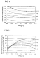
- Fig. 4 is a graph showing the relationship between the total splice loss ⁇ sp_total of one span of an optical transmission fiber 40 and the average value W of the mode field diameter (MFD) of the optical transmission fiber, where the number N of splice points is used as a parameter.
- the total splice loss ⁇ sp_total can be obtained from Formula (7).
- the axial misalignment width d was 0.35 ⁇ m.
- the total splice loss ⁇ sp_total can be made 1.5 dB or less, which is smaller than the case where the average value W of the mode field diameter of the optical transmission fiber 42 is 10.5 ⁇ m (the mode field diameter of SSMF).
- Fig. 5 is a graph showing the relationship between the average value W of the mode field diameter (MFD) of the optical transmission fiber and the improvement amount of total splice loss ⁇ sp_total of one span of the optical fiber transmission line on the basis of SSMF having a mode field diameter of 10.5 ⁇ m, where the number N of splice points is used as a parameter.
- the average value W of the mode field diameter of the optical transmission fiber 42 By setting the average value W of the mode field diameter of the optical transmission fiber 42 to 11.0 ⁇ 12.0 ⁇ m, the splice loss ⁇ sp_total can be reduced as compared with the case where the SSMF is used.
- ⁇ sp_total total splice loss
- ⁇ fiber is attenuation of an optical fiber
- L span length.
- Example 1 40 11.5 0.71 0.017 0.170 14.3
- Example 2 40 12.3 0.77 0.018 0.170 14.4
- Example 3 40 12.3 0.77 0.018 0.164 13.9
- Example 4 40 12.3 0.77 0.018 0.175 14.8
- Example 5 60 11.0 1.05 0.017 0.170 14.7
- Example 6 60 11.6 1.01 0.017 0.170 14.6
- Example 7 60 11.6 1.01 0.017 0.164 14.1
- Example 8 60 11.6 1.01 0.017 0.175 15.0
- Example 9 80 10.5 1.40 0.017 0.170 15.0
- Example 10 80 12.0 1.30 0.016 0.170 14.9
- Example 11 80 12.0 1.30 0.016 0.164 14.4
- Example 12 80 12.0 1.30 0.016 0.175 15.3 Comparative example 1 40
- the span loss ⁇ span becomes 14.9 dB, enabling an improvement of 1.7 dB as compared with the case where the SSMF is used.
- the bend loss of an optical transmission fiber 42 needs to be low, since the fiber is bent to store its extra length portion.
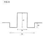
- the optical transmission fiber 42 may have W-type index profile in which a depressed region of low refractive index is provided between the central core and a clad as shown in Fig. 6 .
- Fig. 7 is a table showing design examples of an optical fiber having a W-type index profile.
- the optical transmission fiber 42 may have a ring core index profile in which a depressed region of low refractive index is provided at the core central part as shown in Fig. 8 .
- Fig. 9 is a table showing design examples of an optical fiber having a ring core index profile. In any of the cases, it is possible to have low bend loss property.
- the design method of the optical fiber transmission line 40 is as follows. First, transmission optical fibers 42 are mutually fusion-spliced using a fusion splicer, and the splice loss ⁇ of the splice point concerned is measured, and the axial misalignment width d is estimated from Formula (4) on the basis of the splice loss ⁇ acquired by the measurement. Next, the cable unit length is determined, and the number N of splice points is sought on the basis of the cable unit length thus determined and the span length. Next, the average value W of mode field diameter of the optical transmission fiber 42 in which the total splice loss ⁇ sp_total is minimized is calculated using Formula (8). And then, the total splice loss ⁇ sp_total in one span of the optical fiber transmission line 40 is calculated using Formula (7).
Landscapes
- Physics & Mathematics (AREA)
- General Physics & Mathematics (AREA)
- Optics & Photonics (AREA)
- Electromagnetism (AREA)
- Engineering & Computer Science (AREA)
- Computer Networks & Wireless Communication (AREA)
- Signal Processing (AREA)
- Optical Communication System (AREA)
- Mechanical Coupling Of Light Guides (AREA)
- Optical Fibers, Optical Fiber Cores, And Optical Fiber Bundles (AREA)
Abstract
Description
- The present invention relates to an optical fiber transmission line.
- Japanese Patent Application Laid-Open No.
2003-309520 Patent Document 1, it is mentioned that a splice point exists at every 1 km or so, thereby causing splice loss in an optical fiber transmission line. Also, it is indicated that the repeater interval is usually 40 km or 80 km and that the repeater interval of 80 km or more is preferable where possible, because the link cost for an interval of 40 km would be two times as much as the link cost for an interval of 80 km. - International Publication No.
2009-107260 Patent Document 2, it is indicated that in the case of optical fiber cables installed at present as a terrestrial transmission line in Japan, the span between optical transmission devices is 80 km and a splice point exists at every 2 km on the average. It is also stated that in the case of optical fibers having a large mode field diameter, even if an axial misalignment occurs when the fibers of the same kind are fusion spliced, the splice loss due to splicing is small, since the axial misalignment has relatively small influence on the splice loss because the ratio of the axial misalignment relative to the size of the mode field diameter is small. - Y. Yamamoto, et al, OECC2011, pp.241-244 (2011) (Non-patent Literature 1) indicates that an optical transmission fiber is connected to a pigtail of apparatus, such as an optical fiber amplifier provided in a repeater of an optical fiber communications system. In many cases, the pigtail of apparatus is a standard single mode optical fiber (SSMF) based on International standard ITU-T G. 652.
- An object of the present invention is to provide an optical fiber transmission line in which the total splice loss per span can be made smaller.
- An optical fiber transmission line according to the present invention is used for a span between two repeaters and includes (N+1) number of optical transmission fibers of the same kind, wherein (N+1) number of the optical transmission fibers are connected in series between two connection fibers which are provided respectively in the two repeaters, and the value of Formula (1):

- In the optical fiber transmission line of the present invention, the average splice loss per splice point of the span having N number of splice points of transmission fibers mutually connected and two splice points connecting a transmission fiber and a single mode fiber may be 0.019 dB or less.
- In the optical fiber transmission line of the present invention, the absolute value of Formula (2):

- In the optical fiber transmission line of the present invention, the average value W of the mode field diameter of each of (N+1) number of the optical transmission fibers may be larger than the average value W' of the mode field diameter of each of the two connection fibers, and may be 11.0 to 12.0 µm.
- In the optical fiber transmission line of the present invention, the bend loss of each of (N+1) number of the optical transmission fibers may be 20 dB/m or less at the bend radius of 10 mm. Each of (N+1) number of the optical transmission fibers may have W-type profile or may have a ring core profile.
- An optical fiber transmission line according to another implementation of the present invention is an optical fiber transmission line used for connection between two repeaters and includes (N+1) number of optical transmission fibers of the same kind, wherein (N+1) number of the optical transmission fibers are connected in series between two connection fibers which are provided respectively in the two repeaters, and the two connection fibers are based on International standard ITU-T G. 652 standards, and the average value W of the mode field diameter of each of (N+1) number of the optical transmission fibers is 11.0 µm to 12.0 µm, the bend loss at a bend radius of 10 mm is 20 dB/m or less, and the number N of splice points is 40 or more and 80 or less.
- The optical fiber transmission line of the present invention can make the total splice loss per span smaller.
-
-
Fig. 1 is a schematic diagram showing an optical fiber communications system. -
Fig. 2 is a schematic diagram showing an optical fiber transmission line. -
Fig. 3 is a graph showing the relationship between the number N of splice points and the average value W of the mode field diameter (MFD) of the optical transmission fiber which minimizes the total splice loss αsp_total of one span of the optical fiber transmission line, where the axial misalignment width d is used as a parameter. -
Fig. 4 is a graph showing the relationship between the total splice loss αsp_total of one span of the optical transmission fiber and the average value W of the mode field diameter (MFD) of the optical transmission fiber, where the number N of splice points is used as a parameter. -
Fig. 5 is a graph showing the relationship between the average value W of the mode field diameter (MFD) of the optical transmission fiber and the improvement amount of total splice loss αsp_total of one span of the optical fiber transmission line on the basis of SSMF having a mode field diameter of 10.5 µm, where the number N of splice points is used as a parameter. -
Fig. 6 is a schematic diagram showing a W-type profile. -
Fig. 7 is a table showing an example of design of the optical fiber having the W-type profile. -
Fig. 8 is a schematic diagram showing a ring core profile. -
Fig. 9 is a table showing an example of design of an optical fiber having the ring core profile. - Generally one span of the optical fiber transmission line has two connection fibers both based on International standard ITU-T G.652 standard and the same kind of (N+1) optical transmission fibers connected in series between the two connection fibers, and splice loss occurs at each splice point. The total splice loss αsp_total of the optical fiber transmission line per span is expressed as

- Total splice loss αsp_total of the optical fiber transmission line per span is dependent on the splice loss αSSMF of the optical connection fibers and the optical transmission fibers, the splice loss αtrans of the optical transmission fibers, and the number N of splice points of the optical transmission fibers. It is possible to reduce the total splice loss αsp_total by lessening the number N of splice points as much as possible (namely, increasing the cable unit length). However, lengthening the cable unit length would become a factor for degrading the workability in the case of conveying or installing the cable. Therefore, in the usual terrestrial optical fiber transmission line, a splice point (connection of the same kind) exists for every about 1 km.
- It is possible to make the total splice loss αsp_total small if the splice loss αSSMF of connecting an optical connection fiber and an optical transmission fiber, as well as the splice loss αtrans of mutually connecting optical transmission fibers, can be made small. However, it is not easy to make both of the splice loss αSSMF and the splice loss αtrans small, and consequently it is not easy to make the total splice loss αsp_total per span small.
- Hereafter, preferred embodiments of the present invention will be described in detail with reference to the accompanying drawings. In explanation of the drawings, the same mark will be given to identical elements, and the overlapping explanation will be omitted.
-
Fig. 1 is a schematic diagram showing an opticalfiber communications system 1. The opticalfiber communications system 1 is equipped with atransmitter 10, areceiver 20, and repeaters 300 - 30M, and optical fiber transmission lines provided between them. The signal light sent out from thetransmitter 10 reaches thereceiver 20 through the repeaters 300 - 30M in order, and is received by thereceiver 20. The repeaters 300 - 30M each have apparatus, such as an optical fiber amplifier. -
Fig. 2 is a schematic diagram showing an opticalfiber transmission line 40.Fig. 2 shows arepeater 30m-1 of the repeaters 300 - 30M, arepeater 30m provided at the next step following therepeater 30m-1, and one span of the opticalfiber transmission line 40 provided between therepeater 30m-1 and therepeater 30m. The opticalfiber transmission line 40 has (N+1) optical transmission fibers 420 - 42N. - The optical connection fiber 410 is an optical fiber on the output side of the
repeater 30m-1. The optical connection fiber 411 is an optical fiber on the input side of therepeater 30m. The optical connection fibers 410 and 411 are single mode optical fibers (SSMF) based on International standard ITU-T G.652. (N+1) number of the optical transmission fibers 420 - 42N are connected in series in order between the two optical connection fibers 410 and 411. The optical connection fiber 410 and theoptical transmission fiber 42o are fusion spliced. Theoptical transmission fiber 42n-1 and theoptical transmission fiber 42n are fusion spliced. Also, theoptical transmission fiber 42N and the optical connection fiber 411 are fusion spliced. Usually, a repeater exists at every about 80 km interval and the optical transmission fibers are fusion spliced at every several kilometers between repeaters. - Generally, the causes of splice loss are classified as follows: gap between end-faces; angular misalignment; axial misalignment; and field distribution mismatch. Supposing the splice loss due to a gap between end-faces and angular misalignment is negligibly small, the splice loss α due to an optical fiber having a mode field diameter W1 and an optical fiber having a mode field diameter W2 is estimated as

- With respect to the connection of two optical fibers of the same kind, Formula (5):


- Therefore, the total splice loss αsp_total in one span of the optical
fiber transmission line 40 is expressed as
- Formula (7) shows that the total splice loss αsp_total can be made small, if the number N of splice points is lessened (namely, the cable unit length is increased). However, increasing the cable unit length will cause the degradation in workability for the conveyance or installation of the cable. Therefore, in the usual terrestrial optical fiber transmission line, a splice point (connection of the same kind) exists at every about 1 km - 2 km.
- The smaller the difference in the respective mode field diameter of the optical connection fiber 41 and the
optical transmission fiber 42, the smaller the splice loss of the optical connection fiber 41 and theoptical transmission fiber 42 becomes. On the other hand, the larger the average value W of the mode field diameter of theoptical transmission fibers 42, the allowable width relative to the axial misalignment becomes larger, resulting in the smaller splice loss due to mutual connection of theoptical fibers 42. Therefore, in the average value W of the mode field diameter of theoptical transmission fiber 42, there is an optimal value capable of minimizing the total splice loss αsp_total in one span of the opticalfiber transmission line 40. The average value W of the mode field diameter of theoptical transmission fiber 42 for minimizing the splice loss αsp_total is a value of W where Formula (8):
-
Fig. 3 is a graph showing the relationship between the number N of splice points and the average value W of the mode field diameter (MFD) of theoptical transmission fiber 42 which can minimize the total splice loss αsp_total in one span of the opticalfiber transmission line 40, whereas the axial misalignment width d is used as a parameter. Here, the respective average value W' of mode field diameter in the optical connection fibers 410 and 411 was set to 10.5 µm. InFig. 3 , the average value W of the mode field diameter of theoptical transmission fiber 42 for minimizing the total splice loss αsp_total can be obtained when the number N of splice points and the axial misalignment width d are determined. - When optical fibers are fusion-spliced by using a common optical fiber fusion splicer, the axial misalignment width d will be about 0.30 µm ∼ 0.35 µm. In the case where the span length is 80 km and a splice point exists at every 1 km, the number N of splice points is 79. In this case, the total splice loss αsp_total in one span of the optical
fiber transmission line 40 can be minimized by using anoptical transmission fiber 42 in which the average value W of the mode field diameter is 11.6 µm ∼ 12.1 µm. - If the number N of splice points are increased, the influence of splice loss due to splicing the same kind of fibers will become dominant, and therefore the average value W of the mode field diameter of the
optical transmission fiber 42 which can minimize the total splice loss αsp_total in one span of opticalfiber transmission line 40 becomes larger. However, if the number N of splice points increases, the total splice loss αsp_total will become larger. If the average value W of the mode field diameter of theoptical transmission fiber 42 is increased too much, the bend loss of theoptical transmission fiber 42 will become larger, and hence it is desirable that the average value W of the mode field diameter of theoptical transmission fiber 42 be 13.0 µm or less. -
Fig. 4 is a graph showing the relationship between the total splice loss αsp_total of one span of anoptical transmission fiber 40 and the average value W of the mode field diameter (MFD) of the optical transmission fiber, where the number N of splice points is used as a parameter. The total splice loss αsp_total can be obtained from Formula (7). Here, the axial misalignment width d was 0.35 µm. By setting the number N of splice points 40 or more and 80 or less and setting the average value W of the mode field diameter of theoptical transmission fiber 42 to 11.0 ∼ 12.0 µm, the total splice loss αsp_total can be made 1.5 dB or less, which is smaller than the case where the average value W of the mode field diameter of theoptical transmission fiber 42 is 10.5 µm (the mode field diameter of SSMF). -
Fig. 5 is a graph showing the relationship between the average value W of the mode field diameter (MFD) of the optical transmission fiber and the improvement amount of total splice loss αsp_total of one span of the optical fiber transmission line on the basis of SSMF having a mode field diameter of 10.5 µm, where the number N of splice points is used as a parameter. By setting the average value W of the mode field diameter of theoptical transmission fiber 42 to 11.0 ∼ 12.0 µm, the splice loss αsp_total can be reduced as compared with the case where the SSMF is used. - The span loss αspan of one span of optical
fiber transmission line 40 can be expressed as
- The following Table shows composition of optical fiber transmission lines in the examples of the invention and comparative examples.
Table Number of splice points MFD µm Total splice loss dB Average splice loss dB/splice point Fiber attenuation dB/km Span loss dB Example 1 40 11.5 0.71 0.017 0.170 14.3 Example 2 40 12.3 0.77 0.018 0.170 14.4 Example 3 40 12.3 0.77 0.018 0.164 13.9 Example 4 40 12.3 0.77 0.018 0.175 14.8 Example 5 60 11.0 1.05 0.017 0.170 14.7 Example 6 60 11.6 1.01 0.017 0.170 14.6 Example 7 60 11.6 1.01 0.017 0.164 14.1 Example 8 60 11.6 1.01 0.017 0.175 15.0 Example 9 80 10.5 1.40 0.017 0.170 15.0 Example 10 80 12.0 1.30 0.016 0.170 14.9 Example 11 80 12.0 1.30 0.016 0.164 14.4 Example 12 80 12.0 1.30 0.016 0.175 15.3 Comparative example 1 40 10.5 0.72 0.017 0.190 15.9 Comparative example 2 60 10.5 1.06 0.017 0.190 16.3 Comparative example 3 80 10.5 1.40 0.017 0.190 16.6 Comparative example 4 100 10.5 1.75 0.017 0.190 17.0 Comparative example 5 40 11.8 0.73 0.017 0.170 14.3 Comparative example 6 60 11.8 1.02 0.016 0.170 14.6 Comparative example 7 80 11.8 1.30 0.016 0.170 14.9 Comparative example 8 100 11.8 1.59 0.016 0.170 15.2 - The average splice loss αsp_ave per splice point of a span having N number of splice points of transmission fibers mutually connected and two splice points connecting a transmission fiber and a single mode fiber, can be expressed by:

- In an actual optical fiber communications system, the bend loss of an
optical transmission fiber 42 needs to be low, since the fiber is bent to store its extra length portion. For example, it is desirable that the bend loss of theoptical transmission fiber 42 bent at a bending radius of 10 mm be 20 dB/m or less at the wavelength of 1550 nm. Theoptical transmission fiber 42 may have W-type index profile in which a depressed region of low refractive index is provided between the central core and a clad as shown inFig. 6 .Fig. 7 is a table showing design examples of an optical fiber having a W-type index profile. Theoptical transmission fiber 42 may have a ring core index profile in which a depressed region of low refractive index is provided at the core central part as shown inFig. 8 .Fig. 9 is a table showing design examples of an optical fiber having a ring core index profile. In any of the cases, it is possible to have low bend loss property. - The design method of the optical
fiber transmission line 40 is as follows. First, transmissionoptical fibers 42 are mutually fusion-spliced using a fusion splicer, and the splice loss α of the splice point concerned is measured, and the axial misalignment width d is estimated from Formula (4) on the basis of the splice loss α acquired by the measurement. Next, the cable unit length is determined, and the number N of splice points is sought on the basis of the cable unit length thus determined and the span length. Next, the average value W of mode field diameter of theoptical transmission fiber 42 in which the total splice loss αsp_total is minimized is calculated using Formula (8). And then, the total splice loss αsp_total in one span of the opticalfiber transmission line 40 is calculated using Formula (7).
Claims (13)
- An optical fiber transmission line used for a span between two repeaters, comprising (N+1) number of optical transmission fibers of the same kind, wherein
(N+1) number of the optical transmission fibers are connected in series between two connection fibers provided respectively in the two repeaters, and
the value of the following formula:
is 1.5 dB or less, wherein the average value of the mode field diameter of each of the two connection fibers is W', the average value of the mode field diameter of each of (N+1) number of the optical transmission fibers is W, and the axial misalignment width at the splice point of the two connection fibers and (N+1) number of the optical transmission fibers is d, - An optical fiber transmission line as set forth in claim 1,
wherein the value of the following formula:
is 1.4 dB or less. - An optical fiber transmission line as set forth in claim 1, wherein the average splice loss αsp_ave per splice point of the span is 0.019 dB or less in the case the span has N number of splice points of transmission fibers mutually connected and two splice points connecting a transmission fiber and a single mode fiber.
- An optical fiber transmission line as set forth in claim 1, wherein the absolute value of the following formula:

is 0.02 or less. - An optical fiber transmission line as set forth in claim 1, wherein N, the number of splice points for connecting (N+1) number of optical transmission fibers, is 40 or more and 80 or less.
- An optical fiber transmission line as set forth in claim 1, wherein the span loss of the optical fiber transmission line is 15 dB or less.
- An optical fiber transmission line as set forth in claim 1, wherein the two connection fibers are based on International standard ITU-T G.652 standard.
- An optical fiber transmission line as set forth in claim 1, wherein the average value W of the mode field diameter of each of (N+1) number of the optical transmission fibers may be larger than the average value W' of the mode field diameter of each of the two connection fibers.
- An optical fiber transmission line as set forth in claim 7, wherein the average value W of the mode field diameter of each of (N+1) number of the optical transmission fibers is 11.0 to 12.0 µm.
- An optical fiber transmission line as set forth in claim 1, wherein the bend loss of each of (N+1) number of the optical transmission fibers is 20 dB/m or less at the bend radius of 10 mm.
- An optical fiber transmission line as set forth in claim 1, wherein each of (N+1) number of the optical transmission fibers has W-type index profile.
- An optical fiber transmission line as set forth in claim 1, wherein each of (N+1) number of the optical transmission fibers has a ring core index profile.
- An optical fiber transmission line comprising (N+1) number of optical transmission fibers of the same kind and used for connection between two repeaters, wherein (N+1) number of the optical transmission fibers are connected in series between two connection fibers provided respectively in the two repeaters, the two connection fibers being based on International standard ITU-T G.652 standard; the average value W of the mode field diameter of each of (N+1) number of the optical transmission fibers is 11.0 to 12.0 µm; the bend loss thereof is 20 dB/m or less at the bend radius of 10 mm; and the number N of splice points for connecting (N+1) number of the optical transmission fibers is 40 or more and 80 or less.
Applications Claiming Priority (1)
| Application Number | Priority Date | Filing Date | Title |
|---|---|---|---|
| JP2013182997 | 2013-09-04 |
Publications (1)
| Publication Number | Publication Date |
|---|---|
| EP2846177A1 true EP2846177A1 (en) | 2015-03-11 |
Family
ID=51483254
Family Applications (1)
| Application Number | Title | Priority Date | Filing Date |
|---|---|---|---|
| EP14183348.3A Withdrawn EP2846177A1 (en) | 2013-09-04 | 2014-09-03 | Optical fiber transmission line |
Country Status (4)
| Country | Link |
|---|---|
| US (1) | US9385813B2 (en) |
| EP (1) | EP2846177A1 (en) |
| JP (1) | JP2015072466A (en) |
| CN (1) | CN104422986A (en) |
Families Citing this family (2)
| Publication number | Priority date | Publication date | Assignee | Title |
|---|---|---|---|---|
| JP6486148B2 (en) | 2015-02-27 | 2019-03-20 | キヤノン株式会社 | Image forming apparatus and cartridge |
| CN106559795B (en) | 2015-09-25 | 2022-07-29 | 中兴通讯股份有限公司 | Method and device for determining LBT mode and method for realizing LBT mode switching |
Citations (4)
| Publication number | Priority date | Publication date | Assignee | Title |
|---|---|---|---|---|
| JP2003309520A (en) | 2002-04-16 | 2003-10-31 | Toshiba Corp | Optical communication system |
| EP1576400A1 (en) * | 2002-12-24 | 2005-09-21 | Pirelli & C. S.p.A. | Optical fibre having low splice loss and method for making it |
| JP2009107260A (en) | 2007-10-31 | 2009-05-21 | Toppan Printing Co Ltd | Concealed image laminate, concealed image sheet using the same, and verification method thereof |
| US20090263091A1 (en) * | 2008-02-29 | 2009-10-22 | The Furukawa Electric Co., Ltd. | Optical fiber |
Family Cites Families (6)
| Publication number | Priority date | Publication date | Assignee | Title |
|---|---|---|---|---|
| CA2337013A1 (en) * | 1998-07-14 | 2000-01-27 | Corning Incorporated | Single mode optical waveguide |
| JP2000275469A (en) * | 1999-03-29 | 2000-10-06 | Fujikura Ltd | Optical fiber fusion splicing method |
| US6633712B2 (en) * | 2001-03-16 | 2003-10-14 | Sowilo Networks, Inc. | Method and system for dispersion maps and enhanced distributed gain effect in long haul telecommunications |
| JP4430058B2 (en) * | 2006-10-13 | 2010-03-10 | 古河電気工業株式会社 | Fusion splicer and fusion splicer control method |
| US8655133B2 (en) * | 2010-02-26 | 2014-02-18 | Sumitomo Electric Industries, Ltd. | Optical fiber and optical communication system including same |
| CN102823159A (en) * | 2010-03-26 | 2012-12-12 | 康宁股份有限公司 | Low nonlinearity long haul optical transmission system |
-
2014
- 2014-09-02 JP JP2014177918A patent/JP2015072466A/en active Pending
- 2014-09-03 US US14/475,840 patent/US9385813B2/en active Active
- 2014-09-03 EP EP14183348.3A patent/EP2846177A1/en not_active Withdrawn
- 2014-09-04 CN CN201410449835.5A patent/CN104422986A/en active Pending
Patent Citations (4)
| Publication number | Priority date | Publication date | Assignee | Title |
|---|---|---|---|---|
| JP2003309520A (en) | 2002-04-16 | 2003-10-31 | Toshiba Corp | Optical communication system |
| EP1576400A1 (en) * | 2002-12-24 | 2005-09-21 | Pirelli & C. S.p.A. | Optical fibre having low splice loss and method for making it |
| JP2009107260A (en) | 2007-10-31 | 2009-05-21 | Toppan Printing Co Ltd | Concealed image laminate, concealed image sheet using the same, and verification method thereof |
| US20090263091A1 (en) * | 2008-02-29 | 2009-10-22 | The Furukawa Electric Co., Ltd. | Optical fiber |
Non-Patent Citations (2)
| Title |
|---|
| ANDREW D YABLON: "Optical Fiber Fusion Splicing", PROQUEST EBRARY. WEB, 1 January 2005 (2005-01-01), pages 108 - 115, XP055248441, Retrieved from the Internet <URL:https://ebookcentral.proquest.com/lib/epo-ebooks/> [retrieved on 20160208] * |
| Y. YAMAMOTO ET AL., OECC201, vol. 1, 2011, pages 241 - 244 |
Also Published As
| Publication number | Publication date |
|---|---|
| JP2015072466A (en) | 2015-04-16 |
| CN104422986A (en) | 2015-03-18 |
| US9385813B2 (en) | 2016-07-05 |
| US20150063824A1 (en) | 2015-03-05 |
Similar Documents
| Publication | Publication Date | Title |
|---|---|---|
| EP1338102B1 (en) | Optical fiber for to-the-home distribution networks | |
| EP3414605B1 (en) | Few mode optical fibers for mode division multiplexing | |
| EP2362252B1 (en) | Optical fiber and optical communication system including same | |
| EP1149479B1 (en) | Optical system and method having low loss and non-linear effects | |
| EP2908160A1 (en) | Optical fiber | |
| EP2562571A2 (en) | Optical fiber | |
| JP3912009B2 (en) | Dispersion compensating fiber | |
| EP0866574A1 (en) | Dispersion compensating optical fiber, and communication system comprising the same | |
| US7440662B2 (en) | Compensating fiber for cumulated chromatic dispersion and chromatic dispersion slope | |
| EP2639606A2 (en) | Gradient-index multimode optical fibers for optical fiber connectors | |
| EP2833174A1 (en) | Optical fiber and optical transmission system | |
| EP1486805B1 (en) | Large-effective-area inverse dispersion compensating fiber | |
| AU757249B2 (en) | Dispersion compensation module | |
| US6421484B2 (en) | Optical fiber transmission line and optical cable including the same | |
| JPWO1999030445A1 (en) | Dispersion Compensation Module | |
| US9385813B2 (en) | Optical fiber transmission line | |
| US20030147610A1 (en) | Optical fiber, optical transmission line and optical communications system | |
| US6724964B2 (en) | Optical waveguide exhibiting strongly positive dispersion, and system utilizing same | |
| US6907172B2 (en) | Optical transmission line and optical communication system | |
| JP2001215346A (en) | Optical transmission line and optical transmission system | |
| EP1279980A1 (en) | Dispersion compensating optical fiber ribbon | |
| EP1374454B1 (en) | Optical transmission line | |
| EP1259840B1 (en) | Optical fiber for wdm transmission | |
| US9036998B2 (en) | Long-haul undersea transmission system and fiber | |
| JP2002277673A (en) | Optical fiber transmission line |
Legal Events
| Date | Code | Title | Description |
|---|---|---|---|
| 17P | Request for examination filed |
Effective date: 20140903 |
|
| AK | Designated contracting states |
Kind code of ref document: A1 Designated state(s): AL AT BE BG CH CY CZ DE DK EE ES FI FR GB GR HR HU IE IS IT LI LT LU LV MC MK MT NL NO PL PT RO RS SE SI SK SM TR |
|
| AX | Request for extension of the european patent |
Extension state: BA ME |
|
| PUAI | Public reference made under article 153(3) epc to a published international application that has entered the european phase |
Free format text: ORIGINAL CODE: 0009012 |
|
| R17P | Request for examination filed (corrected) |
Effective date: 20150910 |
|
| RBV | Designated contracting states (corrected) |
Designated state(s): AL AT BE BG CH CY CZ DE DK EE ES FI FR GB GR HR HU IE IS IT LI LT LU LV MC MK MT NL NO PL PT RO RS SE SI SK SM TR |
|
| 17Q | First examination report despatched |
Effective date: 20160301 |
|
| STAA | Information on the status of an ep patent application or granted ep patent |
Free format text: STATUS: THE APPLICATION IS DEEMED TO BE WITHDRAWN |
|
| 18D | Application deemed to be withdrawn |
Effective date: 20170419 |