EP2845993A1 - Couplage de tiges de forage à transmission d'énergie efficace - Google Patents
Couplage de tiges de forage à transmission d'énergie efficace Download PDFInfo
- Publication number
- EP2845993A1 EP2845993A1 EP13183533.2A EP13183533A EP2845993A1 EP 2845993 A1 EP2845993 A1 EP 2845993A1 EP 13183533 A EP13183533 A EP 13183533A EP 2845993 A1 EP2845993 A1 EP 2845993A1
- Authority
- EP
- European Patent Office
- Prior art keywords
- drill string
- male
- female
- outside diameter
- axial length
- Prior art date
- Legal status (The legal status is an assumption and is not a legal conclusion. Google has not performed a legal analysis and makes no representation as to the accuracy of the status listed.)
- Granted
Links
- 230000008878 coupling Effects 0.000 title claims abstract description 60
- 238000010168 coupling process Methods 0.000 title claims abstract description 60
- 238000005859 coupling reaction Methods 0.000 title claims abstract description 60
- 230000005540 biological transmission Effects 0.000 title abstract description 17
- 230000004323 axial length Effects 0.000 claims abstract description 32
- 238000005553 drilling Methods 0.000 abstract description 5
- 238000009527 percussion Methods 0.000 abstract description 2
- 230000035939 shock Effects 0.000 description 11
- 238000005452 bending Methods 0.000 description 4
- 238000000034 method Methods 0.000 description 3
- 239000011435 rock Substances 0.000 description 3
- 238000004088 simulation Methods 0.000 description 2
- 230000009286 beneficial effect Effects 0.000 description 1
- 238000004364 calculation method Methods 0.000 description 1
- 230000001186 cumulative effect Effects 0.000 description 1
- 230000007423 decrease Effects 0.000 description 1
- 230000001419 dependent effect Effects 0.000 description 1
- 239000012530 fluid Substances 0.000 description 1
- 238000011010 flushing procedure Methods 0.000 description 1
- 238000004904 shortening Methods 0.000 description 1
- 230000007704 transition Effects 0.000 description 1
Images


Classifications
-
- E—FIXED CONSTRUCTIONS
- E21—EARTH OR ROCK DRILLING; MINING
- E21B—EARTH OR ROCK DRILLING; OBTAINING OIL, GAS, WATER, SOLUBLE OR MELTABLE MATERIALS OR A SLURRY OF MINERALS FROM WELLS
- E21B17/00—Drilling rods or pipes; Flexible drill strings; Kellies; Drill collars; Sucker rods; Cables; Casings; Tubings
- E21B17/02—Couplings; joints
- E21B17/04—Couplings; joints between rod or the like and bit or between rod and rod or the like
- E21B17/042—Threaded
-
- E—FIXED CONSTRUCTIONS
- E21—EARTH OR ROCK DRILLING; MINING
- E21B—EARTH OR ROCK DRILLING; OBTAINING OIL, GAS, WATER, SOLUBLE OR MELTABLE MATERIALS OR A SLURRY OF MINERALS FROM WELLS
- E21B17/00—Drilling rods or pipes; Flexible drill strings; Kellies; Drill collars; Sucker rods; Cables; Casings; Tubings
- E21B17/02—Couplings; joints
- E21B17/04—Couplings; joints between rod or the like and bit or between rod and rod or the like
- E21B17/042—Threaded
- E21B17/0426—Threaded with a threaded cylindrical portion, e.g. for percussion rods
-
- F—MECHANICAL ENGINEERING; LIGHTING; HEATING; WEAPONS; BLASTING
- F16—ENGINEERING ELEMENTS AND UNITS; GENERAL MEASURES FOR PRODUCING AND MAINTAINING EFFECTIVE FUNCTIONING OF MACHINES OR INSTALLATIONS; THERMAL INSULATION IN GENERAL
- F16D—COUPLINGS FOR TRANSMITTING ROTATION; CLUTCHES; BRAKES
- F16D1/00—Couplings for rigidly connecting two coaxial shafts or other movable machine elements
- F16D1/02—Couplings for rigidly connecting two coaxial shafts or other movable machine elements for connecting two abutting shafts or the like
-
- F—MECHANICAL ENGINEERING; LIGHTING; HEATING; WEAPONS; BLASTING
- F16—ENGINEERING ELEMENTS AND UNITS; GENERAL MEASURES FOR PRODUCING AND MAINTAINING EFFECTIVE FUNCTIONING OF MACHINES OR INSTALLATIONS; THERMAL INSULATION IN GENERAL
- F16L—PIPES; JOINTS OR FITTINGS FOR PIPES; SUPPORTS FOR PIPES, CABLES OR PROTECTIVE TUBING; MEANS FOR THERMAL INSULATION IN GENERAL
- F16L15/00—Screw-threaded joints; Forms of screw-threads for such joints
- F16L15/06—Screw-threaded joints; Forms of screw-threads for such joints characterised by the shape of the screw-thread
-
- F—MECHANICAL ENGINEERING; LIGHTING; HEATING; WEAPONS; BLASTING
- F16—ENGINEERING ELEMENTS AND UNITS; GENERAL MEASURES FOR PRODUCING AND MAINTAINING EFFECTIVE FUNCTIONING OF MACHINES OR INSTALLATIONS; THERMAL INSULATION IN GENERAL
- F16L—PIPES; JOINTS OR FITTINGS FOR PIPES; SUPPORTS FOR PIPES, CABLES OR PROTECTIVE TUBING; MEANS FOR THERMAL INSULATION IN GENERAL
- F16L15/00—Screw-threaded joints; Forms of screw-threads for such joints
- F16L15/08—Screw-threaded joints; Forms of screw-threads for such joints with supplementary elements
Definitions
- the present invention relates to a drill string coupling for connecting individual elongate drill string members and in particular, although not exclusively, to an energy transmission efficient coupling that minimises impedance mismatch between the coupled members.
- Percussive drilling is an established technique designed to break rock by impact forces transferred from the drill string to the drill bit at the bottom of a borehole.
- the energy required to break the rock is generated by a pneumatic or hydraulic actuated hammer mounted at a ground level end of the string.
- a pressured piston is driven forward to contact a shank adaptor at the end of the string such that kinetic energy of the piston is translated to a stress (or shock) wave that travels through the drill string to the drill bit mounted at the furthest end of the string.
- a stress (or shock) wave that travels through the drill string to the drill bit mounted at the furthest end of the string.
- the objectives are achieved by providing a drill string and in particular a threaded coupling for connecting drill string members in which male and female coupling parts are adapted specifically to maximise energy transmission in the longitudinal axis direction of the drill string.
- a drill string comprising: a first elongate drill string member having a main section and a male end; a second elongate drill string member having a main section and a female end; the male and female ends having respective threads to enable the male end to be secured inside the female end such that an axial length of the male and female ends overlap axially; characterised in that : an axial length of the overlap is less than an outside diameter of the female end.
- the impedance mismatch is reduced accordingly.
- the relationship between the outside diameter of the female end and the axial length of the male end has been found to influence significantly the energy transmission efficiency of the coupling.
- shortening the male coupling part also reduces internally generated stresses in the coupling.
- an incoming compressive stress wave generates tensile stress in the male end as the stress wave reaches the 'free' end face of the male connector. Effectively the male end is forced to elongate axially forward since there is no 'stop' at the free end. This creates tensile stress at the junction between the drill rod main length and the male connector.
- this tensile stress is dependent on the length, and in particular, the mass of the male end (the longer/heavier the male end, the higher the tensile stress). If unregulated, this tensile stress causes breakage at the drill rod main length-male end junction and effectively limits the maximum impact amplitude.
- the present configuration having a relatively 'shorter' male part is configured to minimise tensile stresses, increase the lifetime of the drill rod and enable 'higher' impact amplitudes (that are desired for maximum rock breaking performance at the borehole bottom).
- ' threads ' refers to a helical ridge and groove extending axially along a length portion of the male and female end. This term encompasses a thread having a single axially extending helical ridge and a plurality of helical ridges having a plurality of entries on the thread.
- the helical threads at the male and/or female ends comprise between two to four complete helical turns. This configuration allows the drill string members to be coupled together conveniently and to avoid any axial slippage or decoupling due to undesirable rotation about a longitudinal axis extending through the drill string members.
- the male end comprises an axial length of between 100 to 150 mm.
- the axial length of the male end is defined as the axial distance between the endmost part of the drill string member (at the male end) and the region where the main section (or a radially extending shoulder that projects from the main section) decreases representing a transition region between the main section and the male end.
- the male end axial length is in a range 110 to 140 mm or 120 to 130 mm.
- a wall thickness of the female end is greater than a wall thickness of the male end at the overlap. This configuration is advantageous to provide sufficient strength at the region of the coupling overlap to withstand the stresses resultant from the shock wave and bending movements that occur along the length of the drill string in use.
- a radial position of the peak of each respective thread turn (at a different axial position along the length of the thread) of the male and female ends is substantially uniform, such that an alignment of or a bisecting line through each peak is substantially parallel to a longitudinal axis of the first and second members. Accordingly, an alignment of the overlap is substantially parallel to the longitudinal axis.
- Such an arrangement is beneficial to reduce the impedance mismatch and provide efficient transfer of the shock wave through the coupling region.
- the male end is hollow and an inside diameter of the male end is equal to an inside diameter of the main length section.
- the respective size of the inside diameters is configured to avoid restriction of a flow of flushing fluids through the drill string.
- an inside diameter of the main section increases at the junction with the female end.
- the enlarge diameter coupling region is advantageous to provide bending stiffness of the string to withstand large bending moments and non-symmetrical forces acting on the string.
- an outside diameter of the female end is greater than an outside diameter of the main section.
- the present drill string and threaded coupling arrangement is suitable for both ' shoulder contact ' and ' bottom contact ' coupling configurations.
- the term ' shoulder contact ' refers to a configuration in which the threaded male end is terminated at its axially innermost region by a radially projecting shoulder that is configured to abut against an axially endmost region of the female end of a neighbouring drill string member.
- the term ' bottom contact ' refers to a coupling in which the endmost region of the male end abuts against an axially innermost internal end of the female sleeve.
- the drill rod may comprise a shoulder projecting radially from one end of the main section at the region of the male end wherein an outside diameter of the shoulder is greater than an outside diameter of the main section.
- the male end comprises a non-threaded shank positioned axially intermediate the main section and a region of the male end comprising the threads.
- an axial length of the non-threaded shank is substantially equal to an axial length over which the threads extend along the male end.
- an outside diameter of the non-threaded shank is substantially equal to an outside diameter of the main section.
- a threaded coupling for connecting drill string members to form a drill string
- the coupling comprising: a male end having an axial length and an outside diameter; a hollow female end having an axial length and an outside diameter, the outside diameter of the female end being greater than the outside diameter of the male end; the male and female ends having respective threads to enable the male end to be secured inside the female end such that at least a part of the axial length of the male and female ends overlap axially to form a coupling; characterised in that : an axial length of the overlap is less than the outside diameter of the female end.
- a stress or shock wave that is transmitted through a drill string from the initial impact piston comprises a generally rectangular shape profile having a wavelength that is approximately twice the length of the piston and a wave amplitude that depends of the speed of the piston on impact and the relationship between the cross sectional area of the piston and the drill rod.
- the shock wave loses a significant percentage of its energy as it is transmitted through the coupling region of the drill string. Additionally, it is well established that differences in the cross sectional area between the male and female threaded couplings contribute to the impedance mismatch in the drill system.
- the subject invention provides an energy transmission efficient coupling that minimises the length of the impedance mismatch by minimising an axial length of the overlap region between the threaded male and female coupling ends of the drill string rods.
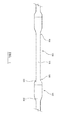
- a drill string comprises a plurality of interconnected drill string rods 100.
- Each rod 100 comprises a main length section 101 having a first end 105 and a second end 106.
- An outside diameter of the main length section 101 increases at each end 105, 106 to form a radially flared end coupling region 103, 104 respectively.
- a part of each coupling end 103, 104 comprises a threaded portion to allow the ends 103, 104 to engage one another and form a secure threaded coupling 102 to interconnect a plurality of rods 100 to form the drill string.
- Figure 2 illustrates the coupling region 102 of figure 1 in more detail.
- male end 103 projects axially from main section end 106.
- An annular shoulder 203 projects radially from end 106 such that a diameter of an outer surface 202 of shoulder 203 is greater than a diameter of main section 101 at external surface 219.
- the radially outermost region of shoulder 203 is bordered at a first side by a concave tapered surface 220 and at a second side by an annular abutment surface 201 aligned perpendicular to a longitudinal axis 221 extending through the rods 100.
- Male end 103 comprises a shank 204 aligned substantially parallel with axis 221 and having an outer surface 215 aligned substantially parallel to axis 221.
- Shank 204 is terminated at its endmost region by a threaded section indicated generally by reference 205.
- section 205 corresponds approximately in shape and configuration to shank 204 but comprises external facing threads extending axially between an annular end surface 208 (of male coupling 103) and shank 204.
- the thread is formed from two helices having 1.5 helical turns between shank 204 and end surface 208.
- An external shape profile of threaded section 205 therefore comprises a series of ridges 206 and troughs 207 when the male end is viewed externally from one side for example.
- the outside diameter of the threaded section 205, corresponding to an axial and radial position of the peak of each ridge 206 is approximately equal to an outside diameter of main length section 101. Additionally, an outside diameter of shank surface 215 is approximately equal to the outside diameter of the axial and radial position corresponding to each ridge 206.
- Male end 103 is hollow so as to comprise an internal surface 209 that is aligned parallel or coaxially with an internal surface 210 of main length section 101.
- Female end 104 comprises a generally hollow sleeve-like configuration that is generally flared radially outward relative to main length section 101 and is coupled to section 101 via a radially tapered region 217.
- Sleeve 104 comprises an external surface 218 and a corresponding internal surface 216.
- An axially endmost region 211 of sleeve 104 comprises internal surface 216 aligned substantially parallel with axis 221.
- a threaded region 212 is positioned axially between endmost region 211 and flared region 217 and comprises threads formed at internal surface 216.
- the threads of the female end 104 also comprise 1.5 complete helical turns to define a helically extending ridge 213 and trough 214, with ridge 213 projecting radially inward towards the trough 207 of male end 103.
- male end 103 is fully engaged within the sleeve-like configuration of the female end 104 when an endmost annular surface 200 of end region 211 abuts against the annular abutment surface 201 at the side of shoulder 203.
- the present implementation is therefore described by way of example with reference to a ' shoulder contact ' configuration.
- the present invention may be equally implemented in a ' bottom contact ' configuration in which male end surface 208 would abut against a cooperating abutment surface provided at a part of flared region 217.
- the subject invention comprises a coupling region 102 that is optimised to minimise the length of any impedance mismatch between the coupled rods 100.
- a length L that represents the axial length of the overlap between the male end 103 and the female end 104 is maintained to a minimum without compromising coupling strength and the ability of the drill string to withstand stresses and stress concentrations within the coupling region 102 resulting from tensile and bending forces.
- male and female ends 103, 104 are optimised such that the axial length L, corresponding to the axial distance between male end surface 208 and female end surface 200, is less than an outside diameter D of the female sleeve 104 corresponding to outer surface 218.
- an axial length of the male spigot portion comprising a combined axial length of the shank 204 and threaded section 205 is less than outside diameter D of the sleeve 104.
- Such a configuration minimises the mass of male end 103 and accordingly the tensile stress created at the junction between end 103 and shoulder 203 which would otherwise lead to breakage of the shank 204 away from the abutment surface 201.
- the present coupling is therefore configured to withstand significantly higher incident compressive shock waves resultant from higher impact amplitudes.
- each threaded sections 205, 212 may comprise a single helix having between two to four complete helical turns extending along the full axial length of threaded sections 205, 212.
- both sets of rods comprised a total rod length of 3 m having a main length section 101 with an outside diameter of 110 mm and an inner diameter of 80 mm.
- the outside diameter D of each female coupling 104 was 140 mm.
- the axial length of the male spigot 103 (including shank 204 and threaded section 205) was 125 mm.
- a corresponding axial length of a conventional test male spigot was 190 mm corresponding to distance L of figure 2 . Accordingly, the ' overlap ' region of the two rod types is represented by distance L of figure 2 .
- FIG. 4 illustrates the cumulative effect of sequential coupling regions 102 on the total energy transmission efficiency.
- figure 4 illustrates the system efficiency for four different coupling configurations in which distance L is variable corresponding to a system with 99.5% efficiency 400; 99% efficiency 401; 98% efficiency 402 (the subject invention) and 96% efficiency 403 (of the simulated prior art coupling detailed above).
- distance L is variable corresponding to a system with 99.5% efficiency 400; 99% efficiency 401; 98% efficiency 402 (the subject invention) and 96% efficiency 403 (of the simulated prior art coupling detailed above).
- progression through forty couplings provides an energy efficiency transmission increase of nearly 30%.
Landscapes
- Engineering & Computer Science (AREA)
- Life Sciences & Earth Sciences (AREA)
- Geology (AREA)
- Mining & Mineral Resources (AREA)
- Mechanical Engineering (AREA)
- General Engineering & Computer Science (AREA)
- Physics & Mathematics (AREA)
- Environmental & Geological Engineering (AREA)
- Fluid Mechanics (AREA)
- General Life Sciences & Earth Sciences (AREA)
- Geochemistry & Mineralogy (AREA)
- Earth Drilling (AREA)
Priority Applications (12)
| Application Number | Priority Date | Filing Date | Title |
|---|---|---|---|
| PL13183533T PL2845993T3 (pl) | 2013-09-09 | 2013-09-09 | Łącznik udarowej rury wiertniczej wydajny w przenoszeniu energii |
| EP13183533.2A EP2845993B1 (fr) | 2013-09-09 | 2013-09-09 | Couplage de tiges de forage à percussion à transmission d'énergie efficace |
| AU2014317321A AU2014317321B2 (en) | 2013-09-09 | 2014-08-25 | Energy transmission efficient drill string coupling |
| PE2016000306A PE20160334A1 (es) | 2013-09-09 | 2014-08-25 | Acoplamiento de sarta de perforacion eficaz en cuanto a transmision de energia |
| KR1020167008301A KR20160051825A (ko) | 2013-09-09 | 2014-08-25 | 에너지 전송 효율적인 드릴 스트링 커플링 |
| CA2922454A CA2922454A1 (fr) | 2013-09-09 | 2014-08-25 | Accouplement de train de tiges de forage a rendement de transmission d'energie |
| US14/916,774 US10190372B2 (en) | 2013-09-09 | 2014-08-25 | Energy transmission efficient drill string coupling |
| PCT/EP2014/067979 WO2015032642A2 (fr) | 2013-09-09 | 2014-08-25 | Accouplement de train de tiges de forage à rendement de transmission d'énergie |
| MX2016003021A MX371081B (es) | 2013-09-09 | 2014-08-25 | Acoplamiento de sarta de perforación eficaz en cuanto a transmisión de energía. |
| RU2016113358A RU2667552C2 (ru) | 2013-09-09 | 2014-08-25 | Замок для труб бурильной колонны с высоким кпд передачи энергии |
| CN201480049781.1A CN105637168B (zh) | 2013-09-09 | 2014-08-25 | 能量高效传递的钻柱联接器 |
| CL2016000520A CL2016000520A1 (es) | 2013-09-09 | 2016-03-07 | Acoplamiento de sarta de perforación eficaz en cuanto a transmisión de energía |
Applications Claiming Priority (1)
| Application Number | Priority Date | Filing Date | Title |
|---|---|---|---|
| EP13183533.2A EP2845993B1 (fr) | 2013-09-09 | 2013-09-09 | Couplage de tiges de forage à percussion à transmission d'énergie efficace |
Publications (2)
| Publication Number | Publication Date |
|---|---|
| EP2845993A1 true EP2845993A1 (fr) | 2015-03-11 |
| EP2845993B1 EP2845993B1 (fr) | 2018-01-10 |
Family
ID=49150787
Family Applications (1)
| Application Number | Title | Priority Date | Filing Date |
|---|---|---|---|
| EP13183533.2A Not-in-force EP2845993B1 (fr) | 2013-09-09 | 2013-09-09 | Couplage de tiges de forage à percussion à transmission d'énergie efficace |
Country Status (12)
| Country | Link |
|---|---|
| US (1) | US10190372B2 (fr) |
| EP (1) | EP2845993B1 (fr) |
| KR (1) | KR20160051825A (fr) |
| CN (1) | CN105637168B (fr) |
| AU (1) | AU2014317321B2 (fr) |
| CA (1) | CA2922454A1 (fr) |
| CL (1) | CL2016000520A1 (fr) |
| MX (1) | MX371081B (fr) |
| PE (1) | PE20160334A1 (fr) |
| PL (1) | PL2845993T3 (fr) |
| RU (1) | RU2667552C2 (fr) |
| WO (1) | WO2015032642A2 (fr) |
Cited By (4)
| Publication number | Priority date | Publication date | Assignee | Title |
|---|---|---|---|---|
| EP3095954A1 (fr) | 2015-05-22 | 2016-11-23 | Sandvik Intellectual Property AB | Tige de forage ou adaptateur de couplage avec un embout renforcé |
| EP3819458A1 (fr) * | 2019-11-08 | 2021-05-12 | Sandvik Mining and Construction Tools AB | Couplage femelle de train de forage à percussion renforcé |
| CN113544355A (zh) * | 2018-12-03 | 2021-10-22 | 山特维克矿山工程机械有限公司 | 用于旋转钻凿的钻柱、螺纹联接和钻杆适配器 |
| WO2023144377A1 (fr) | 2022-01-31 | 2023-08-03 | Sandvik Mining And Construction Tools Ab | Élément de forage |
Families Citing this family (4)
| Publication number | Priority date | Publication date | Assignee | Title |
|---|---|---|---|---|
| US20180100356A1 (en) * | 2016-10-10 | 2018-04-12 | Padley & Venables Limited | Drill Rod |
| CN107504088A (zh) * | 2017-09-28 | 2017-12-22 | 江苏唯侓机器人科技有限公司 | 一种耐磨损联轴器 |
| CN110630644A (zh) * | 2018-06-22 | 2019-12-31 | 益航电子股份有限公司 | 传动轴 |
| PL3712374T3 (pl) * | 2019-03-18 | 2023-01-16 | Sandvik Mining And Construction Tools Ab | Żerdź przewodu wiertniczego |
Citations (4)
| Publication number | Priority date | Publication date | Assignee | Title |
|---|---|---|---|---|
| US6108268A (en) * | 1998-01-12 | 2000-08-22 | The Regents Of The University Of California | Impedance matched joined drill pipe for improved acoustic transmission |
| US6485061B1 (en) | 1996-05-07 | 2002-11-26 | Frank's Casing Crew And Rental Tools, Inc. | Threaded tool joint for connecting large diameter tubulars |
| US20040050592A1 (en) * | 2002-06-27 | 2004-03-18 | Sandvik Ab. | Male portion, drill bit and threaded joint for percussive rock drilling |
| US20060032629A1 (en) | 2002-10-31 | 2006-02-16 | Casper William L | Insertion tube methods and apparatus |
Family Cites Families (31)
| Publication number | Priority date | Publication date | Assignee | Title |
|---|---|---|---|---|
| US201082A (en) * | 1878-03-12 | Improvement in joints for oil-well tools | ||
| US1394791A (en) * | 1920-07-21 | 1921-10-25 | James P Markham Jr | Pipe-coupling |
| US1515617A (en) * | 1922-09-29 | 1924-11-18 | Clarence D Reynolds | Tool joint |
| US1714818A (en) * | 1925-10-07 | 1929-05-28 | Earl A Reed | Hydraulic rotary drill stem |
| US1589781A (en) * | 1925-11-09 | 1926-06-22 | Joseph M Anderson | Rotary tool joint |
| US1637628A (en) * | 1926-11-15 | 1927-08-02 | Edwin C Weisgerber | Tool joint |
| US1918443A (en) * | 1930-07-11 | 1933-07-18 | Lawrence F Baash | Tool joint |
| US2205697A (en) * | 1938-05-06 | 1940-06-25 | Charles C Scharpenberg | Tool joint for well drilling |
| US3080179A (en) * | 1959-10-06 | 1963-03-05 | Huntsinger Associates | Slip engaging portion of drill string formed of increased wall thickness and reduced hardness |
| US3067593A (en) * | 1960-08-29 | 1962-12-11 | American Iron & Machine Works | Integral tool joint drill pipe |
| US3401371A (en) * | 1966-04-27 | 1968-09-10 | Columbia Products Co | Ferrule for connecting antennae together |
| US3537738A (en) | 1968-04-15 | 1970-11-03 | Sandvikens Jernverks Ab | Drill rod for long hole drilling in the ground |
| US3773359A (en) * | 1971-06-24 | 1973-11-20 | Smith International | Intermediate drill stem |
| SU574786A1 (ru) | 1976-06-01 | 1977-09-30 | Харьковское производственное объединение "Радиореле" | Электромагнитное реле и способ его сборки |
| US4509777A (en) * | 1982-11-01 | 1985-04-09 | Dril-Quip Inc. | Weld-on casing connector |
| US4506432A (en) * | 1983-10-03 | 1985-03-26 | Hughes Tool Company | Method of connecting joints of drill pipe |
| SU1574786A1 (ru) * | 1987-06-29 | 1990-06-30 | Институт горного дела им.А.А.Скочинского | Замковое соединение штанг бурового става |
| US4998831A (en) * | 1987-07-15 | 1991-03-12 | Proni Creations Inc. | Force concentrating unitary fitting |
| US5785357A (en) * | 1995-09-22 | 1998-07-28 | Utd, Inc. | Locking joint |
| US6164392A (en) * | 1999-04-26 | 2000-12-26 | Sandvik Ab | Percussive drilling apparatus |
| ES2394032T3 (es) * | 1999-04-30 | 2013-01-15 | Grant Prideco, Inc | Conexión roscada con alta tasa de compresión |
| US6212763B1 (en) * | 1999-06-29 | 2001-04-10 | Frederic M. Newman | Torque-turn system for a three-element sucker rod joint |
| AU4522501A (en) * | 1999-12-10 | 2001-06-18 | Ingersoll-Rand Company | Drill rod having selectively hardened sections |
| SE515195C2 (sv) * | 2000-03-02 | 2001-06-25 | Sandvik Ab | Gängförband och bergborrelement för slående borrning |
| FR2833335B1 (fr) * | 2001-12-07 | 2007-05-18 | Vallourec Mannesmann Oil & Gas | Joint filete tubulaire superieur contenant au moins un element filete avec levre d'extremite |
| SE524322C2 (sv) * | 2002-09-24 | 2004-07-27 | Sandvik Ab | Borrstång och metod för att tillverka denna |
| FR2868146B1 (fr) * | 2004-03-26 | 2009-01-23 | Vallourec Mannesmann Oil Gas F | Joint filete tubulaire resistant aux contraintes de flexion |
| RU2398091C2 (ru) * | 2007-11-16 | 2010-08-27 | Общество с ограниченной ответственностью "Пермское конструкторско-технологическое бюро технического проектирования и организации производства" | Полая насосная штанга |
| CN201301670Y (zh) * | 2008-04-23 | 2009-09-02 | 长年Tm公司 | 双钢冲击钻杆 |
| US8678447B2 (en) * | 2009-06-04 | 2014-03-25 | National Oilwell Varco, L.P. | Drill pipe system |
| US8757671B2 (en) * | 2011-12-02 | 2014-06-24 | Vetco Gray Inc. | Slide actuating tubular connector |
-
2013
- 2013-09-09 EP EP13183533.2A patent/EP2845993B1/fr not_active Not-in-force
- 2013-09-09 PL PL13183533T patent/PL2845993T3/pl unknown
-
2014
- 2014-08-25 MX MX2016003021A patent/MX371081B/es active IP Right Grant
- 2014-08-25 CN CN201480049781.1A patent/CN105637168B/zh not_active Expired - Fee Related
- 2014-08-25 RU RU2016113358A patent/RU2667552C2/ru active
- 2014-08-25 PE PE2016000306A patent/PE20160334A1/es active IP Right Grant
- 2014-08-25 AU AU2014317321A patent/AU2014317321B2/en not_active Ceased
- 2014-08-25 KR KR1020167008301A patent/KR20160051825A/ko not_active Application Discontinuation
- 2014-08-25 CA CA2922454A patent/CA2922454A1/fr not_active Abandoned
- 2014-08-25 US US14/916,774 patent/US10190372B2/en not_active Expired - Fee Related
- 2014-08-25 WO PCT/EP2014/067979 patent/WO2015032642A2/fr active Application Filing
-
2016
- 2016-03-07 CL CL2016000520A patent/CL2016000520A1/es unknown
Patent Citations (4)
| Publication number | Priority date | Publication date | Assignee | Title |
|---|---|---|---|---|
| US6485061B1 (en) | 1996-05-07 | 2002-11-26 | Frank's Casing Crew And Rental Tools, Inc. | Threaded tool joint for connecting large diameter tubulars |
| US6108268A (en) * | 1998-01-12 | 2000-08-22 | The Regents Of The University Of California | Impedance matched joined drill pipe for improved acoustic transmission |
| US20040050592A1 (en) * | 2002-06-27 | 2004-03-18 | Sandvik Ab. | Male portion, drill bit and threaded joint for percussive rock drilling |
| US20060032629A1 (en) | 2002-10-31 | 2006-02-16 | Casper William L | Insertion tube methods and apparatus |
Non-Patent Citations (5)
| Title |
|---|
| "ROTARY SHOULDER HANDBOOK", 1 November 2011 (2011-11-01), pages 1 - 116, XP055097517, Retrieved from the Internet <URL:http://www.nov.com/uploadedFiles/Business_Groups/Grant_Prideco/Drilling_Tubulars/Catalog/D392002466-MKT-001 Rev 02 Rotary Shoulder Handbook RS.pdf> [retrieved on 20140121] * |
| "Tool Joint Dimensional Data", 1 December 2003 (2003-12-01), pages 1 - 3, XP055097521, Retrieved from the Internet <URL:http://www.oilproduction.net/files/casing_drilling/GP_Tool_Joint_Dimensional_Value.pdf> [retrieved on 20140121] * |
| ANONYMOUS: "Drill Rod & Casing Dimensions", 1 December 2012 (2012-12-01), pages 1 - 1, XP055097519, Retrieved from the Internet <URL:http://www.mobiledrill.net/page/drill-rod-and-casing-dimensions> [retrieved on 20140121] * |
| B. LUNDBERG: "Efficiency of percussive drilling with extension rods", INTERNATIONAL JOURNAL OF ROCK MECHANICS AND MINING SCIENCES & GEOMECHANICS ABSTRACTS, vol. 24, no. 4, 1 August 1987 (1987-08-01), pages 213 - 222, XP055097510, ISSN: 0148-9062, DOI: 10.1016/0148-9062(87)90176-8 * |
| E. BECCU ET AL: "Efficiency of percussive drilling of rock with dissipative joints", INTERNATIONAL JOURNAL OF IMPACT ENGINEERING, vol. 9, no. 3, 1 January 1990 (1990-01-01), pages 277 - 287, XP055097507, ISSN: 0734-743X, DOI: 10.1016/0734-743X(90)90003-E * |
Cited By (9)
| Publication number | Priority date | Publication date | Assignee | Title |
|---|---|---|---|---|
| EP3095954A1 (fr) | 2015-05-22 | 2016-11-23 | Sandvik Intellectual Property AB | Tige de forage ou adaptateur de couplage avec un embout renforcé |
| WO2016188862A1 (fr) | 2015-05-22 | 2016-12-01 | Sandvik Intellectual Property Ab | Tige de forage ou adaptateur avec raccord à emboîtement renforcé |
| EP3298229B1 (fr) | 2015-05-22 | 2020-10-14 | Sandvik Intellectual Property AB | Tige de forage ou adaptateur de couplage avec un embout renforcé |
| EP3095954B1 (fr) * | 2015-05-22 | 2024-05-15 | Sandvik Intellectual Property AB | Tige de forage ou adaptateur de couplage avec un embout renforcé |
| CN113544355A (zh) * | 2018-12-03 | 2021-10-22 | 山特维克矿山工程机械有限公司 | 用于旋转钻凿的钻柱、螺纹联接和钻杆适配器 |
| CN113544355B (zh) * | 2018-12-03 | 2024-02-20 | 山特维克矿山工程机械有限公司 | 用于旋转钻凿的钻柱、螺纹联接和钻杆适配器 |
| EP3819458A1 (fr) * | 2019-11-08 | 2021-05-12 | Sandvik Mining and Construction Tools AB | Couplage femelle de train de forage à percussion renforcé |
| WO2021089727A1 (fr) * | 2019-11-08 | 2021-05-14 | Sandvik Mining And Construction Tools Ab | Raccord femelle de train de tiges de forage à percussion renforcé |
| WO2023144377A1 (fr) | 2022-01-31 | 2023-08-03 | Sandvik Mining And Construction Tools Ab | Élément de forage |
Also Published As
| Publication number | Publication date |
|---|---|
| CA2922454A1 (fr) | 2015-03-12 |
| MX2016003021A (es) | 2016-06-10 |
| RU2667552C2 (ru) | 2018-09-21 |
| EP2845993B1 (fr) | 2018-01-10 |
| WO2015032642A3 (fr) | 2015-10-08 |
| MX371081B (es) | 2020-01-16 |
| RU2016113358A (ru) | 2017-10-16 |
| KR20160051825A (ko) | 2016-05-11 |
| CN105637168A (zh) | 2016-06-01 |
| WO2015032642A2 (fr) | 2015-03-12 |
| PE20160334A1 (es) | 2016-05-04 |
| US20160222737A1 (en) | 2016-08-04 |
| CL2016000520A1 (es) | 2016-09-23 |
| US10190372B2 (en) | 2019-01-29 |
| CN105637168B (zh) | 2019-04-09 |
| PL2845993T3 (pl) | 2018-07-31 |
| AU2014317321B2 (en) | 2018-01-18 |
| AU2014317321A1 (en) | 2016-03-10 |
Similar Documents
| Publication | Publication Date | Title |
|---|---|---|
| EP2845993A1 (fr) | Couplage de tiges de forage à transmission d'énergie efficace | |
| EP3298229B1 (fr) | Tige de forage ou adaptateur de couplage avec un embout renforcé | |
| EP2845992B1 (fr) | Train de tiges de forage avec couplage résistant à la flexion | |
| EP2845991B1 (fr) | Tiges de train de forage à couplage à ergot renforcé | |
| EP3023575A1 (fr) | Tige de train de tiges avec épaulement | |
| EP3298228B1 (fr) | Extrémité de couplage filetée pour composant de train de tiges de percussion | |
| EP3048239A1 (fr) | Tige de guidage de forage résistant à une déviation | |
| EP3663506B1 (fr) | Train de tiges, couplage fileté et adaptateur de tige pour forage rotatif |
Legal Events
| Date | Code | Title | Description |
|---|---|---|---|
| 17P | Request for examination filed |
Effective date: 20130909 |
|
| AK | Designated contracting states |
Kind code of ref document: A1 Designated state(s): AL AT BE BG CH CY CZ DE DK EE ES FI FR GB GR HR HU IE IS IT LI LT LU LV MC MK MT NL NO PL PT RO RS SE SI SK SM TR |
|
| AX | Request for extension of the european patent |
Extension state: BA ME |
|
| PUAI | Public reference made under article 153(3) epc to a published international application that has entered the european phase |
Free format text: ORIGINAL CODE: 0009012 |
|
| RBV | Designated contracting states (corrected) |
Designated state(s): AL AT BE BG CH CY CZ DE DK EE ES FI FR GB GR HR HU IE IS IT LI LT LU LV MC MK MT NL NO PL PT RO RS SE SI SK SM TR |
|
| GRAP | Despatch of communication of intention to grant a patent |
Free format text: ORIGINAL CODE: EPIDOSNIGR1 |
|
| INTG | Intention to grant announced |
Effective date: 20170810 |
|
| GRAS | Grant fee paid |
Free format text: ORIGINAL CODE: EPIDOSNIGR3 |
|
| GRAA | (expected) grant |
Free format text: ORIGINAL CODE: 0009210 |
|
| AK | Designated contracting states |
Kind code of ref document: B1 Designated state(s): AL AT BE BG CH CY CZ DE DK EE ES FI FR GB GR HR HU IE IS IT LI LT LU LV MC MK MT NL NO PL PT RO RS SE SI SK SM TR |
|
| REG | Reference to a national code |
Ref country code: CH Ref legal event code: EP Ref country code: AT Ref legal event code: REF Ref document number: 962630 Country of ref document: AT Kind code of ref document: T Effective date: 20180115 |
|
| REG | Reference to a national code |
Ref country code: IE Ref legal event code: FG4D |
|
| REG | Reference to a national code |
Ref country code: DE Ref legal event code: R096 Ref document number: 602013031884 Country of ref document: DE |
|
| REG | Reference to a national code |
Ref country code: SE Ref legal event code: TRGR |
|
| REG | Reference to a national code |
Ref country code: NL Ref legal event code: MP Effective date: 20180110 |
|
| PG25 | Lapsed in a contracting state [announced via postgrant information from national office to epo] |
Ref country code: NL Free format text: LAPSE BECAUSE OF FAILURE TO SUBMIT A TRANSLATION OF THE DESCRIPTION OR TO PAY THE FEE WITHIN THE PRESCRIBED TIME-LIMIT Effective date: 20180110 |
|
| PG25 | Lapsed in a contracting state [announced via postgrant information from national office to epo] |
Ref country code: NO Free format text: LAPSE BECAUSE OF FAILURE TO SUBMIT A TRANSLATION OF THE DESCRIPTION OR TO PAY THE FEE WITHIN THE PRESCRIBED TIME-LIMIT Effective date: 20180410 Ref country code: HR Free format text: LAPSE BECAUSE OF FAILURE TO SUBMIT A TRANSLATION OF THE DESCRIPTION OR TO PAY THE FEE WITHIN THE PRESCRIBED TIME-LIMIT Effective date: 20180110 Ref country code: LT Free format text: LAPSE BECAUSE OF FAILURE TO SUBMIT A TRANSLATION OF THE DESCRIPTION OR TO PAY THE FEE WITHIN THE PRESCRIBED TIME-LIMIT Effective date: 20180110 Ref country code: ES Free format text: LAPSE BECAUSE OF FAILURE TO SUBMIT A TRANSLATION OF THE DESCRIPTION OR TO PAY THE FEE WITHIN THE PRESCRIBED TIME-LIMIT Effective date: 20180110 Ref country code: CY Free format text: LAPSE BECAUSE OF FAILURE TO SUBMIT A TRANSLATION OF THE DESCRIPTION OR TO PAY THE FEE WITHIN THE PRESCRIBED TIME-LIMIT Effective date: 20180110 |
|
| PG25 | Lapsed in a contracting state [announced via postgrant information from national office to epo] |
Ref country code: BG Free format text: LAPSE BECAUSE OF FAILURE TO SUBMIT A TRANSLATION OF THE DESCRIPTION OR TO PAY THE FEE WITHIN THE PRESCRIBED TIME-LIMIT Effective date: 20180410 Ref country code: IS Free format text: LAPSE BECAUSE OF FAILURE TO SUBMIT A TRANSLATION OF THE DESCRIPTION OR TO PAY THE FEE WITHIN THE PRESCRIBED TIME-LIMIT Effective date: 20180510 Ref country code: LV Free format text: LAPSE BECAUSE OF FAILURE TO SUBMIT A TRANSLATION OF THE DESCRIPTION OR TO PAY THE FEE WITHIN THE PRESCRIBED TIME-LIMIT Effective date: 20180110 Ref country code: GR Free format text: LAPSE BECAUSE OF FAILURE TO SUBMIT A TRANSLATION OF THE DESCRIPTION OR TO PAY THE FEE WITHIN THE PRESCRIBED TIME-LIMIT Effective date: 20180411 Ref country code: RS Free format text: LAPSE BECAUSE OF FAILURE TO SUBMIT A TRANSLATION OF THE DESCRIPTION OR TO PAY THE FEE WITHIN THE PRESCRIBED TIME-LIMIT Effective date: 20180110 |
|
| REG | Reference to a national code |
Ref country code: DE Ref legal event code: R097 Ref document number: 602013031884 Country of ref document: DE |
|
| PG25 | Lapsed in a contracting state [announced via postgrant information from national office to epo] |
Ref country code: EE Free format text: LAPSE BECAUSE OF FAILURE TO SUBMIT A TRANSLATION OF THE DESCRIPTION OR TO PAY THE FEE WITHIN THE PRESCRIBED TIME-LIMIT Effective date: 20180110 Ref country code: AL Free format text: LAPSE BECAUSE OF FAILURE TO SUBMIT A TRANSLATION OF THE DESCRIPTION OR TO PAY THE FEE WITHIN THE PRESCRIBED TIME-LIMIT Effective date: 20180110 Ref country code: RO Free format text: LAPSE BECAUSE OF FAILURE TO SUBMIT A TRANSLATION OF THE DESCRIPTION OR TO PAY THE FEE WITHIN THE PRESCRIBED TIME-LIMIT Effective date: 20180110 |
|
| PLBE | No opposition filed within time limit |
Free format text: ORIGINAL CODE: 0009261 |
|
| STAA | Information on the status of an ep patent application or granted ep patent |
Free format text: STATUS: NO OPPOSITION FILED WITHIN TIME LIMIT |
|
| PG25 | Lapsed in a contracting state [announced via postgrant information from national office to epo] |
Ref country code: CZ Free format text: LAPSE BECAUSE OF FAILURE TO SUBMIT A TRANSLATION OF THE DESCRIPTION OR TO PAY THE FEE WITHIN THE PRESCRIBED TIME-LIMIT Effective date: 20180110 Ref country code: SM Free format text: LAPSE BECAUSE OF FAILURE TO SUBMIT A TRANSLATION OF THE DESCRIPTION OR TO PAY THE FEE WITHIN THE PRESCRIBED TIME-LIMIT Effective date: 20180110 Ref country code: SK Free format text: LAPSE BECAUSE OF FAILURE TO SUBMIT A TRANSLATION OF THE DESCRIPTION OR TO PAY THE FEE WITHIN THE PRESCRIBED TIME-LIMIT Effective date: 20180110 Ref country code: DK Free format text: LAPSE BECAUSE OF FAILURE TO SUBMIT A TRANSLATION OF THE DESCRIPTION OR TO PAY THE FEE WITHIN THE PRESCRIBED TIME-LIMIT Effective date: 20180110 |
|
| 26N | No opposition filed |
Effective date: 20181011 |
|
| PG25 | Lapsed in a contracting state [announced via postgrant information from national office to epo] |
Ref country code: SI Free format text: LAPSE BECAUSE OF FAILURE TO SUBMIT A TRANSLATION OF THE DESCRIPTION OR TO PAY THE FEE WITHIN THE PRESCRIBED TIME-LIMIT Effective date: 20180110 |
|
| PG25 | Lapsed in a contracting state [announced via postgrant information from national office to epo] |
Ref country code: MC Free format text: LAPSE BECAUSE OF FAILURE TO SUBMIT A TRANSLATION OF THE DESCRIPTION OR TO PAY THE FEE WITHIN THE PRESCRIBED TIME-LIMIT Effective date: 20180110 |
|
| REG | Reference to a national code |
Ref country code: CH Ref legal event code: PL |
|
| REG | Reference to a national code |
Ref country code: BE Ref legal event code: MM Effective date: 20180930 |
|
| PG25 | Lapsed in a contracting state [announced via postgrant information from national office to epo] |
Ref country code: LU Free format text: LAPSE BECAUSE OF NON-PAYMENT OF DUE FEES Effective date: 20180909 |
|
| PG25 | Lapsed in a contracting state [announced via postgrant information from national office to epo] |
Ref country code: LI Free format text: LAPSE BECAUSE OF NON-PAYMENT OF DUE FEES Effective date: 20180930 Ref country code: BE Free format text: LAPSE BECAUSE OF NON-PAYMENT OF DUE FEES Effective date: 20180930 Ref country code: CH Free format text: LAPSE BECAUSE OF NON-PAYMENT OF DUE FEES Effective date: 20180930 Ref country code: FR Free format text: LAPSE BECAUSE OF NON-PAYMENT OF DUE FEES Effective date: 20180930 |
|
| PG25 | Lapsed in a contracting state [announced via postgrant information from national office to epo] |
Ref country code: MT Free format text: LAPSE BECAUSE OF NON-PAYMENT OF DUE FEES Effective date: 20180909 |
|
| PG25 | Lapsed in a contracting state [announced via postgrant information from national office to epo] |
Ref country code: TR Free format text: LAPSE BECAUSE OF FAILURE TO SUBMIT A TRANSLATION OF THE DESCRIPTION OR TO PAY THE FEE WITHIN THE PRESCRIBED TIME-LIMIT Effective date: 20180110 |
|
| PG25 | Lapsed in a contracting state [announced via postgrant information from national office to epo] |
Ref country code: PT Free format text: LAPSE BECAUSE OF FAILURE TO SUBMIT A TRANSLATION OF THE DESCRIPTION OR TO PAY THE FEE WITHIN THE PRESCRIBED TIME-LIMIT Effective date: 20180110 Ref country code: HU Free format text: LAPSE BECAUSE OF FAILURE TO SUBMIT A TRANSLATION OF THE DESCRIPTION OR TO PAY THE FEE WITHIN THE PRESCRIBED TIME-LIMIT; INVALID AB INITIO Effective date: 20130909 |
|
| PG25 | Lapsed in a contracting state [announced via postgrant information from national office to epo] |
Ref country code: MK Free format text: LAPSE BECAUSE OF NON-PAYMENT OF DUE FEES Effective date: 20180110 |
|
| PGFP | Annual fee paid to national office [announced via postgrant information from national office to epo] |
Ref country code: GB Payment date: 20200902 Year of fee payment: 8 Ref country code: FI Payment date: 20200909 Year of fee payment: 8 Ref country code: IE Payment date: 20200909 Year of fee payment: 8 Ref country code: DE Payment date: 20200826 Year of fee payment: 8 |
|
| PGFP | Annual fee paid to national office [announced via postgrant information from national office to epo] |
Ref country code: SE Payment date: 20200910 Year of fee payment: 8 Ref country code: AT Payment date: 20200825 Year of fee payment: 8 Ref country code: IT Payment date: 20200812 Year of fee payment: 8 Ref country code: PL Payment date: 20200812 Year of fee payment: 8 |
|
| REG | Reference to a national code |
Ref country code: AT Ref legal event code: UEP Ref document number: 962630 Country of ref document: AT Kind code of ref document: T Effective date: 20180110 |
|
| REG | Reference to a national code |
Ref country code: DE Ref legal event code: R119 Ref document number: 602013031884 Country of ref document: DE |
|
| REG | Reference to a national code |
Ref country code: FI Ref legal event code: MAE |
|
| PG25 | Lapsed in a contracting state [announced via postgrant information from national office to epo] |
Ref country code: FI Free format text: LAPSE BECAUSE OF NON-PAYMENT OF DUE FEES Effective date: 20210909 |
|
| REG | Reference to a national code |
Ref country code: SE Ref legal event code: EUG |
|
| REG | Reference to a national code |
Ref country code: AT Ref legal event code: MM01 Ref document number: 962630 Country of ref document: AT Kind code of ref document: T Effective date: 20210909 |
|
| GBPC | Gb: european patent ceased through non-payment of renewal fee |
Effective date: 20210909 |
|
| PG25 | Lapsed in a contracting state [announced via postgrant information from national office to epo] |
Ref country code: SE Free format text: LAPSE BECAUSE OF NON-PAYMENT OF DUE FEES Effective date: 20210910 Ref country code: IE Free format text: LAPSE BECAUSE OF NON-PAYMENT OF DUE FEES Effective date: 20210909 Ref country code: GB Free format text: LAPSE BECAUSE OF NON-PAYMENT OF DUE FEES Effective date: 20210909 Ref country code: DE Free format text: LAPSE BECAUSE OF NON-PAYMENT OF DUE FEES Effective date: 20220401 |
|
| PG25 | Lapsed in a contracting state [announced via postgrant information from national office to epo] |
Ref country code: AT Free format text: LAPSE BECAUSE OF NON-PAYMENT OF DUE FEES Effective date: 20210909 |
|
| PG25 | Lapsed in a contracting state [announced via postgrant information from national office to epo] |
Ref country code: IT Free format text: LAPSE BECAUSE OF NON-PAYMENT OF DUE FEES Effective date: 20210909 |
|
| PG25 | Lapsed in a contracting state [announced via postgrant information from national office to epo] |
Ref country code: PL Free format text: LAPSE BECAUSE OF NON-PAYMENT OF DUE FEES Effective date: 20210909 |