EP2845826A2 - Belt-transportation-trolley - Google Patents
Belt-transportation-trolley Download PDFInfo
- Publication number
- EP2845826A2 EP2845826A2 EP20140178179 EP14178179A EP2845826A2 EP 2845826 A2 EP2845826 A2 EP 2845826A2 EP 20140178179 EP20140178179 EP 20140178179 EP 14178179 A EP14178179 A EP 14178179A EP 2845826 A2 EP2845826 A2 EP 2845826A2
- Authority
- EP
- European Patent Office
- Prior art keywords
- conveyor belt
- belt
- trolley
- transportation
- receptacle
- Prior art date
- Legal status (The legal status is an assumption and is not a legal conclusion. Google has not performed a legal analysis and makes no representation as to the accuracy of the status listed.)
- Granted
Links
- 235000013305 food Nutrition 0.000 claims abstract description 54
- 238000000034 method Methods 0.000 claims abstract description 14
- 238000004140 cleaning Methods 0.000 claims description 12
- 238000004519 manufacturing process Methods 0.000 description 11
- 230000003213 activating effect Effects 0.000 description 4
- 239000007788 liquid Substances 0.000 description 4
- 230000032258 transport Effects 0.000 description 4
- 230000005484 gravity Effects 0.000 description 3
- 239000012459 cleaning agent Substances 0.000 description 2
- XLYOFNOQVPJJNP-UHFFFAOYSA-N water Substances O XLYOFNOQVPJJNP-UHFFFAOYSA-N 0.000 description 2
- 229910000831 Steel Inorganic materials 0.000 description 1
- 239000012267 brine Substances 0.000 description 1
- 238000010276 construction Methods 0.000 description 1
- 239000004744 fabric Substances 0.000 description 1
- 238000007689 inspection Methods 0.000 description 1
- 239000000463 material Substances 0.000 description 1
- 235000013372 meat Nutrition 0.000 description 1
- 239000007769 metal material Substances 0.000 description 1
- 238000005457 optimization Methods 0.000 description 1
- 238000002360 preparation method Methods 0.000 description 1
- 102000004169 proteins and genes Human genes 0.000 description 1
- 108090000623 proteins and genes Proteins 0.000 description 1
- HPALAKNZSZLMCH-UHFFFAOYSA-M sodium;chloride;hydrate Chemical compound O.[Na+].[Cl-] HPALAKNZSZLMCH-UHFFFAOYSA-M 0.000 description 1
- 239000010959 steel Substances 0.000 description 1
Images


Classifications
-
- B—PERFORMING OPERATIONS; TRANSPORTING
- B65—CONVEYING; PACKING; STORING; HANDLING THIN OR FILAMENTARY MATERIAL
- B65H—HANDLING THIN OR FILAMENTARY MATERIAL, e.g. SHEETS, WEBS, CABLES
- B65H18/00—Winding webs
- B65H18/08—Web-winding mechanisms
- B65H18/085—Web-winding mechanisms for non-continuous winding
-
- B—PERFORMING OPERATIONS; TRANSPORTING
- B65—CONVEYING; PACKING; STORING; HANDLING THIN OR FILAMENTARY MATERIAL
- B65H—HANDLING THIN OR FILAMENTARY MATERIAL, e.g. SHEETS, WEBS, CABLES
- B65H16/00—Unwinding, paying-out webs
- B65H16/005—Dispensers, i.e. machines for unwinding only parts of web roll
-
- B—PERFORMING OPERATIONS; TRANSPORTING
- B65—CONVEYING; PACKING; STORING; HANDLING THIN OR FILAMENTARY MATERIAL
- B65H—HANDLING THIN OR FILAMENTARY MATERIAL, e.g. SHEETS, WEBS, CABLES
- B65H75/00—Storing webs, tapes, or filamentary material, e.g. on reels
-
- B—PERFORMING OPERATIONS; TRANSPORTING
- B65—CONVEYING; PACKING; STORING; HANDLING THIN OR FILAMENTARY MATERIAL
- B65H—HANDLING THIN OR FILAMENTARY MATERIAL, e.g. SHEETS, WEBS, CABLES
- B65H75/00—Storing webs, tapes, or filamentary material, e.g. on reels
- B65H75/02—Cores, formers, supports, or holders for coiled, wound, or folded material, e.g. reels, spindles, bobbins, cop tubes, cans, mandrels or chucks
-
- B—PERFORMING OPERATIONS; TRANSPORTING
- B62—LAND VEHICLES FOR TRAVELLING OTHERWISE THAN ON RAILS
- B62B—HAND-PROPELLED VEHICLES, e.g. HAND CARTS OR PERAMBULATORS; SLEDGES
- B62B2203/00—Grasping, holding, supporting the objects
- B62B2203/07—Comprising a moving platform or the like, e.g. for unloading
- B62B2203/071—Comprising a moving platform or the like, e.g. for unloading turning around a vertical pivot axis
-
- B—PERFORMING OPERATIONS; TRANSPORTING
- B62—LAND VEHICLES FOR TRAVELLING OTHERWISE THAN ON RAILS
- B62B—HAND-PROPELLED VEHICLES, e.g. HAND CARTS OR PERAMBULATORS; SLEDGES
- B62B3/00—Hand carts having more than one axis carrying transport wheels; Steering devices therefor; Equipment therefor
- B62B3/002—Hand carts having more than one axis carrying transport wheels; Steering devices therefor; Equipment therefor characterised by a rectangular shape, involving sidewalls or racks
-
- B—PERFORMING OPERATIONS; TRANSPORTING
- B65—CONVEYING; PACKING; STORING; HANDLING THIN OR FILAMENTARY MATERIAL
- B65H—HANDLING THIN OR FILAMENTARY MATERIAL, e.g. SHEETS, WEBS, CABLES
- B65H2404/00—Parts for transporting or guiding the handled material
- B65H2404/20—Belts
- B65H2404/25—Driving or guiding arrangements
- B65H2404/256—Arrangement of endless belt
-
- B—PERFORMING OPERATIONS; TRANSPORTING
- B65—CONVEYING; PACKING; STORING; HANDLING THIN OR FILAMENTARY MATERIAL
- B65H—HANDLING THIN OR FILAMENTARY MATERIAL, e.g. SHEETS, WEBS, CABLES
- B65H2404/00—Parts for transporting or guiding the handled material
- B65H2404/20—Belts
- B65H2404/25—Driving or guiding arrangements
- B65H2404/257—Arrangement of non endless belt
- B65H2404/2571—Wrapping/unwrapping arrangement
-
- B—PERFORMING OPERATIONS; TRANSPORTING
- B65—CONVEYING; PACKING; STORING; HANDLING THIN OR FILAMENTARY MATERIAL
- B65H—HANDLING THIN OR FILAMENTARY MATERIAL, e.g. SHEETS, WEBS, CABLES
- B65H2405/00—Parts for holding the handled material
- B65H2405/40—Holders, supports for rolls
- B65H2405/42—Supports for rolls fully removable from the handling machine
- B65H2405/422—Trolley, cart, i.e. support movable on floor
Definitions
- the present invention relates to a belt-transportation-trolley and a system comprising a food processing unit and the belt-transportation-trolley.
- the present invention further relates to a method to remove and reassemble a conveyor belt, particularly from a food processing unit.
- Food processing units like, for example, marination-devices, formers need to be cleaned in short intervals.
- these units comprise a conveyor belt to transport the food to be treated and/or which has been treated.
- the belt has to be removed.
- the problem is solved with a belt-transportation-trolley comprising means to store the conveyor belt.
- the inventive belt-transportation-trolley has the advantage that a single person is able to assemble and/or reassemble a belt from a production unit. Preferably, no other processing units in a line of multiple processing units need to be translocated for the assembly/disassembly of the conveyor belt.
- the present invention relates to a belt-transportation-trolley.
- This belt-transportation-trolley is preferably utilized in production fields with high hygienic standards like for example the food-and/or the pharmaceutical industry.
- a processing unit according to the present invention is a unit in which a material is altered in its shape and/or consistency.
- the processing unit is a food processing unit, which for example, cuts, forms, cooks, fries, marinates, massages, cools, freezes, portions of a food product, particularly a protein containing food product.
- the conveyor belt is preferably made from a plastic and/or metal-material, wherein the surface, which is in contact with the product, preferably the food product is preferably smooth.
- the conveyor belt On its backside the conveyor belt preferably comprises form- and/or force-fit-means, which cooperate with corresponding form- and/or force-fit means of a drive mechanism.
- the belt-transportation-trolley can be accommodated next to a processing unit, for example a food-processing-unit, to take over a conveyor belt which has been removed from the processing unit.
- the belt-transportation trolley comprises means to store the conveyor belt.
- This means can be a receptacle, into which the conveyor belt is placed.
- this receptacle is designed and/or arranged such, that no debris and/or liquid can accumulate in the receptacle and/or that the conveyor belt is folded.
- the receptacle is designed as a bar-construction.
- the receptacle itself is essentially U-shaped, more preferably designed from bars, preferably with a circular cross-section. The front- and the back end of the U are preferably open.
- the receptacle is rotatable around a vertical axis, more preferably by 180°. The receptacle is preferably placed in or below the plane on which the conveyor belt transports food products in a food processing unit.
- the inventive belt-transportation-trolley comprises means to coil up the conveyor belt.
- This means is for example a hoisting device or an axel around which the conveyor belt is rolled and which turns around a horizontal axis.
- the means are preferably driven manually, but can be motorized as well.
- the means can be turned in two directions.
- the axel of the means to coil up the conveyor belt is preferably placed in or above the plane on which the conveyor belt transports food products in a food processing unit.
- the means to coil up the conveyor belt is placed above the receptacle. More preferably, the distance between means to coil up and the receptacle is sufficient to clean the conveyor belt, preferably on two opposite sides.
- the means to coil up the conveyor belt can be utilized to lower and/or lift the conveyor belt out of the receptacle or into the receptacle.
- the belt-transportation-trolley preferably comprises means to move it easily, like one or more wheels. This preferred embodiment of the present invention allows to clean the conveyor belt remote from the food processing unit.
- Another subject matter of the present invention is a system comprising a food processing unit with a conveyor belt and the inventive belt-transportation-trolley.
- the belt-transportation-trolley is placed next to the processing unit, preferably the food processing unit whenever the belt needs to be removed from the processing unit.
- the conveyor belt can be stored in/on the means of the belt-transportation-trolley and/or can be transported to a remote location where it is stored and/or cleaned. Furthermore the belt-transportation-trolley can be utilized to transport the conveyor belt back to the processing unit.
- the conveyor belt can coiled up by the corresponding means of the trolley and/or the receptacle can be turned around a vertical axis by preferably 180°. Alternatively, the conveyor belt is coiled up and then lowered into the receptacle.
- the belt is preferably cleaned, preferably cleaned on two opposite sides.
- the processing unit comprises an infeed- and an outfeed-side.
- the trolley can be placed at the infeed or at the outfeed side.
- the processing unit comprises belt drive means, preferably a motor, that more preferably drives form- and/or force-fit-means, for example a sprocket or the like.
- the processing unit comprises a conveyor belt guide module, which guides the belt and/or assures the contact between the conveyor belt and the drive means.
- the drive and/or the guide module can be utilized to assemble or disassemble the conveyor belt.
- Another subject matter of the present invention is a method to remove and reassembly a conveyor belt at a processing unit, preferably a food processing unit with the inventive belt-transportation-trolley, wherein:
- This subject matter of the present invention relates to a method to remove a conveyor belt from a food processing unit, so that, for example, the food processing unit and/or the conveyor belt can be cleaned. Subsequently, the conveyor belt is reassembled at the food processing unit.
- a first step two ends of the conveyor belt are disconnected and then the conveyor belt is moved manually, by motor means and/or by gravity in or into the receptacle or coiled up by corresponding coiling means.
- the conveyor belt is removed from the receptacle or rolled off and reassembled at the food processing unit.
- the conveyor belt is lifted out of the receptacle prior to its reassembly at the food processing unit.
- This lifting is preferably carried out by coiling the conveyor belt around a means which is located above the receptacle.
- the belt is turned around a vertical axis by 180° prior to its reassembly at the food processing unit.
- the conveyor belt is lowered into the receptacle by roll off means prior to its reassembly at the food processing unit.
- the conveyor belt is cleaned during lifting and/or lowering.
- the cleaning can be carried out with nozzles, brushes, a cloth or the like.
- a cleaning agent like water or a water based liquid are used.
- the conveyor belt is dried after its cleaning.
- the conveyor belt can be disinfected prior to its reassembly.
- both machine and front and back of belt can be cleaned thoroughly.
- the system enables repositioning of the belt into the machine under same conditions as the removal conditions.
- All examples refer to a food processing unit.
- the present invention is not restricted to food processing units, but can be utilized in combination with each processing unit, particularly production units which must meet a high hygienic standard.
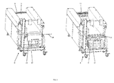
- FIG. 1a shows a food processing unit, here a marination device, particularly an injector 1.
- An injector is a device for introducing a liquid, such as brine, into a food product 2, such as meat, ham and the like, comprising a conveyor belt 3, which is connected at its front ends so that an endless belt is provided and on which the product 2 can be arranged, a needle head 4 at some distance from the conveyor belt 3, the needle head 4 bearing a multiplicity of hollow needles 5 oriented transversely with respect to the conveyor belt 3 and which needle head 4 and its needles 5 will move to and fro the belt for inserting the needles 5 into the food product 2 and therewith supplying a liquid into the food product 2.
- the food product 2 positioned on conveyor belt 3, which is driven by a motor 10, are moving during production from infeed side 19 to outfeed side 20 in production direction shown by arrow 17. However, the food product preferably stands still during the contact with the needles.
- the conveyor belt is removed from the machine 1 and stored in a belt-transportation-trolley 8, as can be seen from figures 1b and 1 c.
- This belt-transportation-trolley 8 comprises a receptacle 14 and and/or is provided with means 7 to coil up the conveyor belt, here a hoisting device 7, which is placed above the receptacle 14.
- the actual removal or repositioning of the conveyor belt 3 is preferably supported by a belt drive motor 10 which is used to rotate the endless belt 3 during production and can be activated with, for example, a jog-function push button.
- Other drive means or other ways to move the belt in the direction of belt-transportation-trolley 8, for example manually, is also possible.
- the conveyor belt 3 here an endless plastic belt 3, rotates around a drive shaft 11 and an idle shaft 12.
- the drive shaft 11, which is driven by a motor, comprises here sprockets at its circumference.
- the idle shaft 12 is preferably also provided with sprockets.
- the sprockets of the drive shaft will hook into form-fit-means in and/or at, preferably the backside of, the conveyor belt.
- the described invention in this patent application is not limited to this drive means and/or this conveyor belt design.
- belts and drive means can be, for example, pre-shaped shafts which are in direct contact with the conveyor belt, wire belt, steel belt, and belt driven by friction, etc.
- a belt guide module 9 can be used to remove the conveyor belt from the food processing unit. This module 9 is preferably placed at the drive shaft side and around the drive shaft 11 to secure a form-, force- and/or friction-connection between the conveyor belt and belt drive, in the present case, the sprockets on the drive shaft. Other means to secure this connection are also feasible.
- the belt-transportation-trolley 8 will be placed here at the idle shaft side.
- connection means 18 between two opposite ends of the conveyor belt 3 the front end of the lower part 13 of this conveyor belt can be led towards the receptacle 14 of the belt-transportation-trolley 8.
- the receptacle is placed below the transportation plane of the conveyor belt 3.
- the conveyor belt 3 runs driven by the drive shaft 11 into the receptacle 14 of the belt-transportation-trolley 8.
- the last part of the conveyor belt slides via gravity in this receptacle.
- the conveyor belt is folded in the receptacle.
- the conveyor belt runs driven by the drive shaft into the receptacle 14 of the belt-transportation-trolley 8.
- the conveyor belt is folded in the receptacle.
- Figure 4 depicts a third preferred embodiment of the present invention.
- the upper part 15 of this belt can be connected for example with the connection means 18 to the coil up means 7 the belt transportation trolley, here a hoisting device 7 which comprises a hoisting device shaft 16.
- This shaft is placed above the transportation plane of the conveyor belt.
- This shaft can be driven by electric drive means but preferably a manual drive will be used as shown in this Figure.
- the conveyor belt can be lowered into the receptacle 14. During this movement of the conveyor belt, preferably the cleaning takes place.
- the conveyor belt is folded in the receptacle.
- a forth preferred embodiment which is not depicted, is similar to the embodiment shown in Figure 4 .
- the lower part 13 of the conveyor belt 3 is connected to the coil up means 7 and then the conveyor belt is coiled up.
- FIG. 5 Each of the above mentioned belt removing procedures results in a machine which is well accessible for cleaning.
- the conveyor belt is either rolled up or placed into the receptacle 14.
- the means 7, 16 can be used for lowering and/or lifting the conveyor belt. Because of the mobility of the belt transportation trolley, cleaning can be done remote from the food processing unit.
- the conveyor belt 3 can be lifted from receptacle 14 to the higher positioned hoisting device shaft 16 and vice versa, which enables an optimization of a step-by-step, front and back cleaning procedure of the entire conveyor belt.
- the conveyor belt itself has a production and a non production side. After cleaning the belt, it has to be repositioned in the machine with its right side up. Removing the conveyor belt, the way as described according to Fig. 3 results in a position of the belt with its wrong side up for repositioning into the machine. To avoid this mishap, the receptacle 14 including the belt 3 can be turned 180° around a vertical axis which enables a correct reposition of the belt.
- the belt-transportation-trolley with an entirely coiled up conveyor belt on the hoisting device shaft 16 will be positioned at the idle shaft 12 side of the food processing unit.
- belt guide module 9 will be used to secure a connection between the belt and the belt drive, in this embodiment the sprockets on drive shaft 11. Other means to secure this connection are possible too.
- the belt can be uncoiled/rolled off from the belt-transportation-trolley by using the hoisting device 7 and by pushing the belt manually towards the eventually used guide module and the belt drive.
- the belt is sufficiently connected with the belt drive, in this embodiment the sprockets on drive shaft 11, the jog-function of the drive motor pulls the entire belt back into its original position.
- both ends of the belt can be connected to each other with connection means 18, creating an endless conveyor belt ready for production.
- the belt can also be handled / positioned manually on the machine without use of any drive means.
- the drive shaft which is directly connected with the drive motor, has to be provided with a freewheel arrangement in order to rotate the drive shaft manually.
- Other ways to move the belt and/or position the belt in the machine are also possible.
- conveyor belt 3 will be removed from / placed on the machine at the side were the idle shaft 12 is positioned, which is at the infeed side 19 of the food processing unit.
- the idle shaft 12 and thus the position were the conveyor belt will be removed / placed, will be the outfeed side 20 of the food processing unit and the drive shaft 11 will then be positioned at the infeed side 19 of the food processing unit.
- the belt transportation trolley can also be positioned next to the end of the processing unit where the drive shaft 11 is located and the conveyor belt will be assembled and disassembled from this end.
- This invention is described by means of an injector but is not limited thereto and can also be used in combination with another food processing unit and/or another processing unit in general.
Abstract
Description
- The present invention relates to a belt-transportation-trolley and a system comprising a food processing unit and the belt-transportation-trolley. The present invention further relates to a method to remove and reassemble a conveyor belt, particularly from a food processing unit.
- Food processing units, like, for example, marination-devices, formers need to be cleaned in short intervals. In many cases, these units comprise a conveyor belt to transport the food to be treated and/or which has been treated. For the cleaning purposes of the unit itself, but also of the belt, the belt has to be removed.
- It was therefore the objective of the present invention to provide a belt-transportation-unit.
- The problem is solved with a belt-transportation-trolley comprising means to store the conveyor belt.
- The disclosure made regarding this subject matter also applies to the other subject matters and vice versa.
- The inventive belt-transportation-trolley has the advantage that a single person is able to assemble and/or reassemble a belt from a production unit. Preferably, no other processing units in a line of multiple processing units need to be translocated for the assembly/disassembly of the conveyor belt.
- The present invention relates to a belt-transportation-trolley. This belt-transportation-trolley is preferably utilized in production fields with high hygienic standards like for example the food-and/or the pharmaceutical industry. A processing unit according to the present invention is a unit in which a material is altered in its shape and/or consistency. Preferably the processing unit is a food processing unit, which for example, cuts, forms, cooks, fries, marinates, massages, cools, freezes, portions of a food product, particularly a protein containing food product.
- The conveyor belt is preferably made from a plastic and/or metal-material, wherein the surface, which is in contact with the product, preferably the food product is preferably smooth. On its backside the conveyor belt preferably comprises form- and/or force-fit-means, which cooperate with corresponding form- and/or force-fit means of a drive mechanism.
- The belt-transportation-trolley can be accommodated next to a processing unit, for example a food-processing-unit, to take over a conveyor belt which has been removed from the processing unit. The belt-transportation trolley comprises means to store the conveyor belt.
- This means can be a receptacle, into which the conveyor belt is placed. Preferably, this receptacle is designed and/or arranged such, that no debris and/or liquid can accumulate in the receptacle and/or that the conveyor belt is folded. More preferably, the receptacle is designed as a bar-construction. Preferably, the receptacle itself is essentially U-shaped, more preferably designed from bars, preferably with a circular cross-section. The front- and the back end of the U are preferably open. Preferably, the receptacle is rotatable around a vertical axis, more preferably by 180°. The receptacle is preferably placed in or below the plane on which the conveyor belt transports food products in a food processing unit.
- Alternatively or additionally, the inventive belt-transportation-trolley comprises means to coil up the conveyor belt. This means is for example a hoisting device or an axel around which the conveyor belt is rolled and which turns around a horizontal axis. The means are preferably driven manually, but can be motorized as well. Preferably, the means can be turned in two directions. The axel of the means to coil up the conveyor belt is preferably placed in or above the plane on which the conveyor belt transports food products in a food processing unit.
- Preferably, the means to coil up the conveyor belt is placed above the receptacle. More preferably, the distance between means to coil up and the receptacle is sufficient to clean the conveyor belt, preferably on two opposite sides.
- The means to coil up the conveyor belt can be utilized to lower and/or lift the conveyor belt out of the receptacle or into the receptacle.
- The belt-transportation-trolley preferably comprises means to move it easily, like one or more wheels. This preferred embodiment of the present invention allows to clean the conveyor belt remote from the food processing unit.
- Another subject matter of the present invention is a system comprising a food processing unit with a conveyor belt and the inventive belt-transportation-trolley.
- The disclosure made regarding this subject matter also applies to the other subject matters and vice versa.
- The belt-transportation-trolley is placed next to the processing unit, preferably the food processing unit whenever the belt needs to be removed from the processing unit. The conveyor belt can be stored in/on the means of the belt-transportation-trolley and/or can be transported to a remote location where it is stored and/or cleaned. Furthermore the belt-transportation-trolley can be utilized to transport the conveyor belt back to the processing unit. After the conveyor belt has been placed into the receptacle, the conveyor belt can coiled up by the corresponding means of the trolley and/or the receptacle can be turned around a vertical axis by preferably 180°. Alternatively, the conveyor belt is coiled up and then lowered into the receptacle. During roll-up and/or roll-off, the belt is preferably cleaned, preferably cleaned on two opposite sides.
- Preferably, the processing unit comprises an infeed- and an outfeed-side. The trolley can be placed at the infeed or at the outfeed side.
- Preferably, the processing unit comprises belt drive means, preferably a motor, that more preferably drives form- and/or force-fit-means, for example a sprocket or the like.
- Even more preferably, the processing unit comprises a conveyor belt guide module, which guides the belt and/or assures the contact between the conveyor belt and the drive means. The drive and/or the guide module can be utilized to assemble or disassemble the conveyor belt.
- Another subject matter of the present invention is a method to remove and reassembly a conveyor belt at a processing unit, preferably a food processing unit with the inventive belt-transportation-trolley, wherein:
- a first and a second end of the conveyor belt are disconnected,
- the conveyor belt is moved into a receptacle or coiled up on means of the belt-transportation-trolley,
- the conveyor belt is removed from the receptacle or the coiling means and reassembled at the food processing unit and
- the first and the second end of the conveyor belt are connected again.
- The disclosure made regarding this subject matter also applies to the other subject matters and vice versa.
- This subject matter of the present invention relates to a method to remove a conveyor belt from a food processing unit, so that, for example, the food processing unit and/or the conveyor belt can be cleaned. Subsequently, the conveyor belt is reassembled at the food processing unit.
- In a first step, two ends of the conveyor belt are disconnected and then the conveyor belt is moved manually, by motor means and/or by gravity in or into the receptacle or coiled up by corresponding coiling means. For reassembly or prior to reassembly, the conveyor belt is removed from the receptacle or rolled off and reassembled at the food processing unit.
- Preferably, the conveyor belt is lifted out of the receptacle prior to its reassembly at the food processing unit. This lifting is preferably carried out by coiling the conveyor belt around a means which is located above the receptacle.
- Preferably, the belt is turned around a vertical axis by 180° prior to its reassembly at the food processing unit.
- Alternatively the conveyor belt is lowered into the receptacle by roll off means prior to its reassembly at the food processing unit.
- Preferably, the conveyor belt is cleaned during lifting and/or lowering. The cleaning can be carried out with nozzles, brushes, a cloth or the like. Preferably a cleaning agent like water or a water based liquid are used. However other cleaning agents are also feasible. Preferably, the conveyor belt is dried after its cleaning. The conveyor belt can be disinfected prior to its reassembly.
- Due the present inventions, both machine and front and back of belt can be cleaned thoroughly. The system enables repositioning of the belt into the machine under same conditions as the removal conditions.
- The inventions are now explained according to
Figures 1 - 7 . These explanations do not limit the scope of protection of the present invention and apply to all inventions of the present application likewise. - Fig. 1a
- shows a food processing unit, here a marination device.
- Fig. 1b
- shows a system comprising the food processing device and the belt-transportation-trolley.
- Fig. 1c
- shows the conveyor belt of the food processing unit.
- Fig. 2
- shows a first embodiment of the removal of the conveyor belt.
- Fig. 3
- shows a second embodiment of the removal of the conveyor belt.
- Fig. 4
- shows a third embodiment of the removal of the conveyor belt.
- Fig. 5
- shows the coiling of the conveyor belt.
- Fig. 6
- shows the preparation of the reassembly of the conveyor belt.
- Fig. 7
- shows one embodiment of the positioning/reassembling of the conveyor belt in the food processing unit.
- All examples refer to a food processing unit. However, the present invention is not restricted to food processing units, but can be utilized in combination with each processing unit, particularly production units which must meet a high hygienic standard.
-
Figure 1a ) shows a food processing unit, here a marination device, particularly aninjector 1. An injector is a device for introducing a liquid, such as brine, into afood product 2, such as meat, ham and the like, comprising aconveyor belt 3, which is connected at its front ends so that an endless belt is provided and on which theproduct 2 can be arranged, aneedle head 4 at some distance from theconveyor belt 3, theneedle head 4 bearing a multiplicity ofhollow needles 5 oriented transversely with respect to theconveyor belt 3 and which needlehead 4 and itsneedles 5 will move to and fro the belt for inserting theneedles 5 into thefood product 2 and therewith supplying a liquid into thefood product 2. Thefood product 2 positioned onconveyor belt 3, which is driven by amotor 10, are moving during production frominfeed side 19 tooutfeed side 20 in production direction shown byarrow 17. However, the food product preferably stands still during the contact with the needles. - For hygienic reasons the
food processing unit 1 has to be cleaned frequently. To enable complete cleaning, accessibility and inspection of the machine andconveyor belt 3, the conveyor belt is removed from themachine 1 and stored in a belt-transportation-trolley 8, as can be seen fromfigures 1b and 1 c. This belt-transportation-trolley 8 comprises areceptacle 14 and and/or is provided withmeans 7 to coil up the conveyor belt, here ahoisting device 7, which is placed above thereceptacle 14. The actual removal or repositioning of theconveyor belt 3 is preferably supported by abelt drive motor 10 which is used to rotate theendless belt 3 during production and can be activated with, for example, a jog-function push button. Other drive means or other ways to move the belt in the direction of belt-transportation-trolley 8, for example manually, is also possible. - Reference is now made to
Figures 1c and2 . During production on thefood processing unit 1, theconveyor belt 3, here an endlessplastic belt 3, rotates around adrive shaft 11 and anidle shaft 12. Thedrive shaft 11, which is driven by a motor, comprises here sprockets at its circumference. Theidle shaft 12 is preferably also provided with sprockets. To drive the conveyor belt, the sprockets of the drive shaft will hook into form-fit-means in and/or at, preferably the backside of, the conveyor belt. The described invention in this patent application is not limited to this drive means and/or this conveyor belt design. Other combinations of belts and drive means can be, for example, pre-shaped shafts which are in direct contact with the conveyor belt, wire belt, steel belt, and belt driven by friction, etc. Abelt guide module 9 can be used to remove the conveyor belt from the food processing unit. Thismodule 9 is preferably placed at the drive shaft side and around thedrive shaft 11 to secure a form-, force- and/or friction-connection between the conveyor belt and belt drive, in the present case, the sprockets on the drive shaft. Other means to secure this connection are also feasible. - As shown in
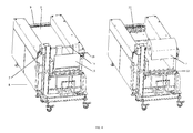
figure 2 the belt-transportation-trolley 8 will be placed here at the idle shaft side. By removing connection means 18 between two opposite ends of theconveyor belt 3, the front end of thelower part 13 of this conveyor belt can be led towards thereceptacle 14 of the belt-transportation-trolley 8. The receptacle is placed below the transportation plane of theconveyor belt 3. By preferably activating the jog-function of the drive motor in a forward direction, opposite toarrow 17, theconveyor belt 3 runs driven by thedrive shaft 11 into thereceptacle 14 of the belt-transportation-trolley 8. Mainly depending on the position of the drive shaft, the design of the machine and/or the weight of the belt, the last part of the conveyor belt slides via gravity in this receptacle. Preferably, the conveyor belt is folded in the receptacle. - Referring now to
figure 3 , a second preferred embodiment of the present invention is depicted. After removing the connection means 18 ofconveyor belt 3, theupper part 15 of this conveyor belt can be led towards thereceptacle 14 of the belt-transportation-trolley 8. By preferably activating the jog-function of the drive motor, in a backwards direction, the conveyor belt runs driven by the drive shaft into thereceptacle 14 of the belt-transportation-trolley 8. Mainly depending on the position of the drive shaft, the design of the machine and the weight of the belt, the last part of the belt slides via gravity in this receptacle. Preferably, the conveyor belt is folded in the receptacle. -
Figure 4 depicts a third preferred embodiment of the present invention. After removing the connection means 18 ofconveyor belt 3, theupper part 15 of this belt can be connected for example with the connection means 18 to the coil upmeans 7 the belt transportation trolley, here ahoisting device 7 which comprises ahoisting device shaft 16. This shaft is placed above the transportation plane of the conveyor belt. This shaft can be driven by electric drive means but preferably a manual drive will be used as shown in this Figure. By activating the jog-function of the drive motor and/or activating themeans 16, the entire belt can be coiled up onto, for example, the hoistingdevice shaft 16 of the belt-transportation-trolley 8. For cleaning purposes, the conveyor belt can be lowered into thereceptacle 14. During this movement of the conveyor belt, preferably the cleaning takes place. Preferably, the conveyor belt is folded in the receptacle. - A forth preferred embodiment, which is not depicted, is similar to the embodiment shown in
Figure 4 . However, thelower part 13 of theconveyor belt 3 is connected to the coil up means 7 and then the conveyor belt is coiled up. - Reference is now made to
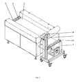
Figure 5 . Each of the above mentioned belt removing procedures results in a machine which is well accessible for cleaning. The conveyor belt is either rolled up or placed into thereceptacle 14. Themeans - As shown in
Figure 6 , by means of thehoisting device 7, theconveyor belt 3 can be lifted fromreceptacle 14 to the higher positioned hoistingdevice shaft 16 and vice versa, which enables an optimization of a step-by-step, front and back cleaning procedure of the entire conveyor belt. The conveyor belt itself has a production and a non production side. After cleaning the belt, it has to be repositioned in the machine with its right side up. Removing the conveyor belt, the way as described according toFig. 3 results in a position of the belt with its wrong side up for repositioning into the machine. To avoid this mishap, thereceptacle 14 including thebelt 3 can be turned 180° around a vertical axis which enables a correct reposition of the belt. - As shown in
Figure 7 , for repositioning of theconveyor belt 3 back into the machine, the belt-transportation-trolley with an entirely coiled up conveyor belt on thehoisting device shaft 16 will be positioned at theidle shaft 12 side of the food processing unit. Preferablybelt guide module 9 will be used to secure a connection between the belt and the belt drive, in this embodiment the sprockets ondrive shaft 11. Other means to secure this connection are possible too. - The belt can be uncoiled/rolled off from the belt-transportation-trolley by using the
hoisting device 7 and by pushing the belt manually towards the eventually used guide module and the belt drive. When the belt is sufficiently connected with the belt drive, in this embodiment the sprockets ondrive shaft 11, the jog-function of the drive motor pulls the entire belt back into its original position. After theentire conveyor belt 3 is removed from the cleaning device, both ends of the belt can be connected to each other with connection means 18, creating an endless conveyor belt ready for production. - Besides the procedure described above, the belt can also be handled / positioned manually on the machine without use of any drive means. For this, the drive shaft, which is directly connected with the drive motor, has to be provided with a freewheel arrangement in order to rotate the drive shaft manually.
Other ways to move the belt and/or position the belt in the machine are also possible. In above described embodiments,conveyor belt 3 will be removed from / placed on the machine at the side were theidle shaft 12 is positioned, which is at theinfeed side 19 of the food processing unit. In another, not shown embodiment, theidle shaft 12, and thus the position were the conveyor belt will be removed / placed, will be theoutfeed side 20 of the food processing unit and thedrive shaft 11 will then be positioned at theinfeed side 19 of the food processing unit. - In all described embodiments, the belt transportation trolley can also be positioned next to the end of the processing unit where the
drive shaft 11 is located and the conveyor belt will be assembled and disassembled from this end. - This invention is described by means of an injector but is not limited thereto and can also be used in combination with another food processing unit and/or another processing unit in general.
-
- 1
- injector / machine, processing unit, food processing unit
- 2
- product, food product
- 3
- conveyor belt
- 4
- needle head
- 5
- needles
- 6
- system
- 7
- means to store the conveyor belt, means to coil up the conveyor belt, hoisting device
- 8
- Belt-transportation-trolley
- 9
- belt guide module
- 10
- belt drive motor
- 11
- drive shaft
- 12
- idle shaft
- 13
- lower end of
conveyor belt 3 - 14
- means to store the conveyor belt, receptacle
- 15
- upper end of
conveyor belt 3 - 16
- axel, hoisting device
- 17
- arrow showing production direction
- 18
- connection means
- 19
- infeed side
- 20
- outfeed side
Claims (15)
- Belt-transportation-trolley (8) comprising means (7, 14) to store the conveyor belt (3).
- Belt-transportation-trolley (8) according to claim 1, characterized in, that the means (7, 14) is a means to coil up the conveyor belt and/or a receptacle (14) for a conveyor belt, into which the conveyor belt is preferably folded.
- Belt-transportation-trolley (8) according to claim 1 or 2, characterized in, that the means (7) to coil up the conveyor belt is placed above the receptacle (14).
- Belt-transportation-trolley (8) according to one of the preceding claims, characterized in, that the distance between means (7) and means (14) is sufficient to clean the conveyor belt, preferably on two opposite sides.
- Belt-transportation-trolley (8) according to claims 1 - 4, characterized in, that the receptacle is rotatable around a vertical axis.
- Belt-transportation-trolley (8) according to one the preceding claims, characterized in, that the means (7) is a hoisting device or an axel.
- System (6) comprising a food processing unit (1) with a conveyor belt (3) and a trolley according to one of the preceding claims.
- Method to remove and reassemble a conveyor belt (3) at a food processing unit (1) with a belt-transportation-trolley according to one of the preceding claims, wherein:- a first and a second end of the conveyor belt are disconnected,- the conveyor belt is moved into a receptacle (14) or coiled up on means (16) of the belt-transportation-trolley,- the conveyor belt is removed from the receptacle (14) or the means (16) and reassembled at the food processing unit and- the first- and the second end of the conveyor belt will be connected again.
- Method according to claim 8, characterized in, that during removal the conveyor belt (3) is placed into the receptacle (14) and for reassembly, preferably rolled off from the means (7) and vice versa.
- Method according to claim 8 or 9, characterized in, that the conveyor belt is lifted out of the receptacle by the means (7) prior to its reassembly at the food processing unit (1).
- Method according to claim 8, characterized in, that, during removal, the conveyor belt (3) will be positioned on the means (7) and for reassembly preferably rolled off from the means (7).
- Method according to claim 8 or 9 or 11, characterized in, that the conveyor belt is lowered into the receptacle by the means (7) prior to its reassembly at the food processing unit (1).
- Method according to claim 10 or 12, characterized in, that the conveyor belt is coiled up during its lifting and rolled off during lowering.
- Method according to claims 8 or 13, characterized in, that the conveyor belt is turned around a vertical axis by 180° prior to its reassembly.
- Method according to claims 8 - 14, characterized in, that the conveyor belt is cleaned during the transfer from means (7) to means (14) and vice versa and is preferably dried after its cleaning.
Priority Applications (2)
| Application Number | Priority Date | Filing Date | Title |
|---|---|---|---|
| PL14178179T PL2845826T3 (en) | 2013-07-30 | 2014-07-23 | Belt-transportation-trolley |
| EP14178179.9A EP2845826B1 (en) | 2013-07-30 | 2014-07-23 | Belt-transportation-trolley |
Applications Claiming Priority (2)
| Application Number | Priority Date | Filing Date | Title |
|---|---|---|---|
| EP13178495 | 2013-07-30 | ||
| EP14178179.9A EP2845826B1 (en) | 2013-07-30 | 2014-07-23 | Belt-transportation-trolley |
Publications (3)
| Publication Number | Publication Date |
|---|---|
| EP2845826A2 true EP2845826A2 (en) | 2015-03-11 |
| EP2845826A3 EP2845826A3 (en) | 2015-06-03 |
| EP2845826B1 EP2845826B1 (en) | 2019-03-13 |
Family
ID=48877122
Family Applications (1)
| Application Number | Title | Priority Date | Filing Date |
|---|---|---|---|
| EP14178179.9A Active EP2845826B1 (en) | 2013-07-30 | 2014-07-23 | Belt-transportation-trolley |
Country Status (4)
| Country | Link |
|---|---|
| EP (1) | EP2845826B1 (en) |
| DK (1) | DK2845826T3 (en) |
| ES (1) | ES2728200T3 (en) |
| PL (1) | PL2845826T3 (en) |
Cited By (2)
| Publication number | Priority date | Publication date | Assignee | Title |
|---|---|---|---|---|
| CN111994153A (en) * | 2020-08-27 | 2020-11-27 | 易宗宏 | Desert cuttage branch sand prevention handcart |
| CN112278053A (en) * | 2020-10-29 | 2021-01-29 | 安徽纳赫智能科技有限公司 | Storage equipment of metal stamping plate |
Family Cites Families (5)
| Publication number | Priority date | Publication date | Assignee | Title |
|---|---|---|---|---|
| IT1135808B (en) * | 1981-05-15 | 1986-08-27 | Achille Gerosa | TROLLEY FOR AUTOMATIC LOADING OF FRAMES WITH BREAD SHAPES, PARTICULARLY COMBINED WITH PRINTING MACHINES FOR SUCH SHAPES |
| US4754885A (en) * | 1986-05-16 | 1988-07-05 | Rich Beverly C | Knockdown mobile forms cart |
| DE3837149C2 (en) * | 1988-11-02 | 1998-06-04 | Phoenix Ag | Double winding for the assembly of conveyor belts |
| FR2663309B1 (en) * | 1990-06-15 | 1994-06-17 | Rozier Jean Michel | CONVEYOR WITH CONVEYOR BELT WITH RAPID DISASSEMBLY AND REASSEMBLY OF THE BELT. |
| US5706932A (en) * | 1996-03-27 | 1998-01-13 | White; Robert G. | Apparatus and method of cleaning conveyor belts |
-
2014
- 2014-07-23 PL PL14178179T patent/PL2845826T3/en unknown
- 2014-07-23 ES ES14178179T patent/ES2728200T3/en active Active
- 2014-07-23 EP EP14178179.9A patent/EP2845826B1/en active Active
- 2014-07-23 DK DK14178179.9T patent/DK2845826T3/en active
Non-Patent Citations (1)
| Title |
|---|
| None |
Cited By (3)
| Publication number | Priority date | Publication date | Assignee | Title |
|---|---|---|---|---|
| CN111994153A (en) * | 2020-08-27 | 2020-11-27 | 易宗宏 | Desert cuttage branch sand prevention handcart |
| CN111994153B (en) * | 2020-08-27 | 2022-07-26 | 浙江普莱德休闲用品有限公司 | Desert cutting sand prevention trolley |
| CN112278053A (en) * | 2020-10-29 | 2021-01-29 | 安徽纳赫智能科技有限公司 | Storage equipment of metal stamping plate |
Also Published As
| Publication number | Publication date |
|---|---|
| EP2845826A3 (en) | 2015-06-03 |
| ES2728200T3 (en) | 2019-10-22 |
| EP2845826B1 (en) | 2019-03-13 |
| PL2845826T3 (en) | 2019-08-30 |
| DK2845826T3 (en) | 2019-05-27 |
Similar Documents
| Publication | Publication Date | Title |
|---|---|---|
| CN104723395B (en) | Semen Arecae belt conveying cuts seed machine | |
| EP1205111A1 (en) | Apparatus for transferring poultry carcasses | |
| EP2845826B1 (en) | Belt-transportation-trolley | |
| JP2009501118A (en) | Conveyor device provided with a shaft rotating hook | |
| CN105129317A (en) | Asparagus root cutting and packing equipment | |
| CN102160557A (en) | Food processing tray dumping stripper | |
| KR100763576B1 (en) | Automatic supply and transfer apparatus of roast bar | |
| CN112547556A (en) | Loquat leaf processing apparatus that can filter yellow leaf of plant diseases and insect pests | |
| US7934442B2 (en) | Apparatus for removing a stockinette | |
| KR101318996B1 (en) | Pinbone removal device of tongs type fish flake | |
| JP2012101885A (en) | Carrying conveyor | |
| JP4659535B2 (en) | Roller conveyor | |
| CN107583064A (en) | A kind of automobile-used high temperature sterilizer of supermarket shopping | |
| RU2005131387A (en) | DEVICE FOR MOVING PRODUCTS | |
| JP3162985U (en) | Animal thigh meat removal device from crotch | |
| CN209701625U (en) | A kind of carrier return wire | |
| JP2009045029A (en) | Chamber device | |
| JP2007185122A (en) | Transporting apparatus | |
| JP3041626U (en) | Food cutting equipment | |
| CN202147991U (en) | Self-tensioning conveying and lifting device | |
| CN213246798U (en) | Kick-out device and gas bath cleaning machine | |
| CN213893165U (en) | Sealing machine with dust collector | |
| CN210709563U (en) | Food raw material production line material conveying equipment | |
| CN210794847U (en) | Switching conveying mechanism | |
| JP6004713B2 (en) | Skewers |
Legal Events
| Date | Code | Title | Description |
|---|---|---|---|
| 17P | Request for examination filed |
Effective date: 20140723 |
|
| AK | Designated contracting states |
Kind code of ref document: A2 Designated state(s): AL AT BE BG CH CY CZ DE DK EE ES FI FR GB GR HR HU IE IS IT LI LT LU LV MC MK MT NL NO PL PT RO RS SE SI SK SM TR |
|
| AX | Request for extension of the european patent |
Extension state: BA ME |
|
| PUAI | Public reference made under article 153(3) epc to a published international application that has entered the european phase |
Free format text: ORIGINAL CODE: 0009012 |
|
| PUAL | Search report despatched |
Free format text: ORIGINAL CODE: 0009013 |
|
| AK | Designated contracting states |
Kind code of ref document: A3 Designated state(s): AL AT BE BG CH CY CZ DE DK EE ES FI FR GB GR HR HU IE IS IT LI LT LU LV MC MK MT NL NO PL PT RO RS SE SI SK SM TR |
|
| AX | Request for extension of the european patent |
Extension state: BA ME |
|
| RIC1 | Information provided on ipc code assigned before grant |
Ipc: B65H 18/28 20060101AFI20150424BHEP Ipc: B65H 16/00 20060101ALI20150424BHEP Ipc: B65H 75/02 20060101ALI20150424BHEP Ipc: B65H 18/08 20060101ALI20150424BHEP |
|
| R17P | Request for examination filed (corrected) |
Effective date: 20151202 |
|
| RBV | Designated contracting states (corrected) |
Designated state(s): AL AT BE BG CH CY CZ DE DK EE ES FI FR GB GR HR HU IE IS IT LI LT LU LV MC MK MT NL NO PL PT RO RS SE SI SK SM TR |
|
| REG | Reference to a national code |
Ref country code: DE Ref legal event code: R079 Ref document number: 602014042694 Country of ref document: DE Free format text: PREVIOUS MAIN CLASS: B65H0018280000 Ipc: B65H0016000000 |
|
| RIC1 | Information provided on ipc code assigned before grant |
Ipc: B65H 75/00 20060101ALI20180712BHEP Ipc: B65H 18/08 20060101ALI20180712BHEP Ipc: B65H 16/00 20060101AFI20180712BHEP Ipc: B62B 3/00 20060101ALI20180712BHEP Ipc: B65H 75/02 20060101ALI20180712BHEP |
|
| GRAP | Despatch of communication of intention to grant a patent |
Free format text: ORIGINAL CODE: EPIDOSNIGR1 |
|
| STAA | Information on the status of an ep patent application or granted ep patent |
Free format text: STATUS: GRANT OF PATENT IS INTENDED |
|
| INTG | Intention to grant announced |
Effective date: 20180928 |
|
| GRAS | Grant fee paid |
Free format text: ORIGINAL CODE: EPIDOSNIGR3 |
|
| GRAA | (expected) grant |
Free format text: ORIGINAL CODE: 0009210 |
|
| STAA | Information on the status of an ep patent application or granted ep patent |
Free format text: STATUS: THE PATENT HAS BEEN GRANTED |
|
| AK | Designated contracting states |
Kind code of ref document: B1 Designated state(s): AL AT BE BG CH CY CZ DE DK EE ES FI FR GB GR HR HU IE IS IT LI LT LU LV MC MK MT NL NO PL PT RO RS SE SI SK SM TR |
|
| REG | Reference to a national code |
Ref country code: GB Ref legal event code: FG4D |
|
| REG | Reference to a national code |
Ref country code: AT Ref legal event code: REF Ref document number: 1107411 Country of ref document: AT Kind code of ref document: T Effective date: 20190315 Ref country code: CH Ref legal event code: EP |
|
| REG | Reference to a national code |
Ref country code: IE Ref legal event code: FG4D |
|
| REG | Reference to a national code |
Ref country code: DE Ref legal event code: R096 Ref document number: 602014042694 Country of ref document: DE |
|
| REG | Reference to a national code |
Ref country code: DK Ref legal event code: T3 Effective date: 20190522 |
|
| REG | Reference to a national code |
Ref country code: NL Ref legal event code: FP |
|
| REG | Reference to a national code |
Ref country code: SE Ref legal event code: TRGR |
|
| REG | Reference to a national code |
Ref country code: LT Ref legal event code: MG4D |
|
| PG25 | Lapsed in a contracting state [announced via postgrant information from national office to epo] |
Ref country code: LT Free format text: LAPSE BECAUSE OF FAILURE TO SUBMIT A TRANSLATION OF THE DESCRIPTION OR TO PAY THE FEE WITHIN THE PRESCRIBED TIME-LIMIT Effective date: 20190313 |
|
| PG25 | Lapsed in a contracting state [announced via postgrant information from national office to epo] |
Ref country code: RS Free format text: LAPSE BECAUSE OF FAILURE TO SUBMIT A TRANSLATION OF THE DESCRIPTION OR TO PAY THE FEE WITHIN THE PRESCRIBED TIME-LIMIT Effective date: 20190313 Ref country code: LV Free format text: LAPSE BECAUSE OF FAILURE TO SUBMIT A TRANSLATION OF THE DESCRIPTION OR TO PAY THE FEE WITHIN THE PRESCRIBED TIME-LIMIT Effective date: 20190313 Ref country code: HR Free format text: LAPSE BECAUSE OF FAILURE TO SUBMIT A TRANSLATION OF THE DESCRIPTION OR TO PAY THE FEE WITHIN THE PRESCRIBED TIME-LIMIT Effective date: 20190313 Ref country code: GR Free format text: LAPSE BECAUSE OF FAILURE TO SUBMIT A TRANSLATION OF THE DESCRIPTION OR TO PAY THE FEE WITHIN THE PRESCRIBED TIME-LIMIT Effective date: 20190614 Ref country code: BG Free format text: LAPSE BECAUSE OF FAILURE TO SUBMIT A TRANSLATION OF THE DESCRIPTION OR TO PAY THE FEE WITHIN THE PRESCRIBED TIME-LIMIT Effective date: 20190613 |
|
| REG | Reference to a national code |
Ref country code: NO Ref legal event code: T2 Effective date: 20190313 |
|
| REG | Reference to a national code |
Ref country code: ES Ref legal event code: FG2A Ref document number: 2728200 Country of ref document: ES Kind code of ref document: T3 Effective date: 20191022 |
|
| PG25 | Lapsed in a contracting state [announced via postgrant information from national office to epo] |
Ref country code: PT Free format text: LAPSE BECAUSE OF FAILURE TO SUBMIT A TRANSLATION OF THE DESCRIPTION OR TO PAY THE FEE WITHIN THE PRESCRIBED TIME-LIMIT Effective date: 20190713 Ref country code: AL Free format text: LAPSE BECAUSE OF FAILURE TO SUBMIT A TRANSLATION OF THE DESCRIPTION OR TO PAY THE FEE WITHIN THE PRESCRIBED TIME-LIMIT Effective date: 20190313 Ref country code: EE Free format text: LAPSE BECAUSE OF FAILURE TO SUBMIT A TRANSLATION OF THE DESCRIPTION OR TO PAY THE FEE WITHIN THE PRESCRIBED TIME-LIMIT Effective date: 20190313 Ref country code: CZ Free format text: LAPSE BECAUSE OF FAILURE TO SUBMIT A TRANSLATION OF THE DESCRIPTION OR TO PAY THE FEE WITHIN THE PRESCRIBED TIME-LIMIT Effective date: 20190313 Ref country code: SK Free format text: LAPSE BECAUSE OF FAILURE TO SUBMIT A TRANSLATION OF THE DESCRIPTION OR TO PAY THE FEE WITHIN THE PRESCRIBED TIME-LIMIT Effective date: 20190313 Ref country code: RO Free format text: LAPSE BECAUSE OF FAILURE TO SUBMIT A TRANSLATION OF THE DESCRIPTION OR TO PAY THE FEE WITHIN THE PRESCRIBED TIME-LIMIT Effective date: 20190313 |
|
| PG25 | Lapsed in a contracting state [announced via postgrant information from national office to epo] |
Ref country code: SM Free format text: LAPSE BECAUSE OF FAILURE TO SUBMIT A TRANSLATION OF THE DESCRIPTION OR TO PAY THE FEE WITHIN THE PRESCRIBED TIME-LIMIT Effective date: 20190313 |
|
| PGFP | Annual fee paid to national office [announced via postgrant information from national office to epo] |
Ref country code: BE Payment date: 20190722 Year of fee payment: 6 |
|
| REG | Reference to a national code |
Ref country code: DE Ref legal event code: R097 Ref document number: 602014042694 Country of ref document: DE |
|
| PG25 | Lapsed in a contracting state [announced via postgrant information from national office to epo] |
Ref country code: IS Free format text: LAPSE BECAUSE OF FAILURE TO SUBMIT A TRANSLATION OF THE DESCRIPTION OR TO PAY THE FEE WITHIN THE PRESCRIBED TIME-LIMIT Effective date: 20190713 |
|
| PLBE | No opposition filed within time limit |
Free format text: ORIGINAL CODE: 0009261 |
|
| STAA | Information on the status of an ep patent application or granted ep patent |
Free format text: STATUS: NO OPPOSITION FILED WITHIN TIME LIMIT |
|
| 26N | No opposition filed |
Effective date: 20191216 |
|
| PG25 | Lapsed in a contracting state [announced via postgrant information from national office to epo] |
Ref country code: MC Free format text: LAPSE BECAUSE OF FAILURE TO SUBMIT A TRANSLATION OF THE DESCRIPTION OR TO PAY THE FEE WITHIN THE PRESCRIBED TIME-LIMIT Effective date: 20190313 Ref country code: SI Free format text: LAPSE BECAUSE OF FAILURE TO SUBMIT A TRANSLATION OF THE DESCRIPTION OR TO PAY THE FEE WITHIN THE PRESCRIBED TIME-LIMIT Effective date: 20190313 |
|
| PG25 | Lapsed in a contracting state [announced via postgrant information from national office to epo] |
Ref country code: TR Free format text: LAPSE BECAUSE OF FAILURE TO SUBMIT A TRANSLATION OF THE DESCRIPTION OR TO PAY THE FEE WITHIN THE PRESCRIBED TIME-LIMIT Effective date: 20190313 |
|
| REG | Reference to a national code |
Ref country code: AT Ref legal event code: UEP Ref document number: 1107411 Country of ref document: AT Kind code of ref document: T Effective date: 20190313 |
|
| PG25 | Lapsed in a contracting state [announced via postgrant information from national office to epo] |
Ref country code: LU Free format text: LAPSE BECAUSE OF NON-PAYMENT OF DUE FEES Effective date: 20190723 |
|
| PG25 | Lapsed in a contracting state [announced via postgrant information from national office to epo] |
Ref country code: IE Free format text: LAPSE BECAUSE OF NON-PAYMENT OF DUE FEES Effective date: 20190723 |
|
| REG | Reference to a national code |
Ref country code: BE Ref legal event code: MM Effective date: 20200731 |
|
| PG25 | Lapsed in a contracting state [announced via postgrant information from national office to epo] |
Ref country code: CY Free format text: LAPSE BECAUSE OF FAILURE TO SUBMIT A TRANSLATION OF THE DESCRIPTION OR TO PAY THE FEE WITHIN THE PRESCRIBED TIME-LIMIT Effective date: 20190313 Ref country code: BE Free format text: LAPSE BECAUSE OF NON-PAYMENT OF DUE FEES Effective date: 20200731 |
|
| PG25 | Lapsed in a contracting state [announced via postgrant information from national office to epo] |
Ref country code: MT Free format text: LAPSE BECAUSE OF FAILURE TO SUBMIT A TRANSLATION OF THE DESCRIPTION OR TO PAY THE FEE WITHIN THE PRESCRIBED TIME-LIMIT Effective date: 20190313 Ref country code: HU Free format text: LAPSE BECAUSE OF FAILURE TO SUBMIT A TRANSLATION OF THE DESCRIPTION OR TO PAY THE FEE WITHIN THE PRESCRIBED TIME-LIMIT; INVALID AB INITIO Effective date: 20140723 |
|
| PGFP | Annual fee paid to national office [announced via postgrant information from national office to epo] |
Ref country code: FI Payment date: 20210720 Year of fee payment: 8 |
|
| PGFP | Annual fee paid to national office [announced via postgrant information from national office to epo] |
Ref country code: SE Payment date: 20210721 Year of fee payment: 8 Ref country code: NO Payment date: 20210721 Year of fee payment: 8 |
|
| PG25 | Lapsed in a contracting state [announced via postgrant information from national office to epo] |
Ref country code: MK Free format text: LAPSE BECAUSE OF FAILURE TO SUBMIT A TRANSLATION OF THE DESCRIPTION OR TO PAY THE FEE WITHIN THE PRESCRIBED TIME-LIMIT Effective date: 20190313 |
|
| REG | Reference to a national code |
Ref country code: NO Ref legal event code: MMEP |
|
| REG | Reference to a national code |
Ref country code: SE Ref legal event code: EUG |
|
| PG25 | Lapsed in a contracting state [announced via postgrant information from national office to epo] |
Ref country code: SE Free format text: LAPSE BECAUSE OF NON-PAYMENT OF DUE FEES Effective date: 20220724 Ref country code: NO Free format text: LAPSE BECAUSE OF NON-PAYMENT OF DUE FEES Effective date: 20220731 Ref country code: FI Free format text: LAPSE BECAUSE OF NON-PAYMENT OF DUE FEES Effective date: 20220723 |
|
| P01 | Opt-out of the competence of the unified patent court (upc) registered |
Effective date: 20230519 |
|
| PGFP | Annual fee paid to national office [announced via postgrant information from national office to epo] |
Ref country code: NL Payment date: 20230720 Year of fee payment: 10 |
|
| PGFP | Annual fee paid to national office [announced via postgrant information from national office to epo] |
Ref country code: IT Payment date: 20230731 Year of fee payment: 10 Ref country code: GB Payment date: 20230724 Year of fee payment: 10 Ref country code: ES Payment date: 20230821 Year of fee payment: 10 Ref country code: CH Payment date: 20230801 Year of fee payment: 10 Ref country code: AT Payment date: 20230718 Year of fee payment: 10 |
|
| PGFP | Annual fee paid to national office [announced via postgrant information from national office to epo] |
Ref country code: PL Payment date: 20230710 Year of fee payment: 10 Ref country code: FR Payment date: 20230724 Year of fee payment: 10 Ref country code: DK Payment date: 20230724 Year of fee payment: 10 Ref country code: DE Payment date: 20230720 Year of fee payment: 10 |