EP2845798A1 - Routings for articulated landing gear - Google Patents
Routings for articulated landing gear Download PDFInfo
- Publication number
- EP2845798A1 EP2845798A1 EP14170821.4A EP14170821A EP2845798A1 EP 2845798 A1 EP2845798 A1 EP 2845798A1 EP 14170821 A EP14170821 A EP 14170821A EP 2845798 A1 EP2845798 A1 EP 2845798A1
- Authority
- EP
- European Patent Office
- Prior art keywords
- trailing arm
- structural post
- landing gear
- bulkhead
- lines
- Prior art date
- Legal status (The legal status is an assumption and is not a legal conclusion. Google has not performed a legal analysis and makes no representation as to the accuracy of the status listed.)
- Granted
Links
Images


Classifications
-
- B—PERFORMING OPERATIONS; TRANSPORTING
- B64—AIRCRAFT; AVIATION; COSMONAUTICS
- B64C—AEROPLANES; HELICOPTERS
- B64C25/00—Alighting gear
- B64C25/02—Undercarriages
-
- B—PERFORMING OPERATIONS; TRANSPORTING
- B64—AIRCRAFT; AVIATION; COSMONAUTICS
- B64C—AEROPLANES; HELICOPTERS
- B64C25/00—Alighting gear
- B64C25/001—Devices not provided for in the groups B64C25/02 - B64C25/68
Definitions
- the present disclosure relates to landing gear, and more particularly, to routings for articulated landing gear.
- Landing gear supports an aircraft while on the ground.
- An articulated landing gear may include a hollow interior volume.
- Various electrical lines and/or hydraulic lines may be attached to the exterior of the landing gear.
- the electrical lines and/or hydraulic lines may transmit electrical signals and/or hydraulic pressure between the aircraft and the wheels and brakes of the landing gear.
- the electrical lines and/or hydraulic lines may also be used to detect various positional sensors on the landing gear.
- the electrical lines and/or hydraulic lines may cause noise and turbulence while the aircraft is in motion.
- electrical lines and/or hydraulic lines on the exterior of the landing gear may be susceptible to damage from debris, for example in the event of a tire burst, bird strike, etc.
- an articulated landing gear may comprise a structural post and a trailing arm.
- the trailing arm may be coupled to the structural post at a pivot joint.
- At least one of an electrical line and a hydraulic line may be located within the structural post and the trailing arm.
- the at least one of the electrical line and the hydraulic line may comprise at least one electrical line and at least one hydraulic line.
- the at least one of an electrical line and a hydraulic line may comprise a first rigid portion within the structural post, a flexible portion between the structural post and the trailing arm, and a second rigid portion within the trailing arm.
- the first portion may be metallic, and the second portion may comprise at least one of a polymer and rubber.
- an articulated landing gear may comprise a hollow structural post and a first bulkhead located within the hollow structural post. At least one of an electrical line and a hydraulic line may pass through a first guide hole in the first bulkhead.
- the articulated landing gear may further comprise a hollow trailing arm coupled to the hollow structural post.
- the hollow trailing arm may comprise a second bulkhead located within the hollow trailing arm. The at least one of an electrical line and a hydraulic line may pass through a second guide hole in the second bulkhead.
- a system for routing at least one of an electrical line and a hydraulic line may comprise a structural post, a trailing arm coupled to the structural post at a pivot joint, and a bulkhead located within at least one of the structural post and the trailing arm.
- the bulkhead may secure the at least one of an electrical line and a hydraulic line.
- the at least one of an electrical line and a hydraulic line may comprise a first rigid portion within the structural post, a flexible portion around the pivot joint, and a second rigid portion within the trailing arm.
- Articulated landing gear 100 may comprise structural post 110, trailing arm 120, and shock strut 130.
- Structural post 110 may be coupled to trailing arm 120 via pivot joint 140.
- Shock strut 130 may be coupled to structural post 110 at upper post 150 via strut joint 180, and shock strut 130 may be coupled to trailing arm 120 at arm joint 160.
- structural post 110 and upper post 150 may comprise a single structural component.
- Articulated landing gear 100 may further comprise electrical lines and/or hydraulic lines 170. Electrical lines and/or hydraulic lines 170 may be located at least partially within structural post 110 and trailing arm 120.
- Articulated landing gear 100 supports the weight of an aircraft while on ground. An upward force from one or more wheels in contact with the ground may transfer to articulated landing gear 100 at arm joint 160. The force may cause shock strut 130 to compress, and trailing arm 120 to rotate about pivot joint 140 relative to structural post 110. Additionally, shock strut 130 may pivot relative to structural post 110 at strut joint 180. Electrical lines and/or hydraulic lines 170 may bend at pivot joint 140 as trailing arm 120 rotates.
- structural post 110 and trailing arm 120 may comprise hollow tubing.
- the tubing may comprise steel, however in various embodiments the tubing may comprise any material capable of supporting the weight of an aircraft. Due to the hollow nature of structural post 110 and trailing arm 120, various components, such as electrical lines and/or hydraulic lines 170, may be routed through structural post 110 and trailing arm 120. Routing components through structural post 110 and trailing arm 120 may protect the components from debris, reduce drag, and reduce noise from components outside of structural post 110 and trailing arm 120.
- Electrical lines and/or hydraulic lines 170 may transmit power and/or electrical signals through articulated landing gear 100.
- Electrical lines and/or hydraulic lines 170 may comprise lines that carry electrical signals, such as electrical brake lines, temperature sensor lines, wheel speed transducer lines, proximity sensor lines, etc.
- Electrical lines and/or hydraulic lines 170 may comprise lines that carry hydraulic fluid under pressure, such as hydraulic brake lines, etc.
- electrical lines and/or hydraulic lines 170 may be substantially rigid lines located within structural post 110 and/or trailing arm 120.
- electrical lines and/or hydraulic lines 170 may comprise metal tubing, such as aluminum, steel, or copper. Rigid electrical lines and/or hydraulic lines 170 may provide increased durability and reliability over flexible electrical lines and/or hydraulic lines.
- electrical lines and/or hydraulic lines 170 may be substantially flexible in order to allow movement in response to trailing arm 120 rotating relative to structural post 110.
- electrical lines and/or hydraulic lines 170 may be flexible throughout structural post 110, trailing arm 120, and between structural post 110 and trailing arm 120.
- electrical lines and/or hydraulic lines 170 may be routed on the side of pivot joint 140 where an obtuse angle is formed by structural post 110 and trailing arm 120, on the side of pivot joint 140 where a reflex angle is formed by structural post 110 and trailing arm 120, or both.
- the reflex angle side may allow for a larger bend radius for electrical lines and/or hydraulic lines 170, however, the reflex angle side may also result in a greater length of electrical lines and/or hydraulic lines 170 being exposed outside of the structural post 110 and trailing arm 120, resulting in more noise, threat exposure, and drag than on the obtuse angle side.
- the flexible portions of electrical lines and/or hydraulic lines 170 may be coupled to the rigid portions of electrical lines and/or hydraulic lines 170 via one or more fittings.
- the flexible portions of electrical lines and/or hydraulic lines 170 may be replaced without requiring the rigid portions of electrical lines and/or hydraulic lines 170 to be replaced and/or removed from articulated landing gear 100.
- Electrical lines and/or hydraulic lines 170 may be routed through upper post 150 to interface with an airframe. Articulated landing gear 100 may retract into the airframe body by rotating at upper post 150. By routing electrical lines and/or hydraulic lines 170 internally through upper post 150 to the airframe, the possibility of electrical lines and/or hydraulic lines 170 pinching or bending too severely may be reduced during retraction of articulated landing gear 100.
- Structural post 110 may be at least partially hollow.
- electrical lines and/or hydraulic lines 170 may be unsupported throughout at least one of structural post 110 and trailing arm 120. However, in various embodiments, electrical lines and/or hydraulic lines 170 may be supported by at least one bulkhead 210A, 210B, 210C, 210D, 210E, and 210F.
- bulkheads 210A, 210B, 210C, 210D, 210E, and 210F may support electrical lines and/or hydraulic lines 170 and prevent damage or failure from movement, such as vibrations.
- bulkheads 210A, 210B, 210C, 210D, 210E, and 210F may be substantially cylindrical.
- Bulkheads 210A, 210B, 210C, 210D, 210E, and 210F may be kept in place by friction.
- bulkheads 210A, 210B, 210C, 210D, 210E, and 210F may comprise expandable compression joints.
- bulkheads 210A, 210B, 210C, 210D, 210E, and 210F may comprise a compressible material, such that, in response to being placed within structural post 110 or trailing arm 120, contact between bulkheads 210A, 210B, 210C, 210D, 210E, and 210F and structural post 110 or trailing arm 120 keeps bulkheads 210A, 210B, 210C, 210D, 210E, and 210F in a fixed position. It may be desirable for bulkheads 210A, 210B, 210C, 210D, 210E, and 210F to be comprised of a lightweight material.
- bulkheads 210A, 210B, 210C, 210D, 210E, and 210F may be comprised of a polymer or carbon composite.
- pins or screws may be used to secure bulkheads 210A, 210B, 210C, 210D, 210E, and 210F in place.
- bulkheads 210A, 210B, 210C, 210D, 210E, and 210F may be coupled to fittings integral to electrical lines and/or hydraulic lines 170 in order to keep bulkheads 210A, 210B, 210C, 210D, 210E, and 210F in place.
- articulated landing gear 100 may comprise a brace attach spindle pin 230.
- Brace attach spindle pin 230 may extend through pin hole 212 of bulkhead 210C in order to secure bulkhead 210 in place.
- Brace attach spindle pin 230 may couple a locking side brace actuator to the structure of articulated landing gear 100.
- the side brace actuator may lock in a gear down position to maintain articulated landing gear 100 in a down and locked position, and the side brace actuator may retract articulated landing gear 100 into an airframe.
- Articulated landing gear 100 may further comprise brake pin bulkhead 210E.
- Brake pin bulkhead 210E may comprise brake pin 218 which secures brake pin bulkhead 210E in place.
- Brake pin 218 may prevent a brake from rotating about an axle in response to brake torque being applied.
- brace attach spindle pin 230 and/or brake pin 218 may support one or more bulkheads 210A through 210F.
- Trailing arm 120 may comprise a reinforced exit 220.
- Reinforced exit 220 may be a hole in the wall of trailing arm 120 which allows electrical lines and/or hydraulic lines 170 to pass between an interior of trailing arm 120 and the exterior area around pivot joint 140. Reinforced exit 220 may be environmentally sealed to prevent gas or fluids from entering or leaving trailing arm 120 through reinforced exit 220.
- structural post 110 may also comprise a reinforced exit near bulkhead 210A.
- the flexible portion of electrical lines and/or hydraulic lines 170 may be exposed to the elements between trailing arm 120 and structural post 110.
- articulated landing gear 100 may comprise a deflector 240 around pivot joint 140 which protects the flexible portion of electrical lines and/or hydraulic lines 170 and may reduce noise from turbulence caused by electrical lines and/or hydraulic lines 170.
- structural post 110 comprises two electrical lines 310 and two hydraulic lines 320 in the interior of structural post 110.
- structural post 110 may comprise any number of electrical lines and hydraulic lines. Electrical lines 310 and hydraulic lines 320 pass through guide holes 330 in bulkheads 210A through 210F. Guide holes 330 may prevent movement of electrical lines 310 and hydraulic lines 320 in order to prevent damage.
- at least one bulkhead 210D may comprise an upper surface 340 which is slanted downward towards the center of structural post 110. The slanted upper surface 340 may allow fluids to drain through structural post 110 without accumulating on upper surface 340.
- trailing arm 120 is illustrated coupled to axle 410 according to various embodiments.
- electrical lines and/or hydraulic lines 170 may be rigid within trailing arm 120.
- flexible electrical lines and/or hydraulic lines may be located within axle 410, and the flexible electrical lines and/or hydraulic lines may couple to electrical lines and/or hydraulic lines 170 at bulkhead 210F.
- references to "various embodiments”, “one embodiment”, “an embodiment”, “an example embodiment”, etc. indicate that the embodiment described may include a particular feature, structure, or characteristic, but every embodiment may not necessarily include the particular feature, structure, or characteristic. Moreover, such phrases are not necessarily referring to the same embodiment. Further, when a particular feature, structure, or characteristic is described in connection with an embodiment, it is submitted that it is within the knowledge of one skilled in the art to affect such feature, structure, or characteristic in connection with other embodiments whether or not explicitly described. After reading the description, it will be apparent to one skilled in the relevant art(s) how to implement the disclosure in alternative embodiments.
Landscapes
- Engineering & Computer Science (AREA)
- Mechanical Engineering (AREA)
- Aviation & Aerospace Engineering (AREA)
- General Details Of Gearings (AREA)
- Retarders (AREA)
Abstract
Description
- The present disclosure relates to landing gear, and more particularly, to routings for articulated landing gear.
- Landing gear supports an aircraft while on the ground. An articulated landing gear may include a hollow interior volume. Various electrical lines and/or hydraulic lines may be attached to the exterior of the landing gear. The electrical lines and/or hydraulic lines may transmit electrical signals and/or hydraulic pressure between the aircraft and the wheels and brakes of the landing gear. The electrical lines and/or hydraulic lines may also be used to detect various positional sensors on the landing gear. However, the electrical lines and/or hydraulic lines may cause noise and turbulence while the aircraft is in motion. Additionally, electrical lines and/or hydraulic lines on the exterior of the landing gear may be susceptible to damage from debris, for example in the event of a tire burst, bird strike, etc.
- In various embodiments, an articulated landing gear may comprise a structural post and a trailing arm. The trailing arm may be coupled to the structural post at a pivot joint. At least one of an electrical line and a hydraulic line may be located within the structural post and the trailing arm. The at least one of the electrical line and the hydraulic line may comprise at least one electrical line and at least one hydraulic line. The at least one of an electrical line and a hydraulic line may comprise a first rigid portion within the structural post, a flexible portion between the structural post and the trailing arm, and a second rigid portion within the trailing arm. The first portion may be metallic, and the second portion may comprise at least one of a polymer and rubber.
- In various embodiments, an articulated landing gear may comprise a hollow structural post and a first bulkhead located within the hollow structural post. At least one of an electrical line and a hydraulic line may pass through a first guide hole in the first bulkhead. The articulated landing gear may further comprise a hollow trailing arm coupled to the hollow structural post. The hollow trailing arm may comprise a second bulkhead located within the hollow trailing arm. The at least one of an electrical line and a hydraulic line may pass through a second guide hole in the second bulkhead.
- In various embodiments, a system for routing at least one of an electrical line and a hydraulic line may comprise a structural post, a trailing arm coupled to the structural post at a pivot joint, and a bulkhead located within at least one of the structural post and the trailing arm. The bulkhead may secure the at least one of an electrical line and a hydraulic line. The at least one of an electrical line and a hydraulic line may comprise a first rigid portion within the structural post, a flexible portion around the pivot joint, and a second rigid portion within the trailing arm.
- The subject matter of the present disclosure is particularly pointed out and distinctly claimed in the concluding portion of the specification. A more complete understanding of the present disclosure, however, may best be obtained by referring to the detailed description and claims when considered in connection with the drawing figures, wherein like numerals denote like elements.
-
FIG. 1 illustrates, in accordance with various embodiments, a side view of a portion of an articulated landing gear; -
FIG. 2 illustrates, in accordance with various embodiments, a side view of the internal structure of an articulated landing gear; -
FIG. 3 illustrates, in accordance with various embodiments, a perspective view of the internal structure of a structural post; and -
FIG. 4 illustrates, in accordance with various embodiments, a perspective view of the internal structure of a trailing arm. - The detailed description of exemplary embodiments herein makes reference to the accompanying drawings, which show exemplary embodiments by way of illustration and their best mode. While these exemplary embodiments are described in sufficient detail to enable those skilled in the art to practice the inventions, it should be understood that other embodiments may be realized and that logical, chemical and mechanical changes may be made without departing from the scope of the inventions. Thus, the detailed description herein is presented for purposes of illustration only and not of limitation. For example, the steps recited in any of the method or process descriptions may be executed in any order and are not necessarily limited to the order presented. Furthermore, any reference to singular includes plural embodiments, and any reference to more than one component or step may include a singular embodiment or step. Also, any reference to attached, fixed, connected or the like may include permanent, removable, temporary, partial, full and/or any other possible attachment option. Additionally, any reference to without contact (or similar phrases) may also include reduced contact or minimal contact.
- Referring to
FIG. 1 , a portion of an articulatedlanding gear 100 is illustrated according to various embodiments.Articulated landing gear 100 may comprisestructural post 110,trailing arm 120, andshock strut 130.Structural post 110 may be coupled to trailingarm 120 viapivot joint 140.Shock strut 130 may be coupled tostructural post 110 atupper post 150 viastrut joint 180, andshock strut 130 may be coupled to trailingarm 120 atarm joint 160. In various embodiments,structural post 110 andupper post 150 may comprise a single structural component.Articulated landing gear 100 may further comprise electrical lines and/orhydraulic lines 170. Electrical lines and/orhydraulic lines 170 may be located at least partially withinstructural post 110 andtrailing arm 120. -
Articulated landing gear 100 supports the weight of an aircraft while on ground. An upward force from one or more wheels in contact with the ground may transfer to articulatedlanding gear 100 atarm joint 160. The force may causeshock strut 130 to compress, and trailingarm 120 to rotate aboutpivot joint 140 relative tostructural post 110. Additionally,shock strut 130 may pivot relative tostructural post 110 atstrut joint 180. Electrical lines and/orhydraulic lines 170 may bend atpivot joint 140 astrailing arm 120 rotates. - In various embodiments,
structural post 110 andtrailing arm 120 may comprise hollow tubing. In various embodiments, the tubing may comprise steel, however in various embodiments the tubing may comprise any material capable of supporting the weight of an aircraft. Due to the hollow nature ofstructural post 110 andtrailing arm 120, various components, such as electrical lines and/orhydraulic lines 170, may be routed throughstructural post 110 andtrailing arm 120. Routing components throughstructural post 110 andtrailing arm 120 may protect the components from debris, reduce drag, and reduce noise from components outside ofstructural post 110 and trailingarm 120. - Electrical lines and/or
hydraulic lines 170 may transmit power and/or electrical signals through articulatedlanding gear 100. Electrical lines and/orhydraulic lines 170 may comprise lines that carry electrical signals, such as electrical brake lines, temperature sensor lines, wheel speed transducer lines, proximity sensor lines, etc. Electrical lines and/orhydraulic lines 170 may comprise lines that carry hydraulic fluid under pressure, such as hydraulic brake lines, etc. In various embodiments, electrical lines and/orhydraulic lines 170 may be substantially rigid lines located withinstructural post 110 and/ortrailing arm 120. For example, electrical lines and/orhydraulic lines 170 may comprise metal tubing, such as aluminum, steel, or copper. Rigid electrical lines and/orhydraulic lines 170 may provide increased durability and reliability over flexible electrical lines and/or hydraulic lines. Betweenstructural post 110 andtrailing arm 120, electrical lines and/orhydraulic lines 170 may be substantially flexible in order to allow movement in response to trailingarm 120 rotating relative tostructural post 110. In various embodiments, electrical lines and/orhydraulic lines 170 may be flexible throughoutstructural post 110,trailing arm 120, and betweenstructural post 110 andtrailing arm 120. In various embodiments, electrical lines and/orhydraulic lines 170 may be routed on the side ofpivot joint 140 where an obtuse angle is formed bystructural post 110 andtrailing arm 120, on the side ofpivot joint 140 where a reflex angle is formed bystructural post 110 andtrailing arm 120, or both. The reflex angle side may allow for a larger bend radius for electrical lines and/orhydraulic lines 170, however, the reflex angle side may also result in a greater length of electrical lines and/orhydraulic lines 170 being exposed outside of thestructural post 110 and trailingarm 120, resulting in more noise, threat exposure, and drag than on the obtuse angle side. In various embodiments, the flexible portions of electrical lines and/orhydraulic lines 170 may be coupled to the rigid portions of electrical lines and/orhydraulic lines 170 via one or more fittings. Thus, in various embodiments, the flexible portions of electrical lines and/orhydraulic lines 170 may be replaced without requiring the rigid portions of electrical lines and/orhydraulic lines 170 to be replaced and/or removed from articulatedlanding gear 100. - Electrical lines and/or
hydraulic lines 170 may be routed throughupper post 150 to interface with an airframe. Articulatedlanding gear 100 may retract into the airframe body by rotating atupper post 150. By routing electrical lines and/orhydraulic lines 170 internally throughupper post 150 to the airframe, the possibility of electrical lines and/orhydraulic lines 170 pinching or bending too severely may be reduced during retraction of articulatedlanding gear 100. - Referring to
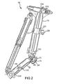
FIG. 2 , an internal view of articulatedlanding gear 100 is illustrated according to various embodiments.Structural post 110 may be at least partially hollow. In various embodiments, electrical lines and/orhydraulic lines 170 may be unsupported throughout at least one ofstructural post 110 and trailingarm 120. However, in various embodiments, electrical lines and/orhydraulic lines 170 may be supported by at least onebulkhead - In various embodiments,
bulkheads hydraulic lines 170 and prevent damage or failure from movement, such as vibrations. In various embodiments,bulkheads bulkheads bulkheads structural post 110 or trailingarm 120, contact betweenbulkheads structural post 110 or trailingarm 120 keepsbulkheads bulkheads bulkheads bulkheads bulkheads hydraulic lines 170 in order to keepbulkheads - In various embodiments, articulated
landing gear 100 may comprise a brace attachspindle pin 230. Brace attachspindle pin 230 may extend throughpin hole 212 ofbulkhead 210C in order to secure bulkhead 210 in place. Brace attachspindle pin 230 may couple a locking side brace actuator to the structure of articulatedlanding gear 100. The side brace actuator may lock in a gear down position to maintain articulatedlanding gear 100 in a down and locked position, and the side brace actuator may retract articulatedlanding gear 100 into an airframe. Articulatedlanding gear 100 may further comprisebrake pin bulkhead 210E.Brake pin bulkhead 210E may comprisebrake pin 218 which securesbrake pin bulkhead 210E in place.Brake pin 218 may prevent a brake from rotating about an axle in response to brake torque being applied. In various embodiments, brace attachspindle pin 230 and/orbrake pin 218 may support one ormore bulkheads 210A through 210F. - Trailing
arm 120 may comprise a reinforcedexit 220. Reinforcedexit 220 may be a hole in the wall of trailingarm 120 which allows electrical lines and/orhydraulic lines 170 to pass between an interior of trailingarm 120 and the exterior area aroundpivot joint 140. Reinforcedexit 220 may be environmentally sealed to prevent gas or fluids from entering or leaving trailingarm 120 through reinforcedexit 220. In various embodiments,structural post 110 may also comprise a reinforced exit nearbulkhead 210A. In various embodiments, the flexible portion of electrical lines and/orhydraulic lines 170 may be exposed to the elements between trailingarm 120 andstructural post 110. However, in various embodiments, articulatedlanding gear 100 may comprise adeflector 240 around pivot joint 140 which protects the flexible portion of electrical lines and/orhydraulic lines 170 and may reduce noise from turbulence caused by electrical lines and/orhydraulic lines 170. - Referring to
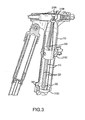
FIG. 3 , a perspective view of the interior ofstructural post 110 is illustrated according to various embodiments. As illustrated,structural post 110 comprises twoelectrical lines 310 and twohydraulic lines 320 in the interior ofstructural post 110. However,structural post 110 may comprise any number of electrical lines and hydraulic lines.Electrical lines 310 andhydraulic lines 320 pass throughguide holes 330 inbulkheads 210A through 210F. Guide holes 330 may prevent movement ofelectrical lines 310 andhydraulic lines 320 in order to prevent damage. In various embodiments, at least onebulkhead 210D may comprise anupper surface 340 which is slanted downward towards the center ofstructural post 110. The slantedupper surface 340 may allow fluids to drain throughstructural post 110 without accumulating onupper surface 340. - Referring to
FIG. 4 , trailingarm 120 is illustrated coupled toaxle 410 according to various embodiments. In various embodiments, electrical lines and/orhydraulic lines 170 may be rigid within trailingarm 120. In various embodiments, flexible electrical lines and/or hydraulic lines may be located withinaxle 410, and the flexible electrical lines and/or hydraulic lines may couple to electrical lines and/orhydraulic lines 170 atbulkhead 210F. - Benefits, other advantages, and solutions to problems have been described herein with regard to specific embodiments. Furthermore, the connecting lines shown in the various figures contained herein are intended to represent exemplary functional relationships and/or physical couplings between the various elements. It should be noted that many alternative or additional functional relationships or physical connections may be present in a practical system. However, the benefits, advantages, solutions to problems, and any elements that may cause any benefit, advantage, or solution to occur or become more pronounced are not to be construed as critical, required, or essential features or elements of the inventions. The scope of the inventions is accordingly to be limited by nothing other than the appended claims, in which reference to an element in the singular is not intended to mean "one and only one" unless explicitly so stated, but rather "one or more." Moreover, where a phrase similar to "at least one of A, B, or C" is used in the claims, it is intended that the phrase be interpreted to mean that A alone may be present in an embodiment, B alone may be present in an embodiment, C alone may be present in an embodiment, or that any combination of the elements A, B and C may be present in a single embodiment; for example, A and B, A and C, B and C, or A and B and C.
- Systems, methods and apparatus are provided herein. In the detailed description herein, references to "various embodiments", "one embodiment", "an embodiment", "an example embodiment", etc., indicate that the embodiment described may include a particular feature, structure, or characteristic, but every embodiment may not necessarily include the particular feature, structure, or characteristic. Moreover, such phrases are not necessarily referring to the same embodiment. Further, when a particular feature, structure, or characteristic is described in connection with an embodiment, it is submitted that it is within the knowledge of one skilled in the art to affect such feature, structure, or characteristic in connection with other embodiments whether or not explicitly described. After reading the description, it will be apparent to one skilled in the relevant art(s) how to implement the disclosure in alternative embodiments.
- Furthermore, no element, component, or method step in the present disclosure is intended to be dedicated to the public regardless of whether the element, component, or method step is explicitly recited in the claims. No claim element herein is to be construed under the provisions of 35 U.S.C. 112, sixth paragraph, unless the element is expressly recited using the phrase "means for." As used herein, the terms "comprises", "comprising", or any other variation thereof, are intended to cover a non-exclusive inclusion, such that a process, method, article, or apparatus that comprises a list of elements does not include only those elements but may include other elements not expressly listed or inherent to such process, method, article, or apparatus.
Claims (15)
- An articulated landing gear (100) comprising:a structural post (110);a trailing arm (120) coupled to the structural post (110); andat least one of an electrical line (310) and a hydraulic line (320; 170) located at least partially within the structural post (110) and the trailing arm (120).
- The articulated landing gear of claim 1, wherein the at least one of an electrical line (310) and a hydraulic line (320; 170) comprises a first portion located within the structural post (110), a second portion located between the structural post (110) and the trailing arm (120), and a third portion located within the trailing arm (120).
- The articulated landing gear of claim 2, wherein the first portion is rigid and the second portion is flexible.
- The articulated landing gear of any preceding claim, further comprising a bulkhead (210A-210F) located within at least one of the structural post (110) and the trailing arm (120).
- The articulated landing gear of claim 4, wherein the bulkhead (210A-210F) comprises a guide hole (330), and wherein the at least one of an electrical line (310) and a hydraulic line (320; 170) travels through the guide hole (330).
- The articulated landing gear of any preceding claim, wherein at least one of the trailing arm (120) and the structural post (110) comprises a reinforced exit (220), and/or wherein at least one of the structural post (110) and the trailing arm (120) comprises a hollow tube, and/or wherein an upper surface of a bulkhead located in the structural post (210D) slants downward toward a center of the structural post (110).
- A landing gear comprising:a hollow structural post (110);a first bulkhead (210A-210F) located within the hollow structural post (110); andat least one of an electrical line (310) and a hydraulic line (320; 170), wherein the at least one of an electrical line (310) and a hydraulic line (320;170) passes through a first guide hole (330) in the first bulkhead (210A-210F).
- The landing gear of claim 7, further comprising a hollow trailing arm (120) coupled to the hollow structural post (110).
- The landing gear of claim 8, wherein the hollow trailing arm (120) comprises a second bulkhead (210A-210F) located within the hollow trailing arm (120), wherein the at least one of an electrical line (310) and a hydraulic line (320; 170) passes through a second guide hole (330) in the second bulkhead (210A-210F).
- The landing gear of claim 8 or 9, wherein the at least one of an electrical line (310) and a hydraulic line (310;170) is exposed between the hollow structural post (110) and the hollow trailing arm (120).
- The landing gear of any preceding claim, wherein the at least one of an electrical line (310) and a hydraulic line (310;170) further comprises at least one electrical line (310) and at least one hydraulic line (310;170) passing through the first bulkhead (210A-210F), and/or wherein the first bulkhead (210A-210F) is secured to the hollow structural post (110) by a brace attach spindle pin (230).
- A system for routing at least one of an electrical line (310) and a hydraulic line (320;170) comprising:a structural post (110);a trailing arm (120) coupled to the structural post (110) at a pivot joint (140); anda bulkhead (210A-210F) located within at least one of the structural post (110) and the trailing arm (120); wherein the bulkhead (210A-210F) secures the at least one of an electrical line (310) and a hydraulic line (320; 170).
- The system of claim 12, wherein the at least one of an electrical line (310) and a hydraulic line (320; 170) comprises a first rigid portion located within the structural post (110), a flexible portion located around the pivot joint (140), and a second rigid portion located within the trailing arm (120).
- The system of claim 13, wherein the flexible portion is exposed around the pivot joint (140).
- The system of claim 13 or 14, further comprising a deflector which protects the flexible portion around the pivot joint (140).
Applications Claiming Priority (1)
| Application Number | Priority Date | Filing Date | Title |
|---|---|---|---|
| US13/957,765 US9284047B2 (en) | 2013-08-02 | 2013-08-02 | Routings for articulated landing gear |
Publications (2)
| Publication Number | Publication Date |
|---|---|
| EP2845798A1 true EP2845798A1 (en) | 2015-03-11 |
| EP2845798B1 EP2845798B1 (en) | 2019-04-10 |
Family
ID=50842153
Family Applications (1)
| Application Number | Title | Priority Date | Filing Date |
|---|---|---|---|
| EP14170821.4A Active EP2845798B1 (en) | 2013-08-02 | 2014-06-02 | Routings for articulated landing gear |
Country Status (2)
| Country | Link |
|---|---|
| US (1) | US9284047B2 (en) |
| EP (1) | EP2845798B1 (en) |
Families Citing this family (3)
| Publication number | Priority date | Publication date | Assignee | Title |
|---|---|---|---|---|
| EP3153404B1 (en) | 2015-10-06 | 2020-09-23 | Safran Landing Systems UK Limited | Aircraft assembly |
| EP3159260B1 (en) | 2015-10-23 | 2019-11-27 | Safran Landing Systems UK Limited | Aircraft landing gear assembly including a health and usage monitoring system (hums) and method |
| US10563690B2 (en) | 2016-07-28 | 2020-02-18 | Goodrich Corporation | Thin-skin side stay beams and landing gear assemblies |
Citations (5)
| Publication number | Priority date | Publication date | Assignee | Title |
|---|---|---|---|---|
| US3532307A (en) * | 1968-07-11 | 1970-10-06 | Fred Larson | Retractable landing gear without hydraulic means |
| WO2001004003A1 (en) * | 1999-07-08 | 2001-01-18 | Bae Systems Plc | Aircraft noise reduction apparatus |
| EP1382526A1 (en) * | 2002-07-15 | 2004-01-21 | SP Aerospace and Vehicle Systems B.V. | Aircraft noise reduction device |
| WO2012004594A1 (en) * | 2010-07-06 | 2012-01-12 | Ultra Electronics Limited | Linkage for guiding a flexible cable |
| WO2012080426A1 (en) * | 2010-12-16 | 2012-06-21 | Messier-Bugatti-Dowty | Device for guiding and holding a cable within a pipe |
Family Cites Families (35)
| Publication number | Priority date | Publication date | Assignee | Title |
|---|---|---|---|---|
| US2318568A (en) * | 1940-03-15 | 1943-05-04 | Ohio Commw Eng Co | Hydraulic landing gear |
| US2587628A (en) * | 1949-01-24 | 1952-03-04 | Harold B King | Load stroke indicator |
| US3273382A (en) * | 1963-08-20 | 1966-09-20 | Raymond L Fonash | Apparatus to determine horizontal and vertical loads in landing gear of aircraft |
| US3401388A (en) * | 1966-12-27 | 1968-09-10 | Ryan Aeronautical Co | Closure-rate determining radar system |
| US3517550A (en) * | 1968-05-08 | 1970-06-30 | Us Navy | Load and rate of change of load detection system |
| US3712122A (en) * | 1971-02-08 | 1973-01-23 | Electro Dev Corp | Aircraft hard landing indicator |
| US3946358A (en) * | 1974-06-19 | 1976-03-23 | Sundstrand Data Control, Inc. | Aircraft ground proximity warning instrument |
| FR2417433A1 (en) * | 1978-02-20 | 1979-09-14 | France Etat | MECHANICAL DEVICE FOR DETECTION OF HARD LANDINGS |
| US4302827A (en) * | 1980-04-08 | 1981-11-24 | Rosenblum Arthur B | Runway and obstacle detector to improve airplane landing |
| DE3228557A1 (en) * | 1982-07-30 | 1984-02-09 | Ulrich 8000 München Trampnau | WARNING DEVICE FOR HELICOPTER |
| US4770372A (en) * | 1986-09-30 | 1988-09-13 | The Boeing Company | Two-stage aircraft landing gear |
| US4869444A (en) * | 1986-09-30 | 1989-09-26 | The Boeing Company | Adjustable two-stage aircraft landing gear system |
| US4979154A (en) * | 1989-01-10 | 1990-12-18 | Lester Brodeur | Landing aid for aircraft |
| US5260702A (en) * | 1989-12-27 | 1993-11-09 | Thompson Keith P | Aircraft information system |
| US5406487A (en) * | 1991-10-11 | 1995-04-11 | Tanis; Peter G. | Aircraft altitude approach control device |
| US5214586A (en) * | 1992-02-07 | 1993-05-25 | Nance C Kirk | Aircraft weight and center of gravity indicator |
| DE69312687T2 (en) * | 1992-02-07 | 1998-02-26 | C. Kirk Arlington Tex. Nance | INDICATORS OF WEIGHT AND FOCUS ON AIRCRAFT |
| FR2713193B1 (en) * | 1993-12-06 | 1996-01-26 | Aerospatiale | Method and device for detecting that the design loads of an aircraft have been exceeded. |
| US6128951A (en) * | 1997-04-15 | 2000-10-10 | Trinity Airweighs, L.L.C. | Aircraft weight and center of gravity indicator |
| US6012001A (en) * | 1997-12-30 | 2000-01-04 | Scully; Robert L. | Method and apparatus for determining aircraft-to-ground distances and descent rates during landing |
| US6588282B2 (en) * | 1998-03-04 | 2003-07-08 | Microstrain, Inc. | Peak strain detection linear displacement sensor system for smart structures |
| US6024145A (en) * | 1998-04-08 | 2000-02-15 | Ackles; Gary | Articulated boom and head for manipulating objects under water |
| US6676075B2 (en) * | 2001-08-30 | 2004-01-13 | The Boeing Company | Airplane hard landing indication system |
| JP2005059656A (en) * | 2003-08-08 | 2005-03-10 | Fuji Heavy Ind Ltd | Flying object landing control device and flying object landing control method |
| US7274310B1 (en) * | 2005-03-29 | 2007-09-25 | Nance C Kirk | Aircraft landing gear kinetic energy monitor |
| CA2509742A1 (en) * | 2005-06-10 | 2006-12-10 | Messier-Dowty Inc. | System and method for determining aircraft hard landing events from inertial and aircraft reference frame data |
| GB0704878D0 (en) * | 2007-03-14 | 2007-04-18 | Trw Ltd | Aircraft landing gear monitoring apparatus |
| US7944372B2 (en) * | 2008-04-18 | 2011-05-17 | The Boeing Company | Aircraft tip alarm system |
| US8042765B1 (en) * | 2008-05-20 | 2011-10-25 | Nance C Kirk | Aircraft landing gear compression rate monitor |
| US8091481B1 (en) * | 2009-05-01 | 2012-01-10 | Floyd Brian A | Gas strut separation for staged rocket |
| US8180504B1 (en) * | 2009-05-21 | 2012-05-15 | Nance C Kirk | Aircraft landing gear compression rate monitor and method to increase aircraft landing weight limitation |
| US8903572B1 (en) * | 2009-08-11 | 2014-12-02 | The Boeing Company | Aircraft landing evaluation system |
| EP2397406B1 (en) * | 2010-06-14 | 2019-08-07 | Airbus Defence and Space SA | Pin bearing arrangement for aircraft landing gear |
| US8565968B2 (en) * | 2010-08-31 | 2013-10-22 | C. Kirk Nance | Automated inspection of aircraft landing gear internal fluid levels |
| US8565965B2 (en) * | 2011-04-01 | 2013-10-22 | C. Kirk Nance | Aircraft landing gear automated inspection for presence of internal oxygen contamination |
-
2013
- 2013-08-02 US US13/957,765 patent/US9284047B2/en active Active
-
2014
- 2014-06-02 EP EP14170821.4A patent/EP2845798B1/en active Active
Patent Citations (5)
| Publication number | Priority date | Publication date | Assignee | Title |
|---|---|---|---|---|
| US3532307A (en) * | 1968-07-11 | 1970-10-06 | Fred Larson | Retractable landing gear without hydraulic means |
| WO2001004003A1 (en) * | 1999-07-08 | 2001-01-18 | Bae Systems Plc | Aircraft noise reduction apparatus |
| EP1382526A1 (en) * | 2002-07-15 | 2004-01-21 | SP Aerospace and Vehicle Systems B.V. | Aircraft noise reduction device |
| WO2012004594A1 (en) * | 2010-07-06 | 2012-01-12 | Ultra Electronics Limited | Linkage for guiding a flexible cable |
| WO2012080426A1 (en) * | 2010-12-16 | 2012-06-21 | Messier-Bugatti-Dowty | Device for guiding and holding a cable within a pipe |
Also Published As
| Publication number | Publication date |
|---|---|
| US20150034762A1 (en) | 2015-02-05 |
| EP2845798B1 (en) | 2019-04-10 |
| US9284047B2 (en) | 2016-03-15 |
Similar Documents
| Publication | Publication Date | Title |
|---|---|---|
| US9284047B2 (en) | Routings for articulated landing gear | |
| US8640988B2 (en) | Landing gear with composite leaf spring | |
| EP2590857B1 (en) | Linkage for guiding a flexible cable | |
| BR112017002597B1 (en) | Downhole wireless transfer system and method | |
| CA2665895A1 (en) | Loading system | |
| EP3247623B1 (en) | Ship with a telescopic gangway for transferring individuals between the ship and a stationary or near-stationary object at sea, such as a wind turbine | |
| BR0300993B1 (en) | SUBMARINE RELEASEABLE DRUM FOR DUTY SETTING | |
| US20190002092A1 (en) | Aircraft landing gear assembly | |
| EP2848480B1 (en) | Reinforced electromechanical actuator housing | |
| EP2969771B1 (en) | Swing down mount for helicopter and method for operating same | |
| US20190002089A1 (en) | Pitch trimmer | |
| EP3051148A1 (en) | Actuator with a composite piston rod and a metallic piston | |
| NO20150903A1 (en) | Method and systems for maintaining a functional line for conveying fluid and pig assemblies for use therein | |
| CA2802451C (en) | Pin bearing arrangement for aircraft landing gear | |
| CN209905104U (en) | Universal satellite adapter structure | |
| CN102070085A (en) | Method for butting flange faces by using butting device | |
| CN104787312A (en) | Cross beam structure of skid landing gear | |
| DK178996B1 (en) | Transport device | |
| US20190106095A1 (en) | Brake control system channel protection | |
| EP3351474A1 (en) | Landing gear folding brace with locking actuator | |
| CN216112799U (en) | Pipeline Robot and Pipeline Inspection Device | |
| CN110873258B (en) | Inner wall detection device and inner wall detection system | |
| EP3722627B1 (en) | Hybrid metallic/composite joint with integral bearing | |
| US20160097468A1 (en) | Apparatus for launch and recovery of flexible hose and method of use | |
| EP2862801A1 (en) | Integral clamp hubcap for wheel system and apparatus |
Legal Events
| Date | Code | Title | Description |
|---|---|---|---|
| 17P | Request for examination filed |
Effective date: 20140602 |
|
| AK | Designated contracting states |
Kind code of ref document: A1 Designated state(s): AL AT BE BG CH CY CZ DE DK EE ES FI FR GB GR HR HU IE IS IT LI LT LU LV MC MK MT NL NO PL PT RO RS SE SI SK SM TR |
|
| AX | Request for extension of the european patent |
Extension state: BA ME |
|
| PUAI | Public reference made under article 153(3) epc to a published international application that has entered the european phase |
Free format text: ORIGINAL CODE: 0009012 |
|
| R17P | Request for examination filed (corrected) |
Effective date: 20150904 |
|
| RBV | Designated contracting states (corrected) |
Designated state(s): AL AT BE BG CH CY CZ DE DK EE ES FI FR GB GR HR HU IE IS IT LI LT LU LV MC MK MT NL NO PL PT RO RS SE SI SK SM TR |
|
| STAA | Information on the status of an ep patent application or granted ep patent |
Free format text: STATUS: EXAMINATION IS IN PROGRESS |
|
| 17Q | First examination report despatched |
Effective date: 20171213 |
|
| GRAP | Despatch of communication of intention to grant a patent |
Free format text: ORIGINAL CODE: EPIDOSNIGR1 |
|
| STAA | Information on the status of an ep patent application or granted ep patent |
Free format text: STATUS: GRANT OF PATENT IS INTENDED |
|
| RIC1 | Information provided on ipc code assigned before grant |
Ipc: B64C 25/02 20060101ALI20181002BHEP Ipc: B64C 25/00 20060101AFI20181002BHEP |
|
| INTG | Intention to grant announced |
Effective date: 20181026 |
|
| GRAS | Grant fee paid |
Free format text: ORIGINAL CODE: EPIDOSNIGR3 |
|
| GRAA | (expected) grant |
Free format text: ORIGINAL CODE: 0009210 |
|
| STAA | Information on the status of an ep patent application or granted ep patent |
Free format text: STATUS: THE PATENT HAS BEEN GRANTED |
|
| AK | Designated contracting states |
Kind code of ref document: B1 Designated state(s): AL AT BE BG CH CY CZ DE DK EE ES FI FR GB GR HR HU IE IS IT LI LT LU LV MC MK MT NL NO PL PT RO RS SE SI SK SM TR |
|
| REG | Reference to a national code |
Ref country code: GB Ref legal event code: FG4D |
|
| REG | Reference to a national code |
Ref country code: CH Ref legal event code: EP Ref country code: AT Ref legal event code: REF Ref document number: 1118307 Country of ref document: AT Kind code of ref document: T Effective date: 20190415 |
|
| REG | Reference to a national code |
Ref country code: IE Ref legal event code: FG4D |
|
| REG | Reference to a national code |
Ref country code: DE Ref legal event code: R096 Ref document number: 602014044316 Country of ref document: DE |
|
| REG | Reference to a national code |
Ref country code: NL Ref legal event code: MP Effective date: 20190410 |
|
| REG | Reference to a national code |
Ref country code: LT Ref legal event code: MG4D |
|
| REG | Reference to a national code |
Ref country code: AT Ref legal event code: MK05 Ref document number: 1118307 Country of ref document: AT Kind code of ref document: T Effective date: 20190410 |
|
| PG25 | Lapsed in a contracting state [announced via postgrant information from national office to epo] |
Ref country code: NL Free format text: LAPSE BECAUSE OF FAILURE TO SUBMIT A TRANSLATION OF THE DESCRIPTION OR TO PAY THE FEE WITHIN THE PRESCRIBED TIME-LIMIT Effective date: 20190410 |
|
| PG25 | Lapsed in a contracting state [announced via postgrant information from national office to epo] |
Ref country code: ES Free format text: LAPSE BECAUSE OF FAILURE TO SUBMIT A TRANSLATION OF THE DESCRIPTION OR TO PAY THE FEE WITHIN THE PRESCRIBED TIME-LIMIT Effective date: 20190410 Ref country code: AL Free format text: LAPSE BECAUSE OF FAILURE TO SUBMIT A TRANSLATION OF THE DESCRIPTION OR TO PAY THE FEE WITHIN THE PRESCRIBED TIME-LIMIT Effective date: 20190410 Ref country code: SE Free format text: LAPSE BECAUSE OF FAILURE TO SUBMIT A TRANSLATION OF THE DESCRIPTION OR TO PAY THE FEE WITHIN THE PRESCRIBED TIME-LIMIT Effective date: 20190410 Ref country code: HR Free format text: LAPSE BECAUSE OF FAILURE TO SUBMIT A TRANSLATION OF THE DESCRIPTION OR TO PAY THE FEE WITHIN THE PRESCRIBED TIME-LIMIT Effective date: 20190410 Ref country code: LT Free format text: LAPSE BECAUSE OF FAILURE TO SUBMIT A TRANSLATION OF THE DESCRIPTION OR TO PAY THE FEE WITHIN THE PRESCRIBED TIME-LIMIT Effective date: 20190410 Ref country code: NO Free format text: LAPSE BECAUSE OF FAILURE TO SUBMIT A TRANSLATION OF THE DESCRIPTION OR TO PAY THE FEE WITHIN THE PRESCRIBED TIME-LIMIT Effective date: 20190710 Ref country code: FI Free format text: LAPSE BECAUSE OF FAILURE TO SUBMIT A TRANSLATION OF THE DESCRIPTION OR TO PAY THE FEE WITHIN THE PRESCRIBED TIME-LIMIT Effective date: 20190410 Ref country code: PT Free format text: LAPSE BECAUSE OF FAILURE TO SUBMIT A TRANSLATION OF THE DESCRIPTION OR TO PAY THE FEE WITHIN THE PRESCRIBED TIME-LIMIT Effective date: 20190910 |
|
| PG25 | Lapsed in a contracting state [announced via postgrant information from national office to epo] |
Ref country code: RS Free format text: LAPSE BECAUSE OF FAILURE TO SUBMIT A TRANSLATION OF THE DESCRIPTION OR TO PAY THE FEE WITHIN THE PRESCRIBED TIME-LIMIT Effective date: 20190410 Ref country code: PL Free format text: LAPSE BECAUSE OF FAILURE TO SUBMIT A TRANSLATION OF THE DESCRIPTION OR TO PAY THE FEE WITHIN THE PRESCRIBED TIME-LIMIT Effective date: 20190410 Ref country code: BG Free format text: LAPSE BECAUSE OF FAILURE TO SUBMIT A TRANSLATION OF THE DESCRIPTION OR TO PAY THE FEE WITHIN THE PRESCRIBED TIME-LIMIT Effective date: 20190710 Ref country code: GR Free format text: LAPSE BECAUSE OF FAILURE TO SUBMIT A TRANSLATION OF THE DESCRIPTION OR TO PAY THE FEE WITHIN THE PRESCRIBED TIME-LIMIT Effective date: 20190711 Ref country code: LV Free format text: LAPSE BECAUSE OF FAILURE TO SUBMIT A TRANSLATION OF THE DESCRIPTION OR TO PAY THE FEE WITHIN THE PRESCRIBED TIME-LIMIT Effective date: 20190410 |
|
| PG25 | Lapsed in a contracting state [announced via postgrant information from national office to epo] |
Ref country code: IS Free format text: LAPSE BECAUSE OF FAILURE TO SUBMIT A TRANSLATION OF THE DESCRIPTION OR TO PAY THE FEE WITHIN THE PRESCRIBED TIME-LIMIT Effective date: 20190810 Ref country code: AT Free format text: LAPSE BECAUSE OF FAILURE TO SUBMIT A TRANSLATION OF THE DESCRIPTION OR TO PAY THE FEE WITHIN THE PRESCRIBED TIME-LIMIT Effective date: 20190410 |
|
| REG | Reference to a national code |
Ref country code: DE Ref legal event code: R119 Ref document number: 602014044316 Country of ref document: DE |
|
| PG25 | Lapsed in a contracting state [announced via postgrant information from national office to epo] |
Ref country code: DK Free format text: LAPSE BECAUSE OF FAILURE TO SUBMIT A TRANSLATION OF THE DESCRIPTION OR TO PAY THE FEE WITHIN THE PRESCRIBED TIME-LIMIT Effective date: 20190410 Ref country code: MC Free format text: LAPSE BECAUSE OF FAILURE TO SUBMIT A TRANSLATION OF THE DESCRIPTION OR TO PAY THE FEE WITHIN THE PRESCRIBED TIME-LIMIT Effective date: 20190410 Ref country code: SK Free format text: LAPSE BECAUSE OF FAILURE TO SUBMIT A TRANSLATION OF THE DESCRIPTION OR TO PAY THE FEE WITHIN THE PRESCRIBED TIME-LIMIT Effective date: 20190410 Ref country code: RO Free format text: LAPSE BECAUSE OF FAILURE TO SUBMIT A TRANSLATION OF THE DESCRIPTION OR TO PAY THE FEE WITHIN THE PRESCRIBED TIME-LIMIT Effective date: 20190410 Ref country code: EE Free format text: LAPSE BECAUSE OF FAILURE TO SUBMIT A TRANSLATION OF THE DESCRIPTION OR TO PAY THE FEE WITHIN THE PRESCRIBED TIME-LIMIT Effective date: 20190410 Ref country code: CZ Free format text: LAPSE BECAUSE OF FAILURE TO SUBMIT A TRANSLATION OF THE DESCRIPTION OR TO PAY THE FEE WITHIN THE PRESCRIBED TIME-LIMIT Effective date: 20190410 |
|
| REG | Reference to a national code |
Ref country code: CH Ref legal event code: PL |
|
| PLBE | No opposition filed within time limit |
Free format text: ORIGINAL CODE: 0009261 |
|
| STAA | Information on the status of an ep patent application or granted ep patent |
Free format text: STATUS: NO OPPOSITION FILED WITHIN TIME LIMIT |
|
| PG25 | Lapsed in a contracting state [announced via postgrant information from national office to epo] |
Ref country code: IT Free format text: LAPSE BECAUSE OF FAILURE TO SUBMIT A TRANSLATION OF THE DESCRIPTION OR TO PAY THE FEE WITHIN THE PRESCRIBED TIME-LIMIT Effective date: 20190410 Ref country code: SM Free format text: LAPSE BECAUSE OF FAILURE TO SUBMIT A TRANSLATION OF THE DESCRIPTION OR TO PAY THE FEE WITHIN THE PRESCRIBED TIME-LIMIT Effective date: 20190410 |
|
| 26N | No opposition filed |
Effective date: 20200113 |
|
| REG | Reference to a national code |
Ref country code: BE Ref legal event code: MM Effective date: 20190630 |
|
| PG25 | Lapsed in a contracting state [announced via postgrant information from national office to epo] |
Ref country code: TR Free format text: LAPSE BECAUSE OF FAILURE TO SUBMIT A TRANSLATION OF THE DESCRIPTION OR TO PAY THE FEE WITHIN THE PRESCRIBED TIME-LIMIT Effective date: 20190410 |
|
| PG25 | Lapsed in a contracting state [announced via postgrant information from national office to epo] |
Ref country code: IE Free format text: LAPSE BECAUSE OF NON-PAYMENT OF DUE FEES Effective date: 20190602 Ref country code: DE Free format text: LAPSE BECAUSE OF NON-PAYMENT OF DUE FEES Effective date: 20200101 |
|
| PG25 | Lapsed in a contracting state [announced via postgrant information from national office to epo] |
Ref country code: BE Free format text: LAPSE BECAUSE OF NON-PAYMENT OF DUE FEES Effective date: 20190630 Ref country code: LI Free format text: LAPSE BECAUSE OF NON-PAYMENT OF DUE FEES Effective date: 20190630 Ref country code: CH Free format text: LAPSE BECAUSE OF NON-PAYMENT OF DUE FEES Effective date: 20190630 Ref country code: LU Free format text: LAPSE BECAUSE OF NON-PAYMENT OF DUE FEES Effective date: 20190602 Ref country code: SI Free format text: LAPSE BECAUSE OF FAILURE TO SUBMIT A TRANSLATION OF THE DESCRIPTION OR TO PAY THE FEE WITHIN THE PRESCRIBED TIME-LIMIT Effective date: 20190410 |
|
| PG25 | Lapsed in a contracting state [announced via postgrant information from national office to epo] |
Ref country code: CY Free format text: LAPSE BECAUSE OF FAILURE TO SUBMIT A TRANSLATION OF THE DESCRIPTION OR TO PAY THE FEE WITHIN THE PRESCRIBED TIME-LIMIT Effective date: 20190410 |
|
| PG25 | Lapsed in a contracting state [announced via postgrant information from national office to epo] |
Ref country code: HU Free format text: LAPSE BECAUSE OF FAILURE TO SUBMIT A TRANSLATION OF THE DESCRIPTION OR TO PAY THE FEE WITHIN THE PRESCRIBED TIME-LIMIT; INVALID AB INITIO Effective date: 20140602 Ref country code: MT Free format text: LAPSE BECAUSE OF FAILURE TO SUBMIT A TRANSLATION OF THE DESCRIPTION OR TO PAY THE FEE WITHIN THE PRESCRIBED TIME-LIMIT Effective date: 20190410 |
|
| PG25 | Lapsed in a contracting state [announced via postgrant information from national office to epo] |
Ref country code: MK Free format text: LAPSE BECAUSE OF FAILURE TO SUBMIT A TRANSLATION OF THE DESCRIPTION OR TO PAY THE FEE WITHIN THE PRESCRIBED TIME-LIMIT Effective date: 20190410 |
|
| P01 | Opt-out of the competence of the unified patent court (upc) registered |
Effective date: 20230522 |
|
| PGFP | Annual fee paid to national office [announced via postgrant information from national office to epo] |
Ref country code: GB Payment date: 20250520 Year of fee payment: 12 |
|
| PGFP | Annual fee paid to national office [announced via postgrant information from national office to epo] |
Ref country code: FR Payment date: 20250520 Year of fee payment: 12 |