EP2845574B1 - Incubator - Google Patents
Incubator Download PDFInfo
- Publication number
- EP2845574B1 EP2845574B1 EP14192302.9A EP14192302A EP2845574B1 EP 2845574 B1 EP2845574 B1 EP 2845574B1 EP 14192302 A EP14192302 A EP 14192302A EP 2845574 B1 EP2845574 B1 EP 2845574B1
- Authority
- EP
- European Patent Office
- Prior art keywords
- chamber
- ventilator
- circulation device
- air
- incubator
- Prior art date
- Legal status (The legal status is an assumption and is not a legal conclusion. Google has not performed a legal analysis and makes no representation as to the accuracy of the status listed.)
- Active
Links
- 230000007704 transition Effects 0.000 claims description 4
- 239000012530 fluid Substances 0.000 description 3
- 238000010438 heat treatment Methods 0.000 description 3
- XLYOFNOQVPJJNP-UHFFFAOYSA-N water Substances O XLYOFNOQVPJJNP-UHFFFAOYSA-N 0.000 description 2
- 238000010276 construction Methods 0.000 description 1
- 230000008878 coupling Effects 0.000 description 1
- 238000010168 coupling process Methods 0.000 description 1
- 238000005859 coupling reaction Methods 0.000 description 1
- 230000036642 wellbeing Effects 0.000 description 1
Images
Classifications
-
- A—HUMAN NECESSITIES
- A61—MEDICAL OR VETERINARY SCIENCE; HYGIENE
- A61G—TRANSPORT, PERSONAL CONVEYANCES, OR ACCOMMODATION SPECIALLY ADAPTED FOR PATIENTS OR DISABLED PERSONS; OPERATING TABLES OR CHAIRS; CHAIRS FOR DENTISTRY; FUNERAL DEVICES
- A61G11/00—Baby-incubators; Couveuses
-
- A—HUMAN NECESSITIES
- A61—MEDICAL OR VETERINARY SCIENCE; HYGIENE
- A61M—DEVICES FOR INTRODUCING MEDIA INTO, OR ONTO, THE BODY; DEVICES FOR TRANSDUCING BODY MEDIA OR FOR TAKING MEDIA FROM THE BODY; DEVICES FOR PRODUCING OR ENDING SLEEP OR STUPOR
- A61M16/00—Devices for influencing the respiratory system of patients by gas treatment, e.g. mouth-to-mouth respiration; Tracheal tubes
- A61M16/10—Preparation of respiratory gases or vapours
-
- F—MECHANICAL ENGINEERING; LIGHTING; HEATING; WEAPONS; BLASTING
- F24—HEATING; RANGES; VENTILATING
- F24F—AIR-CONDITIONING; AIR-HUMIDIFICATION; VENTILATION; USE OF AIR CURRENTS FOR SCREENING
- F24F13/00—Details common to, or for air-conditioning, air-humidification, ventilation or use of air currents for screening
- F24F13/24—Means for preventing or suppressing noise
-
- F—MECHANICAL ENGINEERING; LIGHTING; HEATING; WEAPONS; BLASTING
- F24—HEATING; RANGES; VENTILATING
- F24F—AIR-CONDITIONING; AIR-HUMIDIFICATION; VENTILATION; USE OF AIR CURRENTS FOR SCREENING
- F24F13/00—Details common to, or for air-conditioning, air-humidification, ventilation or use of air currents for screening
- F24F13/08—Air-flow control members, e.g. louvres, grilles, flaps or guide plates
- F24F13/082—Grilles, registers or guards
- F24F2013/088—Air-flow straightener
Definitions
- the present invention relates to an incubator according to the preamble of claim 1.
- Such incubators are used in neonatology for intensive care of newborns, possibly prematurely born.
- Such an incubator is for example known from EP 1520572 .
- This known incubator has an air make-up compartment including a fan compartment and an air make-up channel that guides the air from the fan compartment to a delivery channel that runs underneath lateral side areas of the patient-support surface.
- the air delivery channel is in fluid communication with the patient space through vents located on the lateral sides of the deck of the device.
- the air make-up channel downstream of the fan compartment is provided with heating elements and possibly with a humidifier. Furthermore the air delivery channel is formed with right angled bends.
- a problem with known incubators is the noise that the ventilator of the air treatment and circulation device makes, which disturbs the infant and which may cause stress and other negative effects on the infants well-being and development.
- the invention has for an object to provide an incubator in which this problem is mitigated.
- the distribution chamber distributes the air flowing out of the ventilator to the chamber inlet openings and is designed to reduce the air speed.
- the distribution chamber is defined by a substantially flat upper wall of the housing and a flat bottom wall of the housing extending parallel thereto. This particular configuration of the upper wall and bottom wall prevents that the air flow runs into obstructions during its travel from the ventilator to the chamber inlets.
- the upper wall and bottom wall have on their longitudinal sides and at least one of their transversal sides an upwardly extending edge portion, wherein the associated edge portions between them define outlet ducts, wherein the free end of the outlet ducts is at least partly open, thereby defining the chamber inlet openings.
- the upwardly extending edge portions are curved. The particular shape of the housing prevents obstacles and tight turns which could create additional pressure losses.
- the outlet ducts are closed at their side ends by edge walls interconnecting the upper wall and bottom wall.
- a Venturi hump is arranged at the transition between the ventilator chamber and the distribution chamber.
- This Venturi hump creates a narrow gap through which the airflow locally accelerates.
- the created pressure differential over this hump balances the volume flow over the entire width of the Venturi hump such that all chamber inlet openings towards the chamber receive a certain amount of air.
- This effect is analogue to a water dam in a river which damps out dynamic effects.
- Venturi hump extends in a curved manner over the bottom wall, preferably in circular manner, thus with a constant radius of curvature.
- the air flow over the hump is equally distributed in the directions of the respective outlet ducts and the associated chamber inlets.
- the ventilator chamber and the distribution chamber and the outlet ducts are defined by one integral casing. In this way a compact and low complex ducting construction can be achieved. No couplings and transition parts are necessary between the different chambers and ducts and therefore a ducting system with a smooth inner surface is provided in which the air flow is disturbed as little as possible.
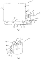
- FIG. 1 an incubator 1 for neonatology.
- the incubator 1 has an incubator chamber 2 which is defined by a casing 3 and a bottom part 4.
- the bottom part 4 supports a bed portion 5 on which the infant lies.
- the incubator 1 furthermore has an air treatment and circulation device 6.
- the air treatment and circulation device includes a ventilator unit 7, an inlet duct 8 and an outlet ducting assembly 9.
- the inlet duct may be of tubular shape with for example a substantially circular cross section.
- the inlet duct 8 is in fluid communication with the incubator chamber 2 through a chamber air outlet 10.
- the inlet duct 8 is connected at its other end connected with the ventilator unit 7. At this end the inlet duct 8 has an end portion which forms a constriction 11, which means that said end portion of the inlet duct 8 narrows towards the ventilator unit 7.
- the ventilator unit 7 comprises a centrifugal ventilator.
- the air flows towards the centrifugal ventilator in axial direction and exits in a radial direction.
- baffle unit 12 In the inlet duct 8 between the constriction 11 and the chamber outlet opening 10 is arranged a baffle unit 12.
- the baffle unit 12 is shown in more detail in Fig. 2 .
- the baffle unit 12 has a tubular portion 13.
- the baffling unit 12 has air guiding vanes 14, in this specific embodiment shown, it has four vanes 14 which are attached to the inner side of the tubular portion 13 and extend therefrom radially inwards towards a centre part 15.
- the vanes 14 are connected to the centre part 15.
- the centre part 15 has on its end facing the chamber outlet an inlet cone 16.
- the cylindrical portion 13 has on its outer side a support 17.
- the support 17 is in the mounted state (see Fig. 1 ) attached to the wall of the inlet duct 8.
- heater elements are provided in the cylindrical portion 13 and the radial vanes 14 of the baffle unit 12.
- the heater elements are connected with external heating components through the connections 18 in the support 17.
- the baffle unit 12 is attached to the wall of the inlet duct 8 by means of screws that are inserted in the screw holes 19.
- the support 17 has a sort of vane shape and has only a small contact area with the wall of the inlet duct 8. Thereby heat loss through the support 17 to the wall of inlet duct 8 is reduced. This reduces in use the response time of the heating system.
- the baffle unit 12 inside the inlet duct 8, through which air is fed to the ventilator unit 7, generates a more homogeneous flow with less turbulence compared to the situation where no baffle unit is present.
- baffle unit 12 and the constriction 11 downstream thereof both condition the air flow in such a way that they both improve each others functionality.
- a combination of a baffle unit 12 with a constriction 11 is therefore advantageous and it provides a low turbulence homogeneous feed flow towards the ventilator 7, which causes the ventilator 7 to generate less noise. This effect is with the specific configuration of the baffle unit 12 shown in the figures in particular achieved with a centrifugal ventilator.
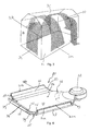
- a housing 20 for the air treatment and circulation device including its associated ducting system.
- the housing 20 defines a ventilator chamber 21 where the ventilator unit 7 is located.
- the ventilator chamber 21 has an inlet opening 22 through which the ventilator chamber 21 is in fluid communication with the inlet duct 8.
- the housing 20 furthermore defines a distribution chamber 23.
- the housing 20 has a substantially flat upper wall 24 and a flat bottom wall 25 extending parallel thereto which define the upper and bottom wall of the distribution chamber 23.
- the upper wall 24 and bottom wall 25 respectively have on their longitudinal sides an upwardly extending curved edge portion 26 and 27 respectively.
- the associated edge portions 26, 27 between them define outlet ducts 28 as can be seen in the sectional view in Fig 1 .
- the outlet ducts 28 are closed at their side ends by edge walls 29 interconnecting the upper wall 24 and bottom wall 25.
- the free end of the outlet ducts 28 is partly closed by a wall portion 30a and 30b.
- the remaining open portion of the free end of the outlet ducts 28 define chamber inlet openings 31 a, 31 b through which air can flow from the ducting system 9 to the incubator chamber 2.
- the ventilator is arranged on the head end side of the incubator.
- the upper wall 24 and bottom wall 25, respectively On the transverse side opposite where the ventilator chamber is located the upper wall 24 and bottom wall 25, respectively, have an upwardly extending curved edge portion 32 and 33 respectively. At the free end of these curved wall portions 32, 33 a chamber inlet opening 34 is defined.
- Venturi hump 35 is provided on the bottom wall 25.
- the Venturi hump 35 extends in a curved, preferably circular arch, shape as is clearly visible in Fig. 4 .
- This Venturi hump 35 creates a narrow gap between the bottom and the top wall through which the airflow locally accelerates.
- the created pressure differential over this hump 35 balances the volume flow over the entire width of the Venturi hump 35 such that all inlet openings 31 a, 31 b, 34 towards the incubator chamber 2 receive a certain amount of air.
- This effect is analogue to a water dam in a river which damps out dynamic effects. Without this measure the dynamics added to the flow by the ventilator 7 will cause most air exiting through opening 34, and almost none through openings 31 a, 31 b.
- Fig. 3 is shown how the air flows are directed through the incubator chamber 2.
- the inlets 31a, 31b and 34 and the outlet 10 are schematically indicated.
- the asymmetric routing prevents collision of the flow in the centre of the chamber top 3c, which is an advantage for keeping both the temperature stability and the required low airspeeds near the infant.
- the flow exiting from the inlet 34 is relatively weak in order not to disturb the flows originating from the inlets 31 a, 31 b at the longitudinal sides.
Description
- The present invention relates to an incubator according to the preamble of claim 1.
- Such incubators are used in neonatology for intensive care of newborns, possibly prematurely born. Such an incubator is for example known from
EP 1520572 . This known incubator has an air make-up compartment including a fan compartment and an air make-up channel that guides the air from the fan compartment to a delivery channel that runs underneath lateral side areas of the patient-support surface. The air delivery channel is in fluid communication with the patient space through vents located on the lateral sides of the deck of the device. The air make-up channel downstream of the fan compartment is provided with heating elements and possibly with a humidifier. Furthermore the air delivery channel is formed with right angled bends.
A problem with known incubators is the noise that the ventilator of the air treatment and circulation device makes, which disturbs the infant and which may cause stress and other negative effects on the infants well-being and development. - The invention has for an object to provide an incubator in which this problem is mitigated.
- According to the invention this object is achieved by an incubator according to claim 1.
- The distribution chamber distributes the air flowing out of the ventilator to the chamber inlet openings and is designed to reduce the air speed.
- According to the invention, the distribution chamber is defined by a substantially flat upper wall of the housing and a flat bottom wall of the housing extending parallel thereto. This particular configuration of the upper wall and bottom wall prevents that the air flow runs into obstructions during its travel from the ventilator to the chamber inlets.
- Preferably, the upper wall and bottom wall have on their longitudinal sides and at least one of their transversal sides an upwardly extending edge portion, wherein the associated edge portions between them define outlet ducts, wherein the free end of the outlet ducts is at least partly open, thereby defining the chamber inlet openings. Preferably, the upwardly extending edge portions are curved. The particular shape of the housing prevents obstacles and tight turns which could create additional pressure losses.
- The outlet ducts are closed at their side ends by edge walls interconnecting the upper wall and bottom wall.
- In a particularly advantageous embodiment a Venturi hump is arranged at the transition between the ventilator chamber and the distribution chamber. This Venturi hump creates a narrow gap through which the airflow locally accelerates. The created pressure differential over this hump balances the volume flow over the entire width of the Venturi hump such that all chamber inlet openings towards the chamber receive a certain amount of air. This effect is analogue to a water dam in a river which damps out dynamic effects.
- Preferably the Venturi hump extends in a curved manner over the bottom wall, preferably in circular manner, thus with a constant radius of curvature. Thereby the air flow over the hump is equally distributed in the directions of the respective outlet ducts and the associated chamber inlets.
- In a possible embodiment the ventilator chamber and the distribution chamber and the outlet ducts are defined by one integral casing. In this way a compact and low complex ducting construction can be achieved. No couplings and transition parts are necessary between the different chambers and ducts and therefore a ducting system with a smooth inner surface is provided in which the air flow is disturbed as little as possible.
- The invention will be further elucidated in the following detailed description with reference to the drawings, in which:
-
Fig.1 shows a schematic sectional view of an embodiment of an incubator according to the invention, -
Fig. 2 shows a view in perspective of a baffle unit for the incubator ofFig. 1 , -
Fig. 3 shows a schematic view in perspective of the incubator chamber of the incubator ofFig. 1 , in which the air flows are indicated, and -
Fig. 4 shows a view in perspective of a housing for the air treatment and circulation device and associated ducting system of the incubator ofFig. 1 . - In
Fig. 1 is shown an incubator 1 for neonatology. The incubator 1 has anincubator chamber 2 which is defined by a casing 3 and a bottom part 4. The bottom part 4 supports a bed portion 5 on which the infant lies. - The incubator 1 furthermore has an air treatment and circulation device 6. The air treatment and circulation device includes a ventilator unit 7, an inlet duct 8 and an
outlet ducting assembly 9. The inlet duct may be of tubular shape with for example a substantially circular cross section. The inlet duct 8 is in fluid communication with theincubator chamber 2 through achamber air outlet 10. The inlet duct 8 is connected at its other end connected with the ventilator unit 7. At this end the inlet duct 8 has an end portion which forms a constriction 11, which means that said end portion of the inlet duct 8 narrows towards the ventilator unit 7. - The ventilator unit 7 comprises a centrifugal ventilator. The air flows towards the centrifugal ventilator in axial direction and exits in a radial direction.
- In the inlet duct 8 between the constriction 11 and the chamber outlet opening 10 is arranged a
baffle unit 12. Thebaffle unit 12 is shown in more detail inFig. 2 . Thebaffle unit 12 has atubular portion 13. Furthermore thebaffling unit 12 hasair guiding vanes 14, in this specific embodiment shown, it has fourvanes 14 which are attached to the inner side of thetubular portion 13 and extend therefrom radially inwards towards acentre part 15. Thevanes 14 are connected to thecentre part 15. Thecentre part 15 has on its end facing the chamber outlet an inlet cone 16. - The
cylindrical portion 13 has on its outer side asupport 17. Thesupport 17 is in the mounted state (seeFig. 1 ) attached to the wall of the inlet duct 8. - Preferably, heater elements (not shown) are provided in the
cylindrical portion 13 and theradial vanes 14 of thebaffle unit 12. The heater elements are connected with external heating components through theconnections 18 in thesupport 17. Thebaffle unit 12 is attached to the wall of the inlet duct 8 by means of screws that are inserted in thescrew holes 19. Thesupport 17 has a sort of vane shape and has only a small contact area with the wall of the inlet duct 8. Thereby heat loss through thesupport 17 to the wall of inlet duct 8 is reduced. This reduces in use the response time of the heating system. Thebaffle unit 12 inside the inlet duct 8, through which air is fed to the ventilator unit 7, generates a more homogeneous flow with less turbulence compared to the situation where no baffle unit is present. - The
baffle unit 12 and the constriction 11 downstream thereof both condition the air flow in such a way that they both improve each others functionality. A combination of abaffle unit 12 with a constriction 11 is therefore advantageous and it provides a low turbulence homogeneous feed flow towards the ventilator 7, which causes the ventilator 7 to generate less noise. This effect is with the specific configuration of thebaffle unit 12 shown in the figures in particular achieved with a centrifugal ventilator. - In
Fig. 4 is shown ahousing 20 for the air treatment and circulation device including its associated ducting system. - The
housing 20 defines aventilator chamber 21 where the ventilator unit 7 is located. Theventilator chamber 21 has an inlet opening 22 through which theventilator chamber 21 is in fluid communication with the inlet duct 8. - The
housing 20 furthermore defines adistribution chamber 23. Thehousing 20 has a substantially flatupper wall 24 and aflat bottom wall 25 extending parallel thereto which define the upper and bottom wall of thedistribution chamber 23. Theupper wall 24 andbottom wall 25 respectively have on their longitudinal sides an upwardly extendingcurved edge portion 26 and 27 respectively. The associatededge portions 26, 27 between them defineoutlet ducts 28 as can be seen in the sectional view inFig 1 . The outlet ducts 28are closed at their side ends byedge walls 29 interconnecting theupper wall 24 andbottom wall 25. The free end of theoutlet ducts 28 is partly closed by a wall portion 30a and 30b. The remaining open portion of the free end of theoutlet ducts 28 definechamber inlet openings ducting system 9 to theincubator chamber 2. - The ventilator is arranged on the head end side of the incubator. On the transverse side opposite where the ventilator chamber is located the
upper wall 24 andbottom wall 25, respectively, have an upwardly extendingcurved edge portion curved wall portions 32, 33 a chamber inlet opening 34 is defined. - At the transition between the
ventilator chamber 21 and the distribution chamber 23 aVenturi hump 35 is provided on thebottom wall 25. TheVenturi hump 35 extends in a curved, preferably circular arch, shape as is clearly visible inFig. 4 . ThisVenturi hump 35 creates a narrow gap between the bottom and the top wall through which the airflow locally accelerates. The created pressure differential over thishump 35 balances the volume flow over the entire width of theVenturi hump 35 such that allinlet openings incubator chamber 2 receive a certain amount of air. This effect is analogue to a water dam in a river which damps out dynamic effects. Without this measure the dynamics added to the flow by the ventilator 7 will cause most air exiting throughopening 34, and almost none throughopenings - In
Fig. 3 is shown how the air flows are directed through theincubator chamber 2. Theinlets outlet 10 are schematically indicated. - The airflows exiting from the
chamber inlet openings longitudinal side walls 3a and 3b of the casing 3 and along the top 3c. The asymmetric routing prevents collision of the flow in the centre of the chamber top 3c, which is an advantage for keeping both the temperature stability and the required low airspeeds near the infant. The flow exiting from theinlet 34 is relatively weak in order not to disturb the flows originating from theinlets
Claims (8)
- Incubator (1) comprising an incubator chamber (2) defined by a bottom part (4) and a top casing (3) covering a bed area (5) of the bottom part (4), and comprising an air treatment and circulation device (6) for treating air and circulating it through the chamber (2), said air treatment and circulation device (6) including a ventilator (7), wherein the air treatment and circulation device (6) is connected to chamber inlet openings (31 a, 31 b, 34) which are arranged along one or more sides of said bed area (5), allowing treated air to flow from the treatment and circulation device (6) into the chamber (2), and the air treatment and circulation device (6) furthermore is connected to at least one chamber outlet opening (10) allowing air to flow out from the chamber (2) to the treatment and circulation device (6), wherein the air treatment and circulation device (6) is located in a housing (20) that has a ventilator chamber (21) and a distribution chamber (23) which is in communication with the ventilator chamber (21) and with the chamber inlet openings (31 a, 31 b, 34), wherein the ventilator (7) of the air treatment and circulation device (6) is arranged in the ventilator chamber (21), characterized in that the housing (20) has a substantially flat upper wall (24) and a flat bottom wall (25) extending parallel thereto, which define an upper and bottom wall of the distribution chamber (23), wherein at the transition between the ventilator chamber (21) and the distribution chamber (23) a Venturi hump (35) is arranged.
- Incubator according to claim 1, wherein the upper wall (24) and bottom wall (25) have on their longitudinal sides and at least one of their transversal sides an upwardly extending edge portion (26, 27), wherein the associated edge portions between them define outlet ducts (28).
- Incubator according to claim 2, wherein the free end of the outlet ducts (28) is at least partly open, thereby defining the chamber inlet openings (31 a, 31 b, 34).
- Incubator according to claim 2, wherein the outlet ducts (28) are closed at their side ends by edge walls (29) interconnecting the upper wall (24) and bottom wall (25).
- Incubator according to claim 2, wherein the upwardly extending edge portions (26, 27) are curved.
- Incubator according to claim 1, wherein the Venturi hump (35) extends in a curved manner over the bottom wall (25).
- Incubator according to claim 6, wherein the Venturi hump (35) extends in said curved manner with a constant radius of curvature.
- Incubator according to any of the preceding claims, wherein the ventilator chamber (21) and the distribution chamber (23) and the outlet ducts (28) are defined by one integral casing.
Priority Applications (1)
| Application Number | Priority Date | Filing Date | Title |
|---|---|---|---|
| EP14192302.9A EP2845574B1 (en) | 2010-11-16 | 2010-11-16 | Incubator |
Applications Claiming Priority (3)
| Application Number | Priority Date | Filing Date | Title |
|---|---|---|---|
| EP14192302.9A EP2845574B1 (en) | 2010-11-16 | 2010-11-16 | Incubator |
| PCT/NL2010/050762 WO2012067494A1 (en) | 2010-11-16 | 2010-11-16 | Incubator |
| EP10793339.2A EP2640335B1 (en) | 2010-11-16 | 2010-11-16 | Incubator |
Related Parent Applications (1)
| Application Number | Title | Priority Date | Filing Date |
|---|---|---|---|
| EP10793339.2A Division EP2640335B1 (en) | 2010-11-16 | 2010-11-16 | Incubator |
Publications (2)
| Publication Number | Publication Date |
|---|---|
| EP2845574A1 EP2845574A1 (en) | 2015-03-11 |
| EP2845574B1 true EP2845574B1 (en) | 2016-10-12 |
Family
ID=44225048
Family Applications (2)
| Application Number | Title | Priority Date | Filing Date |
|---|---|---|---|
| EP14192302.9A Active EP2845574B1 (en) | 2010-11-16 | 2010-11-16 | Incubator |
| EP10793339.2A Active EP2640335B1 (en) | 2010-11-16 | 2010-11-16 | Incubator |
Family Applications After (1)
| Application Number | Title | Priority Date | Filing Date |
|---|---|---|---|
| EP10793339.2A Active EP2640335B1 (en) | 2010-11-16 | 2010-11-16 | Incubator |
Country Status (9)
| Country | Link |
|---|---|
| US (3) | US9968501B2 (en) |
| EP (2) | EP2845574B1 (en) |
| JP (1) | JP5916150B2 (en) |
| CN (1) | CN103282007B (en) |
| AU (1) | AU2010364021B2 (en) |
| BR (1) | BR112013012217B1 (en) |
| CA (2) | CA2815746C (en) |
| RU (1) | RU2556578C2 (en) |
| WO (1) | WO2012067494A1 (en) |
Families Citing this family (20)
| Publication number | Priority date | Publication date | Assignee | Title |
|---|---|---|---|---|
| US10076266B2 (en) | 2010-07-07 | 2018-09-18 | Aspect Imaging Ltd. | Devices and methods for a neonate incubator, capsule and cart |
| IL226488A (en) | 2013-05-21 | 2016-07-31 | Aspect Imaging Ltd | Cradle for neonates |
| US11278461B2 (en) | 2010-07-07 | 2022-03-22 | Aspect Imaging Ltd. | Devices and methods for a neonate incubator, capsule and cart |
| US10499830B2 (en) | 2010-07-07 | 2019-12-10 | Aspect Imaging Ltd. | Premature neonate life support environmental chamber for use in MRI/NMR devices |
| US10794975B2 (en) | 2010-09-16 | 2020-10-06 | Aspect Imaging Ltd. | RF shielding channel in MRI-incubator's closure assembly |
| DE202011051313U1 (en) | 2010-09-16 | 2011-11-23 | Aspect Magnet Technologies Ltd. | Closed life support system for premature babies |
| CN105722488A (en) | 2013-09-02 | 2016-06-29 | 阿斯派克影像有限公司 | Passive thermo-regulated neonatal transport incubator |
| DE202013104934U1 (en) | 2013-11-03 | 2013-11-20 | Aspect Imaging Ltd. | Patiententransportinkubator |
| DE202013105210U1 (en) | 2013-11-10 | 2013-12-02 | Aspect Imaging Ltd. | Incubator for thermoregulation of a newborn |
| US10383782B2 (en) | 2014-02-17 | 2019-08-20 | Aspect Imaging Ltd. | Incubator deployable multi-functional panel |
| CN104958158A (en) * | 2015-07-10 | 2015-10-07 | 宋秀敏 | Intelligent newborn electric heating constant-temperature bag |
| CN105004038A (en) * | 2015-07-21 | 2015-10-28 | 南京鼎瑞医疗器械有限公司 | Medical liquid constant-temperature box |
| CN105012101A (en) * | 2015-08-13 | 2015-11-04 | 陈清华 | Air filtering device for incubator for infants |
| EP3349710A1 (en) * | 2015-09-15 | 2018-07-25 | Koninklijke Philips N.V. | Method and apparatus for improved neonatal care |
| US11287497B2 (en) | 2016-08-08 | 2022-03-29 | Aspect Imaging Ltd. | Device, system and method for obtaining a magnetic measurement with permanent magnets |
| US10224135B2 (en) | 2016-08-08 | 2019-03-05 | Aspect Imaging Ltd. | Device, system and method for obtaining a magnetic measurement with permanent magnets |
| US11052016B2 (en) | 2018-01-18 | 2021-07-06 | Aspect Imaging Ltd. | Devices, systems and methods for reducing motion artifacts during imaging of a neonate |
| CN110368233A (en) * | 2019-08-12 | 2019-10-25 | 宁波戴维医疗器械股份有限公司 | A kind of infant incubator heating system |
| CN110384594A (en) * | 2019-08-12 | 2019-10-29 | 宁波戴维医疗器械股份有限公司 | A kind of infant incubator |
| CN112137817A (en) * | 2020-09-29 | 2020-12-29 | 青州市人民医院 | Domestic neonate nurses insulation can |
Family Cites Families (23)
| Publication number | Priority date | Publication date | Assignee | Title |
|---|---|---|---|---|
| US2633842A (en) | 1950-03-30 | 1953-04-07 | Higgs George William | Infant incubator |
| US3005673A (en) * | 1957-04-23 | 1961-10-24 | Shampaine Ind Inc | Incubators for infants |
| FR2159732A5 (en) * | 1971-11-10 | 1973-06-22 | Mat Medical Sanitaire | |
| US4034740A (en) | 1974-05-22 | 1977-07-12 | Atherton Harry D | Temperature controlling methods and apparatus |
| CH664892A5 (en) | 1984-05-18 | 1988-04-15 | Ameda Ag | INCUBATOR. |
| JPH0292354A (en) * | 1988-09-27 | 1990-04-03 | Atom Kk | Incubator |
| DE9002132U1 (en) * | 1990-02-22 | 1990-04-26 | Bosch-Siemens Hausgeraete Gmbh, 8000 Muenchen, De | |
| CA2104991C (en) | 1993-08-27 | 1996-09-10 | Nestor Ewanek | Sound reduction unit for compressors |
| US6709384B1 (en) * | 1993-12-17 | 2004-03-23 | Hill-Rom Services, Inc. | Infant thermal support device |
| US5759149A (en) * | 1993-12-17 | 1998-06-02 | Hill-Rom, Inc. | Patient thermal support device |
| JPH09285506A (en) * | 1996-04-19 | 1997-11-04 | Atom Medical Kk | Incubator |
| USRE38453E1 (en) | 1996-08-27 | 2004-03-09 | Hill-Rom Services, Inc. | Infant incubator |
| US5730355A (en) * | 1996-08-27 | 1998-03-24 | Air-Shields, Inc. | Infant incubator |
| JPH1176324A (en) * | 1997-09-09 | 1999-03-23 | Atom Medical Kk | Incubator |
| NO309224B1 (en) | 1997-10-29 | 2001-01-02 | Torgeir Hamsund | incubator |
| EP1092116A4 (en) * | 1998-06-02 | 2004-07-28 | Herbert L Willke Jr | Compact air handling unit with integral silencing |
| DE19901904A1 (en) * | 1999-01-19 | 2000-07-20 | Heilit & Woerner Bau Ag | Transportable concrete mixing station has a modular construction which packs into standard containers and which uses the containers as building modules |
| WO2001080804A2 (en) * | 2000-04-21 | 2001-11-01 | Hill-Rom Services, Inc. | Fail safe device for infant-support apparatus |
| ES2269556T3 (en) | 2002-05-31 | 2007-04-01 | Siemens Aktiengesellschaft | SILENCER SYSTEM FOR A FLOW CHANNEL, ESPECIALLY FOR A GAS TURBINE ADMISSION CHAMBER. |
| US8166775B2 (en) * | 2003-10-09 | 2012-05-01 | Ford Global Technologies, Llc | Noise attenuating device for a heating-ventilation-cooling system of a motor vehicle |
| US6776710B1 (en) * | 2003-10-24 | 2004-08-17 | Unico, Inc. | Vent structure for slotted outlet with uniform velocity profile |
| CN2820162Y (en) * | 2005-09-08 | 2006-09-27 | 袁林 | Built-in sterilizing device for baby culture box |
| CN201139720Y (en) * | 2008-01-18 | 2008-10-29 | 陈再宏 | Radiation warming bench for baby |
-
2010
- 2010-11-16 BR BR112013012217A patent/BR112013012217B1/en active IP Right Grant
- 2010-11-16 EP EP14192302.9A patent/EP2845574B1/en active Active
- 2010-11-16 AU AU2010364021A patent/AU2010364021B2/en active Active
- 2010-11-16 CA CA2815746A patent/CA2815746C/en active Active
- 2010-11-16 JP JP2013538677A patent/JP5916150B2/en active Active
- 2010-11-16 WO PCT/NL2010/050762 patent/WO2012067494A1/en active Application Filing
- 2010-11-16 RU RU2013127287/14A patent/RU2556578C2/en active
- 2010-11-16 US US13/884,826 patent/US9968501B2/en active Active
- 2010-11-16 CN CN201080070241.3A patent/CN103282007B/en active Active
- 2010-11-16 CA CA3004061A patent/CA3004061C/en active Active
- 2010-11-16 EP EP10793339.2A patent/EP2640335B1/en active Active
-
2018
- 2018-04-05 US US15/946,374 patent/US10722411B2/en active Active
- 2018-04-05 US US15/946,357 patent/US10314757B2/en active Active
Also Published As
| Publication number | Publication date |
|---|---|
| US20180221228A1 (en) | 2018-08-09 |
| JP5916150B2 (en) | 2016-05-11 |
| AU2010364021A1 (en) | 2013-06-06 |
| WO2012067494A1 (en) | 2012-05-24 |
| CA2815746A1 (en) | 2012-05-24 |
| US9968501B2 (en) | 2018-05-15 |
| US20130296635A1 (en) | 2013-11-07 |
| AU2010364021B2 (en) | 2015-09-10 |
| CA2815746C (en) | 2018-06-26 |
| CN103282007A (en) | 2013-09-04 |
| EP2640335A1 (en) | 2013-09-25 |
| US10314757B2 (en) | 2019-06-11 |
| RU2556578C2 (en) | 2015-07-10 |
| BR112013012217A2 (en) | 2016-08-09 |
| US10722411B2 (en) | 2020-07-28 |
| EP2640335B1 (en) | 2014-11-12 |
| RU2013127287A (en) | 2014-12-27 |
| EP2845574A1 (en) | 2015-03-11 |
| JP2013542038A (en) | 2013-11-21 |
| CA3004061A1 (en) | 2012-05-24 |
| US20180221227A1 (en) | 2018-08-09 |
| CN103282007B (en) | 2015-11-25 |
| BR112013012217B1 (en) | 2020-04-14 |
| CA3004061C (en) | 2021-09-07 |
Similar Documents
| Publication | Publication Date | Title |
|---|---|---|
| EP2845574B1 (en) | Incubator | |
| JP2013542038A5 (en) | ||
| JP2019519710A (en) | Blower | |
| JP6030091B2 (en) | Fluid transfer device | |
| FI119126B (en) | Supply Unit | |
| GB2401428A (en) | A patient care unit | |
| KR20210112122A (en) | Blower | |
| KR20210098060A (en) | Blower | |
| JP6288207B2 (en) | Fluid transfer device | |
| EP2658500B1 (en) | Incubator assembly | |
| JP5907410B2 (en) | Bathroom air conditioner | |
| KR20210098055A (en) | Blower | |
| KR102630063B1 (en) | Blower | |
| US1318328A (en) | Rl-anoohapli co | |
| KR20210098058A (en) | Blower | |
| KR20210114652A (en) | Blower | |
| KR20210112121A (en) | Blower | |
| KR20210098057A (en) | Blower | |
| JP6080688B2 (en) | Cooker |
Legal Events
| Date | Code | Title | Description |
|---|---|---|---|
| 17P | Request for examination filed |
Effective date: 20141107 |
|
| AC | Divisional application: reference to earlier application |
Ref document number: 2640335 Country of ref document: EP Kind code of ref document: P |
|
| AK | Designated contracting states |
Kind code of ref document: A1 Designated state(s): AL AT BE BG CH CY CZ DE DK EE ES FI FR GB GR HR HU IE IS IT LI LT LU LV MC MK MT NL NO PL PT RO RS SE SI SK SM TR |
|
| PUAI | Public reference made under article 153(3) epc to a published international application that has entered the european phase |
Free format text: ORIGINAL CODE: 0009012 |
|
| RBV | Designated contracting states (corrected) |
Designated state(s): AL AT BE BG CH CY CZ DE DK EE ES FI FR GB GR HR HU IE IS IT LI LT LU LV MC MK MT NL NO PL PT RO RS SE SI SK SM TR |
|
| R17P | Request for examination filed (corrected) |
Effective date: 20150911 |
|
| 17Q | First examination report despatched |
Effective date: 20151021 |
|
| GRAP | Despatch of communication of intention to grant a patent |
Free format text: ORIGINAL CODE: EPIDOSNIGR1 |
|
| INTG | Intention to grant announced |
Effective date: 20160616 |
|
| GRAS | Grant fee paid |
Free format text: ORIGINAL CODE: EPIDOSNIGR3 |
|
| GRAA | (expected) grant |
Free format text: ORIGINAL CODE: 0009210 |
|
| AC | Divisional application: reference to earlier application |
Ref document number: 2640335 Country of ref document: EP Kind code of ref document: P |
|
| AK | Designated contracting states |
Kind code of ref document: B1 Designated state(s): AL AT BE BG CH CY CZ DE DK EE ES FI FR GB GR HR HU IE IS IT LI LT LU LV MC MK MT NL NO PL PT RO RS SE SI SK SM TR |
|
| REG | Reference to a national code |
Ref country code: GB Ref legal event code: FG4D |
|
| REG | Reference to a national code |
Ref country code: CH Ref legal event code: EP |
|
| REG | Reference to a national code |
Ref country code: AT Ref legal event code: REF Ref document number: 835801 Country of ref document: AT Kind code of ref document: T Effective date: 20161015 |
|
| REG | Reference to a national code |
Ref country code: IE Ref legal event code: FG4D |
|
| REG | Reference to a national code |
Ref country code: DE Ref legal event code: R096 Ref document number: 602010037250 Country of ref document: DE |
|
| REG | Reference to a national code |
Ref country code: FR Ref legal event code: PLFP Year of fee payment: 7 |
|
| REG | Reference to a national code |
Ref country code: LT Ref legal event code: MG4D |
|
| REG | Reference to a national code |
Ref country code: NL Ref legal event code: MP Effective date: 20161012 |
|
| PG25 | Lapsed in a contracting state [announced via postgrant information from national office to epo] |
Ref country code: BE Free format text: LAPSE BECAUSE OF NON-PAYMENT OF DUE FEES Effective date: 20161130 Ref country code: LV Free format text: LAPSE BECAUSE OF FAILURE TO SUBMIT A TRANSLATION OF THE DESCRIPTION OR TO PAY THE FEE WITHIN THE PRESCRIBED TIME-LIMIT Effective date: 20161012 |
|
| REG | Reference to a national code |
Ref country code: AT Ref legal event code: MK05 Ref document number: 835801 Country of ref document: AT Kind code of ref document: T Effective date: 20161012 |
|
| PG25 | Lapsed in a contracting state [announced via postgrant information from national office to epo] |
Ref country code: LT Free format text: LAPSE BECAUSE OF FAILURE TO SUBMIT A TRANSLATION OF THE DESCRIPTION OR TO PAY THE FEE WITHIN THE PRESCRIBED TIME-LIMIT Effective date: 20161012 Ref country code: SE Free format text: LAPSE BECAUSE OF FAILURE TO SUBMIT A TRANSLATION OF THE DESCRIPTION OR TO PAY THE FEE WITHIN THE PRESCRIBED TIME-LIMIT Effective date: 20161012 Ref country code: NO Free format text: LAPSE BECAUSE OF FAILURE TO SUBMIT A TRANSLATION OF THE DESCRIPTION OR TO PAY THE FEE WITHIN THE PRESCRIBED TIME-LIMIT Effective date: 20170112 Ref country code: GR Free format text: LAPSE BECAUSE OF FAILURE TO SUBMIT A TRANSLATION OF THE DESCRIPTION OR TO PAY THE FEE WITHIN THE PRESCRIBED TIME-LIMIT Effective date: 20170113 |
|
| PG25 | Lapsed in a contracting state [announced via postgrant information from national office to epo] |
Ref country code: AT Free format text: LAPSE BECAUSE OF FAILURE TO SUBMIT A TRANSLATION OF THE DESCRIPTION OR TO PAY THE FEE WITHIN THE PRESCRIBED TIME-LIMIT Effective date: 20161012 Ref country code: HR Free format text: LAPSE BECAUSE OF FAILURE TO SUBMIT A TRANSLATION OF THE DESCRIPTION OR TO PAY THE FEE WITHIN THE PRESCRIBED TIME-LIMIT Effective date: 20161012 Ref country code: IS Free format text: LAPSE BECAUSE OF FAILURE TO SUBMIT A TRANSLATION OF THE DESCRIPTION OR TO PAY THE FEE WITHIN THE PRESCRIBED TIME-LIMIT Effective date: 20170212 Ref country code: BE Free format text: LAPSE BECAUSE OF FAILURE TO SUBMIT A TRANSLATION OF THE DESCRIPTION OR TO PAY THE FEE WITHIN THE PRESCRIBED TIME-LIMIT Effective date: 20161012 Ref country code: ES Free format text: LAPSE BECAUSE OF FAILURE TO SUBMIT A TRANSLATION OF THE DESCRIPTION OR TO PAY THE FEE WITHIN THE PRESCRIBED TIME-LIMIT Effective date: 20161012 Ref country code: FI Free format text: LAPSE BECAUSE OF FAILURE TO SUBMIT A TRANSLATION OF THE DESCRIPTION OR TO PAY THE FEE WITHIN THE PRESCRIBED TIME-LIMIT Effective date: 20161012 Ref country code: RS Free format text: LAPSE BECAUSE OF FAILURE TO SUBMIT A TRANSLATION OF THE DESCRIPTION OR TO PAY THE FEE WITHIN THE PRESCRIBED TIME-LIMIT Effective date: 20161012 Ref country code: NL Free format text: LAPSE BECAUSE OF FAILURE TO SUBMIT A TRANSLATION OF THE DESCRIPTION OR TO PAY THE FEE WITHIN THE PRESCRIBED TIME-LIMIT Effective date: 20161012 Ref country code: PT Free format text: LAPSE BECAUSE OF FAILURE TO SUBMIT A TRANSLATION OF THE DESCRIPTION OR TO PAY THE FEE WITHIN THE PRESCRIBED TIME-LIMIT Effective date: 20170213 Ref country code: PL Free format text: LAPSE BECAUSE OF FAILURE TO SUBMIT A TRANSLATION OF THE DESCRIPTION OR TO PAY THE FEE WITHIN THE PRESCRIBED TIME-LIMIT Effective date: 20161012 |
|
| REG | Reference to a national code |
Ref country code: DE Ref legal event code: R082 Ref document number: 602010037250 Country of ref document: DE Representative=s name: GRUENECKER PATENT- UND RECHTSANWAELTE PARTG MB, DE Ref country code: DE Ref legal event code: R081 Ref document number: 602010037250 Country of ref document: DE Owner name: NINGBO DAVID MEDICAL DEVICE CO., LTD., NINGBO, CN Free format text: FORMER OWNER: BABYBLOOM HEALTHCARE B.V., LEIDEN, NL |
|
| REG | Reference to a national code |
Ref country code: CH Ref legal event code: PL |
|
| REG | Reference to a national code |
Ref country code: DE Ref legal event code: R097 Ref document number: 602010037250 Country of ref document: DE |
|
| PG25 | Lapsed in a contracting state [announced via postgrant information from national office to epo] |
Ref country code: MC Free format text: LAPSE BECAUSE OF FAILURE TO SUBMIT A TRANSLATION OF THE DESCRIPTION OR TO PAY THE FEE WITHIN THE PRESCRIBED TIME-LIMIT Effective date: 20161012 Ref country code: DK Free format text: LAPSE BECAUSE OF FAILURE TO SUBMIT A TRANSLATION OF THE DESCRIPTION OR TO PAY THE FEE WITHIN THE PRESCRIBED TIME-LIMIT Effective date: 20161012 Ref country code: RO Free format text: LAPSE BECAUSE OF FAILURE TO SUBMIT A TRANSLATION OF THE DESCRIPTION OR TO PAY THE FEE WITHIN THE PRESCRIBED TIME-LIMIT Effective date: 20161012 Ref country code: SK Free format text: LAPSE BECAUSE OF FAILURE TO SUBMIT A TRANSLATION OF THE DESCRIPTION OR TO PAY THE FEE WITHIN THE PRESCRIBED TIME-LIMIT Effective date: 20161012 Ref country code: CZ Free format text: LAPSE BECAUSE OF FAILURE TO SUBMIT A TRANSLATION OF THE DESCRIPTION OR TO PAY THE FEE WITHIN THE PRESCRIBED TIME-LIMIT Effective date: 20161012 Ref country code: CH Free format text: LAPSE BECAUSE OF NON-PAYMENT OF DUE FEES Effective date: 20161130 Ref country code: EE Free format text: LAPSE BECAUSE OF FAILURE TO SUBMIT A TRANSLATION OF THE DESCRIPTION OR TO PAY THE FEE WITHIN THE PRESCRIBED TIME-LIMIT Effective date: 20161012 Ref country code: LI Free format text: LAPSE BECAUSE OF NON-PAYMENT OF DUE FEES Effective date: 20161130 |
|
| PLBE | No opposition filed within time limit |
Free format text: ORIGINAL CODE: 0009261 |
|
| REG | Reference to a national code |
Ref country code: IE Ref legal event code: MM4A |
|
| PG25 | Lapsed in a contracting state [announced via postgrant information from national office to epo] |
Ref country code: BG Free format text: LAPSE BECAUSE OF FAILURE TO SUBMIT A TRANSLATION OF THE DESCRIPTION OR TO PAY THE FEE WITHIN THE PRESCRIBED TIME-LIMIT Effective date: 20170112 Ref country code: SM Free format text: LAPSE BECAUSE OF FAILURE TO SUBMIT A TRANSLATION OF THE DESCRIPTION OR TO PAY THE FEE WITHIN THE PRESCRIBED TIME-LIMIT Effective date: 20161012 Ref country code: IT Free format text: LAPSE BECAUSE OF FAILURE TO SUBMIT A TRANSLATION OF THE DESCRIPTION OR TO PAY THE FEE WITHIN THE PRESCRIBED TIME-LIMIT Effective date: 20161012 |
|
| REG | Reference to a national code |
Ref country code: GB Ref legal event code: 732E Free format text: REGISTERED BETWEEN 20170810 AND 20170816 |
|
| PLAA | Information modified related to event that no opposition was filed |
Free format text: ORIGINAL CODE: 0009299DELT |
|
| PLBE | No opposition filed within time limit |
Free format text: ORIGINAL CODE: 0009261 |
|
| STAA | Information on the status of an ep patent application or granted ep patent |
Free format text: STATUS: NO OPPOSITION FILED WITHIN TIME LIMIT |
|
| 26N | No opposition filed |
Effective date: 20170713 |
|
| PG25 | Lapsed in a contracting state [announced via postgrant information from national office to epo] |
Ref country code: LU Free format text: LAPSE BECAUSE OF NON-PAYMENT OF DUE FEES Effective date: 20161130 |
|
| R26N | No opposition filed (corrected) |
Effective date: 20170713 |
|
| RAP2 | Party data changed (patent owner data changed or rights of a patent transferred) |
Owner name: NINGBO DAVID MEDICAL DEVICE CO., LTD. |
|
| 26N | No opposition filed |
Effective date: 20170713 |
|
| REG | Reference to a national code |
Ref country code: FR Ref legal event code: PLFP Year of fee payment: 8 |
|
| PG25 | Lapsed in a contracting state [announced via postgrant information from national office to epo] |
Ref country code: IE Free format text: LAPSE BECAUSE OF NON-PAYMENT OF DUE FEES Effective date: 20161116 Ref country code: SI Free format text: LAPSE BECAUSE OF FAILURE TO SUBMIT A TRANSLATION OF THE DESCRIPTION OR TO PAY THE FEE WITHIN THE PRESCRIBED TIME-LIMIT Effective date: 20161012 |
|
| REG | Reference to a national code |
Ref country code: FR Ref legal event code: TP Owner name: NINGBO DAVID MEDICAL DEVICE CO., LTD., CN Effective date: 20171114 |
|
| PG25 | Lapsed in a contracting state [announced via postgrant information from national office to epo] |
Ref country code: HU Free format text: LAPSE BECAUSE OF FAILURE TO SUBMIT A TRANSLATION OF THE DESCRIPTION OR TO PAY THE FEE WITHIN THE PRESCRIBED TIME-LIMIT; INVALID AB INITIO Effective date: 20101116 |
|
| PG25 | Lapsed in a contracting state [announced via postgrant information from national office to epo] |
Ref country code: MK Free format text: LAPSE BECAUSE OF FAILURE TO SUBMIT A TRANSLATION OF THE DESCRIPTION OR TO PAY THE FEE WITHIN THE PRESCRIBED TIME-LIMIT Effective date: 20161012 Ref country code: CY Free format text: LAPSE BECAUSE OF FAILURE TO SUBMIT A TRANSLATION OF THE DESCRIPTION OR TO PAY THE FEE WITHIN THE PRESCRIBED TIME-LIMIT Effective date: 20161012 |
|
| PG25 | Lapsed in a contracting state [announced via postgrant information from national office to epo] |
Ref country code: MT Free format text: LAPSE BECAUSE OF NON-PAYMENT OF DUE FEES Effective date: 20161116 |
|
| PG25 | Lapsed in a contracting state [announced via postgrant information from national office to epo] |
Ref country code: TR Free format text: LAPSE BECAUSE OF FAILURE TO SUBMIT A TRANSLATION OF THE DESCRIPTION OR TO PAY THE FEE WITHIN THE PRESCRIBED TIME-LIMIT Effective date: 20161012 |
|
| PG25 | Lapsed in a contracting state [announced via postgrant information from national office to epo] |
Ref country code: AL Free format text: LAPSE BECAUSE OF FAILURE TO SUBMIT A TRANSLATION OF THE DESCRIPTION OR TO PAY THE FEE WITHIN THE PRESCRIBED TIME-LIMIT Effective date: 20161012 |
|
| PGFP | Annual fee paid to national office [announced via postgrant information from national office to epo] |
Ref country code: GB Payment date: 20231123 Year of fee payment: 14 |
|
| PGFP | Annual fee paid to national office [announced via postgrant information from national office to epo] |
Ref country code: FR Payment date: 20231123 Year of fee payment: 14 Ref country code: DE Payment date: 20231120 Year of fee payment: 14 |