EP2845542A1 - Ultrasonic diagnostic apparatus - Google Patents
Ultrasonic diagnostic apparatus Download PDFInfo
- Publication number
- EP2845542A1 EP2845542A1 EP14173456.6A EP14173456A EP2845542A1 EP 2845542 A1 EP2845542 A1 EP 2845542A1 EP 14173456 A EP14173456 A EP 14173456A EP 2845542 A1 EP2845542 A1 EP 2845542A1
- Authority
- EP
- European Patent Office
- Prior art keywords
- main body
- input
- connection
- output unit
- coupling part
- Prior art date
- Legal status (The legal status is an assumption and is not a legal conclusion. Google has not performed a legal analysis and makes no representation as to the accuracy of the status listed.)
- Granted
Links
Images



Classifications
-
- A—HUMAN NECESSITIES
- A61—MEDICAL OR VETERINARY SCIENCE; HYGIENE
- A61B—DIAGNOSIS; SURGERY; IDENTIFICATION
- A61B8/00—Diagnosis using ultrasonic, sonic or infrasonic waves
-
- A—HUMAN NECESSITIES
- A61—MEDICAL OR VETERINARY SCIENCE; HYGIENE
- A61B—DIAGNOSIS; SURGERY; IDENTIFICATION
- A61B8/00—Diagnosis using ultrasonic, sonic or infrasonic waves
- A61B8/44—Constructional features of the ultrasonic, sonic or infrasonic diagnostic device
- A61B8/4405—Device being mounted on a trolley
-
- A—HUMAN NECESSITIES
- A61—MEDICAL OR VETERINARY SCIENCE; HYGIENE
- A61B—DIAGNOSIS; SURGERY; IDENTIFICATION
- A61B8/00—Diagnosis using ultrasonic, sonic or infrasonic waves
- A61B8/46—Ultrasonic, sonic or infrasonic diagnostic devices with special arrangements for interfacing with the operator or the patient
- A61B8/461—Displaying means of special interest
- A61B8/462—Displaying means of special interest characterised by constructional features of the display
-
- A—HUMAN NECESSITIES
- A61—MEDICAL OR VETERINARY SCIENCE; HYGIENE
- A61B—DIAGNOSIS; SURGERY; IDENTIFICATION
- A61B8/00—Diagnosis using ultrasonic, sonic or infrasonic waves
- A61B8/46—Ultrasonic, sonic or infrasonic diagnostic devices with special arrangements for interfacing with the operator or the patient
- A61B8/467—Ultrasonic, sonic or infrasonic diagnostic devices with special arrangements for interfacing with the operator or the patient characterised by special input means
-
- F—MECHANICAL ENGINEERING; LIGHTING; HEATING; WEAPONS; BLASTING
- F16—ENGINEERING ELEMENTS AND UNITS; GENERAL MEASURES FOR PRODUCING AND MAINTAINING EFFECTIVE FUNCTIONING OF MACHINES OR INSTALLATIONS; THERMAL INSULATION IN GENERAL
- F16M—FRAMES, CASINGS OR BEDS OF ENGINES, MACHINES OR APPARATUS, NOT SPECIFIC TO ENGINES, MACHINES OR APPARATUS PROVIDED FOR ELSEWHERE; STANDS; SUPPORTS
- F16M11/00—Stands or trestles as supports for apparatus or articles placed thereon ; Stands for scientific apparatus such as gravitational force meters
- F16M11/02—Heads
- F16M11/04—Means for attachment of apparatus; Means allowing adjustment of the apparatus relatively to the stand
- F16M11/043—Allowing translations
-
- F—MECHANICAL ENGINEERING; LIGHTING; HEATING; WEAPONS; BLASTING
- F16—ENGINEERING ELEMENTS AND UNITS; GENERAL MEASURES FOR PRODUCING AND MAINTAINING EFFECTIVE FUNCTIONING OF MACHINES OR INSTALLATIONS; THERMAL INSULATION IN GENERAL
- F16M—FRAMES, CASINGS OR BEDS OF ENGINES, MACHINES OR APPARATUS, NOT SPECIFIC TO ENGINES, MACHINES OR APPARATUS PROVIDED FOR ELSEWHERE; STANDS; SUPPORTS
- F16M11/00—Stands or trestles as supports for apparatus or articles placed thereon ; Stands for scientific apparatus such as gravitational force meters
- F16M11/02—Heads
- F16M11/04—Means for attachment of apparatus; Means allowing adjustment of the apparatus relatively to the stand
- F16M11/06—Means for attachment of apparatus; Means allowing adjustment of the apparatus relatively to the stand allowing pivoting
- F16M11/12—Means for attachment of apparatus; Means allowing adjustment of the apparatus relatively to the stand allowing pivoting in more than one direction
- F16M11/121—Means for attachment of apparatus; Means allowing adjustment of the apparatus relatively to the stand allowing pivoting in more than one direction constituted of several dependent joints
-
- F—MECHANICAL ENGINEERING; LIGHTING; HEATING; WEAPONS; BLASTING
- F16—ENGINEERING ELEMENTS AND UNITS; GENERAL MEASURES FOR PRODUCING AND MAINTAINING EFFECTIVE FUNCTIONING OF MACHINES OR INSTALLATIONS; THERMAL INSULATION IN GENERAL
- F16M—FRAMES, CASINGS OR BEDS OF ENGINES, MACHINES OR APPARATUS, NOT SPECIFIC TO ENGINES, MACHINES OR APPARATUS PROVIDED FOR ELSEWHERE; STANDS; SUPPORTS
- F16M11/00—Stands or trestles as supports for apparatus or articles placed thereon ; Stands for scientific apparatus such as gravitational force meters
- F16M11/42—Stands or trestles as supports for apparatus or articles placed thereon ; Stands for scientific apparatus such as gravitational force meters with arrangement for propelling the support stands on wheels
-
- G—PHYSICS
- G01—MEASURING; TESTING
- G01S—RADIO DIRECTION-FINDING; RADIO NAVIGATION; DETERMINING DISTANCE OR VELOCITY BY USE OF RADIO WAVES; LOCATING OR PRESENCE-DETECTING BY USE OF THE REFLECTION OR RERADIATION OF RADIO WAVES; ANALOGOUS ARRANGEMENTS USING OTHER WAVES
- G01S7/00—Details of systems according to groups G01S13/00, G01S15/00, G01S17/00
- G01S7/52—Details of systems according to groups G01S13/00, G01S15/00, G01S17/00 of systems according to group G01S15/00
- G01S7/52017—Details of systems according to groups G01S13/00, G01S15/00, G01S17/00 of systems according to group G01S15/00 particularly adapted to short-range imaging
- G01S7/52079—Constructional features
- G01S7/52084—Constructional features related to particular user interfaces
Definitions
- Embodiments of the present invention relate to an ultrasonic diagnostic apparatus having an improved configuration of a connection unit to change a position of an input/output unit.
- an ultrasonic diagnostic apparatus is designed to emit ultrasonic waves from the surface of the body of an object toward a region in the body to be diagnosed and to acquire tomograms of soft tissues or images of blood stream.
- a typical ultrasonic diagnostic apparatus includes a main body, a probe configured to transmit ultrasonic signals to an object and to receive signals reflected from the object, a display unit disposed above the main body to display images of diagnostic results based on the received ultrasonic signals, and a control panel disposed in front of the display unit to allow a user to operate the ultrasonic diagnostic apparatus.
- control panel and the display unit are adjustable in height and position based on shape of the user and use environment.
- an ultrasonic diagnostic apparatus includes a main body, at least one input/output unit coupled to one side of the main body to input data to the main body or to output data transmitted from the main body, and a connection unit to connect the input/output unit and the main body to each other, wherein the connection unit includes a plurality of first connection members, each of which is connected at one end thereof to the main body and at the other end thereof to at least a portion of the input/output unit and has a variable length to move the input/output unit relative to the main body, and at least one second connection member coupled to the first connection members and at least one of the main body or the input/output unit so as to come into contact with the same at a point to support load of the input/output unit.
- Each of the first connection members may include a first main body coupling part coupled to the main body and a first input/output unit coupling part coupled to the input/output unit
- the second connection member may include a second main body coupling part coupled to the main body and a second input/output unit coupling part coupled to the input/output unit
- the first main body coupling part and the second main body coupling part may be arranged in a first plane
- the first input/output coupling part and the second input/output coupling part may be arranged in a second plane.
- the first plane and the second plane may be different planes.
- Two first connection members and one second connection member may be arranged to provide the connection unit with a triangular pyramid shape.
- Two first connection members and two second connection members may be arranged to provide the connection unit with a quadrangular pyramid shape.
- the first plane may be at least one of a circular plane or an oval plane.
- the first main body coupling part, the first input/output unit coupling part, the second main body coupling part, and the second input/output coupling part may be at least one of ball joints and universal joints.
- connection unit may be manually movable.
- connection unit may be automatically movable.
- the at least one input unit may include a control panel to input a signal to the main body.
- the at least one input unit may include a display to output a signal generated in the main body.
- an ultrasonic diagnostic apparatus includes a main body, at least one input/output unit coupled to one side of the main body to input data to the main body or to output data transmitted from the main body, and a connection unit to connect the input/output unit and the main body to each other, the length of at least a portion of the connection unit being variable to allow the connection unit to move relative to the main body, wherein the connection unit is coupled at a plurality of points to at least one of the main body and the input unit to enable load distribution.
- connection unit may include a plurality of first connection members having a variable length, and at least one second connection member coupled to the first connection members and at least one of the main body or the input/output unit so as to come into contact with the same at a point.
- Each of the first connection members may include a first main body coupling part coupled to the main body and a first input/output unit coupling part coupled to the input/output unit
- the second connection member may include a second main body coupling part coupled to the main body and a second input/output unit coupling part coupled to the input/output unit
- the first input/output coupling part and the second input/output coupling part may come into contact with each other at a point.
- the first main body coupling part and the second main body coupling part may be arranged in a first plane, and the first input/output coupling part and the second input/output coupling part may be arranged in a second plane, and the first plane and the second plane may be different planes.
- Two first connection members and one second connection member may be arranged to provide the connection unit with a triangular pyramid shape.
- Two first connection members and two second connection members may be arranged to provide the connection unit with a quadrangular pyramid shape.
- the first plane may be at least one of a circular plane or an oval plane.
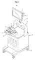
- FIG. 1 is a view showing an ultrasonic diagnostic apparatus in accordance with one embodiment of the present invention.
- the ultrasonic diagnostic apparatus 100 includes a main body 30, a probe 40 configured to transmit ultrasonic signals to an object to be diagnosed and to receive the signals reflected from the object, a main display 10 disposed above the main body 30 to display images of diagnostic results based on the received ultrasonic signals, and a control panel 50 to allow a user to operate the ultrasonic diagnostic apparatus 100.
- An auxiliary display 52 may be provided on one side of the control panel 50.
- Wheels 31 for movement of the ultrasonic diagnostic apparatus 100 may be mounted at the bottom of the main body 30.
- the control panel 50 and the display 10 are horizontally movable by movement of the main body 30.
- a grip portion 51 may protrude forward from the control panel 50.
- the user may grip the grip portion 51 to horizontally move the ultrasonic diagnostic apparatus 100 including the control panel 50.
- the user may move the control panel 50 vertically or horizontally by applying force to the grip portion 51 in a given direction.
- the grip portion 51 may be provided with a switch (not shown), and in this case, the user may automatically control movement of the ultrasonic diagnostic apparatus 100.
- the control panel 50 serves as an input unit to input data to the main body 30.
- the display 10 serves as an output unit to output data transmitted from the main body 30.
- the auxiliary display 52 provided on the control panel 50 also serves as the output unit.
- the control panel 50, the display 10, and the auxiliary display 52 are referred to as an input/output unit 70.
- control panel 50 will hereinafter be described by way of example, the following description is not limited thereto and the embodiment of the present invention may be applied to other elements coupled to the main body 30 of the ultrasonic diagnostic apparatus 100.
- the ultrasonic diagnostic apparatus 100 may further include a connection unit 60 to adjust a position of the input/output unit 70, more particularly, the control panel 50 and the display 10, based on shape of the user or use environment of the ultrasonic diagnostic apparatus 100. This will be described below.
- a connection unit 20 may be located between the display 10 and the main body 30 to couple the display 10 and the main body 30 to each other.
- the connection unit 20 may include a connection member 21 coupled to the display 10 and a support member 22 coupled to the main body 30. Through provision of the support member 22, a space is defined between the display 10 and the main body 30, which enables reception of elements required for ultrasonic diagnosis.
- FIG. 2 is a view schematically showing the structure of the connection unit in accordance with one embodiment of the present invention
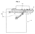
- FIG. 3 is a view showing a coupled state of the control panel and the main body in accordance with one embodiment of the present invention
- FIG. 4 is a view showing the coupled state of the control panel and the main body in accordance with one embodiment of the present invention when viewed at a different angle from FIG. 3 .
- connection unit 60 includes a plurality of connection members 61, 62, 65.
- Each of the connection members 61, 62, 65 is connected at one end thereof to the main body 30 and at the other end thereof to at least a portion of the input/output unit, more particularly, the control panel 50, to move the control panel 50 relative to the main body 30.
- a variable length connection member is referred to as a first connection member 65
- a load support connection member is referred to as a second connection member 61; 62.
- the second connection member 61; 62 may also have a variable length.
- a plurality of second connection members 61, 62 may be provided, and at least one first connection member 65 may be provided. As exemplarily shown in the drawings, two second connection members 61, 62 and one first connection member 65 may be provided, although the disclosure is not limited thereto.
- the second connection members 61, 62 and the first connection member 65 may be coupled to come into contact with one another at a point.
- the control panel 50 is mounted at a point where the second connection members 61, 62 and the first connection member 65 come into contact with one another.
- the second connection members 61, 62 may include second main body coupling parts 61 a, 62a coupled to the main body 30, and second input/output unit coupling parts 61 b, 62b coupled to the input/output unit.
- the first connection member 65 may include a first main body coupling part 65a coupled to the main body 30, and a first input/output unit coupling part 65b coupled to the input/output unit. That is, the second input/output unit coupling parts 61 b, 62b and the first input/output unit coupling part 65b may come into contact with one another at a point.
- the second main body coupling parts 61 a, 62a, the second input/output coupling parts 61 b, 62b, the first main body coupling part 65a, and the first input/output unit coupling part 65b, which are coupled to the main body 30 or the input/output unit 50; 10, may be at least one of ball joints or universal joints.
- a plane in which the second main body coupling parts 61 a, 62a and the first main body coupling part 65a are located on the main body 30 is referred to as a first plane
- a plane in which the second input/output unit coupling parts 61 b, 62b and the first input/output coupling part 65b are located on the control panel 50 is referred to as a second plane.
- the first plane and the second plane are different planes, and thus the connection unit 60 may have a 3-dimensional arrangement in a plurality of planes.
- connection unit 60 achieves a triangular pyramidal structure of coupling the main body 30 and the control panel 50 to each other. Movement of the control panel 50 will be described below.
- the ultrasonic diagnostic apparatus 100 includes the input/output unit 70 to input data to the main body 30 or to output data transmitted from the main body 30, and the connection unit 60 to couple the input/output unit 70 and the main body 30 to each other.
- a controller (not shown) may be provided to control movement of the connection unit 60 in response to user operation detected by the input/output unit 70.
- the controller (not shown) may be mounted in the main body 30.
- connection unit 60 may be manually moved by force applied to the input/output unit 70 by the user.
- the input/output unit 70 may detect variation of pressure applied by the user or variation of a user contact position and transmit the detected result to the controller (not shown).
- connection unit 60 may be automatically moved via user operation.
- connection unit 60 may initiate or stop movement in response to a control signal of the controller (not shown).
- both the first connection member 65 and the second connection members 61, 62 are length variable.
- FIG. 5 is a view showing upward or downward movement of the control panel in accordance with another embodiment of the present invention.
- the user may move the control panel 50 upward or downward.
- the length of the second connection members 61, 62 is increased and the length of the first connection member 65 is reduced, causing downward movement of the control panel 50.
- FIG. 6 is a view showing forward or rearward movement of the control panel in accordance with another embodiment of the present invention.
- the user may move the control panel 50 forward or rearward.
- the length of the two second connection members 61, 62 is increased and the length of one first connection member 65 is increased, causing forward movement of the control panel 50.
- FIG. 7 is a view showing leftward or rightward movement of the control panel in accordance with another embodiment of the present invention
- FIG. 8 is a view showing leftward or rightward movement of the control panel in accordance with another embodiment of the present invention when viewed at a different angle from FIG. 7 .
- the user may move the control panel 50 leftward or rightward relative to the main body 30.
- the length of the left second connection member 61 among the two second connection members 61, 62 is reduced and the length of the right second connection member 62 is increased.
- the length of the first connection member 65 is also increased. Thereby, the first connection member 65 is moved leftward, causing leftward movement of the control panel 50.
- the length of the right second connection member 62 among the two second connection members 61, 62 is reduced and the length of the left second connection member 61 is increased.
- the length of the first connection member 65 is also increased. Thereby, the first connection member 65 is moved rightward, causing rightward movement of the control panel 50.
- connection unit 60 since the respective connection members 61, 62, 65 are arranged to share a plurality of planes to realize a 3-dimensional structure of the connection unit 60, more effective distribution of load applied to the respective connection members 61, 62, 65 may be accomplished than in conventional configurations. In this way, the single connection unit 60 may serve to support the input/output unit 70 having great load. In addition, effective fixing of the input/output unit 70 may be accomplished owing to excellent fastening strength.
- FIGS. 9 and 10 are views schematically showing the structure of a connection unit in accordance with other embodiments of the present invention.
- a connection unit 160 may have a quadrangular pyramid shape.
- first connection members 161, 162 and two second connection members 163, 165 may be provided, but the present embodiment is not limited thereto, and two first connection members and one second connection member may be provided.
- a connection unit 160' may have a modified tetrahedral shape.
- the connection unit 160' may include a first connection member 163'and second connection members 161', 162'.
- connection unit 160' may further include a vertically movable third connection member 164'.
- the length of the first connection member 163' is variable as the third connection member 164' is vertically moved, causing movement of an input/output unit (not shown) coupled to an apex.
- connection members 161, 162, 163, 165; 161', 162', 163', 164' than those of the embodiments as exemplarily shown in FIGS. 1 to 8 thus achieving wider load distribution. This may realize more efficient support for an input/output unit having a great load.
- FIG. 11 is a view schematically showing the structure of a connection unit for the display in accordance with a further embodiment of the present invention.
- connection unit 170 may be located between the display 10 and a main body (not shown).
- the connection unit 170 may have a conical shape.
- Three connection members 171, 172, 173 may be provided as exemplarily shown in the drawing, but the embodiment is not limited thereto.
- connection members may include an input/output unit coupling part 175 coupled to the display 10, and main body coupling parts 171 a, 172a, 173a coupled to the main body (not shown).
- the input/output coupling part 175 corresponds to an apex of a cone.
- a disc-shaped base 174 may be additionally coupled to the connection members 171, 172, 173.
- the input/output unit 70 including the display 10 may be rotated via rotation of the base 174.
- the display 10 may be vertically or horizontally moved via variation in the length of the connection members 171, 172, 173.
- an ultrasonic diagnostic apparatus in accordance with the embodiment of the present invention provides a connection unit to simultaneously implement vertical movement and rotation.
- the connection unit includes a plurality of connection members to support load of an input/output unit, which realizes load distribution and support of a greater load.
- a simplified coupling configuration of the connection unit may ensure easy movement of the input/output unit.
Landscapes
- Engineering & Computer Science (AREA)
- Health & Medical Sciences (AREA)
- Life Sciences & Earth Sciences (AREA)
- General Engineering & Computer Science (AREA)
- Physics & Mathematics (AREA)
- Surgery (AREA)
- General Health & Medical Sciences (AREA)
- Pathology (AREA)
- Biomedical Technology (AREA)
- Heart & Thoracic Surgery (AREA)
- Medical Informatics (AREA)
- Molecular Biology (AREA)
- Nuclear Medicine, Radiotherapy & Molecular Imaging (AREA)
- Animal Behavior & Ethology (AREA)
- Radiology & Medical Imaging (AREA)
- Public Health (AREA)
- Veterinary Medicine (AREA)
- Biophysics (AREA)
- Mechanical Engineering (AREA)
- Human Computer Interaction (AREA)
- Computer Networks & Wireless Communication (AREA)
- General Physics & Mathematics (AREA)
- Radar, Positioning & Navigation (AREA)
- Remote Sensing (AREA)
- Ultra Sonic Daignosis Equipment (AREA)
Abstract
Description
- Embodiments of the present invention relate to an ultrasonic diagnostic apparatus having an improved configuration of a connection unit to change a position of an input/output unit.
- Generally, an ultrasonic diagnostic apparatus is designed to emit ultrasonic waves from the surface of the body of an object toward a region in the body to be diagnosed and to acquire tomograms of soft tissues or images of blood stream.
- A typical ultrasonic diagnostic apparatus includes a main body, a probe configured to transmit ultrasonic signals to an object and to receive signals reflected from the object, a display unit disposed above the main body to display images of diagnostic results based on the received ultrasonic signals, and a control panel disposed in front of the display unit to allow a user to operate the ultrasonic diagnostic apparatus.
- In the above described ultrasonic diagnostic apparatus, the control panel and the display unit are adjustable in height and position based on shape of the user and use environment.
- Conventionally, since vertical movement and rotation of an input/output unit such as the control panel and the display unit have been realized respectively via separate mechanisms therefor, a great number of elements may be necessary, causing problems upon production.
- It is an aspect of the present invention to provide an ultrasonic diagnostic apparatus having an improved configuration of a connection unit to enable simultaneous implementation of vertical movement, horizontal movement, and rotation of an input/output unit.
- Additional aspects of the invention will be set forth in part in the description which follows and, in part, will be obvious from the description, or may be learned by practice of the invention.
- In accordance with one aspect of the invention, an ultrasonic diagnostic apparatus includes a main body, at least one input/output unit coupled to one side of the main body to input data to the main body or to output data transmitted from the main body, and a connection unit to connect the input/output unit and the main body to each other, wherein the connection unit includes a plurality of first connection members, each of which is connected at one end thereof to the main body and at the other end thereof to at least a portion of the input/output unit and has a variable length to move the input/output unit relative to the main body, and at least one second connection member coupled to the first connection members and at least one of the main body or the input/output unit so as to come into contact with the same at a point to support load of the input/output unit.
- Each of the first connection members may include a first main body coupling part coupled to the main body and a first input/output unit coupling part coupled to the input/output unit, the second connection member may include a second main body coupling part coupled to the main body and a second input/output unit coupling part coupled to the input/output unit, the first main body coupling part and the second main body coupling part may be arranged in a first plane, and the first input/output coupling part and the second input/output coupling part may be arranged in a second plane.
- The first plane and the second plane may be different planes.
- Two first connection members and one second connection member may be arranged to provide the connection unit with a triangular pyramid shape.
- Two first connection members and two second connection members may be arranged to provide the connection unit with a quadrangular pyramid shape.
- The first plane may be at least one of a circular plane or an oval plane.
- The first main body coupling part, the first input/output unit coupling part, the second main body coupling part, and the second input/output coupling part may be at least one of ball joints and universal joints.
- The connection unit may be manually movable.
- The connection unit may be automatically movable.
- The at least one input unit may include a control panel to input a signal to the main body.
- The at least one input unit may include a display to output a signal generated in the main body.
- In accordance with another aspect of the invention, an ultrasonic diagnostic apparatus includes a main body, at least one input/output unit coupled to one side of the main body to input data to the main body or to output data transmitted from the main body, and a connection unit to connect the input/output unit and the main body to each other, the length of at least a portion of the connection unit being variable to allow the connection unit to move relative to the main body, wherein the connection unit is coupled at a plurality of points to at least one of the main body and the input unit to enable load distribution.
- The connection unit may include a plurality of first connection members having a variable length, and at least one second connection member coupled to the first connection members and at least one of the main body or the input/output unit so as to come into contact with the same at a point.
- Each of the first connection members may include a first main body coupling part coupled to the main body and a first input/output unit coupling part coupled to the input/output unit, the second connection member may include a second main body coupling part coupled to the main body and a second input/output unit coupling part coupled to the input/output unit, and the first input/output coupling part and the second input/output coupling part may come into contact with each other at a point.
- The first main body coupling part and the second main body coupling part may be arranged in a first plane, and the first input/output coupling part and the second input/output coupling part may be arranged in a second plane, and the first plane and the second plane may be different planes.
- Two first connection members and one second connection member may be arranged to provide the connection unit with a triangular pyramid shape.
- Two first connection members and two second connection members may be arranged to provide the connection unit with a quadrangular pyramid shape.
- The first plane may be at least one of a circular plane or an oval plane.
- These and/or other aspects of the invention will become apparent and more readily appreciated from the following description of the embodiments, taken in conjunction with the accompanying drawings of which:
-
FIG. 1 is a view showing an ultrasonic diagnostic apparatus in accordance with one embodiment of the present invention; -
FIG. 2 is a view schematically showing the structure of a connection unit in accordance with one embodiment of the present invention; -
FIG. 3 is a view showing a coupled state of a control panel and a main body in accordance with one embodiment of the present invention; -
FIG. 4 is a view showing the coupled state of the control panel and the main body in accordance with one embodiment of the present invention when viewed at a different angle fromFIG. 3 ; -
FIG. 5 is a view showing upward or downward movement of the control panel in accordance with another embodiment of the present invention; -
FIG. 6 is a view showing forward or rearward movement of the control panel in accordance with another embodiment of the present invention; -
FIG. 7 is a view showing leftward or rightward movement of the control panel in accordance with another embodiment of the present invention; -
FIG. 8 is a view showing leftward or rightward movement of the control panel in accordance with another embodiment of the present invention when viewed at a different angle fromFIG. 7 ; -
FIG. 9 is a view schematically showing the structure of a connection unit in accordance with another embodiment of the present invention; -
FIG. 10 is a view schematically showing the structure of a connection unit in accordance with another embodiment of the present invention; and -
FIG. 11 is a view schematically showing the structure of a connection unit for a display in accordance with a further embodiment of the present invention. - Reference will now be made in detail to the embodiments of the present invention, examples of which are illustrated in the accompanying drawings, wherein like reference numerals refer to like elements throughout.
-
FIG. 1 is a view showing an ultrasonic diagnostic apparatus in accordance with one embodiment of the present invention. - As exemplarily shown in
FIG. 1 , the ultrasonicdiagnostic apparatus 100 includes amain body 30, aprobe 40 configured to transmit ultrasonic signals to an object to be diagnosed and to receive the signals reflected from the object, amain display 10 disposed above themain body 30 to display images of diagnostic results based on the received ultrasonic signals, and acontrol panel 50 to allow a user to operate the ultrasonicdiagnostic apparatus 100. Anauxiliary display 52 may be provided on one side of thecontrol panel 50. -
Wheels 31 for movement of the ultrasonicdiagnostic apparatus 100 may be mounted at the bottom of themain body 30. Thecontrol panel 50 and thedisplay 10 are horizontally movable by movement of themain body 30. - A
grip portion 51 may protrude forward from thecontrol panel 50. The user may grip thegrip portion 51 to horizontally move the ultrasonicdiagnostic apparatus 100 including thecontrol panel 50. In addition, the user may move thecontrol panel 50 vertically or horizontally by applying force to thegrip portion 51 in a given direction. Thegrip portion 51 may be provided with a switch (not shown), and in this case, the user may automatically control movement of the ultrasonicdiagnostic apparatus 100. - The
control panel 50 serves as an input unit to input data to themain body 30. Thedisplay 10 serves as an output unit to output data transmitted from themain body 30. In one embodiment of the present invention, theauxiliary display 52 provided on thecontrol panel 50 also serves as the output unit. Thecontrol panel 50, thedisplay 10, and theauxiliary display 52 are referred to as an input/output unit 70. - Although the
control panel 50 will hereinafter be described by way of example, the following description is not limited thereto and the embodiment of the present invention may be applied to other elements coupled to themain body 30 of the ultrasonicdiagnostic apparatus 100. - The ultrasonic
diagnostic apparatus 100 may further include aconnection unit 60 to adjust a position of the input/output unit 70, more particularly, thecontrol panel 50 and thedisplay 10, based on shape of the user or use environment of the ultrasonicdiagnostic apparatus 100. This will be described below. - In one embodiment, a
connection unit 20 may be located between thedisplay 10 and themain body 30 to couple thedisplay 10 and themain body 30 to each other. Theconnection unit 20 may include aconnection member 21 coupled to thedisplay 10 and asupport member 22 coupled to themain body 30. Through provision of thesupport member 22, a space is defined between thedisplay 10 and themain body 30, which enables reception of elements required for ultrasonic diagnosis. -
FIG. 2 is a view schematically showing the structure of the connection unit in accordance with one embodiment of the present invention,FIG. 3 is a view showing a coupled state of the control panel and the main body in accordance with one embodiment of the present invention, andFIG. 4 is a view showing the coupled state of the control panel and the main body in accordance with one embodiment of the present invention when viewed at a different angle fromFIG. 3 . - As exemplarily shown in
FIGS. 2 to 4 , themain body 30 and thecontrol panel 50 are coupled to each other via theconnection unit 60. Theconnection unit 60 includes a plurality ofconnection members connection members main body 30 and at the other end thereof to at least a portion of the input/output unit, more particularly, thecontrol panel 50, to move thecontrol panel 50 relative to themain body 30. A variable length connection member is referred to as afirst connection member 65, and a load support connection member is referred to as asecond connection member 61; 62. In one embodiment of the present invention, thesecond connection member 61; 62 may also have a variable length. - A plurality of
second connection members first connection member 65 may be provided. As exemplarily shown in the drawings, twosecond connection members first connection member 65 may be provided, although the disclosure is not limited thereto. - The
second connection members first connection member 65 may be coupled to come into contact with one another at a point. As exemplarily shown in the drawings, thecontrol panel 50 is mounted at a point where thesecond connection members first connection member 65 come into contact with one another. Thesecond connection members body coupling parts main body 30, and second input/outputunit coupling parts 61 b, 62b coupled to the input/output unit. Thefirst connection member 65 may include a first mainbody coupling part 65a coupled to themain body 30, and a first input/outputunit coupling part 65b coupled to the input/output unit. That is, the second input/outputunit coupling parts 61 b, 62b and the first input/outputunit coupling part 65b may come into contact with one another at a point. - The second main
body coupling parts output coupling parts 61 b, 62b, the first mainbody coupling part 65a, and the first input/outputunit coupling part 65b, which are coupled to themain body 30 or the input/output unit 50; 10, may be at least one of ball joints or universal joints. - A plane in which the second main
body coupling parts body coupling part 65a are located on themain body 30 is referred to as a first plane, and a plane in which the second input/outputunit coupling parts 61 b, 62b and the first input/output coupling part 65b are located on thecontrol panel 50 is referred to as a second plane. The first plane and the second plane are different planes, and thus theconnection unit 60 may have a 3-dimensional arrangement in a plurality of planes. - In one embodiment of the present invention, two
second connection members first connection member 65 may be provided such that a total of threeconnection members control panel 50 to thereby be coupled to themain body 30. As such, theconnection unit 60 achieves a triangular pyramidal structure of coupling themain body 30 and thecontrol panel 50 to each other. Movement of thecontrol panel 50 will be described below. - The ultrasonic
diagnostic apparatus 100 includes the input/output unit 70 to input data to themain body 30 or to output data transmitted from themain body 30, and theconnection unit 60 to couple the input/output unit 70 and themain body 30 to each other. In addition, a controller (not shown) may be provided to control movement of theconnection unit 60 in response to user operation detected by the input/output unit 70. The controller (not shown) may be mounted in themain body 30. - The
connection unit 60 may be manually moved by force applied to the input/output unit 70 by the user. In this case, the input/output unit 70 may detect variation of pressure applied by the user or variation of a user contact position and transmit the detected result to the controller (not shown). - Of course, the disclosure is not limited to the above description, and the
connection unit 60 may be automatically moved via user operation. In this case, theconnection unit 60 may initiate or stop movement in response to a control signal of the controller (not shown). - Movement of the
control panel 50 will hereinafter be described with reference toFIGS. 5 to 8 . In the embodiment as exemplarily shown inFIGS. 5 to 8 , both thefirst connection member 65 and thesecond connection members -
FIG. 5 is a view showing upward or downward movement of the control panel in accordance with another embodiment of the present invention. - As exemplarily shown in
FIG. 5 , the user may move thecontrol panel 50 upward or downward. When attempting to move thecontrol panel 50 downward, the length of thesecond connection members first connection member 65 is reduced, causing downward movement of thecontrol panel 50. - When attempting to move the
control panel 50 upward, contrary to the above described downward movement, the length of thesecond connection members control panel 50. -
FIG. 6 is a view showing forward or rearward movement of the control panel in accordance with another embodiment of the present invention. - As exemplarily shown in
FIG. 6 , the user may move thecontrol panel 50 forward or rearward. When attempting to move thecontrol panel 50 forward, the length of the twosecond connection members first connection member 65 is increased, causing forward movement of thecontrol panel 50. - When attempting to move the
control panel 50 rearward, i.e. to move the forwardly movedcontrol panel 50 toward themain body 30, the length of the twosecond connection members control panel 50 to move toward themain body 30. -
FIG. 7 is a view showing leftward or rightward movement of the control panel in accordance with another embodiment of the present invention, andFIG. 8 is a view showing leftward or rightward movement of the control panel in accordance with another embodiment of the present invention when viewed at a different angle fromFIG. 7 . - As exemplarily shown in
FIGS. 7 and8 , the user may move thecontrol panel 50 leftward or rightward relative to themain body 30. - When attempting to move the
control panel 50 leftward relative to themain body 30, the length of the leftsecond connection member 61 among the twosecond connection members second connection member 62 is increased. The length of thefirst connection member 65 is also increased. Thereby, thefirst connection member 65 is moved leftward, causing leftward movement of thecontrol panel 50. - When attempting to move the
control panel 50 rightward relative to themain body 30, the length of the rightsecond connection member 62 among the twosecond connection members second connection member 61 is increased. The length of thefirst connection member 65 is also increased. Thereby, thefirst connection member 65 is moved rightward, causing rightward movement of thecontrol panel 50. - In one embodiment of the present invention, since the
respective connection members connection unit 60, more effective distribution of load applied to therespective connection members single connection unit 60 may serve to support the input/output unit 70 having great load. In addition, effective fixing of the input/output unit 70 may be accomplished owing to excellent fastening strength. -
FIGS. 9 and10 are views schematically showing the structure of a connection unit in accordance with other embodiments of the present invention. - As exemplarily shown in
FIG. 9 , aconnection unit 160 may have a quadrangular pyramid shape. - As exemplarily shown in the drawing, two
first connection members second connection members - As exemplarily shown in
FIG. 10 , a connection unit 160' may have a modified tetrahedral shape. In this case, the connection unit 160' may include a first connection member 163'and second connection members 161', 162'. - In one embodiment of the present invention as exemplarily shown in
FIG. 10 , the connection unit 160' may further include a vertically movable third connection member 164'. The length of the first connection member 163' is variable as the third connection member 164' is vertically moved, causing movement of an input/output unit (not shown) coupled to an apex. - The embodiments of the present invention as exemplarily shown in
FIGS. 9 and10 employ a greater number ofconnection members FIGS. 1 to 8 , thus achieving wider load distribution. This may realize more efficient support for an input/output unit having a great load. -
FIG. 11 is a view schematically showing the structure of a connection unit for the display in accordance with a further embodiment of the present invention. - As exemplarily shown in
FIG. 11 , aconnection unit 170 may be located between thedisplay 10 and a main body (not shown). In one embodiment of the present invention, theconnection unit 170 may have a conical shape. Threeconnection members - The respective connection members may include an input/output
unit coupling part 175 coupled to thedisplay 10, and mainbody coupling parts output coupling part 175 corresponds to an apex of a cone. - In the case of the
conical connection unit 170, a disc-shapedbase 174 may be additionally coupled to theconnection members display 10 may be rotated via rotation of thebase 174. In addition, thedisplay 10 may be vertically or horizontally moved via variation in the length of theconnection members - As is apparent from the above description, an ultrasonic diagnostic apparatus in accordance with the embodiment of the present invention provides a connection unit to simultaneously implement vertical movement and rotation. Further, the connection unit includes a plurality of connection members to support load of an input/output unit, which realizes load distribution and support of a greater load. Furthermore, a simplified coupling configuration of the connection unit may ensure easy movement of the input/output unit.
- Although the embodiments of the present invention have been shown and described, it would be appreciated by those skilled in the art that changes may be made in these embodiments without departing from the principles and spirit of the invention, the scope of which is defined in the claims and their equivalents.
Claims (11)
- An ultrasonic diagnostic apparatus comprising:a main body;at least one input/output unit coupled to one side of the main body to input data to the main body or to output data transmitted from the main body; anda connection unit to connect the input/output unit and the main body to each other,wherein the connection unit includes:a plurality of first connection members, each of which is connected at one end thereof to the main body and at the other end thereof to at least a portion of the input/output unit and has a variable length to move the input/output unit relative to the main body; andat least one second connection member coupled to the first connection members and at least one of the main body or the input/output unit so as to come into contact with the same at a point to support load of the input/output unit.
- The apparatus according to claim 1, wherein each of the first connection members includes a first main body coupling part coupled to the main body and a first input/output unit coupling part coupled to the input/output unit,
wherein the second connection member includes a second main body coupling part coupled to the main body and a second input/output unit coupling part coupled to the input/output unit,
wherein the first main body coupling part and the second main body coupling part are arranged in a first plane, and
wherein the first input/output coupling part and the second input/output coupling part are arranged in a second plane. - The apparatus according to claim 2, wherein the first plane and the second plane are different planes.
- The apparatus according to claim 3, wherein two first connection members and one second connection member are arranged to provide the connection unit with a triangular pyramid shape.
- The apparatus according to claim 3, wherein two first connection members and two second connection members are arranged to provide the connection unit with a quadrangular pyramid shape.
- The apparatus according to claim 3, wherein the first plane is at least one of a circular plane or an oval plane.
- The apparatus according to claim 2, wherein the first main body coupling part, the first input/output unit coupling part, the second main body coupling part, and the second input/output coupling part are at least one of ball joints and universal joints.
- The apparatus according to claim 1, wherein the connection unit is manually movable.
- The apparatus according to claim 1, wherein the connection unit is automatically movable.
- The apparatus according to claim 1, wherein the at least one input unit includes a control panel to input a signal to the main body.
- The apparatus according to claim 1, wherein the at least one input unit includes a display to output a signal generated in the main body.
Applications Claiming Priority (1)
| Application Number | Priority Date | Filing Date | Title |
|---|---|---|---|
| KR1020130094515A KR102135149B1 (en) | 2013-08-09 | 2013-08-09 | Ultrasonic Diagnostic Apparatus |
Publications (2)
| Publication Number | Publication Date |
|---|---|
| EP2845542A1 true EP2845542A1 (en) | 2015-03-11 |
| EP2845542B1 EP2845542B1 (en) | 2020-04-29 |
Family
ID=51211509
Family Applications (1)
| Application Number | Title | Priority Date | Filing Date |
|---|---|---|---|
| EP14173456.6A Active EP2845542B1 (en) | 2013-08-09 | 2014-06-23 | Ultrasonic diagnostic apparatus |
Country Status (3)
| Country | Link |
|---|---|
| US (1) | US9861339B2 (en) |
| EP (1) | EP2845542B1 (en) |
| KR (1) | KR102135149B1 (en) |
Families Citing this family (4)
| Publication number | Priority date | Publication date | Assignee | Title |
|---|---|---|---|---|
| KR102135149B1 (en) * | 2013-08-09 | 2020-07-17 | 삼성메디슨 주식회사 | Ultrasonic Diagnostic Apparatus |
| CN111358490A (en) * | 2015-11-16 | 2020-07-03 | 深圳迈瑞生物医疗电子股份有限公司 | Floating mechanism and ultrasonic diagnostic apparatus thereof |
| CN110113999B (en) * | 2017-05-15 | 2022-05-27 | 深圳迈瑞生物医疗电子股份有限公司 | Floating mechanism and ultrasonic diagnostic apparatus |
| CN114352860B (en) * | 2021-12-07 | 2024-03-19 | 北京无线电计量测试研究所 | A probe support device |
Citations (3)
| Publication number | Priority date | Publication date | Assignee | Title |
|---|---|---|---|---|
| WO2005074807A1 (en) * | 2004-02-06 | 2005-08-18 | Koninklijke Philips Electronics N.V. | Diagnostic ultrasound system with grippable articulating flat panel display |
| EP2092892A1 (en) * | 2006-11-27 | 2009-08-26 | Hitachi Medical Corporation | Ultrasonograph |
| US20120182709A1 (en) * | 2011-01-19 | 2012-07-19 | Akimasa Asai | Support arm and image display device |
Family Cites Families (7)
| Publication number | Priority date | Publication date | Assignee | Title |
|---|---|---|---|---|
| US20040068185A1 (en) * | 2002-10-08 | 2004-04-08 | Marshall Elizabeth A. | Ultrasonic diagnostic imaging system with articulating display handle |
| JP4272077B2 (en) * | 2004-01-20 | 2009-06-03 | 株式会社島津製作所 | Ultrasonic probe fixing apparatus and ultrasonic diagnostic apparatus using the apparatus |
| JP4381340B2 (en) * | 2005-04-11 | 2009-12-09 | ジーイー・メディカル・システムズ・グローバル・テクノロジー・カンパニー・エルエルシー | Ultrasonic diagnostic equipment |
| US20070010745A1 (en) * | 2005-06-16 | 2007-01-11 | Siemens Medical Solutions Usa, Inc. | Mechanism for ergonomic positioning of a control panel for a diagnostic ultrasound system |
| US9180898B2 (en) * | 2011-09-30 | 2015-11-10 | Hitachi Aloka Medical, Ltd. | Cart for portable ultrasonic diagnostic device and ultrasonic diagnostic unit |
| EP2832296A4 (en) * | 2012-03-28 | 2015-12-09 | Hitachi Aloka Medical Ltd | PORTABLE ULTRASONIC DIAGNOSTIC DEVICE |
| KR102135149B1 (en) * | 2013-08-09 | 2020-07-17 | 삼성메디슨 주식회사 | Ultrasonic Diagnostic Apparatus |
-
2013
- 2013-08-09 KR KR1020130094515A patent/KR102135149B1/en active Active
-
2014
- 2014-06-23 EP EP14173456.6A patent/EP2845542B1/en active Active
- 2014-08-08 US US14/455,400 patent/US9861339B2/en active Active
Patent Citations (3)
| Publication number | Priority date | Publication date | Assignee | Title |
|---|---|---|---|---|
| WO2005074807A1 (en) * | 2004-02-06 | 2005-08-18 | Koninklijke Philips Electronics N.V. | Diagnostic ultrasound system with grippable articulating flat panel display |
| EP2092892A1 (en) * | 2006-11-27 | 2009-08-26 | Hitachi Medical Corporation | Ultrasonograph |
| US20120182709A1 (en) * | 2011-01-19 | 2012-07-19 | Akimasa Asai | Support arm and image display device |
Also Published As
| Publication number | Publication date |
|---|---|
| US20150045672A1 (en) | 2015-02-12 |
| KR20150018068A (en) | 2015-02-23 |
| EP2845542B1 (en) | 2020-04-29 |
| US9861339B2 (en) | 2018-01-09 |
| KR102135149B1 (en) | 2020-07-17 |
Similar Documents
| Publication | Publication Date | Title |
|---|---|---|
| US9861339B2 (en) | Ultrasonic diagnostic apparatus | |
| US11419582B2 (en) | Ultrasound imaging system with a multi-mode touch screen interface | |
| CN106999149B (en) | Multi-sensor ultrasound probe and related methods | |
| EP2023820B1 (en) | Biopsy system with integrated ultrasonic imaging | |
| US11432796B2 (en) | Positioning support and fetal heart rate registration support for CTG ultrasound transducers | |
| EP2510880A1 (en) | Ultrasound diagnostic system | |
| JP2008536603A (en) | Ultrasonic diagnostic imaging system set by probe firmware | |
| US12121397B2 (en) | Systems and methods for passive wire management | |
| CN108291963A (en) | Ultrasonic system with the microbeamformers for different transducer arrays | |
| JP2014520625A (en) | Ultrasonic image display probe | |
| US9017262B2 (en) | Systems and methods for connection to a transducer in ultrasound probes | |
| US20160206398A1 (en) | Medical imaging system with mechanical arm | |
| US20130303917A1 (en) | Ultrasound probe and ultrasound diagnosis apparatus | |
| JP6510290B2 (en) | Ultrasonic probe and ultrasonic diagnostic apparatus | |
| KR102709896B1 (en) | The Ultrasonic Diagnostic Apparatus And Control Method Thereof | |
| EP3053526B1 (en) | Ultrasonic diagnostic apparatus and control method thereof | |
| EP3771498B1 (en) | Ultrasound probe and ultrasound diagnosis apparatus | |
| JP5513826B2 (en) | Puncture adapter and ultrasonic diagnostic apparatus | |
| JP5566830B2 (en) | Ultrasonic diagnostic apparatus and probe connector | |
| KR20210125043A (en) | ultrasound imaging device | |
| KR102306139B1 (en) | Ultrasonic diagnostic apparatus and control method thereof | |
| JP6878037B2 (en) | Ultrasound diagnostic equipment and medical image processing equipment | |
| US20240341725A1 (en) | Ultrasonic imaging apparatus | |
| JP7501331B2 (en) | Ultrasound probe holder, ultrasound diagnostic device, cart for ultrasound diagnostic device, and ultrasound diagnostic system | |
| KR102584615B1 (en) | Intravascular ultrasound transducer for simultaneous implementation of multiple functions and image acquisition apparatus system using the same |
Legal Events
| Date | Code | Title | Description |
|---|---|---|---|
| 17P | Request for examination filed |
Effective date: 20140623 |
|
| AK | Designated contracting states |
Kind code of ref document: A1 Designated state(s): AL AT BE BG CH CY CZ DE DK EE ES FI FR GB GR HR HU IE IS IT LI LT LU LV MC MK MT NL NO PL PT RO RS SE SI SK SM TR |
|
| AX | Request for extension of the european patent |
Extension state: BA ME |
|
| PUAI | Public reference made under article 153(3) epc to a published international application that has entered the european phase |
Free format text: ORIGINAL CODE: 0009012 |
|
| R17P | Request for examination filed (corrected) |
Effective date: 20150911 |
|
| RBV | Designated contracting states (corrected) |
Designated state(s): AL AT BE BG CH CY CZ DE DK EE ES FI FR GB GR HR HU IE IS IT LI LT LU LV MC MK MT NL NO PL PT RO RS SE SI SK SM TR |
|
| STAA | Information on the status of an ep patent application or granted ep patent |
Free format text: STATUS: EXAMINATION IS IN PROGRESS |
|
| 17Q | First examination report despatched |
Effective date: 20170209 |
|
| GRAP | Despatch of communication of intention to grant a patent |
Free format text: ORIGINAL CODE: EPIDOSNIGR1 |
|
| STAA | Information on the status of an ep patent application or granted ep patent |
Free format text: STATUS: GRANT OF PATENT IS INTENDED |
|
| INTG | Intention to grant announced |
Effective date: 20200211 |
|
| GRAS | Grant fee paid |
Free format text: ORIGINAL CODE: EPIDOSNIGR3 |
|
| GRAA | (expected) grant |
Free format text: ORIGINAL CODE: 0009210 |
|
| STAA | Information on the status of an ep patent application or granted ep patent |
Free format text: STATUS: THE PATENT HAS BEEN GRANTED |
|
| AK | Designated contracting states |
Kind code of ref document: B1 Designated state(s): AL AT BE BG CH CY CZ DE DK EE ES FI FR GB GR HR HU IE IS IT LI LT LU LV MC MK MT NL NO PL PT RO RS SE SI SK SM TR |
|
| REG | Reference to a national code |
Ref country code: GB Ref legal event code: FG4D |
|
| REG | Reference to a national code |
Ref country code: CH Ref legal event code: EP |
|
| REG | Reference to a national code |
Ref country code: AT Ref legal event code: REF Ref document number: 1262126 Country of ref document: AT Kind code of ref document: T Effective date: 20200515 |
|
| REG | Reference to a national code |
Ref country code: DE Ref legal event code: R096 Ref document number: 602014064409 Country of ref document: DE |
|
| REG | Reference to a national code |
Ref country code: IE Ref legal event code: FG4D |
|
| REG | Reference to a national code |
Ref country code: NL Ref legal event code: MP Effective date: 20200429 |
|
| REG | Reference to a national code |
Ref country code: LT Ref legal event code: MG4D |
|
| PG25 | Lapsed in a contracting state [announced via postgrant information from national office to epo] |
Ref country code: NO Free format text: LAPSE BECAUSE OF FAILURE TO SUBMIT A TRANSLATION OF THE DESCRIPTION OR TO PAY THE FEE WITHIN THE PRESCRIBED TIME-LIMIT Effective date: 20200729 Ref country code: LT Free format text: LAPSE BECAUSE OF FAILURE TO SUBMIT A TRANSLATION OF THE DESCRIPTION OR TO PAY THE FEE WITHIN THE PRESCRIBED TIME-LIMIT Effective date: 20200429 Ref country code: FI Free format text: LAPSE BECAUSE OF FAILURE TO SUBMIT A TRANSLATION OF THE DESCRIPTION OR TO PAY THE FEE WITHIN THE PRESCRIBED TIME-LIMIT Effective date: 20200429 Ref country code: IS Free format text: LAPSE BECAUSE OF FAILURE TO SUBMIT A TRANSLATION OF THE DESCRIPTION OR TO PAY THE FEE WITHIN THE PRESCRIBED TIME-LIMIT Effective date: 20200829 Ref country code: SE Free format text: LAPSE BECAUSE OF FAILURE TO SUBMIT A TRANSLATION OF THE DESCRIPTION OR TO PAY THE FEE WITHIN THE PRESCRIBED TIME-LIMIT Effective date: 20200429 Ref country code: PT Free format text: LAPSE BECAUSE OF FAILURE TO SUBMIT A TRANSLATION OF THE DESCRIPTION OR TO PAY THE FEE WITHIN THE PRESCRIBED TIME-LIMIT Effective date: 20200831 Ref country code: GR Free format text: LAPSE BECAUSE OF FAILURE TO SUBMIT A TRANSLATION OF THE DESCRIPTION OR TO PAY THE FEE WITHIN THE PRESCRIBED TIME-LIMIT Effective date: 20200730 |
|
| REG | Reference to a national code |
Ref country code: AT Ref legal event code: MK05 Ref document number: 1262126 Country of ref document: AT Kind code of ref document: T Effective date: 20200429 |
|
| PG25 | Lapsed in a contracting state [announced via postgrant information from national office to epo] |
Ref country code: RS Free format text: LAPSE BECAUSE OF FAILURE TO SUBMIT A TRANSLATION OF THE DESCRIPTION OR TO PAY THE FEE WITHIN THE PRESCRIBED TIME-LIMIT Effective date: 20200429 Ref country code: LV Free format text: LAPSE BECAUSE OF FAILURE TO SUBMIT A TRANSLATION OF THE DESCRIPTION OR TO PAY THE FEE WITHIN THE PRESCRIBED TIME-LIMIT Effective date: 20200429 Ref country code: HR Free format text: LAPSE BECAUSE OF FAILURE TO SUBMIT A TRANSLATION OF THE DESCRIPTION OR TO PAY THE FEE WITHIN THE PRESCRIBED TIME-LIMIT Effective date: 20200429 Ref country code: BG Free format text: LAPSE BECAUSE OF FAILURE TO SUBMIT A TRANSLATION OF THE DESCRIPTION OR TO PAY THE FEE WITHIN THE PRESCRIBED TIME-LIMIT Effective date: 20200729 |
|
| PG25 | Lapsed in a contracting state [announced via postgrant information from national office to epo] |
Ref country code: AL Free format text: LAPSE BECAUSE OF FAILURE TO SUBMIT A TRANSLATION OF THE DESCRIPTION OR TO PAY THE FEE WITHIN THE PRESCRIBED TIME-LIMIT Effective date: 20200429 Ref country code: NL Free format text: LAPSE BECAUSE OF FAILURE TO SUBMIT A TRANSLATION OF THE DESCRIPTION OR TO PAY THE FEE WITHIN THE PRESCRIBED TIME-LIMIT Effective date: 20200429 |
|
| PG25 | Lapsed in a contracting state [announced via postgrant information from national office to epo] |
Ref country code: MC Free format text: LAPSE BECAUSE OF FAILURE TO SUBMIT A TRANSLATION OF THE DESCRIPTION OR TO PAY THE FEE WITHIN THE PRESCRIBED TIME-LIMIT Effective date: 20200429 Ref country code: ES Free format text: LAPSE BECAUSE OF FAILURE TO SUBMIT A TRANSLATION OF THE DESCRIPTION OR TO PAY THE FEE WITHIN THE PRESCRIBED TIME-LIMIT Effective date: 20200429 Ref country code: SM Free format text: LAPSE BECAUSE OF FAILURE TO SUBMIT A TRANSLATION OF THE DESCRIPTION OR TO PAY THE FEE WITHIN THE PRESCRIBED TIME-LIMIT Effective date: 20200429 Ref country code: DK Free format text: LAPSE BECAUSE OF FAILURE TO SUBMIT A TRANSLATION OF THE DESCRIPTION OR TO PAY THE FEE WITHIN THE PRESCRIBED TIME-LIMIT Effective date: 20200429 Ref country code: AT Free format text: LAPSE BECAUSE OF FAILURE TO SUBMIT A TRANSLATION OF THE DESCRIPTION OR TO PAY THE FEE WITHIN THE PRESCRIBED TIME-LIMIT Effective date: 20200429 Ref country code: CZ Free format text: LAPSE BECAUSE OF FAILURE TO SUBMIT A TRANSLATION OF THE DESCRIPTION OR TO PAY THE FEE WITHIN THE PRESCRIBED TIME-LIMIT Effective date: 20200429 Ref country code: RO Free format text: LAPSE BECAUSE OF FAILURE TO SUBMIT A TRANSLATION OF THE DESCRIPTION OR TO PAY THE FEE WITHIN THE PRESCRIBED TIME-LIMIT Effective date: 20200429 Ref country code: EE Free format text: LAPSE BECAUSE OF FAILURE TO SUBMIT A TRANSLATION OF THE DESCRIPTION OR TO PAY THE FEE WITHIN THE PRESCRIBED TIME-LIMIT Effective date: 20200429 |
|
| REG | Reference to a national code |
Ref country code: CH Ref legal event code: PL |
|
| REG | Reference to a national code |
Ref country code: DE Ref legal event code: R097 Ref document number: 602014064409 Country of ref document: DE |
|
| PG25 | Lapsed in a contracting state [announced via postgrant information from national office to epo] |
Ref country code: PL Free format text: LAPSE BECAUSE OF FAILURE TO SUBMIT A TRANSLATION OF THE DESCRIPTION OR TO PAY THE FEE WITHIN THE PRESCRIBED TIME-LIMIT Effective date: 20200429 Ref country code: SK Free format text: LAPSE BECAUSE OF FAILURE TO SUBMIT A TRANSLATION OF THE DESCRIPTION OR TO PAY THE FEE WITHIN THE PRESCRIBED TIME-LIMIT Effective date: 20200429 |
|
| PLBE | No opposition filed within time limit |
Free format text: ORIGINAL CODE: 0009261 |
|
| STAA | Information on the status of an ep patent application or granted ep patent |
Free format text: STATUS: NO OPPOSITION FILED WITHIN TIME LIMIT |
|
| GBPC | Gb: european patent ceased through non-payment of renewal fee |
Effective date: 20200729 |
|
| PG25 | Lapsed in a contracting state [announced via postgrant information from national office to epo] |
Ref country code: LU Free format text: LAPSE BECAUSE OF NON-PAYMENT OF DUE FEES Effective date: 20200623 |
|
| 26N | No opposition filed |
Effective date: 20210201 |
|
| REG | Reference to a national code |
Ref country code: BE Ref legal event code: MM Effective date: 20200630 |
|
| PG25 | Lapsed in a contracting state [announced via postgrant information from national office to epo] |
Ref country code: CH Free format text: LAPSE BECAUSE OF NON-PAYMENT OF DUE FEES Effective date: 20200630 Ref country code: GB Free format text: LAPSE BECAUSE OF NON-PAYMENT OF DUE FEES Effective date: 20200729 Ref country code: IE Free format text: LAPSE BECAUSE OF NON-PAYMENT OF DUE FEES Effective date: 20200623 Ref country code: LI Free format text: LAPSE BECAUSE OF NON-PAYMENT OF DUE FEES Effective date: 20200630 |
|
| PG25 | Lapsed in a contracting state [announced via postgrant information from national office to epo] |
Ref country code: BE Free format text: LAPSE BECAUSE OF NON-PAYMENT OF DUE FEES Effective date: 20200630 Ref country code: SI Free format text: LAPSE BECAUSE OF FAILURE TO SUBMIT A TRANSLATION OF THE DESCRIPTION OR TO PAY THE FEE WITHIN THE PRESCRIBED TIME-LIMIT Effective date: 20200429 |
|
| PG25 | Lapsed in a contracting state [announced via postgrant information from national office to epo] |
Ref country code: TR Free format text: LAPSE BECAUSE OF FAILURE TO SUBMIT A TRANSLATION OF THE DESCRIPTION OR TO PAY THE FEE WITHIN THE PRESCRIBED TIME-LIMIT Effective date: 20200429 Ref country code: MT Free format text: LAPSE BECAUSE OF FAILURE TO SUBMIT A TRANSLATION OF THE DESCRIPTION OR TO PAY THE FEE WITHIN THE PRESCRIBED TIME-LIMIT Effective date: 20200429 Ref country code: CY Free format text: LAPSE BECAUSE OF FAILURE TO SUBMIT A TRANSLATION OF THE DESCRIPTION OR TO PAY THE FEE WITHIN THE PRESCRIBED TIME-LIMIT Effective date: 20200429 |
|
| PG25 | Lapsed in a contracting state [announced via postgrant information from national office to epo] |
Ref country code: MK Free format text: LAPSE BECAUSE OF FAILURE TO SUBMIT A TRANSLATION OF THE DESCRIPTION OR TO PAY THE FEE WITHIN THE PRESCRIBED TIME-LIMIT Effective date: 20200429 |
|
| PGFP | Annual fee paid to national office [announced via postgrant information from national office to epo] |
Ref country code: DE Payment date: 20250508 Year of fee payment: 12 |
|
| PGFP | Annual fee paid to national office [announced via postgrant information from national office to epo] |
Ref country code: IT Payment date: 20250512 Year of fee payment: 12 |
|
| PGFP | Annual fee paid to national office [announced via postgrant information from national office to epo] |
Ref country code: FR Payment date: 20250513 Year of fee payment: 12 |