EP2844941B1 - Heat exchanger - Google Patents
Heat exchanger Download PDFInfo
- Publication number
- EP2844941B1 EP2844941B1 EP13809578.1A EP13809578A EP2844941B1 EP 2844941 B1 EP2844941 B1 EP 2844941B1 EP 13809578 A EP13809578 A EP 13809578A EP 2844941 B1 EP2844941 B1 EP 2844941B1
- Authority
- EP
- European Patent Office
- Prior art keywords
- heat exchanger
- housing
- casing
- flow guide
- water
- Prior art date
- Legal status (The legal status is an assumption and is not a legal conclusion. Google has not performed a legal analysis and makes no representation as to the accuracy of the status listed.)
- Not-in-force
Links
Images


Classifications
-
- F—MECHANICAL ENGINEERING; LIGHTING; HEATING; WEAPONS; BLASTING
- F28—HEAT EXCHANGE IN GENERAL
- F28D—HEAT-EXCHANGE APPARATUS, NOT PROVIDED FOR IN ANOTHER SUBCLASS, IN WHICH THE HEAT-EXCHANGE MEDIA DO NOT COME INTO DIRECT CONTACT
- F28D7/00—Heat-exchange apparatus having stationary tubular conduit assemblies for both heat-exchange media, the media being in contact with different sides of a conduit wall
- F28D7/02—Heat-exchange apparatus having stationary tubular conduit assemblies for both heat-exchange media, the media being in contact with different sides of a conduit wall the conduits being helically coiled
- F28D7/022—Heat-exchange apparatus having stationary tubular conduit assemblies for both heat-exchange media, the media being in contact with different sides of a conduit wall the conduits being helically coiled the conduits of two or more media in heat-exchange relationship being helically coiled, the coils having a cylindrical configuration
-
- F—MECHANICAL ENGINEERING; LIGHTING; HEATING; WEAPONS; BLASTING
- F28—HEAT EXCHANGE IN GENERAL
- F28F—DETAILS OF HEAT-EXCHANGE AND HEAT-TRANSFER APPARATUS, OF GENERAL APPLICATION
- F28F21/00—Constructions of heat-exchange apparatus characterised by the selection of particular materials
- F28F21/06—Constructions of heat-exchange apparatus characterised by the selection of particular materials of plastics material
-
- F—MECHANICAL ENGINEERING; LIGHTING; HEATING; WEAPONS; BLASTING
- F28—HEAT EXCHANGE IN GENERAL
- F28D—HEAT-EXCHANGE APPARATUS, NOT PROVIDED FOR IN ANOTHER SUBCLASS, IN WHICH THE HEAT-EXCHANGE MEDIA DO NOT COME INTO DIRECT CONTACT
- F28D7/00—Heat-exchange apparatus having stationary tubular conduit assemblies for both heat-exchange media, the media being in contact with different sides of a conduit wall
- F28D7/02—Heat-exchange apparatus having stationary tubular conduit assemblies for both heat-exchange media, the media being in contact with different sides of a conduit wall the conduits being helically coiled
- F28D7/024—Heat-exchange apparatus having stationary tubular conduit assemblies for both heat-exchange media, the media being in contact with different sides of a conduit wall the conduits being helically coiled the conduits of only one medium being helically coiled tubes, the coils having a cylindrical configuration
-
- F—MECHANICAL ENGINEERING; LIGHTING; HEATING; WEAPONS; BLASTING
- F28—HEAT EXCHANGE IN GENERAL
- F28D—HEAT-EXCHANGE APPARATUS, NOT PROVIDED FOR IN ANOTHER SUBCLASS, IN WHICH THE HEAT-EXCHANGE MEDIA DO NOT COME INTO DIRECT CONTACT
- F28D7/00—Heat-exchange apparatus having stationary tubular conduit assemblies for both heat-exchange media, the media being in contact with different sides of a conduit wall
- F28D7/10—Heat-exchange apparatus having stationary tubular conduit assemblies for both heat-exchange media, the media being in contact with different sides of a conduit wall the conduits being arranged one within the other, e.g. concentrically
- F28D7/106—Heat-exchange apparatus having stationary tubular conduit assemblies for both heat-exchange media, the media being in contact with different sides of a conduit wall the conduits being arranged one within the other, e.g. concentrically consisting of two coaxial conduits or modules of two coaxial conduits
-
- F—MECHANICAL ENGINEERING; LIGHTING; HEATING; WEAPONS; BLASTING
- F28—HEAT EXCHANGE IN GENERAL
- F28D—HEAT-EXCHANGE APPARATUS, NOT PROVIDED FOR IN ANOTHER SUBCLASS, IN WHICH THE HEAT-EXCHANGE MEDIA DO NOT COME INTO DIRECT CONTACT
- F28D7/00—Heat-exchange apparatus having stationary tubular conduit assemblies for both heat-exchange media, the media being in contact with different sides of a conduit wall
- F28D7/10—Heat-exchange apparatus having stationary tubular conduit assemblies for both heat-exchange media, the media being in contact with different sides of a conduit wall the conduits being arranged one within the other, e.g. concentrically
- F28D7/14—Heat-exchange apparatus having stationary tubular conduit assemblies for both heat-exchange media, the media being in contact with different sides of a conduit wall the conduits being arranged one within the other, e.g. concentrically both tubes being bent
-
- F—MECHANICAL ENGINEERING; LIGHTING; HEATING; WEAPONS; BLASTING
- F28—HEAT EXCHANGE IN GENERAL
- F28F—DETAILS OF HEAT-EXCHANGE AND HEAT-TRANSFER APPARATUS, OF GENERAL APPLICATION
- F28F9/00—Casings; Header boxes; Auxiliary supports for elements; Auxiliary members within casings
- F28F9/007—Auxiliary supports for elements
- F28F9/013—Auxiliary supports for elements for tubes or tube-assemblies
- F28F9/0132—Auxiliary supports for elements for tubes or tube-assemblies formed by slats, tie-rods, articulated or expandable rods
-
- F—MECHANICAL ENGINEERING; LIGHTING; HEATING; WEAPONS; BLASTING
- F28—HEAT EXCHANGE IN GENERAL
- F28F—DETAILS OF HEAT-EXCHANGE AND HEAT-TRANSFER APPARATUS, OF GENERAL APPLICATION
- F28F2275/00—Fastening; Joining
- F28F2275/08—Fastening; Joining by clamping or clipping
- F28F2275/085—Fastening; Joining by clamping or clipping with snap connection
-
- F—MECHANICAL ENGINEERING; LIGHTING; HEATING; WEAPONS; BLASTING
- F28—HEAT EXCHANGE IN GENERAL
- F28F—DETAILS OF HEAT-EXCHANGE AND HEAT-TRANSFER APPARATUS, OF GENERAL APPLICATION
- F28F2280/00—Mounting arrangements; Arrangements for facilitating assembling or disassembling of heat exchanger parts
Definitions
- the present invention relates to a heat exchanger.
- the present invention relates to a heat exchanger for heating water.
- the heat exchanger has particular application in the heating of swimming pools and spas, although it will be appreciated that it can be readily used in other applications across diverse industries.
- Heat exchangers are used to transfer heat from a heat source or thermal mass into a fluid mass, such as the water in a swimming pool or spa. Heat exchangers can be used for example to either raise or lower the temperature of a fluid, for various applications, such as heating or cooling, and heat exchangers are used in various industrial applications such as automotive, air conditioning, power generation and shipping among others.
- heat exchangers are suitable in a heating system for a swimming pool which uses a heat pump system to maintain a warm temperature of the pool.
- the heat pump extracts heat from surrounding air and transfers it to the body of water in the pool.
- Heat pump generally use less energy compared to gas or electric heaters to transfer heat to a body of water. Heat pumps transfer heat by circulating a substance called a refrigerant through a cycle of evaporation and condensation wherein the refrigerant alternately absorbs, transports, and releases heat during the cycle. The refrigerant absorbs heat from the surrounding air and it evaporates. The heated refrigerant is then compressed and channeled to the apparatus where it condenses and releases the heat it has absorbed to the body of water.
- Conventional heat exchangers include housings that are typically constructed as one-piece housings whereby once the internal components are installed inside the housing, the housing is sealed permanently to prevent water leakage during usage. Typically the housing is manually sealed through a plastic welding process. Therefore in the event of any damage or malfunction of the internal components, the whole heat exchanger is typically replaced.
- unsealing the housing may damage the housing, such that cleaning, servicing or replacing the internal components is generally not feasible with existing swimming pool heat exchangers.
- the housing of existing heat exchangers used for heating swimming pools is typically constructed from Engineering Plastic such as glass reinforced polypropylene which provides lower heat and chemical resistance.
- Engineering Plastic such as glass reinforced polypropylene which provides lower heat and chemical resistance.
- individual parts of the housing are machined and subsequently attached together, for example, with plastic welding to define a complete unit.
- This construction process is relatively labour intensive and is still prone to leakage as the precision of the sealing may not be standardized.
- Copper based materials are typically utilised for the coil inside existing heat exchangers. However, on account of direct contact with the pool water, the copper based materials are susceptible to corrosion. Over time, chemicals present in the water will react with the coil, corroding and scaling the same, which may significantly reduce the life of the heat exchanger.
- Liquid to liquid heat exchangers are often designed in the form of shell and tube heat exchangers.
- the heat exchange ability of such heat exchangers is a function of various parameters such as the length of the tubes, the flow rate of the two liquids and the material properties of the tubes.
- the high and low temperature fluids are only exposed to each other for a finite period of time, and this also limits the amount of thermal energy transfer that can take place within the heat exchanger.
- US3696636 discloses a process for cooling a fluid circulating in contact with one face of a heat exchange wall, by cooling the other face of the wall with a cryogenic liquid sprayed under pressure and by means of residual gases resulting from the evaporation of this liquid.
- An exchanger for carrying out this process includes a tube placed in a heat-insulated enclosure, in which circulates a fluid to be cooled and on the walls of which a cryogenic liquid is sprayed.
- the exchanger includes means for placing a cryogenic liquid under pressure and a flow-regulating valve in the pressure line controlled by a thermostat located at the exchanger outlet.
- US6499534 discloses a tube and shell heat exchanger that is formed by a shell enclosing an internal sidewall which in turn receives an internally located flow controller outer and inner heat exchange cavities are formed between the outer shell and the internal shell and the internal shell and the flow controller, respectively.
- Helical convolutions of the conduit are provided in each of the heat exchange cavities for counter concurrent flow of fluid medium from one cavity to another.
- a bottom wall closes off the outer shell.
- US4462220 discloses a refrigeration system for cooling a beverage as the beverage is drawn from a container filled with water which has an evaporator coil carried adjacent the wall thereof which extends from adjacent the top of the container to the bottom of the container.
- an ice bank is built up on the inner wall of the container.
- a beverage dispensing coil is centrally located with the container and is connected between a faucet and the container from which the beverage is to be drawn.
- a helical support coil extends from adjacent the top of the container to the bottom and encircles the beverage dispensing coil.
- a temperature sensor is threaded inside the helical copper support coil so that any time the ice bank builds up closely adjacent thereto, it will turn off the compressor.
- a motor driven power paddle is used for circulating the water within the container.
- the present invention provides a heat exchanger as claimed.
- a heat exchanger 10 is depicted in the drawings.
- the heat exchanger 10 is used in combination with a heat pump for a swimming pool or spa.
- the heat exchanger 10 has an outer housing or casing 12, which defines a central cavity 13.
- the outer casing 12 is formed from two separate injection moulded plastic halves 14, 15. As depicted in Fig. 1 , the two casing halves 14, 15 are shown in cross-section.
- the heat exchanger 10 includes an inlet 20 for receiving heated working fluid, which may be water, refrigerant or another suitable working fluid.
- the inlet 20 is coupled to a source of heated working fluid.
- a source of heated working fluid for example, this may be a roof mounted solar panel water heater, or a gas water heating system or a heat pump.
- the inlet 20 is fluidly connected to an internal coolant conduit in the form of a coil tube 30.
- the coil tube 30 is manufactured from titanium, or another metal or metal alloy having high thermal conductivity properties. Titanium provides inert and robust properties and has a longer life expectancy compared to other typical coil materials such as copper.
- titanium provides enhanced protection against erosion and corrosion from chlorinated water, ozone, iodine, bromine and salt water.
- the coil tube 30 can be manufactured from a copper base coil which is alloyed or coated with another corrosion resistant material such as nickel, iron, or manganese.
- the coil tube 30 includes two coils.
- the coil tube 30 may include additional coils, for example three (3) or four (4) tubes defining a series of internal coils and an external coil that are arranged co-axially in relation to each other, and wherein the internal coils are surrounded by the external coil.
- the coil tube 30 is a double helical coil arrangement, having an outer helix or coil 32 and a co-axial inner helix or coil 34.
- the outer coil 32 extends helically from the inlet 20, located at a proximal end 22 of the heat exchanger 10, to a distal end 24 of the heat exchanger 10.
- the outer coil 32 is located adjacent to the inner wall of the casing 12.
- the outer coil 32 diverts radially inwardly and defines the starting portion of the inner coil 34, which is located within the outer coil 32.
- the inner coil 34 extends helically upwardly, through the casing 12 to a working fluid outlet port 26.
- the outlet port 26 returns the working fluid to the heat source, for reheating after heat exchange.
- the heat exchanger 10 includes a locking means in the form of a clamp 40 which secures the two halves 14, 15 of the casing 12 together.
- the clamp 40 is formed by two corresponding generally semi-annular clamp members 42.
- Each clamp member 42 has a semi-circular cut-out, corresponding generally in size to the outer radius of the clamped portion of the outer casing 12.
- the clamp members 42 each have a hole 44 formed on each side to receive a screw or bolt 46.
- Two bolts 46 are used to provide a clamping force to pull the two casing halves 14, 15 towards each other, to generate a fluid tight seal.
- the clamp members 42 each have a generally U-shaped cross-section include two inclined arms or sidewalls 43, which together define a generally U-shaped annular groove or channel 45.
- the moulded plastic halves 14, 15 each includes a flange 47.
- the flanges 47 each have an inclined surface 49, adapted to mate with the inclined side wall 43 of the clamp members 42.
- An opposing side of each flange 47 includes a semi-circular annular groove adapted to receive an O-ring 51. Accordingly, by tightening the bolts 46, the inclined side walls 43 of the clamp members 42 apply a force against the inclined surfaces 49 of the flanges 47. This acts to compress the O-ring 51, resulting in a liquid tight seal between the two halves 14, 15 of the casing 12.
- the moulded plastic halves 14, 15 of the casing 12 are selectively separable and are attached and secured using the clamp 40 in the manner described above.
- the clamp 40 permits quick disassembly and reassembly of the casing 12 for maintenance or repair purposes. When installed around the housing 12, the clamp 40 secures the casing 12 and prevents leakage.
- the clamp 40 can be removed relatively quickly compared to other means such as a flange and gasket which typically require a large number of screws.
- the casing 12 and clamp 40 are manufactured using a precision moulding process.
- the casing 12 is preferably made of 15% GFPP (glass fibre polypropylene), whilst the clamp 40 is preferably made of 30% GFPP. This assists the casing 12 and the clamp 40 to be stable in terms of dimensions and resistance to chemicals and heat at high temperature.
- the heat exchanger 10 is durable and easy to assemble without the need for any further machining processes.
- the polymeric components of the heat exchanger 10, such as the casing 12, are impervious to rust, corrosion and deterioration. This allows the heat exchanger 10 to be used in various applications at different temperatures.
- the precision moulding process generally produces components of consistent quality whereby each part, section and area of the components such as grooves and threads are formed with precision. This permits suitable connections between the heat exchanger 10 and other related components such as the double row coil and the exterior piping that is to be connected to the heat exchanger 10.
- the heat exchanger 10 includes a cold water inlet 50.
- the cold water inlet 50 is located at the distal end 24 of the heat exchanger 10, furthest from the working fluid inlet 20, such that the heat exchanger 10 is a counter-flow heat exchanger 10, whereby the liquids/fluids enter the exchanger from opposing ends.
- the cold water Inlet 50 is designed to receive water from the swimming pool or spa.
- the casing 12 is formed generally in a cylindrical shape, and the cold water inlet 50 and heated water outlet 60 protrude from the casing 12, and are located at opposing ends of the casing 12.
- the external surfaces of the cold water inlet 50 and heated water outlet 60 are threaded to receive half union type couplings 90.
- the half union couplings 90 provide easy connection to plumbing for the cold water inlet 50 and heated water outlet 60.
- the interior of the moulded plastic casing halves 14, 15 further comprise abutment portions 92,94 for holding a flow guide 80.
- the flow guide 80 is supported by a first abutment portion 92 in the form of a first annular flange 92 which is formed inside the casing 12 at the proximal end 22, inside the first casing half 14, and a second abutment portion 94 in the form of a annular flange 94 which is also located inside the casing 12 at the distal end 24, inside the second casing half 15.
- the flow guide 80 is shown in isolation in Fig. 9 .
- the flow guide 80 includes a barrel 85 and a stem 89 located on two opposing sides of the barrel 85.
- the end of each stem 89 includes an engagement formation In the form of an external splined connection 81.
- the splined connections are adapted to mesh with the abutment portions 92, 94 within the casing 12, which include corresponding internal splines.
- the flow guide 80 is located in the centre of the heat exchanger 10, within the centre of the inner coil 34.
- the flow guide 80 agitates the water, promoting turbulence within the water flowing through the cavity 13, which advantageously results increased contact with the coil tube 30 for improved heat exchange.
- the flow guide 80 increases the flow path of the water over the internal 34 and external coil 32 of the coil tube 30 for maximum heat transfer.
- the flow guide 80 is defined by a generally cylindrical barrel 85 having a plurality of annular bands or alternatively a helically extending rib 83.
- the bands or ribs 83 are located around the circumference of the barrel 85, and extend in a direction which is generally perpendicular to the water flow direction through the heat exchanger 10.
- the ribs 83 provide texture on the outer flow guide 80 surface, and promote turbulence in the water, increasing the performance of the heat extraction process.
- the barrel 85 of the flow guide 80 has a hollow, internal chamber, and a plurality of openings 87 are located in the wall of the barrel 85.
- the openings 87 are in fluid communication with the internal hollow space located within the barrel 85.
- a detail showing a portion of the outer wall of the barrel 85 is shown in isolation in Fig. 10 .
- the openings 87 permit water drainage which is useful especially during cold periods such as winter. During winter heat pumps are generally not used. Accordingly, the openings 87 enable the drainage of any water left in the flow guide 80, which reduces the risk of damage resulting from expansion of water when freezing occurs.
- the internal walls of the casing 12 include a plurality of longitudinally extending ribs 70.
- the ribs 70 assist to guide the water passing through the heat exchanger 10 between the cold water inlet 50 and the heated water outlet 60.
- the ribs 70 are cast into the wall of the casing 12 during manufacture, and extend away from the wall of the casing 12. However, it will be appreciated that longitudinally extending grooves or channels may be alternatively provided which can be cast or machined into the wall of the casing 12.
- the heat exchanger 10 includes damping means 90 for limiting the movement of the coil tube 30. This reduces the amount of operating noise, and reduces the likelihood of cyclical damage resulting from vibration of the coil tube 30.
- the damping means 90 is depicted in isolation in Fig. 11 .
- the damping means 90 is a longitudinally extending generally U-shaped bar 90, which snaps into engagement, or otherwise loosely abuts against the inner wall of the casing 12, such that arms 92 of the bar 90 interact with spaces between the longitudinally extending ribs 70.
- the outer coil 32 of the coil tube 30 abuts against the central portion 94 of the U-shaped damping bar 90, and this limits the amount that the outer coil tube 32 can move or vibrate laterally when water flows through it.
- the number of damping bars provided 90 depends on the size of the heat exchanger 10. In some embodiments three damping bars 90 are provided, whilst in larger models of the heat exchanger 10, six or more damping bars 90 may be provided.
- the damping bars 90 can be made from a polymeric materials or synthetic elastic materials such as plastic or rubber.
- the damping bars 90 extend between the proximal end 22 and the distal end 24 of the casing 12.
- the pool water When water exits from the heat exchanger 10 through the outlet 60, the pool water has extracted some of the thermal energy contained within the working fluid source, and is hotter than the water at the inlet 50. The heated water is then returned to the pool, to locally raise the water temperature within the pool. In contrast the working fluid exiting the outlet 26 is subsequently at a lower temperature, and is returned to the heat source for further heating and subsequent recirculation through the heat exchanger 10.
- the double coil 30 maximises heat exchange between the hot and cold water sources, by increasing the water contact surface area.
- a tube gland 112 manufactured from a moulded engineering plastic is located on each of the tube ends for sealing the inlet 20 and outlet 26 relative to the casing 12.
- Figs. 1 to 7 relate to a first size of the heat exchanger 10, in which the join between the casing halves 14, 15 is located approximately in the centre of the heat exchanger 10.
- the lower half 15 of the casing is smaller, such that the join between the upper and lower casing halves 14, 15 is located below the centre of the heat exchanger.
- Fig. 3 depicts a rear view of the heat exchanger 10.
- the pre-moulded casing 12 has a plurality of apertures. Two of the aperture are dedicated to allow the tube ends of the double row coil 30 to penetrate through the housing as shown in Figs. 1 and 2 . In addition other apertures are provided to receive two nipples 110 located externally on the casing 12 as shown in Fig. 3 , and a further nipple 114 which is located on the water inlet 50.
- thermowell temperature sensor 100 is provided on the heat exchanger 10 casing 12.
- the temperature sensor 100 senses the temperature of the water and activates an electronic circuit that is connected to the temperature sensor 100 when the temperature reaches a set point. For example, when a set temperature is reached, a compressor of a heating system will be switched off in order to stop a refrigerant from flowing through the double row coil 30.
- the nipples 110 and/or 114 are connectable to a pressure switch for sensing and measuring water pressure. For example, when no water is flowing through the heat exchanger 10, the compressor will be switched off.
- the coil tube 30 is re-connected if it was removed.
- the technician then inserts the flow guide 80, such that the external splined connection 81 located at one end of the flow guide 80 meshes with one of the abutment portions 92, 94 in one half 14 the casing 12.
- the O-ring 51 is then seated on one of the grooves located in one of the flanges 47.
- the other half of the casing 12 is then positioned such that the flow guide 80 passes through the centre of the inner coil 34.
- the clamp members 42 are then located around the flanges 47 on the casing 12. The technician then tightens the bolts 46, to compress the O-ring 51 to a suitable degree to achieve a water tight seal.
- the heat exchanger 10 can be readily opened in a manner being the reverse of that described above for subsequent maintenance or repairs.
- the design and the method of constructing the heat exchanger 10 permits the number of apertures or sensors to be increased or reduced according to requirement and the use of the sensors is not limited to temperature and flow sensors.
Description
- The present invention relates to a heat exchanger. In particular, the present invention relates to a heat exchanger for heating water. The heat exchanger has particular application in the heating of swimming pools and spas, although it will be appreciated that it can be readily used in other applications across diverse industries.
- Heat exchangers are used to transfer heat from a heat source or thermal mass into a fluid mass, such as the water in a swimming pool or spa. Heat exchangers can be used for example to either raise or lower the temperature of a fluid, for various applications, such as heating or cooling, and heat exchangers are used in various industrial applications such as automotive, air conditioning, power generation and shipping among others.
- One application in which heat exchangers are suitable is in a heating system for a swimming pool which uses a heat pump system to maintain a warm temperature of the pool. The heat pump extracts heat from surrounding air and transfers it to the body of water in the pool.
- Heat pump generally use less energy compared to gas or electric heaters to transfer heat to a body of water. Heat pumps transfer heat by circulating a substance called a refrigerant through a cycle of evaporation and condensation wherein the refrigerant alternately absorbs, transports, and releases heat during the cycle. The refrigerant absorbs heat from the surrounding air and it evaporates. The heated refrigerant is then compressed and channeled to the apparatus where it condenses and releases the heat it has absorbed to the body of water.
- Conventional heat exchangers include housings that are typically constructed as one-piece housings whereby once the internal components are installed inside the housing, the housing is sealed permanently to prevent water leakage during usage. Typically the housing is manually sealed through a plastic welding process. Therefore in the event of any damage or malfunction of the internal components, the whole heat exchanger is typically replaced.
- Disadvantageously, unsealing the housing may damage the housing, such that cleaning, servicing or replacing the internal components is generally not feasible with existing swimming pool heat exchangers.
- The housing of existing heat exchangers used for heating swimming pools is typically constructed from Engineering Plastic such as glass reinforced polypropylene which provides lower heat and chemical resistance. To construct the housing, individual parts of the housing are machined and subsequently attached together, for example, with plastic welding to define a complete unit. This construction process is relatively labour intensive and is still prone to leakage as the precision of the sealing may not be standardized. Copper based materials are typically utilised for the coil inside existing heat exchangers. However, on account of direct contact with the pool water, the copper based materials are susceptible to corrosion. Over time, chemicals present in the water will react with the coil, corroding and scaling the same, which may significantly reduce the life of the heat exchanger.
- Liquid to liquid heat exchangers are often designed in the form of shell and tube heat exchangers. The heat exchange ability of such heat exchangers is a function of various parameters such as the length of the tubes, the flow rate of the two liquids and the material properties of the tubes.
- One problem with existing heat exchangers is that they are often thermally inefficient, in the sense that it is difficult to extract a large percentage of the available thermal energy from the working fluid. This inefficiency is a result of various factors. One factor being that the two fluids of the heat exchanger are normally not in direct contact with each other, so the thermal properties of the individual components of the heat exchanger limit the thermal efficiency of the system.
- In addition, in water heating applications for example, the high and low temperature fluids are only exposed to each other for a finite period of time, and this also limits the amount of thermal energy transfer that can take place within the heat exchanger.
-
US3696636 (MILLE GASTON M) discloses a process for cooling a fluid circulating in contact with one face of a heat exchange wall, by cooling the other face of the wall with a cryogenic liquid sprayed under pressure and by means of residual gases resulting from the evaporation of this liquid. An exchanger for carrying out this process includes a tube placed in a heat-insulated enclosure, in which circulates a fluid to be cooled and on the walls of which a cryogenic liquid is sprayed. The exchanger includes means for placing a cryogenic liquid under pressure and a flow-regulating valve in the pressure line controlled by a thermostat located at the exchanger outlet. -
US6499534 (TAWNEY JEFFERY [US], et al) discloses a tube and shell heat exchanger that is formed by a shell enclosing an internal sidewall which in turn receives an internally located flow controller outer and inner heat exchange cavities are formed between the outer shell and the internal shell and the internal shell and the flow controller, respectively. Helical convolutions of the conduit are provided in each of the heat exchange cavities for counter concurrent flow of fluid medium from one cavity to another. A bottom wall closes off the outer shell. -
US4462220 (IANNELLI FRANK M [US]) discloses a refrigeration system for cooling a beverage as the beverage is drawn from a container filled with water which has an evaporator coil carried adjacent the wall thereof which extends from adjacent the top of the container to the bottom of the container. When a refrigerant is circulated through the evaporator coil, an ice bank is built up on the inner wall of the container. A beverage dispensing coil is centrally located with the container and is connected between a faucet and the container from which the beverage is to be drawn. A helical support coil extends from adjacent the top of the container to the bottom and encircles the beverage dispensing coil. A temperature sensor is threaded inside the helical copper support coil so that any time the ice bank builds up closely adjacent thereto, it will turn off the compressor. A motor driven power paddle is used for circulating the water within the container. - It is an object of the present invention to substantially overcome or at least ameliorate one or more of the above disadvantages, or at least to provide a useful alternative.
- The present invention provides a heat exchanger as claimed.
- A preferred embodiment of the invention will now be described by way of specific example with reference to the accompanying drawings, in which:
-
Fig. 1 is a perspective partial cross-sectional view of a heat exchanger; -
Fig. 2 is a front view of the heat exchanger ofFig. 1 ; -
Fig. 3 is a rear view of the heat exchanger ofFig. 1 ; -
Fig. 4 is a bottom view of the heat exchanger ofFig. 3 depicted fully assembled; -
Fig. 5 is a top view of the heat exchanger ofFig. 4 ; -
Fig. 6 is a right side view depicting the heat exchanger ofFig. 4 ; -
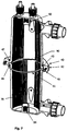
Fig. 7 is a perspective cross-sectional view depicting half of the heat exchanger casing ofFig. 1 ; -
Fig. 8 is a perspective cross-sectional view depicting half of the heat exchanger casing of a second embodiment; -
Fig. 9 is a front view of a flow guide of the heat exchanger ofFig. 1 ; -
Fig. 10 is a detail showing a portion of the flow guide ofFig. 9 ; and -
Fig. 11 depicts a damping means of the heat exchanger ofFigs. 1 and8 . - A
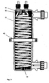
heat exchanger 10 is depicted in the drawings. Theheat exchanger 10 is used in combination with a heat pump for a swimming pool or spa. However, it will be appreciated by those skilled in the art that theheat exchanger 10 can be used in numerous other applications. Theheat exchanger 10 has an outer housing orcasing 12, which defines acentral cavity 13. Theouter casing 12 is formed from two separate injection mouldedplastic halves Fig. 1 , the twocasing halves - The
heat exchanger 10 includes aninlet 20 for receiving heated working fluid, which may be water, refrigerant or another suitable working fluid. Theinlet 20 is coupled to a source of heated working fluid. For example, this may be a roof mounted solar panel water heater, or a gas water heating system or a heat pump. Theinlet 20 is fluidly connected to an internal coolant conduit in the form of acoil tube 30. - In a preferred embodiment, the
coil tube 30 is manufactured from titanium, or another metal or metal alloy having high thermal conductivity properties. Titanium provides inert and robust properties and has a longer life expectancy compared to other typical coil materials such as copper. Advantageously, titanium provides enhanced protection against erosion and corrosion from chlorinated water, ozone, iodine, bromine and salt water. - Alternatively, the
coil tube 30 can be manufactured from a copper base coil which is alloyed or coated with another corrosion resistant material such as nickel, iron, or manganese. - In the embodiment of the
heat exchanger 10 depicted in the drawings, thecoil tube 30 includes two coils. However, thecoil tube 30 may include additional coils, for example three (3) or four (4) tubes defining a series of internal coils and an external coil that are arranged co-axially in relation to each other, and wherein the internal coils are surrounded by the external coil. - As depicted in the embodiment of
Fig. 1 , thecoil tube 30 is a double helical coil arrangement, having an outer helix orcoil 32 and a co-axial inner helix orcoil 34. Theouter coil 32 extends helically from theinlet 20, located at aproximal end 22 of theheat exchanger 10, to adistal end 24 of theheat exchanger 10. Theouter coil 32 is located adjacent to the inner wall of thecasing 12. - At the
distal end 24, theouter coil 32 diverts radially inwardly and defines the starting portion of theinner coil 34, which is located within theouter coil 32. Theinner coil 34 extends helically upwardly, through thecasing 12 to a workingfluid outlet port 26. Theoutlet port 26 returns the working fluid to the heat source, for reheating after heat exchange. - The
heat exchanger 10 includes a locking means in the form of aclamp 40 which secures the twohalves casing 12 together. Theclamp 40 is formed by two corresponding generallysemi-annular clamp members 42. Eachclamp member 42 has a semi-circular cut-out, corresponding generally in size to the outer radius of the clamped portion of theouter casing 12. - The
clamp members 42 each have ahole 44 formed on each side to receive a screw orbolt 46. Twobolts 46 are used to provide a clamping force to pull the twocasing halves - Referring to
Fig. 7 , theclamp members 42 each have a generally U-shaped cross-section include two inclined arms orsidewalls 43, which together define a generally U-shaped annular groove or channel 45. - Also referring to
Fig. 7 , the mouldedplastic halves flange 47. Theflanges 47 each have aninclined surface 49, adapted to mate with theinclined side wall 43 of theclamp members 42. An opposing side of eachflange 47 includes a semi-circular annular groove adapted to receive an O-ring 51. Accordingly, by tightening thebolts 46, theinclined side walls 43 of theclamp members 42 apply a force against theinclined surfaces 49 of theflanges 47. This acts to compress the O-ring 51, resulting in a liquid tight seal between the twohalves casing 12. - The moulded
plastic halves casing 12 are selectively separable and are attached and secured using theclamp 40 in the manner described above. Theclamp 40 permits quick disassembly and reassembly of thecasing 12 for maintenance or repair purposes. When installed around thehousing 12, theclamp 40 secures thecasing 12 and prevents leakage. - Servicing or cleaning of the
coil tube 30 or other internal components can be performed by disassembling thecasing 12 by simply unlocking theclamp 40. Advantageously, theclamp 40 can be removed relatively quickly compared to other means such as a flange and gasket which typically require a large number of screws. - The
casing 12 and clamp 40 are manufactured using a precision moulding process. Thecasing 12 is preferably made of 15% GFPP (glass fibre polypropylene), whilst theclamp 40 is preferably made of 30% GFPP. This assists thecasing 12 and theclamp 40 to be stable in terms of dimensions and resistance to chemicals and heat at high temperature. Advantageously, theheat exchanger 10 is durable and easy to assemble without the need for any further machining processes. - The polymeric components of the
heat exchanger 10, such as thecasing 12, are impervious to rust, corrosion and deterioration. This allows theheat exchanger 10 to be used in various applications at different temperatures. - The precision moulding process generally produces components of consistent quality whereby each part, section and area of the components such as grooves and threads are formed with precision. This permits suitable connections between the
heat exchanger 10 and other related components such as the double row coil and the exterior piping that is to be connected to theheat exchanger 10. - The
heat exchanger 10 includes acold water inlet 50. Thecold water inlet 50 is located at thedistal end 24 of theheat exchanger 10, furthest from the workingfluid inlet 20, such that theheat exchanger 10 is acounter-flow heat exchanger 10, whereby the liquids/fluids enter the exchanger from opposing ends. Thecold water Inlet 50 is designed to receive water from the swimming pool or spa. - As shown in
Fig. 1 , thecasing 12 is formed generally in a cylindrical shape, and thecold water inlet 50 andheated water outlet 60 protrude from thecasing 12, and are located at opposing ends of thecasing 12. - The external surfaces of the
cold water inlet 50 andheated water outlet 60 are threaded to receive halfunion type couplings 90. Thehalf union couplings 90 provide easy connection to plumbing for thecold water inlet 50 andheated water outlet 60. - The interior of the moulded plastic casing halves 14, 15 further comprise
abutment portions flow guide 80. As shown inFig. 2 , theflow guide 80 is supported by afirst abutment portion 92 in the form of a firstannular flange 92 which is formed inside thecasing 12 at theproximal end 22, inside thefirst casing half 14, and asecond abutment portion 94 in the form of aannular flange 94 which is also located inside thecasing 12 at thedistal end 24, inside thesecond casing half 15. - The flow guide 80 is shown in isolation in
Fig. 9 . The flow guide 80 includes abarrel 85 and astem 89 located on two opposing sides of thebarrel 85. The end of each stem 89 includes an engagement formation In the form of anexternal splined connection 81. The splined connections are adapted to mesh with theabutment portions casing 12, which include corresponding internal splines. - The flow guide 80 is located in the centre of the
heat exchanger 10, within the centre of theinner coil 34. The flow guide 80 agitates the water, promoting turbulence within the water flowing through thecavity 13, which advantageously results increased contact with thecoil tube 30 for improved heat exchange. As such, theflow guide 80 increases the flow path of the water over the internal 34 andexternal coil 32 of thecoil tube 30 for maximum heat transfer. - Referring to
Fig. 9 , theflow guide 80 is defined by a generallycylindrical barrel 85 having a plurality of annular bands or alternatively a helically extendingrib 83. The bands orribs 83 are located around the circumference of thebarrel 85, and extend in a direction which is generally perpendicular to the water flow direction through theheat exchanger 10. Theribs 83 provide texture on the outer flow guide 80 surface, and promote turbulence in the water, increasing the performance of the heat extraction process. - The
barrel 85 of theflow guide 80 has a hollow, internal chamber, and a plurality ofopenings 87 are located in the wall of thebarrel 85. Theopenings 87 are in fluid communication with the internal hollow space located within thebarrel 85. A detail showing a portion of the outer wall of thebarrel 85 is shown in isolation inFig. 10 . Theopenings 87 permit water drainage which is useful especially during cold periods such as winter. During winter heat pumps are generally not used. Accordingly, theopenings 87 enable the drainage of any water left in theflow guide 80, which reduces the risk of damage resulting from expansion of water when freezing occurs. - As shown in
Fig. 7 and8 , the internal walls of thecasing 12 include a plurality of longitudinally extendingribs 70. Theribs 70 assist to guide the water passing through theheat exchanger 10 between thecold water inlet 50 and theheated water outlet 60. - The
ribs 70 are cast into the wall of thecasing 12 during manufacture, and extend away from the wall of thecasing 12. However, it will be appreciated that longitudinally extending grooves or channels may be alternatively provided which can be cast or machined into the wall of thecasing 12. - The
heat exchanger 10 includes damping means 90 for limiting the movement of thecoil tube 30. This reduces the amount of operating noise, and reduces the likelihood of cyclical damage resulting from vibration of thecoil tube 30. - The damping means 90 is depicted in isolation in
Fig. 11 . The damping means 90 is a longitudinally extending generallyU-shaped bar 90, which snaps into engagement, or otherwise loosely abuts against the inner wall of thecasing 12, such thatarms 92 of thebar 90 interact with spaces between thelongitudinally extending ribs 70. Theouter coil 32 of thecoil tube 30 abuts against thecentral portion 94 of the U-shaped dampingbar 90, and this limits the amount that theouter coil tube 32 can move or vibrate laterally when water flows through it. The number of damping bars provided 90 depends on the size of theheat exchanger 10. In some embodiments three dampingbars 90 are provided, whilst in larger models of theheat exchanger 10, six or more dampingbars 90 may be provided. - The damping bars 90 can be made from a polymeric materials or synthetic elastic materials such as plastic or rubber. The damping bars 90 extend between the
proximal end 22 and thedistal end 24 of thecasing 12. - When water exits from the
heat exchanger 10 through theoutlet 60, the pool water has extracted some of the thermal energy contained within the working fluid source, and is hotter than the water at theinlet 50. The heated water is then returned to the pool, to locally raise the water temperature within the pool. In contrast the working fluid exiting theoutlet 26 is subsequently at a lower temperature, and is returned to the heat source for further heating and subsequent recirculation through theheat exchanger 10. - Advantageously, the
double coil 30 maximises heat exchange between the hot and cold water sources, by increasing the water contact surface area. - As shown in
Fig. 1 , atube gland 112 manufactured from a moulded engineering plastic is located on each of the tube ends for sealing theinlet 20 andoutlet 26 relative to thecasing 12. - The embodiment of
Figs. 1 to 7 relate to a first size of theheat exchanger 10, in which the join between the casing halves 14, 15 is located approximately in the centre of theheat exchanger 10. In an alternative embodiment depicted inFig. 8 , thelower half 15 of the casing is smaller, such that the join between the upper and lower casing halves 14, 15 is located below the centre of the heat exchanger. -
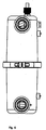
Fig. 3 depicts a rear view of theheat exchanger 10. Thepre-moulded casing 12 has a plurality of apertures. Two of the aperture are dedicated to allow the tube ends of thedouble row coil 30 to penetrate through the housing as shown inFigs. 1 and2 . In addition other apertures are provided to receive twonipples 110 located externally on thecasing 12 as shown inFig. 3 , and afurther nipple 114 which is located on thewater inlet 50. - In order to determine the temperature of water inside the
casing 12, athermowell temperature sensor 100 is provided on theheat exchanger 10casing 12. Thetemperature sensor 100 senses the temperature of the water and activates an electronic circuit that is connected to thetemperature sensor 100 when the temperature reaches a set point. For example, when a set temperature is reached, a compressor of a heating system will be switched off in order to stop a refrigerant from flowing through thedouble row coil 30. - The
nipples 110 and/or 114 are connectable to a pressure switch for sensing and measuring water pressure. For example, when no water is flowing through theheat exchanger 10, the compressor will be switched off. - The assembly or re-assembly of the
heat exchanger 10 will now be described. When a technician wishes to assemble theheat exchanger 10 for example during maintenance or repair, thecoil tube 30 is re-connected if it was removed. The technician then inserts theflow guide 80, such that theexternal splined connection 81 located at one end of theflow guide 80 meshes with one of theabutment portions half 14 thecasing 12. The O-ring 51 is then seated on one of the grooves located in one of theflanges 47. The other half of thecasing 12 is then positioned such that the flow guide 80 passes through the centre of theinner coil 34. - As the two
casing halves external splined connection 81 at the opposing end of the flow guide meshes with thesecond half 15 of thecasing 12, and the O-ring 51 becomes located between the two grooves. - The
clamp members 42 are then located around theflanges 47 on thecasing 12. The technician then tightens thebolts 46, to compress the O-ring 51 to a suitable degree to achieve a water tight seal. Theheat exchanger 10 can be readily opened in a manner being the reverse of that described above for subsequent maintenance or repairs. - The design and the method of constructing the
heat exchanger 10 permits the number of apertures or sensors to be increased or reduced according to requirement and the use of the sensors is not limited to temperature and flow sensors. - Although the invention has been described with reference to specific examples, it will be appreciated by those skilled in the art that the invention may be embodied in many other forms.
Claims (14)
- A heat exchanger (10) comprising:a housing (12);a fluid flow conduit located within a cavity formed in the housing (12), the fluid flow conduit including an outer tube located adjacent to an inner wall of the housing and an inner tube in fluid communication with the outer tube, the inner tube being located between the outer tube and a longitudinal axis of the housing (12), wherein the outer tube defines a first helix extending generally co-axially with the longitudinal axis and the inner tube defines a second helix also extending generally co-axially with the longitudinal axis;an inlet port located on the housing (12), the inlet port being in fluid communication with the cavity;an outlet port located on the housing (12), the outlet port being in fluid communication with the cavity;a flow guide (80) located between the inner tube and the longitudinal axis of the housing (12), the flow guide (80) being adapted to agitate water flowing between the inlet port and the outlet port, wherein:the housing (12) includes a first section and a second section that are selectively detachable relative to each other; andthe flow guide (80) includes two stems which are located at opposing ends of the flow guide (80), each stem including a first engagement formation for engaging with a corresponding second engagement formation formed in the housing, wherein the flow guide (80) includes an elongate cylindrical member having a textured outer surface.
- The heat exchanger (10) of claim 1, wherein the outer surface includes a plurality of annular ribs or a helical rib.
- The heat exchanger (10) of claim 1, wherein the cylindrical member is hollow and includes a plurality of apertures for permitting drainage of water.
- The heat exchanger (10) of any one of the preceding claims, further comprising a plurality of longitudinally extending ribs or grooves formed on the inner wall of the housing (12).
- The heat exchanger (10) of claim 1, wherein the first and second sections each include an annular flange, the annular flange including a first side having an annular groove and an opposing second side having an inclined surface.
- The heat exchanger (10) of claim 1, wherein the housing (12) includes a removable clamp for securing the first section to the second section.
- The heat exchanger (10) of claim 6, wherein the clamp has a generally U-shaped profile, defining two inclined arms, each arm being adapted to engage with one of said annular flange inclined surfaces, further wherein the clamp is adjustable to pull the first and second sections together to compress a gasket or O-ring.
- The heat exchanger (10) of any one of the preceding claims, wherein the housing is manufactured from a glass fibre polypropylene (GFPP).
- The heat exchanger (10) of claim 6, wherein the clamp includes two band portions which are securable together with fasteners.
- The heat exchanger (10) of any one of the preceding claims, wherein the fluid flow conduit is manufactured from titanium.
- The heat exchanger (10) of any one of the preceding claims, wherein the housing includes one or more apertures for receiving a temperature and/or pressure sensor.
- The heat exchanger (10) of claim 1, wherein the first and second engagement formations are corresponding male and female spline connections.
- The heat exchanger (10) of any one of the preceding claims, further comprising at least one damping means located between the inner wall of the housing and the outer tube.
- The heat exchanger (10) of claim 13, wherein the damping means includes an engagement formation adapted to engage with the inner wall, further wherein there are three or more damping means spaced around a circumference of the cavity.
Applications Claiming Priority (3)
| Application Number | Priority Date | Filing Date | Title |
|---|---|---|---|
| CN 201220315707 CN202675951U (en) | 2012-06-29 | 2012-06-29 | Heat exchanger |
| MYPI2012004453 | 2012-10-05 | ||
| PCT/AU2013/000289 WO2014000017A1 (en) | 2012-06-29 | 2013-03-22 | Heat exchanger |
Publications (3)
| Publication Number | Publication Date |
|---|---|
| EP2844941A1 EP2844941A1 (en) | 2015-03-11 |
| EP2844941A4 EP2844941A4 (en) | 2016-06-01 |
| EP2844941B1 true EP2844941B1 (en) | 2017-07-26 |
Family
ID=48874639
Family Applications (1)
| Application Number | Title | Priority Date | Filing Date |
|---|---|---|---|
| EP13809578.1A Not-in-force EP2844941B1 (en) | 2012-06-29 | 2013-03-22 | Heat exchanger |
Country Status (6)
| Country | Link |
|---|---|
| US (1) | US9683785B2 (en) |
| EP (1) | EP2844941B1 (en) |
| AU (2) | AU2013284326B2 (en) |
| CA (1) | CA2871518A1 (en) |
| MY (1) | MY183553A (en) |
| WO (1) | WO2014000017A1 (en) |
Families Citing this family (9)
| Publication number | Priority date | Publication date | Assignee | Title |
|---|---|---|---|---|
| DK2937657T3 (en) * | 2014-04-25 | 2020-01-06 | Franke Technology & Trademark | HEAT EXCHANGE |
| US9897385B2 (en) | 2015-02-20 | 2018-02-20 | Therma-Stor LLC | Helical coil heating apparatus and method of operation |
| NL2014599B1 (en) * | 2015-04-08 | 2017-01-20 | Van Kessel Beheer B V | Heat Exchanger. |
| EP3128278B1 (en) * | 2015-08-06 | 2018-06-20 | Linde Aktiengesellschaft | Feeding and removal of pipe streams with interim temperature in coiled heat exchangers |
| WO2017178120A1 (en) * | 2016-04-14 | 2017-10-19 | Linde Aktiengesellschaft | Wound heat exchanger |
| IT201600077849A1 (en) * | 2016-07-25 | 2018-01-25 | Gruppo Cimbali Spa | Device for heating fluids continuously. |
| CN112432520A (en) * | 2020-10-12 | 2021-03-02 | 浦江春生夏长环保科技有限公司 | Geothermal circulation heat exchange assembly |
| US11530645B2 (en) * | 2021-02-17 | 2022-12-20 | Pratt & Whitney Canada Corp. | Fluid cooler for a gas turbine engine |
| US20220316823A1 (en) * | 2021-03-30 | 2022-10-06 | Rheem Manufacturing Company | Corrosion prevention for heat exchanger devices and pool heaters |
Family Cites Families (21)
| Publication number | Priority date | Publication date | Assignee | Title |
|---|---|---|---|---|
| FR2034754A6 (en) * | 1968-03-06 | 1970-12-18 | Mille Gaston | |
| DE2236954A1 (en) * | 1971-07-27 | 1973-02-08 | Alfa Romeo Spa | HEAT EXCHANGER |
| US4462220A (en) * | 1981-10-30 | 1984-07-31 | Gerlach Industries | Cooling sensor for refrigeration system |
| US4872503A (en) * | 1986-03-13 | 1989-10-10 | Marriner Raymond E | Air heat exchanger |
| JPH0731016B2 (en) * | 1987-03-05 | 1995-04-10 | 日本電装株式会社 | Heat exchanger assembly structure |
| US4907418A (en) * | 1988-11-14 | 1990-03-13 | Defazio Louis C | Liquid heating system particularly for use with swimming pools or the like |
| US5379832A (en) | 1992-02-18 | 1995-01-10 | Aqua Systems, Inc. | Shell and coil heat exchanger |
| US5845704A (en) | 1997-05-16 | 1998-12-08 | Flowserve Management Company | Heat exchanger baffle design |
| US6076597A (en) * | 1997-12-31 | 2000-06-20 | Flowserve Management Company | Helical coil heat exchanger with removable end plates |
| US6293335B1 (en) * | 1999-06-24 | 2001-09-25 | Aquacal, Inc. | Method and apparatus for optimizing heat transfer in a tube and shell heat exchanger |
| DE10051756B4 (en) * | 2000-10-18 | 2007-03-01 | Witzenmann Gmbh | Heat exchanger for swimming pools |
| US6499534B1 (en) | 2002-02-15 | 2002-12-31 | Aquacal | Heat exchanger with two-stage heat transfer |
| NZ523962A (en) * | 2003-01-31 | 2004-10-29 | Energy Saving Concepts Ltd | Heat exchanger with multiple turbulent flow paths |
| ES2306214T3 (en) * | 2004-07-22 | 2008-11-01 | P.S.A. | HEAT EXCHANGER OF SERPENTIN (ES) AND HELICOIDAL NERVADURA (S) SEPARATION. |
| IES20050246A2 (en) * | 2005-04-25 | 2006-11-01 | Aidan Casey Senior | A clamp |
| US20080264617A1 (en) | 2007-04-26 | 2008-10-30 | David Martin | Heat exchanger |
| DE102007033166A1 (en) * | 2007-07-17 | 2009-01-22 | WTS Kereskedelmi és Szolgáltató Kft. | heat exchangers |
| US20100096115A1 (en) * | 2008-10-07 | 2010-04-22 | Donald Charles Erickson | Multiple concentric cylindrical co-coiled heat exchanger |
| US20120174605A1 (en) | 2009-09-28 | 2012-07-12 | Carrier Corporation | Liquid-cooled heat exchanger in a vapor compression refrigeration system |
| US20110289905A1 (en) | 2010-06-01 | 2011-12-01 | Delphi Technologies, Inc. | Exhaust gas heat recovery heat exchanger |
| US20110303400A1 (en) * | 2010-06-15 | 2011-12-15 | Pb Heat, Llc | Counterflow heat exchanger |
-
2013
- 2013-03-22 EP EP13809578.1A patent/EP2844941B1/en not_active Not-in-force
- 2013-03-22 US US14/403,627 patent/US9683785B2/en not_active Expired - Fee Related
- 2013-03-22 WO PCT/AU2013/000289 patent/WO2014000017A1/en active Application Filing
- 2013-03-22 CA CA2871518A patent/CA2871518A1/en not_active Abandoned
- 2013-03-22 AU AU2013284326A patent/AU2013284326B2/en not_active Ceased
- 2013-03-22 MY MYPI2014703961A patent/MY183553A/en unknown
- 2013-07-01 AU AU2013100894A patent/AU2013100894A4/en not_active Ceased
Non-Patent Citations (1)
| Title |
|---|
| None * |
Also Published As
| Publication number | Publication date |
|---|---|
| CA2871518A1 (en) | 2014-01-03 |
| MY183553A (en) | 2021-02-26 |
| WO2014000017A1 (en) | 2014-01-03 |
| US9683785B2 (en) | 2017-06-20 |
| AU2013100894A4 (en) | 2013-08-01 |
| AU2013284326A1 (en) | 2014-11-13 |
| EP2844941A1 (en) | 2015-03-11 |
| EP2844941A4 (en) | 2016-06-01 |
| AU2013284326B2 (en) | 2017-07-27 |
| US20150136368A1 (en) | 2015-05-21 |
Similar Documents
| Publication | Publication Date | Title |
|---|---|---|
| EP2844941B1 (en) | Heat exchanger | |
| CN104412059B (en) | Heat exchanger | |
| US6499534B1 (en) | Heat exchanger with two-stage heat transfer | |
| US20170108279A1 (en) | Heat exchanger with multiple flow tubes for fluid circulation | |
| US4462463A (en) | Triple pass heat exchanger | |
| RU2498757C2 (en) | Dispenser for cold and hot water | |
| AU2017206160B2 (en) | Heat Exchanger | |
| CN204923968U (en) | Vortex is adverse current double -pipe heat exchanger entirely | |
| EP3117170B1 (en) | Heat exchanger for low temperatures | |
| JP6277713B2 (en) | Double tube heat exchanger | |
| KR20160069090A (en) | Cold Water Generating Tank And Water Cooler Having the Same | |
| KR20160069091A (en) | Cold Water Generating Tank And Water Cooler Having the Same | |
| KR102066478B1 (en) | Apparatus for cooling fluid and manufacturing method thereof | |
| KR20160131787A (en) | Cooling Device For Water Purifier By Using Direct Contact Method | |
| WO2009008698A2 (en) | Heat exchanger | |
| KR102088374B1 (en) | Heat Exchanger for Chiller | |
| JP2003240457A (en) | Heat exchanger for hot-water supply | |
| CN217560414U (en) | Combined tube type heat exchanger convenient to disassemble and assemble | |
| KR102475164B1 (en) | Finless type shell and double tube heat exchanger with electric heating device | |
| CN211903826U (en) | Detachable heat exchanger | |
| JP4016375B2 (en) | Heat exchanger for hot water supply | |
| CN104990441A (en) | Spiral heat exchange pipe | |
| JPH0226157B2 (en) | ||
| CN105258541A (en) | Superconducting heat exchanger | |
| JP2003176950A (en) | Tank device for heating water |
Legal Events
| Date | Code | Title | Description |
|---|---|---|---|
| PUAI | Public reference made under article 153(3) epc to a published international application that has entered the european phase |
Free format text: ORIGINAL CODE: 0009012 |
|
| 17P | Request for examination filed |
Effective date: 20141205 |
|
| AK | Designated contracting states |
Kind code of ref document: A1 Designated state(s): AL AT BE BG CH CY CZ DE DK EE ES FI FR GB GR HR HU IE IS IT LI LT LU LV MC MK MT NL NO PL PT RO RS SE SI SK SM TR |
|
| AX | Request for extension of the european patent |
Extension state: BA ME |
|
| DAX | Request for extension of the european patent (deleted) | ||
| RIC1 | Information provided on ipc code assigned before grant |
Ipc: F28F 21/06 20060101ALI20160111BHEP Ipc: F28F 9/013 20060101ALI20160111BHEP Ipc: F28D 7/04 20060101ALI20160111BHEP Ipc: F28D 7/10 20060101ALI20160111BHEP Ipc: F28D 7/14 20060101ALI20160111BHEP Ipc: F28D 7/02 20060101AFI20160111BHEP |
|
| RA4 | Supplementary search report drawn up and despatched (corrected) |
Effective date: 20160503 |
|
| RIC1 | Information provided on ipc code assigned before grant |
Ipc: F28D 7/02 20060101AFI20160426BHEP Ipc: F28F 21/06 20060101ALI20160426BHEP Ipc: F28D 7/04 20060101ALI20160426BHEP Ipc: F28F 9/013 20060101ALI20160426BHEP Ipc: F28D 7/14 20060101ALI20160426BHEP Ipc: F28D 7/10 20060101ALI20160426BHEP |
|
| GRAP | Despatch of communication of intention to grant a patent |
Free format text: ORIGINAL CODE: EPIDOSNIGR1 |
|
| INTG | Intention to grant announced |
Effective date: 20170419 |
|
| GRAS | Grant fee paid |
Free format text: ORIGINAL CODE: EPIDOSNIGR3 |
|
| GRAA | (expected) grant |
Free format text: ORIGINAL CODE: 0009210 |
|
| AK | Designated contracting states |
Kind code of ref document: B1 Designated state(s): AL AT BE BG CH CY CZ DE DK EE ES FI FR GB GR HR HU IE IS IT LI LT LU LV MC MK MT NL NO PL PT RO RS SE SI SK SM TR |
|
| REG | Reference to a national code |
Ref country code: GB Ref legal event code: FG4D |
|
| REG | Reference to a national code |
Ref country code: CH Ref legal event code: EP |
|
| REG | Reference to a national code |
Ref country code: AT Ref legal event code: REF Ref document number: 912714 Country of ref document: AT Kind code of ref document: T Effective date: 20170815 |
|
| REG | Reference to a national code |
Ref country code: IE Ref legal event code: FG4D |
|
| REG | Reference to a national code |
Ref country code: DE Ref legal event code: R096 Ref document number: 602013024158 Country of ref document: DE |
|
| REG | Reference to a national code |
Ref country code: NL Ref legal event code: MP Effective date: 20170726 |
|
| REG | Reference to a national code |
Ref country code: LT Ref legal event code: MG4D |
|
| REG | Reference to a national code |
Ref country code: AT Ref legal event code: MK05 Ref document number: 912714 Country of ref document: AT Kind code of ref document: T Effective date: 20170726 |
|
| PG25 | Lapsed in a contracting state [announced via postgrant information from national office to epo] |
Ref country code: AT Free format text: LAPSE BECAUSE OF FAILURE TO SUBMIT A TRANSLATION OF THE DESCRIPTION OR TO PAY THE FEE WITHIN THE PRESCRIBED TIME-LIMIT Effective date: 20170726 Ref country code: LT Free format text: LAPSE BECAUSE OF FAILURE TO SUBMIT A TRANSLATION OF THE DESCRIPTION OR TO PAY THE FEE WITHIN THE PRESCRIBED TIME-LIMIT Effective date: 20170726 Ref country code: HR Free format text: LAPSE BECAUSE OF FAILURE TO SUBMIT A TRANSLATION OF THE DESCRIPTION OR TO PAY THE FEE WITHIN THE PRESCRIBED TIME-LIMIT Effective date: 20170726 Ref country code: NL Free format text: LAPSE BECAUSE OF FAILURE TO SUBMIT A TRANSLATION OF THE DESCRIPTION OR TO PAY THE FEE WITHIN THE PRESCRIBED TIME-LIMIT Effective date: 20170726 Ref country code: NO Free format text: LAPSE BECAUSE OF FAILURE TO SUBMIT A TRANSLATION OF THE DESCRIPTION OR TO PAY THE FEE WITHIN THE PRESCRIBED TIME-LIMIT Effective date: 20171026 Ref country code: SE Free format text: LAPSE BECAUSE OF FAILURE TO SUBMIT A TRANSLATION OF THE DESCRIPTION OR TO PAY THE FEE WITHIN THE PRESCRIBED TIME-LIMIT Effective date: 20170726 Ref country code: FI Free format text: LAPSE BECAUSE OF FAILURE TO SUBMIT A TRANSLATION OF THE DESCRIPTION OR TO PAY THE FEE WITHIN THE PRESCRIBED TIME-LIMIT Effective date: 20170726 |
|
| PG25 | Lapsed in a contracting state [announced via postgrant information from national office to epo] |
Ref country code: PL Free format text: LAPSE BECAUSE OF FAILURE TO SUBMIT A TRANSLATION OF THE DESCRIPTION OR TO PAY THE FEE WITHIN THE PRESCRIBED TIME-LIMIT Effective date: 20170726 Ref country code: ES Free format text: LAPSE BECAUSE OF FAILURE TO SUBMIT A TRANSLATION OF THE DESCRIPTION OR TO PAY THE FEE WITHIN THE PRESCRIBED TIME-LIMIT Effective date: 20170726 Ref country code: BG Free format text: LAPSE BECAUSE OF FAILURE TO SUBMIT A TRANSLATION OF THE DESCRIPTION OR TO PAY THE FEE WITHIN THE PRESCRIBED TIME-LIMIT Effective date: 20171026 Ref country code: RS Free format text: LAPSE BECAUSE OF FAILURE TO SUBMIT A TRANSLATION OF THE DESCRIPTION OR TO PAY THE FEE WITHIN THE PRESCRIBED TIME-LIMIT Effective date: 20170726 Ref country code: GR Free format text: LAPSE BECAUSE OF FAILURE TO SUBMIT A TRANSLATION OF THE DESCRIPTION OR TO PAY THE FEE WITHIN THE PRESCRIBED TIME-LIMIT Effective date: 20171027 Ref country code: LV Free format text: LAPSE BECAUSE OF FAILURE TO SUBMIT A TRANSLATION OF THE DESCRIPTION OR TO PAY THE FEE WITHIN THE PRESCRIBED TIME-LIMIT Effective date: 20170726 Ref country code: IS Free format text: LAPSE BECAUSE OF FAILURE TO SUBMIT A TRANSLATION OF THE DESCRIPTION OR TO PAY THE FEE WITHIN THE PRESCRIBED TIME-LIMIT Effective date: 20171126 |
|
| PG25 | Lapsed in a contracting state [announced via postgrant information from national office to epo] |
Ref country code: CZ Free format text: LAPSE BECAUSE OF FAILURE TO SUBMIT A TRANSLATION OF THE DESCRIPTION OR TO PAY THE FEE WITHIN THE PRESCRIBED TIME-LIMIT Effective date: 20170726 Ref country code: DK Free format text: LAPSE BECAUSE OF FAILURE TO SUBMIT A TRANSLATION OF THE DESCRIPTION OR TO PAY THE FEE WITHIN THE PRESCRIBED TIME-LIMIT Effective date: 20170726 Ref country code: RO Free format text: LAPSE BECAUSE OF FAILURE TO SUBMIT A TRANSLATION OF THE DESCRIPTION OR TO PAY THE FEE WITHIN THE PRESCRIBED TIME-LIMIT Effective date: 20170726 |
|
| REG | Reference to a national code |
Ref country code: DE Ref legal event code: R097 Ref document number: 602013024158 Country of ref document: DE |
|
| PG25 | Lapsed in a contracting state [announced via postgrant information from national office to epo] |
Ref country code: SM Free format text: LAPSE BECAUSE OF FAILURE TO SUBMIT A TRANSLATION OF THE DESCRIPTION OR TO PAY THE FEE WITHIN THE PRESCRIBED TIME-LIMIT Effective date: 20170726 Ref country code: EE Free format text: LAPSE BECAUSE OF FAILURE TO SUBMIT A TRANSLATION OF THE DESCRIPTION OR TO PAY THE FEE WITHIN THE PRESCRIBED TIME-LIMIT Effective date: 20170726 Ref country code: IT Free format text: LAPSE BECAUSE OF FAILURE TO SUBMIT A TRANSLATION OF THE DESCRIPTION OR TO PAY THE FEE WITHIN THE PRESCRIBED TIME-LIMIT Effective date: 20170726 Ref country code: SK Free format text: LAPSE BECAUSE OF FAILURE TO SUBMIT A TRANSLATION OF THE DESCRIPTION OR TO PAY THE FEE WITHIN THE PRESCRIBED TIME-LIMIT Effective date: 20170726 |
|
| PLBE | No opposition filed within time limit |
Free format text: ORIGINAL CODE: 0009261 |
|
| STAA | Information on the status of an ep patent application or granted ep patent |
Free format text: STATUS: NO OPPOSITION FILED WITHIN TIME LIMIT |
|
| 26N | No opposition filed |
Effective date: 20180430 |
|
| PG25 | Lapsed in a contracting state [announced via postgrant information from national office to epo] |
Ref country code: SI Free format text: LAPSE BECAUSE OF FAILURE TO SUBMIT A TRANSLATION OF THE DESCRIPTION OR TO PAY THE FEE WITHIN THE PRESCRIBED TIME-LIMIT Effective date: 20170726 |
|
| REG | Reference to a national code |
Ref country code: DE Ref legal event code: R119 Ref document number: 602013024158 Country of ref document: DE |
|
| REG | Reference to a national code |
Ref country code: CH Ref legal event code: PL |
|
| PG25 | Lapsed in a contracting state [announced via postgrant information from national office to epo] |
Ref country code: MC Free format text: LAPSE BECAUSE OF FAILURE TO SUBMIT A TRANSLATION OF THE DESCRIPTION OR TO PAY THE FEE WITHIN THE PRESCRIBED TIME-LIMIT Effective date: 20170726 |
|
| REG | Reference to a national code |
Ref country code: BE Ref legal event code: MM Effective date: 20180331 |
|
| REG | Reference to a national code |
Ref country code: IE Ref legal event code: MM4A |
|
| PG25 | Lapsed in a contracting state [announced via postgrant information from national office to epo] |
Ref country code: LU Free format text: LAPSE BECAUSE OF NON-PAYMENT OF DUE FEES Effective date: 20180322 |
|
| PG25 | Lapsed in a contracting state [announced via postgrant information from national office to epo] |
Ref country code: DE Free format text: LAPSE BECAUSE OF NON-PAYMENT OF DUE FEES Effective date: 20181002 Ref country code: IE Free format text: LAPSE BECAUSE OF NON-PAYMENT OF DUE FEES Effective date: 20180322 |
|
| PG25 | Lapsed in a contracting state [announced via postgrant information from national office to epo] |
Ref country code: BE Free format text: LAPSE BECAUSE OF NON-PAYMENT OF DUE FEES Effective date: 20180331 Ref country code: CH Free format text: LAPSE BECAUSE OF NON-PAYMENT OF DUE FEES Effective date: 20180331 Ref country code: LI Free format text: LAPSE BECAUSE OF NON-PAYMENT OF DUE FEES Effective date: 20180331 |
|
| PG25 | Lapsed in a contracting state [announced via postgrant information from national office to epo] |
Ref country code: FR Free format text: LAPSE BECAUSE OF NON-PAYMENT OF DUE FEES Effective date: 20180331 |
|
| PGFP | Annual fee paid to national office [announced via postgrant information from national office to epo] |
Ref country code: GB Payment date: 20190314 Year of fee payment: 7 |
|
| PG25 | Lapsed in a contracting state [announced via postgrant information from national office to epo] |
Ref country code: MT Free format text: LAPSE BECAUSE OF NON-PAYMENT OF DUE FEES Effective date: 20180322 |
|
| PG25 | Lapsed in a contracting state [announced via postgrant information from national office to epo] |
Ref country code: TR Free format text: LAPSE BECAUSE OF FAILURE TO SUBMIT A TRANSLATION OF THE DESCRIPTION OR TO PAY THE FEE WITHIN THE PRESCRIBED TIME-LIMIT Effective date: 20170726 |
|
| PG25 | Lapsed in a contracting state [announced via postgrant information from national office to epo] |
Ref country code: PT Free format text: LAPSE BECAUSE OF FAILURE TO SUBMIT A TRANSLATION OF THE DESCRIPTION OR TO PAY THE FEE WITHIN THE PRESCRIBED TIME-LIMIT Effective date: 20170726 |
|
| PG25 | Lapsed in a contracting state [announced via postgrant information from national office to epo] |
Ref country code: CY Free format text: LAPSE BECAUSE OF FAILURE TO SUBMIT A TRANSLATION OF THE DESCRIPTION OR TO PAY THE FEE WITHIN THE PRESCRIBED TIME-LIMIT Effective date: 20170726 Ref country code: HU Free format text: LAPSE BECAUSE OF FAILURE TO SUBMIT A TRANSLATION OF THE DESCRIPTION OR TO PAY THE FEE WITHIN THE PRESCRIBED TIME-LIMIT; INVALID AB INITIO Effective date: 20130322 Ref country code: MK Free format text: LAPSE BECAUSE OF NON-PAYMENT OF DUE FEES Effective date: 20170726 |
|
| PG25 | Lapsed in a contracting state [announced via postgrant information from national office to epo] |
Ref country code: AL Free format text: LAPSE BECAUSE OF FAILURE TO SUBMIT A TRANSLATION OF THE DESCRIPTION OR TO PAY THE FEE WITHIN THE PRESCRIBED TIME-LIMIT Effective date: 20170726 |
|
| GBPC | Gb: european patent ceased through non-payment of renewal fee |
Effective date: 20200322 |
|
| PG25 | Lapsed in a contracting state [announced via postgrant information from national office to epo] |
Ref country code: GB Free format text: LAPSE BECAUSE OF NON-PAYMENT OF DUE FEES Effective date: 20200322 |