EP2844883B1 - Bush assembly - Google Patents
Bush assembly Download PDFInfo
- Publication number
- EP2844883B1 EP2844883B1 EP13719154.0A EP13719154A EP2844883B1 EP 2844883 B1 EP2844883 B1 EP 2844883B1 EP 13719154 A EP13719154 A EP 13719154A EP 2844883 B1 EP2844883 B1 EP 2844883B1
- Authority
- EP
- European Patent Office
- Prior art keywords
- bush
- seal member
- component
- sealant
- bore
- Prior art date
- Legal status (The legal status is an assumption and is not a legal conclusion. Google has not performed a legal analysis and makes no representation as to the accuracy of the status listed.)
- Active
Links
Images





Classifications
-
- B—PERFORMING OPERATIONS; TRANSPORTING
- B25—HAND TOOLS; PORTABLE POWER-DRIVEN TOOLS; MANIPULATORS
- B25B—TOOLS OR BENCH DEVICES NOT OTHERWISE PROVIDED FOR, FOR FASTENING, CONNECTING, DISENGAGING, OR HOLDING
- B25B27/00—Hand tools, specially adapted for fitting together or separating parts or objects whether or not involving some deformation, not otherwise provided for
- B25B27/0028—Tools for removing or installing seals
-
- F—MECHANICAL ENGINEERING; LIGHTING; HEATING; WEAPONS; BLASTING
- F16—ENGINEERING ELEMENTS AND UNITS; GENERAL MEASURES FOR PRODUCING AND MAINTAINING EFFECTIVE FUNCTIONING OF MACHINES OR INSTALLATIONS; THERMAL INSULATION IN GENERAL
- F16B—DEVICES FOR FASTENING OR SECURING CONSTRUCTIONAL ELEMENTS OR MACHINE PARTS TOGETHER, e.g. NAILS, BOLTS, CIRCLIPS, CLAMPS, CLIPS OR WEDGES; JOINTS OR JOINTING
- F16B43/00—Washers or equivalent devices; Other devices for supporting bolt-heads or nuts
- F16B43/001—Washers or equivalent devices; Other devices for supporting bolt-heads or nuts for sealing or insulation
-
- F—MECHANICAL ENGINEERING; LIGHTING; HEATING; WEAPONS; BLASTING
- F16—ENGINEERING ELEMENTS AND UNITS; GENERAL MEASURES FOR PRODUCING AND MAINTAINING EFFECTIVE FUNCTIONING OF MACHINES OR INSTALLATIONS; THERMAL INSULATION IN GENERAL
- F16C—SHAFTS; FLEXIBLE SHAFTS; ELEMENTS OR CRANKSHAFT MECHANISMS; ROTARY BODIES OTHER THAN GEARING ELEMENTS; BEARINGS
- F16C17/00—Sliding-contact bearings for exclusively rotary movement
- F16C17/02—Sliding-contact bearings for exclusively rotary movement for radial load only
-
- F—MECHANICAL ENGINEERING; LIGHTING; HEATING; WEAPONS; BLASTING
- F16—ENGINEERING ELEMENTS AND UNITS; GENERAL MEASURES FOR PRODUCING AND MAINTAINING EFFECTIVE FUNCTIONING OF MACHINES OR INSTALLATIONS; THERMAL INSULATION IN GENERAL
- F16C—SHAFTS; FLEXIBLE SHAFTS; ELEMENTS OR CRANKSHAFT MECHANISMS; ROTARY BODIES OTHER THAN GEARING ELEMENTS; BEARINGS
- F16C33/00—Parts of bearings; Special methods for making bearings or parts thereof
- F16C33/72—Sealings
- F16C33/74—Sealings of sliding-contact bearings
-
- F—MECHANICAL ENGINEERING; LIGHTING; HEATING; WEAPONS; BLASTING
- F16—ENGINEERING ELEMENTS AND UNITS; GENERAL MEASURES FOR PRODUCING AND MAINTAINING EFFECTIVE FUNCTIONING OF MACHINES OR INSTALLATIONS; THERMAL INSULATION IN GENERAL
- F16J—PISTONS; CYLINDERS; SEALINGS
- F16J15/00—Sealings
- F16J15/02—Sealings between relatively-stationary surfaces
- F16J15/06—Sealings between relatively-stationary surfaces with solid packing compressed between sealing surfaces
-
- B—PERFORMING OPERATIONS; TRANSPORTING
- B23—MACHINE TOOLS; METAL-WORKING NOT OTHERWISE PROVIDED FOR
- B23Q—DETAILS, COMPONENTS, OR ACCESSORIES FOR MACHINE TOOLS, e.g. ARRANGEMENTS FOR COPYING OR CONTROLLING; MACHINE TOOLS IN GENERAL CHARACTERISED BY THE CONSTRUCTION OF PARTICULAR DETAILS OR COMPONENTS; COMBINATIONS OR ASSOCIATIONS OF METAL-WORKING MACHINES, NOT DIRECTED TO A PARTICULAR RESULT
- B23Q1/00—Members which are comprised in the general build-up of a form of machine, particularly relatively large fixed members
- B23Q1/25—Movable or adjustable work or tool supports
-
- F—MECHANICAL ENGINEERING; LIGHTING; HEATING; WEAPONS; BLASTING
- F16—ENGINEERING ELEMENTS AND UNITS; GENERAL MEASURES FOR PRODUCING AND MAINTAINING EFFECTIVE FUNCTIONING OF MACHINES OR INSTALLATIONS; THERMAL INSULATION IN GENERAL
- F16C—SHAFTS; FLEXIBLE SHAFTS; ELEMENTS OR CRANKSHAFT MECHANISMS; ROTARY BODIES OTHER THAN GEARING ELEMENTS; BEARINGS
- F16C2326/00—Articles relating to transporting
- F16C2326/01—Parts of vehicles in general
Definitions
- the invention relates to a bush assembly; to a kit of parts for forming a bush assembly; to a method for sealing a bush; and to a clamping tool for forming a bush assembly.
- a bush may be fitted in a bore in a component to provide an inner surface within the bore.
- the inner surface may, for example, provide a bearing surface for receiving a rod or shaft which passes through or into the component.
- the bush may have a flange which locates the bush within the bore and covers the interface between the bush and the bore surface.
- the performance of the bush may be reduced, for example due to degradation of the bush and/or the bore surface.
- Degradation of the interface between the bush and the bore may occur due to contamination, for example by water, oil, dirt or debris, resulting in surface corrosion of the bush and/or bore.
- the flange may act to reduce contamination of the interface between the bush and the bore, and a layer of sealant may be applied over the bush flange and the surface of the component to seal the bush.
- contamination/corrosion of the bush may still occur, particularly if the layer of sealant becomes damaged or degraded, for example due to mechanical wear, corrosion or age hardening.
- GB 2359604 discloses a method for producing a liquid-tight joint, for instance for an aircraft fuel tank, involving at least two structural components provided with surfaces to be sealingly joined. A continuous layer of adhesive is applied to at least one of the surfaces and then the surfaces are glued and thus sealed together. A series of holes are then drilled through the components and a self sealing fixing element is fitted and fixed in each of the holes.
- the invention relates to a seal for sealing a bush assembly.
- the seal includes a seal member which sits over a flange of the bush which is fitted in a bore of a component and a material for sealing between the seal member and the flange/component.
- a first aspect of the invention provides a bush assembly as claimed in claim 1.
- a second aspect of the invention provides a kit of parts for forming a bush assembly as claimed in claim 13.
- a third aspect of the invention provides a method for sealing a bush as claimed in claim 14.
- a fourth aspect of the invention provides a clamping tool for applying a clamping force for sealing a bush installed in a bore in a component as claimed in claim 15.
- the seal assembly may be adapted to substantially prevent the ingress of contaminants into the interface between the flange and the surface of the component, for example to prevent the ingress of water or oil or dirt or debris.
- the seal assembly may, therefore, reduce or eliminate the ingress of water and/or any other contaminants into the interface between the bush and the surface of the bore.
- the seal assembly may reduce the rate of degradation of the bush and/or the component, thereby reducing the need for maintenance activities, for example re-boring of the bore and replacement of the bush or replacement of the component.
- the layer of sealant has both adhesive and sealing properties.
- the layer of sealant may comprise a conventional sealant or aerospace sealant, for example an epoxy sealant or two part epoxy sealant such as aerospace sealant PR-2001 under ABP 4-5142.
- the aerospace sealant may be used in conjunction with an adhesion promoter.
- the layer of sealant may comprise a conventional adhesive or aerospace adhesive, for example an epoxy adhesive e.g. under AIMS 10-04-002 or a two-part epoxy adhesive.
- the seal member may comprise a solid component which is not an adhesive or sealant type material.
- the seal member may be adapted to substantially cover the layer of sealant, for example the seal member may cover more than 70% of the layer of sealant when viewed in plan view along the axis of the bore. Preferably the seal member covers more than 80% or more than 90% or more than 95% or more than 99% of the area of the layer of sealant.
- the seal member may, therefore, protect the layer of sealant from degradation, for example due to moisture, chemicals and mechanical wear.
- the seal member may also help to prevent the ingress of contaminants through the layer of sealant, particularly if the seal member is less permeable to contaminants than the layer of sealant or if the properties of the layer of sealant become degraded over time.
- the seal member may be tougher and less permeable than the layer of sealant so that the combined effect of the seal member and the layer of sealant provides a more effective barrier against contamination than a layer of sealant alone.
- the seal member may be substantially annular.
- the annular seal member may be substantially concentric with the bore.
- the annular seal member may be continuous.
- the annular seal member may comprise a split.
- the split may extend between an inner radial edge and an outer radial edge of the seal member.
- the split may allow the seal member to be deformed to generate an opening along a split line. Therefore if a pin is located within a bush fitted in a bore of a component, the seal member may be fitted to the bush assembly without removing the pin, for example by opening the split, passing the pin through the slit, and then closing the split so that the seal member radially surrounds the pin.
- the split may therefore increase ease of installation and removal of the seal assembly.
- the split may comprise means for improving sealing performance, for example a scarf joint or a lap joint.
- the seal member may comprise a lower surface which faces towards the bush and the component.
- the lower surface of the seal member may engage the layer of sealant.
- the seal member may comprise an inner portion which overlaps with the flange of the bush, and an outer portion which overlaps with the surface of the component.
- the sealant layer may extend between the inner portion of the seal member and the flange, and between the outer portion of the seal member and the surface of the component.
- the component may comprise a recess in the surface surrounding the bore, which accommodates the flange of the bush. There may be a gap between an outer edge of the flange and an outer edge of the recess.
- the recess may have a larger diameter than the flange.
- the seal member may include a step corresponding to an edge of the recess. Alternatively the flange may sit on a nominal outer surface of the component.
- the seal member may include at least one groove formed in the lower surface of the seal member.
- the groove(s) may be substantially annular.
- the groove(s) may be filled with the sealant.
- a groove or plurality of grooves may be provided on the inner portion and/or the outer portion of the seal member. If the flange sits within a recess in the surface of the component surrounding the bore, a groove or a plurality of grooves formed in the outer portion of the seal member may be provided above the recess and/or beyond the outer edge of the recess.
- the layer of sealant may comprise at least one O-ring like portion which engages and at least substantially fills a groove formed in the lower surface of the seal member.
- the O-ring like portions may improve the sealing of the bush assembly and may provide additional protection against the ingress of contaminants, for example if the layer of sealant has a tendency to lift away from the component.
- the O-ring like portions may also improve the ability of the layer of sealant to securely locate and retain the seal member and may act as an arrestor in the event of a crack or partial failure of the layer of sealant.
- the seal member may include a non-porous material.
- the seal member may include a plastics material, for example a polyurethane material, or similar.
- the seal member may include an elastomeric material, for example a fluorinated silicone material or another rubber material.
- the seal member may be sufficiently flexible to accommodate deformation of the bush and/or displacement of the bush relative to the component under load, for example load applied to the bush by a pintle pin.
- Deformation may include the bush assuming an elliptical shape.
- Displacement may include movement of the bush in an axial direction within the bore and/or rotation of the bush within the bore.
- the seal assembly may, for example, be able to tolerate the bush moving axially by up to 1mm out of the bore.
- the seal member may comprise reinforcement.
- the reinforcement may be provided at or near an upper surface of the seal member facing away from the bush and the component.
- the reinforcement may be embedded within a main body of the seal member below the upper surface of the seal member.
- the reinforcement may comprise one or more fabric layers, for example a polyester fabric layer. The reinforcement may increase the durability of the seal and protect the seal member from damage during installation of the seal assembly and/or use of the bush assembly.
- the seal member may comprise a main body formed of a first material and one or more contact elements formed of a second material which is different to the first material.
- the contact element(s) may be provided on the lower surface of the seal member at the interface between the seal member and the layer of sealant.
- the contact elements may comprise a material which provides a more secure bonding surface for the layer of sealant to adhere to than the first material, thereby increasing the strength and durability of the bond between the seal member and the layer of sealant and increasing the life of the seal assembly.
- the contact elements may, for example, comprise a GFRP or CFRP layer.
- the contact elements may be co-cured or bonded to the main body of the seal member.
- the flange may have a taper of reducing thickness in the radially outward direction.
- the seal member may have a complimentary taper.
- the layer of sealant may extend beyond an outer edge of the seal member.
- the layer of sealant may comprise a single continuous layer which extends substantially under the entire seal member. Alternatively there may be a discontinuity in the layer of sealant.
- the layer of sealant may comprise a first portion of sealant material between the inner portion of the seal member and the flange of the bush and a second portion of sealant material between the outer portion of the seal member and the component.
- the first and second portions of sealant material may each be substantially annular.
- the gap may comprise a void.
- the void may extend substantially around a radial outer edge of the flange. Alternatively the gap may be filled with another portion of sealant, adhesive or filler.
- the use of multiple discrete portions of sealant with a gap between the portions may increase the ability of the seal assembly to accommodate deformation and/or displacement of the bush as discussed above.
- the use of multiple discrete portions of sealant may also help to arrest propagation of a crack in the event of a partial failure of the layer of sealant.
- the seal assembly may comprise multiple contact elements associated with different portions of sealant material.
- the seal assembly may comprise a first contact element via which the first portion of sealant material engages the seal member and a second contact element via which the second portion of sealant material engages the seal member.
- the seal member may comprise an integral dust seal portion extending from an upper surface of the seal member facing away from the bush and component.
- the dust seal may be adapted to form a seal against a second component which is attached to the component in which the bush is fitted by a pin passing through the bore.
- the dust seal portion may comprise a reinforcement element or biasing element which acts to bias the dust seal portion towards the second component.
- the biasing element may for example comprise a metallic or composite rod or strip.
- the component may be an aircraft landing gear component.
- the component may be a main landing gear component such as a main landing gear forging or a landing gear rib.
- the component may be any component in an aircraft, or other vehicle, or in any other application.
- the method may further comprise the step of: fitting the bush in the bore before arranging the seal member on the bush.
- the method may be used to seal a bush which is already fitted in a bore, or may be used to seal a bush which is being newly fitted, or re-fitted, in a bore.
- the method may further comprise the step of: removing an existing bush from the bore before fitting the bush into the bore.
- the method may, therefore, be used to seal a replacement bush which is replacing a used bush, for example a bush which has become worn or degraded.
- the method may further comprise re-boring the bore before fitting the bush.
- the original bore may be re-bored to provide a new bore at substantially the same location as the original bore, the new bore having a greater diameter than the original bore.
- the bush may then be fitted in the new bore.
- the seal assembly may be retro-fitted to an existing bush fitted in a bore of an existing component without modification of the bush or the component.
- the method may further comprise placing a tool on the seal member and applying pressure to the seal member to compress the seal member and the layer of sealant.
- the tool may encourage the layer of sealant to conform to the component and the flange and the seal member, thereby improving the contact between the components of the bush assembly and reducing porosity between the contacting surfaces, and ensuring correct location of the seal member over the component and the bush.
- the seal member may also be encouraged to adhere to the layer of sealant.
- the method may further comprise using the tool to maintain pressure on the seal member, thereby compressing the seal member and the layer of sealant, until the layer of sealant is at least partially cured.
- the seal member may adhere to the layer of sealant when the layer of sealant has cured.
- the first part and/or the second part of the tool may comprise a portion or portions which are adapted to engage a surface of a bore in which the bush is fitted and/or an inner surface of the bush, thereby centring the tool within the bore.
- the centring feature(s) may be circular cylindrical portions of the first and/or second parts of the tool.
- the centring features may take any other shape capable of centring the tool with respect to the bush and/or the bore by engaging the bore surface and/or the inner surface of the bush.
- the clamping mechanism may pass through the bush.
- the clamping mechanism may engage the first part of the tool on one side of the component and engage the second part on an opposing side of the component.
- the tool may comprise a seal adapted to prevent sealant from leaking outside a boundary defined by the tool.
- the recess may be adapted to cooperate with a surface of a seal member forming part of the seal.
- the seal may be a seal as described in relation to the first aspect of the invention.
- the tool may define an extent to which a layer of sealant extends beyond an outside edge of the seal member.
- the tool of the fourth aspect may be used in the method of the third aspect.
- An aircraft (not shown) comprises a landing gear assembly.
- the landing gear assembly comprises a main landing gear component 1, a portion of which is shown in figure 1 .
- the component 1 has an outer surface 2 and a bore 3 extending through the outer surface and continuing through the thickness of the component for receiving a shaft (not shown).
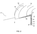
- the bore 3 has a bore surface 3a, as shown in figure 2 , and is surrounded by a recess 4 in the outer surface 2.
- the bore 3 is provided with a bush 5 which is press fitted in the bore 3 and provides an inner surface 7 for rotating engagement with the shaft.
- the bush 5 has a tubular body portion 6 and an annular flange portion 9.
- the body portion 6 is fitted in the bore 3 and provides an inner surface 7 for receiving the shaft and an outer surface 8 which engages the bore surface 3a to hold the bush 5 relative to the component 1.
- the flange portion 9 has a planar lower surface 10 which sits against component 1 within the recess 4.
- the flange portion 9 has an outside edge 12 which extends around and faces away from the body portion 6.
- the flange portion 9 tapers towards its outside edge 12 due to a ramp in its upper surface 11.
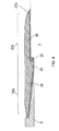
- the seal member 20 has an inner portion 20a which sits above the flange portion 9 of the bush 5 and an outer portion 20b which sits above the outer surface of the component 1, as shown in figure 4 .
- the seal member 20 has an upper surface which faces away from the component 1 and a lower surface which faces towards the component 1 and the bush 5.
- the lower surface of the seal member 20 is shaped to correspond to the contours of the flange 9 and the component 1, and has a ramp providing a taper in the thickness of the seal member towards the centre of the bore which corresponds to the taper in the thickness of the flange portion 9 towards its outside edge 12.
- the lower surface of the seal member 20 also has a step which corresponds to the step provided by the recess 4.
- the lower surface is provided with grooves 21 in its inner and outer portions 20a, 20b which extend annularly around the seal member 20.
- the seal member 20 is made from polyurethane and is flexible, resilient and non-porous.
- a sealant layer 22 of aerospace grade sealant for example aerospace epoxy adhesive under ABP 4-5142 (or another sealant or adhesive material as described above), is disposed between the seal member 20 and the flange portion 9 and between the seal member 20 and the component 1, as shown in figure 3 .
- the sealant layer substantially fills the volume below the seal member 20, and has a thickness of approximately 0.2mm between the flange portion 9 and the seal member and between the outer surface 2 of the component 1 and the seal member for optimised adhesion and sealing performance.
- the sealant layer 22 substantially fills the grooves 21, thereby forming O-ring like protrusions 23 in the sealant layer 22.
- the sealant layer extends slightly beyond the outer edge of the seal member, forming an outer-most portion 22a of the sealant layer which substantially covers the outer edge of the seal member 20.
- the seal member 20 substantially covers the sealant layer 22 so that only a small portion of the sealant layer is exposed to the atmosphere.
- the seal member 20 and the sealant layer 22 form a seal assembly which seals the interface between the flange portion 9 and the component 1.
- the sealant layer 22 also seals the gap between the seal member 20 and the external surface of the component 1.
- the seal assembly reduces the ingress of contaminants including water, oil, dirt and debris between the flange portion 9 and the outer surface of the component 1.
- the seal assembly therefore, reduces contamination of the interface between the outer surface 8 of the body portion 6 and the bore surface 3a due to ingress of contaminants under the flange portion 9. In this way, degradation of the bush 5 and the bore surface 3 over time are reduced, and so the life of the bush assembly is increased.
- the bush 5 is, therefore, less likely to require frequent replacement, and the bore surface 3a of the component 1 is less likely to be degraded to a point at which re-boring of the bore 3 or even replacement of the entire main landing gear component 1 becomes necessary.
- the seal member 20 is non-porous and tougher than the sealant layer 22, and substantially covers the sealant layer, thereby protecting it from exposure to moisture, chemicals and mechanical wear. In this way, the seal member 20 reduces the susceptibility of the sealant layer 22 to damage and degradation during use of the bush assembly, so that the effective life of the sealant layer 22 is increased and the seal assembly is less likely to experience a significant reduction in sealing performance over time.
- the interface between the outer surface 8 of the body portion 6 and the bore surface 3a is, therefore, less likely to become contaminated, and the need for non-destructive tests to assess the performance of the sealant layer is reduced.
- the seal member 20 is less permeable than the sealant layer 22 which it covers, so that the seal assembly provides a more effective barrier against contamination than a layer of sealant alone.
- the advantage becomes increasingly significant as the sealant layer 22 ages because the sealant layer tends to become more porous and brittle over time, for example due to age hardening, but the sealant layer remains substantially covered by the non-porous seal member 20 which substantially prevents the exposure of the sealant layer to contaminants.
- the O-ring like protrusions 23 formed in the sealant layer 22 improve the sealing of the bush assembly against contaminants and provide additional protection against contaminant ingress if part of the sealant layer 22 should tend to lift away from the component 1.
- the O-ring like protrusions 23 also assist with secure location of the seal member 20 on the sealant layer 22.
- the outer-most portion of the sealant layer 22a which covers the outer edge of the seal member 20, seals the edge of the seal member to prevent the ingress of contaminants under the seal member.
- the outer-most portion 22a acts to increase the path length for contaminants entering the seal assembly and provides an additional corner between the seal member 20 and the sealant layer, which any contaminants would need to navigate before reaching the interface between the bush 5 and the bore surface 3a.
- the recess 4 around the bore 3 and the taper provided in the upper surface 11 of the flange portion 9 of the bush 5 allow the extent of the bush assembly protruding outwards from the outer surface 2 of the component 1 to be minimised (i.e. the seal assembly is only just proud of the outer surface) so that the bush assembly is compact and less susceptible to damage.
- the bush and seal member are assembled by pressing the bush 5 into the bore 3 in the component 1; applying a layer of aerospace grade sealant over the flange portion 9 of the bush 5 and the component 1 to form the sealant layer 22; placing the seal member 20 over the bush and component 1; and applying pressure to the bush assembly using a clamping tool 24, as shown in figure 5 .
- the tool comprises an upper part 24a, a lower part 24b and a stud 24c.
- the upper part 24a has a working surface which is adapted to engage the seal member 20, while the lower part 24b engages the surface of the component 1 which faces away from the seal assembly.
- the stud 24c has a threaded end which is received into a threaded recess in the upper part 24a.
- the stud 24c passes through the bore and engages the upper part 24a on one side of the component (the side on which the seal assembly is provided) and the second part 24b on the opposing side of the component.
- the stud 24c is rotated to bring the upper and lower parts 24a and 24b together, thereby applying a clamping force to the seal assembly.
- the upper and lower parts 24a, 24b each have cylindrical surfaces 25a and 25b which engage the inner surface 7 of the body portion 6 of the bush 5 and act as centring means to ensure that the axis of the tool is concentric with the bore 3.
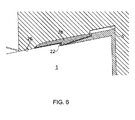
- the working surface extends beyond the outer edge of the seal member 20 to define the extent to which the sealant layer 22 extends beyond the outside edge of the seal member, as shown in figure 6 .
- the tool 24 also comprises a rubber O-ring type seal 26, as shown in Figure 6 , which prevents the sealant layer 22 from leaking outside the tool even when the sealant layer is compressed.
- the tool 24 applies a light clamping force to the seal member 20 which compresses the sealant layer 22.
- the sealant layer is encouraged to conform to the surfaces of the component 1, the flange portion 9 of the bush 5 and the seal member 20, thereby improving the contact between the components of the seal assembly and reducing porosity between the contacting surfaces.
- the tool 24 also helps to ensure correct location of the seal member 20 over the component 1 and the bush 5, and to ensure that the seal member 20 adheres to the sealant layer 22.
- the tool 24 is used to maintain pressure on the seal assembly for at least 4 hours until the sealant layer 22 is at least partially cured.
- the rate at which the sealant cures is dependent on the sealant material used and the conditions in which the sealant layer 22 is allowed to cure. The appropriate time period for which the seal assembly is clamped by the tool 24 therefore depends on the choice of sealant and the curing conditions.
- the seal member 20 and sealant layer 22 are applied to a used bush 5 which is already installed in a main landing gear component 1 of an in service aircraft.
- the seal assembly may, therefore, be applied to an aircraft having a used bush.
- a used bush may be removed from the bore 3 before the replacement bush 5 is fitted in the bore. If the bore surface 3a of the main landing gear component 1 has become degraded, for example due to contamination of the interface between the bore surface 3a and the outer surface 8 of the body portion 6 of the bush 5, a boring tool is used to re-bore the bore 3 to provide a new bore surface into which the bush is fitted. The new bore is at the same location as the original bore and has a greater diameter. The replacement bush 5 therefore has a greater diameter than the used bush which is replaced.
- Figure 7 illustrates a cross section through a bush assembly in accordance with a second embodiment of the invention.
- the bush assembly of Figure 7 is a modified version of that shown in figures 3 and 4 and the same reference numbers followed by a prime (') have been used for identical or equivalent components.
- the sealant layer comprises a first portion 35' of aerospace epoxy adhesive (or another sealant or adhesive material as described above) between the inner portion of the seal member and the flange of the bush 5' and a second portion 36' of aerospace epoxy adhesive (or another sealant or adhesive material as described above) between the outer portion of the seal member and the component 1'.
- the seal member comprises two grooves 21' in its lower surface.
- the bush assembly further comprises a dust shield 32' attached to the flange of the bush 5' which seals against a second component 100' connected by a pin 101' to prevent the ingress of dust and other debris between the first and second components.
- Figure 8 illustrates a cross section through the seal member 20' of figure 7 .
- the seal member is formed of a fluorinated silicone and comprises a reinforcement layer 33' of polyester fabric.
- the seal member 20' further comprises an annular inner contact element 34' at the interface between the inner portion of the seal member and the first portion 35' of the sealant layer and an annular outer contact element 34' at the interface between the outer portion of the seal member and the second portion 36' of the sealant layer.
- the contact elements 34' comprise a glass fibre fabric pre-preg which is co-cured with the main body of the seal member 20'. The contact elements 34' increase the strength of the bond between the seal member 20' and the sealant layer.
- FIG. 9 illustrates a cross section through a bush assembly in accordance with a third embodiment of the invention.
- a seal member 20" includes an integral dust seal portion 200" extending outwardly from the upper surface of the seal member and forming a seal against the second component 100".
- the dust seal portion 200" includes an integral biasing element 201" which acts to bias the dust seal portion towards the second component.
- the seal member may comprise any known non-porous material.
- the bush may have a split down one side or may be provided in multiple segments.
- the seal member may comprise any number of grooves which form O-ring like protrusions in the sealant layer, or no grooves.
- the outside edge 12 of the flange portion 9 may extend up to the outside diameter of the recess 4.
- the component 1 may not comprise a recess surrounding the bore 3, so that the lower surface 10 of the flange portion 9 sits on the outer surface of the component.
- the sealant layer may be applied to the lower surface of the seal member before the seal member is arranged on the main landing gear component.
- the bush assembly may be used in any aircraft or non aircraft application in which a bore in a component is provided with a bush.
Landscapes
- Engineering & Computer Science (AREA)
- General Engineering & Computer Science (AREA)
- Mechanical Engineering (AREA)
- Sealing Devices (AREA)
- Gasket Seals (AREA)
- Sliding-Contact Bearings (AREA)
Description
- The invention relates to a bush assembly; to a kit of parts for forming a bush assembly; to a method for sealing a bush; and to a clamping tool for forming a bush assembly.
- A bush may be fitted in a bore in a component to provide an inner surface within the bore. The inner surface may, for example, provide a bearing surface for receiving a rod or shaft which passes through or into the component. The bush may have a flange which locates the bush within the bore and covers the interface between the bush and the bore surface.
- Over time, the performance of the bush may be reduced, for example due to degradation of the bush and/or the bore surface. Degradation of the interface between the bush and the bore may occur due to contamination, for example by water, oil, dirt or debris, resulting in surface corrosion of the bush and/or bore. The flange may act to reduce contamination of the interface between the bush and the bore, and a layer of sealant may be applied over the bush flange and the surface of the component to seal the bush. However, contamination/corrosion of the bush may still occur, particularly if the layer of sealant becomes damaged or degraded, for example due to mechanical wear, corrosion or age hardening.
- In some cases, it may become necessary to replace the bush, or to re-bore the component and fit a new bush having a larger outside diameter to fit the new bore, or even to replace the component entirely if extensive corrosion has occurred. The problem of contamination of bushes may present a particular problem for large bush assemblies, in which the parts may be difficult and expensive to maintain, monitor and replace. If the component is an aircraft component, for example a main landing gear component, these maintenance tasks may require the aircraft to be removed from service while the maintenance tasks are carried out. Replacing a main landing gear component due to a degraded bush assembly may be time consuming, expensive and wasteful of materials.
-
GB 2359604 - The invention relates to a seal for sealing a bush assembly. The seal includes a seal member which sits over a flange of the bush which is fitted in a bore of a component and a material for sealing between the seal member and the flange/component.
- A first aspect of the invention provides a bush assembly as claimed in
claim 1. - A second aspect of the invention provides a kit of parts for forming a bush assembly as claimed in claim 13.
- A third aspect of the invention provides a method for sealing a bush as claimed in claim 14.
- A fourth aspect of the invention provides a clamping tool for applying a clamping force for sealing a bush installed in a bore in a component as claimed in claim 15.
- The seal assembly may be adapted to substantially prevent the ingress of contaminants into the interface between the flange and the surface of the component, for example to prevent the ingress of water or oil or dirt or debris. The seal assembly may, therefore, reduce or eliminate the ingress of water and/or any other contaminants into the interface between the bush and the surface of the bore.
- By reducing or preventing the ingress of contaminants between the bush and the component, the seal assembly may reduce the rate of degradation of the bush and/or the component, thereby reducing the need for maintenance activities, for example re-boring of the bore and replacement of the bush or replacement of the component.
- The layer of sealant has both adhesive and sealing properties. The layer of sealant may comprise a conventional sealant or aerospace sealant, for example an epoxy sealant or two part epoxy sealant such as aerospace sealant PR-2001 under ABP 4-5142. The aerospace sealant may be used in conjunction with an adhesion promoter. Alternatively (or in addition) the layer of sealant may comprise a conventional adhesive or aerospace adhesive, for example an epoxy adhesive e.g. under AIMS 10-04-002 or a two-part epoxy adhesive.
- The seal member may comprise a solid component which is not an adhesive or sealant type material.
- The seal member may be adapted to substantially cover the layer of sealant, for example the seal member may cover more than 70% of the layer of sealant when viewed in plan view along the axis of the bore. Preferably the seal member covers more than 80% or more than 90% or more than 95% or more than 99% of the area of the layer of sealant.
- The seal member may, therefore, protect the layer of sealant from degradation, for example due to moisture, chemicals and mechanical wear. The seal member may also help to prevent the ingress of contaminants through the layer of sealant, particularly if the seal member is less permeable to contaminants than the layer of sealant or if the properties of the layer of sealant become degraded over time.
- The seal member may be tougher and less permeable than the layer of sealant so that the combined effect of the seal member and the layer of sealant provides a more effective barrier against contamination than a layer of sealant alone.
- The seal member may be substantially annular.
- The annular seal member may be substantially concentric with the bore.
- The annular seal member may be continuous. Alternatively the annular seal member may comprise a split. The split may extend between an inner radial edge and an outer radial edge of the seal member. The split may allow the seal member to be deformed to generate an opening along a split line. Therefore if a pin is located within a bush fitted in a bore of a component, the seal member may be fitted to the bush assembly without removing the pin, for example by opening the split, passing the pin through the slit, and then closing the split so that the seal member radially surrounds the pin. The split may therefore increase ease of installation and removal of the seal assembly. The split may comprise means for improving sealing performance, for example a scarf joint or a lap joint.
- The seal member may comprise a lower surface which faces towards the bush and the component. The lower surface of the seal member may engage the layer of sealant.
- The seal member may comprise an inner portion which overlaps with the flange of the bush, and an outer portion which overlaps with the surface of the component.
- The sealant layer may extend between the inner portion of the seal member and the flange, and between the outer portion of the seal member and the surface of the component.
- The component may comprise a recess in the surface surrounding the bore, which accommodates the flange of the bush. There may be a gap between an outer edge of the flange and an outer edge of the recess. The recess may have a larger diameter than the flange. The seal member may include a step corresponding to an edge of the recess. Alternatively the flange may sit on a nominal outer surface of the component.
- The seal member may include at least one groove formed in the lower surface of the seal member. The groove(s) may be substantially annular. The groove(s) may be filled with the sealant. A groove or plurality of grooves may be provided on the inner portion and/or the outer portion of the seal member. If the flange sits within a recess in the surface of the component surrounding the bore, a groove or a plurality of grooves formed in the outer portion of the seal member may be provided above the recess and/or beyond the outer edge of the recess.
- The layer of sealant may comprise at least one O-ring like portion which engages and at least substantially fills a groove formed in the lower surface of the seal member. The O-ring like portions may improve the sealing of the bush assembly and may provide additional protection against the ingress of contaminants, for example if the layer of sealant has a tendency to lift away from the component. The O-ring like portions may also improve the ability of the layer of sealant to securely locate and retain the seal member and may act as an arrestor in the event of a crack or partial failure of the layer of sealant.
- The seal member may include a non-porous material.
- The seal member may include a plastics material, for example a polyurethane material, or similar. Alternatively the seal member may include an elastomeric material, for example a fluorinated silicone material or another rubber material.
- The seal member may be sufficiently flexible to accommodate deformation of the bush and/or displacement of the bush relative to the component under load, for example load applied to the bush by a pintle pin. Deformation may include the bush assuming an elliptical shape. Displacement may include movement of the bush in an axial direction within the bore and/or rotation of the bush within the bore. The seal assembly may, for example, be able to tolerate the bush moving axially by up to 1mm out of the bore.
- In some embodiments, the seal member may comprise reinforcement. The reinforcement may be provided at or near an upper surface of the seal member facing away from the bush and the component. The reinforcement may be embedded within a main body of the seal member below the upper surface of the seal member. The reinforcement may comprise one or more fabric layers, for example a polyester fabric layer. The reinforcement may increase the durability of the seal and protect the seal member from damage during installation of the seal assembly and/or use of the bush assembly.
- In some embodiments, the seal member may comprise a main body formed of a first material and one or more contact elements formed of a second material which is different to the first material. The contact element(s) may be provided on the lower surface of the seal member at the interface between the seal member and the layer of sealant. The contact elements may comprise a material which provides a more secure bonding surface for the layer of sealant to adhere to than the first material, thereby increasing the strength and durability of the bond between the seal member and the layer of sealant and increasing the life of the seal assembly. The contact elements may, for example, comprise a GFRP or CFRP layer. The contact elements may be co-cured or bonded to the main body of the seal member.
- The flange may have a taper of reducing thickness in the radially outward direction. The seal member may have a complimentary taper.
- The layer of sealant may extend beyond an outer edge of the seal member.
- The layer of sealant may comprise a single continuous layer which extends substantially under the entire seal member. Alternatively there may be a discontinuity in the layer of sealant. For example, the layer of sealant may comprise a first portion of sealant material between the inner portion of the seal member and the flange of the bush and a second portion of sealant material between the outer portion of the seal member and the component. The first and second portions of sealant material may each be substantially annular. There may be a gap between the first and second portions of sealant material. The gap may comprise a void. The void may extend substantially around a radial outer edge of the flange. Alternatively the gap may be filled with another portion of sealant, adhesive or filler. The use of multiple discrete portions of sealant with a gap between the portions may increase the ability of the seal assembly to accommodate deformation and/or displacement of the bush as discussed above. The use of multiple discrete portions of sealant may also help to arrest propagation of a crack in the event of a partial failure of the layer of sealant.
- The seal assembly may comprise multiple contact elements associated with different portions of sealant material. For example the seal assembly may comprise a first contact element via which the first portion of sealant material engages the seal member and a second contact element via which the second portion of sealant material engages the seal member.
- The seal member may comprise an integral dust seal portion extending from an upper surface of the seal member facing away from the bush and component. The dust seal may be adapted to form a seal against a second component which is attached to the component in which the bush is fitted by a pin passing through the bore. The dust seal portion may comprise a reinforcement element or biasing element which acts to bias the dust seal portion towards the second component. The biasing element may for example comprise a metallic or composite rod or strip.
- The component may be an aircraft landing gear component. For example, the component may be a main landing gear component such as a main landing gear forging or a landing gear rib. Alternatively, the component may be any component in an aircraft, or other vehicle, or in any other application.
- The method may further comprise the step of: fitting the bush in the bore before arranging the seal member on the bush. The method may be used to seal a bush which is already fitted in a bore, or may be used to seal a bush which is being newly fitted, or re-fitted, in a bore.
- The method may further comprise the step of: removing an existing bush from the bore before fitting the bush into the bore. The method may, therefore, be used to seal a replacement bush which is replacing a used bush, for example a bush which has become worn or degraded.
- The method may further comprise re-boring the bore before fitting the bush. The original bore may be re-bored to provide a new bore at substantially the same location as the original bore, the new bore having a greater diameter than the original bore. The bush may then be fitted in the new bore.
- The seal assembly may be retro-fitted to an existing bush fitted in a bore of an existing component without modification of the bush or the component.
- The method may further comprise placing a tool on the seal member and applying pressure to the seal member to compress the seal member and the layer of sealant. By compressing the layer of sealant, the tool may encourage the layer of sealant to conform to the component and the flange and the seal member, thereby improving the contact between the components of the bush assembly and reducing porosity between the contacting surfaces, and ensuring correct location of the seal member over the component and the bush. By compressing the layer of sealant, the seal member may also be encouraged to adhere to the layer of sealant.
- The method may further comprise using the tool to maintain pressure on the seal member, thereby compressing the seal member and the layer of sealant, until the layer of sealant is at least partially cured. The seal member may adhere to the layer of sealant when the layer of sealant has cured.
- The first part and/or the second part of the tool may comprise a portion or portions which are adapted to engage a surface of a bore in which the bush is fitted and/or an inner surface of the bush, thereby centring the tool within the bore.
- The centring feature(s) may be circular cylindrical portions of the first and/or second parts of the tool. Alternatively, the centring features may take any other shape capable of centring the tool with respect to the bush and/or the bore by engaging the bore surface and/or the inner surface of the bush.
- The clamping mechanism may pass through the bush. The clamping mechanism may engage the first part of the tool on one side of the component and engage the second part on an opposing side of the component.
- The tool may comprise a seal adapted to prevent sealant from leaking outside a boundary defined by the tool.
- The recess may be adapted to cooperate with a surface of a seal member forming part of the seal. The seal may be a seal as described in relation to the first aspect of the invention.
- The tool may define an extent to which a layer of sealant extends beyond an outside edge of the seal member.
- The tool of the fourth aspect may be used in the method of the third aspect.
- Embodiments of the invention will now be described with reference to the accompanying drawings, in which:
-
Figure 1 illustrates a main landing gear component for an aircraft; -
Figure 2 illustrates a cross section through a main landing gear component with a bush fitted in a bore; -
Figure 3 illustrates a cross section through a bush assembly in accordance with a first embodiment of the invention; -
Figure 4 illustrates a cross section through the seal member used in the bush assembly offigure 3 ; -
Figure 5 illustrates a cross section through a tool being used to assemble the bush assembly offigure 3 ; -
Figure 6 illustrates an enlarged view of the cross section through the tool offigure 5 ; -
Figure 7 illustrates a cross section through a bush assembly in accordance with a second embodiment of the invention; -
Figure 8 illustrates a cross section through the seal member used in the bush assembly offigure 7 ; and -
Figure 9 illustrates a cross section through a bush assembly in accordance with a third embodiment of the invention. - An aircraft (not shown) comprises a landing gear assembly. The landing gear assembly comprises a main
landing gear component 1, a portion of which is shown infigure 1 . Thecomponent 1 has anouter surface 2 and abore 3 extending through the outer surface and continuing through the thickness of the component for receiving a shaft (not shown). Thebore 3 has a bore surface 3a, as shown infigure 2 , and is surrounded by a recess 4 in theouter surface 2. Thebore 3 is provided with abush 5 which is press fitted in thebore 3 and provides an inner surface 7 for rotating engagement with the shaft. - The
bush 5 has atubular body portion 6 and an annular flange portion 9. Thebody portion 6 is fitted in thebore 3 and provides an inner surface 7 for receiving the shaft and anouter surface 8 which engages the bore surface 3a to hold thebush 5 relative to thecomponent 1. The flange portion 9 has a planarlower surface 10 which sits againstcomponent 1 within the recess 4. The flange portion 9 has anoutside edge 12 which extends around and faces away from thebody portion 6. The flange portion 9 tapers towards itsoutside edge 12 due to a ramp in itsupper surface 11. - A
seal member 20, arranged as an annular ring, sits over the flange portion 9 of thebush 5 and the outer surface of thecomponent 1 covering theoutside edge 12 of the flange portion 9, as shown infigure 3 . Theseal member 20 has aninner portion 20a which sits above the flange portion 9 of thebush 5 and anouter portion 20b which sits above the outer surface of thecomponent 1, as shown infigure 4 . Theseal member 20 has an upper surface which faces away from thecomponent 1 and a lower surface which faces towards thecomponent 1 and thebush 5. The lower surface of theseal member 20 is shaped to correspond to the contours of the flange 9 and thecomponent 1, and has a ramp providing a taper in the thickness of the seal member towards the centre of the bore which corresponds to the taper in the thickness of the flange portion 9 towards itsoutside edge 12. The lower surface of theseal member 20 also has a step which corresponds to the step provided by the recess 4. The lower surface is provided withgrooves 21 in its inner andouter portions seal member 20. Theseal member 20 is made from polyurethane and is flexible, resilient and non-porous. - A
sealant layer 22 of aerospace grade sealant, for example aerospace epoxy adhesive under ABP 4-5142 (or another sealant or adhesive material as described above), is disposed between theseal member 20 and the flange portion 9 and between theseal member 20 and thecomponent 1, as shown infigure 3 . The sealant layer substantially fills the volume below theseal member 20, and has a thickness of approximately 0.2mm between the flange portion 9 and the seal member and between theouter surface 2 of thecomponent 1 and the seal member for optimised adhesion and sealing performance. Thesealant layer 22 substantially fills thegrooves 21, thereby forming O-ring likeprotrusions 23 in thesealant layer 22. The sealant layer extends slightly beyond the outer edge of the seal member, forming anouter-most portion 22a of the sealant layer which substantially covers the outer edge of theseal member 20. Theseal member 20 substantially covers thesealant layer 22 so that only a small portion of the sealant layer is exposed to the atmosphere. - The
seal member 20 and thesealant layer 22 form a seal assembly which seals the interface between the flange portion 9 and thecomponent 1. Thesealant layer 22 also seals the gap between theseal member 20 and the external surface of thecomponent 1. The seal assembly reduces the ingress of contaminants including water, oil, dirt and debris between the flange portion 9 and the outer surface of thecomponent 1. The seal assembly, therefore, reduces contamination of the interface between theouter surface 8 of thebody portion 6 and the bore surface 3a due to ingress of contaminants under the flange portion 9. In this way, degradation of thebush 5 and thebore surface 3 over time are reduced, and so the life of the bush assembly is increased. Thebush 5 is, therefore, less likely to require frequent replacement, and the bore surface 3a of thecomponent 1 is less likely to be degraded to a point at which re-boring of thebore 3 or even replacement of the entire mainlanding gear component 1 becomes necessary. Theseal member 20 is non-porous and tougher than thesealant layer 22, and substantially covers the sealant layer, thereby protecting it from exposure to moisture, chemicals and mechanical wear. In this way, theseal member 20 reduces the susceptibility of thesealant layer 22 to damage and degradation during use of the bush assembly, so that the effective life of thesealant layer 22 is increased and the seal assembly is less likely to experience a significant reduction in sealing performance over time. The interface between theouter surface 8 of thebody portion 6 and the bore surface 3a is, therefore, less likely to become contaminated, and the need for non-destructive tests to assess the performance of the sealant layer is reduced. - The
seal member 20 is less permeable than thesealant layer 22 which it covers, so that the seal assembly provides a more effective barrier against contamination than a layer of sealant alone. Theseal member 20, therefore, increases the sealing performance of the seal assembly so that the interface between theouter surface 8 of thebody portion 6 and the bore surface 3a is less likely to become contaminated. The advantage becomes increasingly significant as thesealant layer 22 ages because the sealant layer tends to become more porous and brittle over time, for example due to age hardening, but the sealant layer remains substantially covered by thenon-porous seal member 20 which substantially prevents the exposure of the sealant layer to contaminants. - The O-ring like
protrusions 23 formed in thesealant layer 22 improve the sealing of the bush assembly against contaminants and provide additional protection against contaminant ingress if part of thesealant layer 22 should tend to lift away from thecomponent 1. The O-ring likeprotrusions 23 also assist with secure location of theseal member 20 on thesealant layer 22. - The outer-most portion of the
sealant layer 22a, which covers the outer edge of theseal member 20, seals the edge of the seal member to prevent the ingress of contaminants under the seal member. Theouter-most portion 22a acts to increase the path length for contaminants entering the seal assembly and provides an additional corner between theseal member 20 and the sealant layer, which any contaminants would need to navigate before reaching the interface between thebush 5 and the bore surface 3a. - The recess 4 around the
bore 3 and the taper provided in theupper surface 11 of the flange portion 9 of thebush 5 allow the extent of the bush assembly protruding outwards from theouter surface 2 of thecomponent 1 to be minimised (i.e. the seal assembly is only just proud of the outer surface) so that the bush assembly is compact and less susceptible to damage. - The bush and seal member are assembled by pressing the
bush 5 into thebore 3 in thecomponent 1; applying a layer of aerospace grade sealant over the flange portion 9 of thebush 5 and thecomponent 1 to form thesealant layer 22; placing theseal member 20 over the bush andcomponent 1; and applying pressure to the bush assembly using aclamping tool 24, as shown infigure 5 . - The tool comprises an
upper part 24a, alower part 24b and astud 24c. Theupper part 24a has a working surface which is adapted to engage theseal member 20, while thelower part 24b engages the surface of thecomponent 1 which faces away from the seal assembly. Thestud 24c has a threaded end which is received into a threaded recess in theupper part 24a. Thestud 24c passes through the bore and engages theupper part 24a on one side of the component (the side on which the seal assembly is provided) and thesecond part 24b on the opposing side of the component. Thestud 24c is rotated to bring the upper andlower parts lower parts cylindrical surfaces body portion 6 of thebush 5 and act as centring means to ensure that the axis of the tool is concentric with thebore 3. - The working surface extends beyond the outer edge of the
seal member 20 to define the extent to which thesealant layer 22 extends beyond the outside edge of the seal member, as shown infigure 6 . Thetool 24 also comprises a rubber O-ring type seal 26, as shown inFigure 6 , which prevents thesealant layer 22 from leaking outside the tool even when the sealant layer is compressed. - The
tool 24 applies a light clamping force to theseal member 20 which compresses thesealant layer 22. By compressing thesealant layer 22 beneath theseal member 20, the sealant layer is encouraged to conform to the surfaces of thecomponent 1, the flange portion 9 of thebush 5 and theseal member 20, thereby improving the contact between the components of the seal assembly and reducing porosity between the contacting surfaces. Thetool 24 also helps to ensure correct location of theseal member 20 over thecomponent 1 and thebush 5, and to ensure that theseal member 20 adheres to thesealant layer 22. Thetool 24 is used to maintain pressure on the seal assembly for at least 4 hours until thesealant layer 22 is at least partially cured. The rate at which the sealant cures is dependent on the sealant material used and the conditions in which thesealant layer 22 is allowed to cure. The appropriate time period for which the seal assembly is clamped by thetool 24 therefore depends on the choice of sealant and the curing conditions. - In an alternative embodiment, the
seal member 20 andsealant layer 22 are applied to a usedbush 5 which is already installed in a mainlanding gear component 1 of an in service aircraft. The seal assembly may, therefore, be applied to an aircraft having a used bush. Alternatively, when the seal assembly is installed on an in service aircraft, a used bush may be removed from thebore 3 before thereplacement bush 5 is fitted in the bore. If the bore surface 3a of the mainlanding gear component 1 has become degraded, for example due to contamination of the interface between the bore surface 3a and theouter surface 8 of thebody portion 6 of thebush 5, a boring tool is used to re-bore thebore 3 to provide a new bore surface into which the bush is fitted. The new bore is at the same location as the original bore and has a greater diameter. Thereplacement bush 5 therefore has a greater diameter than the used bush which is replaced. -
Figure 7 illustrates a cross section through a bush assembly in accordance with a second embodiment of the invention. The bush assembly ofFigure 7 is a modified version of that shown infigures 3 and4 and the same reference numbers followed by a prime (') have been used for identical or equivalent components. The sealant layer comprises a first portion 35' of aerospace epoxy adhesive (or another sealant or adhesive material as described above) between the inner portion of the seal member and the flange of the bush 5' and a second portion 36' of aerospace epoxy adhesive (or another sealant or adhesive material as described above) between the outer portion of the seal member and the component 1'. There is a gap 31' between the first and second portions of sealant material. The seal member comprises two grooves 21' in its lower surface. Both grooves are formed in the outer portion of the seal member such that two O-ring like protrusions 23' are formed in the second portion of epoxy adhesive 36' between the seal member and the component 1'. The bush assembly further comprises a dust shield 32' attached to the flange of the bush 5' which seals against a second component 100' connected by a pin 101' to prevent the ingress of dust and other debris between the first and second components. -
Figure 8 illustrates a cross section through the seal member 20' offigure 7 . The seal member is formed of a fluorinated silicone and comprises a reinforcement layer 33' of polyester fabric. The seal member 20' further comprises an annular inner contact element 34' at the interface between the inner portion of the seal member and the first portion 35' of the sealant layer and an annular outer contact element 34' at the interface between the outer portion of the seal member and the second portion 36' of the sealant layer. The contact elements 34' comprise a glass fibre fabric pre-preg which is co-cured with the main body of the seal member 20'. The contact elements 34' increase the strength of the bond between the seal member 20' and the sealant layer. -
Figure 9 illustrates a cross section through a bush assembly in accordance with a third embodiment of the invention. The same reference numbers followed by a double prime (") have been used for identical or equivalent components. In the bush assembly ofFigure 9 aseal member 20" includes an integraldust seal portion 200" extending outwardly from the upper surface of the seal member and forming a seal against thesecond component 100". Thedust seal portion 200" includes anintegral biasing element 201" which acts to bias the dust seal portion towards the second component. - In an alternative embodiment, the seal member may comprise any known non-porous material.
- In an alternative embodiment, the bush may have a split down one side or may be provided in multiple segments.
- In an alternative embodiment, the seal member may comprise any number of grooves which form O-ring like protrusions in the sealant layer, or no grooves.
- In an alternative embodiment, the
outside edge 12 of the flange portion 9 may extend up to the outside diameter of the recess 4. - In an alternative embodiment, the
component 1 may not comprise a recess surrounding thebore 3, so that thelower surface 10 of the flange portion 9 sits on the outer surface of the component. - In an alternative embodiment, the sealant layer may be applied to the lower surface of the seal member before the seal member is arranged on the main landing gear component.
- In an alternative embodiment, the bush assembly may be used in any aircraft or non aircraft application in which a bore in a component is provided with a bush.
- Although the invention has been described above with reference to one or more preferred embodiments, it will be appreciated that various changes or modifications may be made without departing from the scope of the invention as defined in the appended claims. In particular, one or all of the features of any one of the embodiments may be combined with any of the features of any other embodiment or with a bush assembly or method according to the appended claims.
Claims (15)
- A bush assembly comprising a component (1) having a bore (3), a bush (5) fitted in the bore and having a flange (9) that extends radially outwardly over a surface of the component surrounding the bore, and a seal assembly for sealing the interface between the flange and the surface of the component, characterised in that the seal assembly includes a seal member (20) and a layer of sealant (22) between the seal member and the interface between the flange and the surface of the component.
- A bush assembly according to claim 1, wherein the sealant layer seals the gap between the seal member and the external surface of the component and thereby substantially prevents the ingress of contaminants into the interface between the flange (9) and the surface of the component (1).
- A bush assembly according to any preceding claim, wherein the seal member is substantially annular.
- A bush assembly according to any preceding claim, wherein the seal member includes an inner portion (20a) which overlaps with the flange of the bush, and an outer portion which overlaps with the surface of the component.
- A bush assembly according to claim 4, wherein the sealant layer extends between the inner portion of the seal member and the flange, and between the outer portion (20b) of the seal member and the surface of the component.
- A bush assembly according to claim 5, wherein the layer of sealant comprises a first portion of sealant material between the inner portion of the seal member and the flange of the bush and a second portion of sealant material between the outer portion of the seal member and the component, and wherein there is a gap between the first and second portions of sealant material.
- A bush assembly according to claim 6, wherein the gap comprises a void extending substantially around a radial outer edge of the flange.
- A bush assembly according to any preceding claim, wherein the seal member includes at least one groove (21) formed in a lower surface of the seal member, which is filled with the sealant.
- A bush assembly according to any preceding claim, wherein the seal member includes a plastics material or an elastomeric material.
- A bush assembly according to any preceding claim, wherein the seal member comprises a main body formed of a first material and one or more contact elements formed of a second material which is different to the first material, each contact element being provided at the interface between the seal member and the layer of sealant.
- A bush assembly according to any preceding claim, wherein the layer of sealant extends beyond an outer edge of the seal member.
- A bush assembly according to any preceding claim, wherein the component is an aircraft landing gear component, preferably a main landing gear forging or landing gear rib.
- A kit of parts for forming a bush assembly, the kit of parts comprising a bush (5) for fitting in a bore in a component, a seal member (20) and a sealant material; wherein the bush has a flange (9) that is adapted to extend radially outwardly over a surface of the component surrounding the bore when the bush is fitted in the bore; and characterised in that the sealant material is for providing a layer of sealant between the seal member and an interface between the flange (9) and the surface of the component such that the layer of sealant and the seal member form a seal assembly for sealing the interface between the flange and the surface of the component.
- A method for sealing a bush, the method comprising the steps of: providing a component (1) having a bore (3) with a bush (5) fitted in the bore, the bush having a flange (9) that extends radially outwardly over a surface of the component surrounding the bore; arranging a seal member (20) with respect to the bush; characterised by introducing a sealant material so as to provide a layer of the sealant material between the seal member and an interface between the flange and the surface of the component to form a seal assembly for sealing the interface between the flange and the surface of the component.
- A clamping tool (24) for applying a clamping force for sealing a bush assembly according to any of preceding claims 1-12 installed in a bore in a component, the tool comprising a first part (24a), a second part (24b) and a clamping mechanism (24c); characterised in that the first part comprises a recess which is adapted to engage a seal; the second part is adapted to engage a surface of the component which opposes and faces away from a surface of the component on which the seal is provided; the clamping mechanism is operable to move the first part relative to the second part, thereby applying a clamping force to the seal; and wherein the clamping tool includes centring means for centring the clamping tool relative to the bush.
Applications Claiming Priority (2)
| Application Number | Priority Date | Filing Date | Title |
|---|---|---|---|
| GBGB1207511.5A GB201207511D0 (en) | 2012-04-30 | 2012-04-30 | Bush assembly |
| PCT/GB2013/051052 WO2013164580A1 (en) | 2012-04-30 | 2013-04-25 | Bush assembly |
Publications (2)
| Publication Number | Publication Date |
|---|---|
| EP2844883A1 EP2844883A1 (en) | 2015-03-11 |
| EP2844883B1 true EP2844883B1 (en) | 2016-11-09 |
Family
ID=46330544
Family Applications (1)
| Application Number | Title | Priority Date | Filing Date |
|---|---|---|---|
| EP13719154.0A Active EP2844883B1 (en) | 2012-04-30 | 2013-04-25 | Bush assembly |
Country Status (7)
| Country | Link |
|---|---|
| US (2) | US9303693B2 (en) |
| EP (1) | EP2844883B1 (en) |
| JP (1) | JP2015517075A (en) |
| CN (1) | CN104411985B (en) |
| CA (1) | CA2872197A1 (en) |
| GB (1) | GB201207511D0 (en) |
| WO (1) | WO2013164580A1 (en) |
Families Citing this family (6)
| Publication number | Priority date | Publication date | Assignee | Title |
|---|---|---|---|---|
| EP3059163B1 (en) | 2015-02-18 | 2019-06-19 | Safran Landing Systems UK Limited | Aircraft assembly |
| JP6466203B2 (en) * | 2015-02-26 | 2019-02-06 | Jfeスチール株式会社 | How to repair roll chock for rolling mill |
| GB2536471A (en) | 2015-03-18 | 2016-09-21 | Airbus Operations Ltd | Self-sealing fixing element |
| EP3544122B1 (en) * | 2018-03-21 | 2022-10-26 | TE Connectivity Germany GmbH | Connection assembly with a thin conductor piece to a thick conductor piece connected to each other, and method for connecting said conductor pieces |
| FR3119003B1 (en) * | 2021-01-21 | 2023-04-28 | Stelia Aerospace | Method and system for sealingly joining an auxiliary through part to a main part |
| CN114986921B (en) * | 2022-05-31 | 2023-11-07 | 宁波曙翔新材料股份有限公司 | Stepped hole for sandwich composite material and preparation method thereof |
Family Cites Families (28)
| Publication number | Priority date | Publication date | Assignee | Title |
|---|---|---|---|---|
| US889315A (en) * | 1907-05-31 | 1908-06-02 | James B Etherington | Apparatus for coupling pipes. |
| GB310685A (en) * | 1928-05-26 | 1929-05-02 | Archibald Smith Briggs | Improvements in packing washers or grummets and joints made therewith |
| GB513976A (en) * | 1938-08-09 | 1939-10-26 | Glenn L Martin Co | Methods of forming a sealed connection between two structural members |
| US2957717A (en) * | 1957-03-13 | 1960-10-25 | Cie De Pont A Mousson | Sealing members and reinforcements therefor |
| GB1527213A (en) * | 1977-05-11 | 1978-10-04 | Essex Partners Ltd | Fittings |
| US4310933A (en) * | 1979-07-06 | 1982-01-19 | Tappan Company | Food waste disposer mounting assembly |
| US4372015A (en) * | 1981-05-13 | 1983-02-08 | The Boeing Company | Blind hole clamping tool |
| US4601614A (en) * | 1984-02-22 | 1986-07-22 | Lane William L | Rockbolt |
| US4805505A (en) * | 1988-03-02 | 1989-02-21 | John Cantlin | Multi-stop |
| SE462554B (en) * | 1989-02-01 | 1990-07-16 | Sandvik Ab | SPINDLE DEVICE FOR TOOL |
| JPH02132123U (en) * | 1989-04-07 | 1990-11-02 | ||
| JPH0425612A (en) * | 1990-05-22 | 1992-01-29 | Iseki & Co Ltd | plain bearing |
| JPH0810702Y2 (en) | 1990-11-06 | 1996-03-29 | 旭電化工業株式会社 | Washer with water-swellable rubber |
| US5418983A (en) * | 1994-06-01 | 1995-05-30 | Jameco Industries, Inc. | Decorative color changeable basket sink strainer |
| DE4429102A1 (en) * | 1994-08-17 | 1996-02-22 | Lemfoerder Metallwaren Ag | Radially and axially loadable bush bearing for chassis parts in motor vehicles |
| US5709018A (en) * | 1995-04-28 | 1998-01-20 | Dugan; Charles E. | Seal manipulation tools |
| US5730446A (en) * | 1995-06-20 | 1998-03-24 | Minnesota Mining And Manufacturing Company | Sealing strip suitable for sealing a hem flange |
| US5887913A (en) * | 1995-11-21 | 1999-03-30 | Noriatsu Kojima | Pipe joint structure |
| US5745931A (en) * | 1996-02-09 | 1998-05-05 | Wcm Industries, Inc. | Method and means for covering the flange of a waste water strainer |
| US5893202A (en) * | 1997-09-19 | 1999-04-13 | Chiquita Brands, Inc. | Tool and method for installing the inner oil seal in the hub of a wheel assembly |
| US6065198A (en) * | 1998-12-02 | 2000-05-23 | Daimlerchrysler Corporation | Tools for installing an oil seal |
| GB2359604A (en) * | 2000-02-25 | 2001-08-29 | Fokker Aerostructures Bv | A method for producing a liquid-tight joint for an aircraft fuel tank |
| US6775890B2 (en) * | 2000-09-25 | 2004-08-17 | Frank Kolarik | Apparatus for urging two members apart or together |
| US6792658B2 (en) * | 2002-07-24 | 2004-09-21 | Thomas D. Capoferi | Valve seal removal apparatus |
| GB2392711B (en) * | 2002-09-03 | 2004-08-18 | Auto Service Tools Ltd | Holding device |
| US6979027B2 (en) * | 2003-05-07 | 2005-12-27 | Watts Regulator Co. | Toilet carrier |
| US7389579B2 (en) * | 2006-02-15 | 2008-06-24 | Rode John E | Apparatus for providing a load on a bearing, the bearing having an inner race mounted to a shaft and the bearing retained by a nut |
| US7966911B2 (en) * | 2005-09-15 | 2011-06-28 | Lisle Corporation | Hose clamp removal and installation tool |
-
2012
- 2012-04-30 GB GBGB1207511.5A patent/GB201207511D0/en not_active Ceased
-
2013
- 2013-04-25 US US14/397,699 patent/US9303693B2/en active Active
- 2013-04-25 CN CN201380035130.2A patent/CN104411985B/en not_active Expired - Fee Related
- 2013-04-25 WO PCT/GB2013/051052 patent/WO2013164580A1/en not_active Ceased
- 2013-04-25 EP EP13719154.0A patent/EP2844883B1/en active Active
- 2013-04-25 JP JP2015509485A patent/JP2015517075A/en active Pending
- 2013-04-25 CA CA2872197A patent/CA2872197A1/en not_active Abandoned
-
2016
- 2016-02-01 US US15/012,202 patent/US20160144493A1/en not_active Abandoned
Also Published As
| Publication number | Publication date |
|---|---|
| JP2015517075A (en) | 2015-06-18 |
| CN104411985A (en) | 2015-03-11 |
| WO2013164580A1 (en) | 2013-11-07 |
| US20150086143A1 (en) | 2015-03-26 |
| EP2844883A1 (en) | 2015-03-11 |
| US9303693B2 (en) | 2016-04-05 |
| CA2872197A1 (en) | 2013-11-07 |
| US20160144493A1 (en) | 2016-05-26 |
| CN104411985B (en) | 2016-02-24 |
| GB201207511D0 (en) | 2012-06-13 |
Similar Documents
| Publication | Publication Date | Title |
|---|---|---|
| US20160144493A1 (en) | Bush assembly | |
| US8196523B2 (en) | Railroad tanker car manway cover seal | |
| US10746302B2 (en) | Seal and corresponding manufacturing method | |
| WO2005010410A2 (en) | Composite seal and window assembly | |
| US4986553A (en) | Shaft seal | |
| US8210543B2 (en) | Seal for a bushing | |
| EP2705284B1 (en) | Hydrodynamic seal with increased flexibility sealing element | |
| US4818620A (en) | Elastomer coated lip seal | |
| KR20200079262A (en) | Sealing device for jointing two joint elements of offshore structures and method for manufacturing same | |
| US9540780B2 (en) | Pot bearing | |
| US20020158421A1 (en) | Shaft seal having a hinge and a liner | |
| CN101438084A (en) | Robust sealing system for power steering input shaft | |
| US20120324707A1 (en) | Pivot joint assembly | |
| RU2518789C2 (en) | Support ring of railway bearing | |
| EP2074336A2 (en) | Vehicle with elastomeric bearing suspension system and elastomeric bearing therefor | |
| US7080807B2 (en) | Window frame/seal assembly and method of forming the same | |
| CN121516219A (en) | Asymmetrically connected acrylic laminate windshield | |
| US20100025950A1 (en) | Ball joint, preferably for use in vehicles | |
| EP0104753B1 (en) | Joint with face seal assembly | |
| US9493198B2 (en) | Sealing assembly and hinge of a track having the sealing assembly | |
| EP2115312B1 (en) | Clutch release bearing device | |
| WO2008118236A2 (en) | Pitch bearing containment seal | |
| CA2438258C (en) | Articulated seal | |
| CN212429538U (en) | Positioning structure of metal sealing ring | |
| US20160009324A1 (en) | Track bushing for endless track |
Legal Events
| Date | Code | Title | Description |
|---|---|---|---|
| PUAI | Public reference made under article 153(3) epc to a published international application that has entered the european phase |
Free format text: ORIGINAL CODE: 0009012 |
|
| 17P | Request for examination filed |
Effective date: 20141030 |
|
| AK | Designated contracting states |
Kind code of ref document: A1 Designated state(s): AL AT BE BG CH CY CZ DE DK EE ES FI FR GB GR HR HU IE IS IT LI LT LU LV MC MK MT NL NO PL PT RO RS SE SI SK SM TR |
|
| AX | Request for extension of the european patent |
Extension state: BA ME |
|
| DAX | Request for extension of the european patent (deleted) | ||
| GRAP | Despatch of communication of intention to grant a patent |
Free format text: ORIGINAL CODE: EPIDOSNIGR1 |
|
| INTG | Intention to grant announced |
Effective date: 20160621 |
|
| GRAS | Grant fee paid |
Free format text: ORIGINAL CODE: EPIDOSNIGR3 |
|
| GRAA | (expected) grant |
Free format text: ORIGINAL CODE: 0009210 |
|
| AK | Designated contracting states |
Kind code of ref document: B1 Designated state(s): AL AT BE BG CH CY CZ DE DK EE ES FI FR GB GR HR HU IE IS IT LI LT LU LV MC MK MT NL NO PL PT RO RS SE SI SK SM TR |
|
| REG | Reference to a national code |
Ref country code: GB Ref legal event code: FG4D |
|
| REG | Reference to a national code |
Ref country code: AT Ref legal event code: REF Ref document number: 844216 Country of ref document: AT Kind code of ref document: T Effective date: 20161115 Ref country code: CH Ref legal event code: EP |
|
| REG | Reference to a national code |
Ref country code: IE Ref legal event code: FG4D |
|
| REG | Reference to a national code |
Ref country code: DE Ref legal event code: R096 Ref document number: 602013013798 Country of ref document: DE |
|
| PG25 | Lapsed in a contracting state [announced via postgrant information from national office to epo] |
Ref country code: LV Free format text: LAPSE BECAUSE OF FAILURE TO SUBMIT A TRANSLATION OF THE DESCRIPTION OR TO PAY THE FEE WITHIN THE PRESCRIBED TIME-LIMIT Effective date: 20161109 |
|
| REG | Reference to a national code |
Ref country code: LT Ref legal event code: MG4D |
|
| REG | Reference to a national code |
Ref country code: NL Ref legal event code: MP Effective date: 20161109 |
|
| REG | Reference to a national code |
Ref country code: AT Ref legal event code: MK05 Ref document number: 844216 Country of ref document: AT Kind code of ref document: T Effective date: 20161109 |
|
| REG | Reference to a national code |
Ref country code: FR Ref legal event code: PLFP Year of fee payment: 5 |
|
| PG25 | Lapsed in a contracting state [announced via postgrant information from national office to epo] |
Ref country code: LT Free format text: LAPSE BECAUSE OF FAILURE TO SUBMIT A TRANSLATION OF THE DESCRIPTION OR TO PAY THE FEE WITHIN THE PRESCRIBED TIME-LIMIT Effective date: 20161109 Ref country code: NO Free format text: LAPSE BECAUSE OF FAILURE TO SUBMIT A TRANSLATION OF THE DESCRIPTION OR TO PAY THE FEE WITHIN THE PRESCRIBED TIME-LIMIT Effective date: 20170209 Ref country code: NL Free format text: LAPSE BECAUSE OF FAILURE TO SUBMIT A TRANSLATION OF THE DESCRIPTION OR TO PAY THE FEE WITHIN THE PRESCRIBED TIME-LIMIT Effective date: 20161109 Ref country code: SE Free format text: LAPSE BECAUSE OF FAILURE TO SUBMIT A TRANSLATION OF THE DESCRIPTION OR TO PAY THE FEE WITHIN THE PRESCRIBED TIME-LIMIT Effective date: 20161109 Ref country code: GR Free format text: LAPSE BECAUSE OF FAILURE TO SUBMIT A TRANSLATION OF THE DESCRIPTION OR TO PAY THE FEE WITHIN THE PRESCRIBED TIME-LIMIT Effective date: 20170210 |
|
| PG25 | Lapsed in a contracting state [announced via postgrant information from national office to epo] |
Ref country code: AT Free format text: LAPSE BECAUSE OF FAILURE TO SUBMIT A TRANSLATION OF THE DESCRIPTION OR TO PAY THE FEE WITHIN THE PRESCRIBED TIME-LIMIT Effective date: 20161109 Ref country code: PT Free format text: LAPSE BECAUSE OF FAILURE TO SUBMIT A TRANSLATION OF THE DESCRIPTION OR TO PAY THE FEE WITHIN THE PRESCRIBED TIME-LIMIT Effective date: 20170309 Ref country code: RS Free format text: LAPSE BECAUSE OF FAILURE TO SUBMIT A TRANSLATION OF THE DESCRIPTION OR TO PAY THE FEE WITHIN THE PRESCRIBED TIME-LIMIT Effective date: 20161109 Ref country code: FI Free format text: LAPSE BECAUSE OF FAILURE TO SUBMIT A TRANSLATION OF THE DESCRIPTION OR TO PAY THE FEE WITHIN THE PRESCRIBED TIME-LIMIT Effective date: 20161109 Ref country code: HR Free format text: LAPSE BECAUSE OF FAILURE TO SUBMIT A TRANSLATION OF THE DESCRIPTION OR TO PAY THE FEE WITHIN THE PRESCRIBED TIME-LIMIT Effective date: 20161109 Ref country code: IS Free format text: LAPSE BECAUSE OF FAILURE TO SUBMIT A TRANSLATION OF THE DESCRIPTION OR TO PAY THE FEE WITHIN THE PRESCRIBED TIME-LIMIT Effective date: 20170309 Ref country code: PL Free format text: LAPSE BECAUSE OF FAILURE TO SUBMIT A TRANSLATION OF THE DESCRIPTION OR TO PAY THE FEE WITHIN THE PRESCRIBED TIME-LIMIT Effective date: 20161109 Ref country code: ES Free format text: LAPSE BECAUSE OF FAILURE TO SUBMIT A TRANSLATION OF THE DESCRIPTION OR TO PAY THE FEE WITHIN THE PRESCRIBED TIME-LIMIT Effective date: 20161109 |
|
| PG25 | Lapsed in a contracting state [announced via postgrant information from national office to epo] |
Ref country code: EE Free format text: LAPSE BECAUSE OF FAILURE TO SUBMIT A TRANSLATION OF THE DESCRIPTION OR TO PAY THE FEE WITHIN THE PRESCRIBED TIME-LIMIT Effective date: 20161109 Ref country code: CZ Free format text: LAPSE BECAUSE OF FAILURE TO SUBMIT A TRANSLATION OF THE DESCRIPTION OR TO PAY THE FEE WITHIN THE PRESCRIBED TIME-LIMIT Effective date: 20161109 Ref country code: RO Free format text: LAPSE BECAUSE OF FAILURE TO SUBMIT A TRANSLATION OF THE DESCRIPTION OR TO PAY THE FEE WITHIN THE PRESCRIBED TIME-LIMIT Effective date: 20161109 Ref country code: DK Free format text: LAPSE BECAUSE OF FAILURE TO SUBMIT A TRANSLATION OF THE DESCRIPTION OR TO PAY THE FEE WITHIN THE PRESCRIBED TIME-LIMIT Effective date: 20161109 Ref country code: SK Free format text: LAPSE BECAUSE OF FAILURE TO SUBMIT A TRANSLATION OF THE DESCRIPTION OR TO PAY THE FEE WITHIN THE PRESCRIBED TIME-LIMIT Effective date: 20161109 |
|
| REG | Reference to a national code |
Ref country code: DE Ref legal event code: R097 Ref document number: 602013013798 Country of ref document: DE |
|
| PG25 | Lapsed in a contracting state [announced via postgrant information from national office to epo] |
Ref country code: BG Free format text: LAPSE BECAUSE OF FAILURE TO SUBMIT A TRANSLATION OF THE DESCRIPTION OR TO PAY THE FEE WITHIN THE PRESCRIBED TIME-LIMIT Effective date: 20170209 Ref country code: SM Free format text: LAPSE BECAUSE OF FAILURE TO SUBMIT A TRANSLATION OF THE DESCRIPTION OR TO PAY THE FEE WITHIN THE PRESCRIBED TIME-LIMIT Effective date: 20161109 Ref country code: IT Free format text: LAPSE BECAUSE OF FAILURE TO SUBMIT A TRANSLATION OF THE DESCRIPTION OR TO PAY THE FEE WITHIN THE PRESCRIBED TIME-LIMIT Effective date: 20161109 Ref country code: BE Free format text: LAPSE BECAUSE OF FAILURE TO SUBMIT A TRANSLATION OF THE DESCRIPTION OR TO PAY THE FEE WITHIN THE PRESCRIBED TIME-LIMIT Effective date: 20161109 |
|
| PLBE | No opposition filed within time limit |
Free format text: ORIGINAL CODE: 0009261 |
|
| STAA | Information on the status of an ep patent application or granted ep patent |
Free format text: STATUS: NO OPPOSITION FILED WITHIN TIME LIMIT |
|
| 26N | No opposition filed |
Effective date: 20170810 |
|
| PG25 | Lapsed in a contracting state [announced via postgrant information from national office to epo] |
Ref country code: SI Free format text: LAPSE BECAUSE OF FAILURE TO SUBMIT A TRANSLATION OF THE DESCRIPTION OR TO PAY THE FEE WITHIN THE PRESCRIBED TIME-LIMIT Effective date: 20161109 |
|
| REG | Reference to a national code |
Ref country code: CH Ref legal event code: PL |
|
| REG | Reference to a national code |
Ref country code: IE Ref legal event code: MM4A |
|
| PG25 | Lapsed in a contracting state [announced via postgrant information from national office to epo] |
Ref country code: MC Free format text: LAPSE BECAUSE OF FAILURE TO SUBMIT A TRANSLATION OF THE DESCRIPTION OR TO PAY THE FEE WITHIN THE PRESCRIBED TIME-LIMIT Effective date: 20161109 |
|
| PG25 | Lapsed in a contracting state [announced via postgrant information from national office to epo] |
Ref country code: LI Free format text: LAPSE BECAUSE OF NON-PAYMENT OF DUE FEES Effective date: 20170430 Ref country code: LU Free format text: LAPSE BECAUSE OF NON-PAYMENT OF DUE FEES Effective date: 20170425 Ref country code: CH Free format text: LAPSE BECAUSE OF NON-PAYMENT OF DUE FEES Effective date: 20170430 |
|
| REG | Reference to a national code |
Ref country code: FR Ref legal event code: PLFP Year of fee payment: 6 |
|
| PG25 | Lapsed in a contracting state [announced via postgrant information from national office to epo] |
Ref country code: IE Free format text: LAPSE BECAUSE OF NON-PAYMENT OF DUE FEES Effective date: 20170425 |
|
| PG25 | Lapsed in a contracting state [announced via postgrant information from national office to epo] |
Ref country code: MT Free format text: LAPSE BECAUSE OF NON-PAYMENT OF DUE FEES Effective date: 20170425 |
|
| PG25 | Lapsed in a contracting state [announced via postgrant information from national office to epo] |
Ref country code: HU Free format text: LAPSE BECAUSE OF FAILURE TO SUBMIT A TRANSLATION OF THE DESCRIPTION OR TO PAY THE FEE WITHIN THE PRESCRIBED TIME-LIMIT; INVALID AB INITIO Effective date: 20130425 |
|
| PG25 | Lapsed in a contracting state [announced via postgrant information from national office to epo] |
Ref country code: CY Free format text: LAPSE BECAUSE OF FAILURE TO SUBMIT A TRANSLATION OF THE DESCRIPTION OR TO PAY THE FEE WITHIN THE PRESCRIBED TIME-LIMIT Effective date: 20161109 |
|
| PG25 | Lapsed in a contracting state [announced via postgrant information from national office to epo] |
Ref country code: MK Free format text: LAPSE BECAUSE OF FAILURE TO SUBMIT A TRANSLATION OF THE DESCRIPTION OR TO PAY THE FEE WITHIN THE PRESCRIBED TIME-LIMIT Effective date: 20161109 |
|
| PG25 | Lapsed in a contracting state [announced via postgrant information from national office to epo] |
Ref country code: TR Free format text: LAPSE BECAUSE OF FAILURE TO SUBMIT A TRANSLATION OF THE DESCRIPTION OR TO PAY THE FEE WITHIN THE PRESCRIBED TIME-LIMIT Effective date: 20161109 |
|
| PG25 | Lapsed in a contracting state [announced via postgrant information from national office to epo] |
Ref country code: AL Free format text: LAPSE BECAUSE OF FAILURE TO SUBMIT A TRANSLATION OF THE DESCRIPTION OR TO PAY THE FEE WITHIN THE PRESCRIBED TIME-LIMIT Effective date: 20161109 |
|
| PGFP | Annual fee paid to national office [announced via postgrant information from national office to epo] |
Ref country code: DE Payment date: 20250422 Year of fee payment: 13 |
|
| PGFP | Annual fee paid to national office [announced via postgrant information from national office to epo] |
Ref country code: GB Payment date: 20250423 Year of fee payment: 13 |
|
| PGFP | Annual fee paid to national office [announced via postgrant information from national office to epo] |
Ref country code: FR Payment date: 20250425 Year of fee payment: 13 |