EP2844058B1 - Hangable container - Google Patents
Hangable container Download PDFInfo
- Publication number
- EP2844058B1 EP2844058B1 EP13721119.9A EP13721119A EP2844058B1 EP 2844058 B1 EP2844058 B1 EP 2844058B1 EP 13721119 A EP13721119 A EP 13721119A EP 2844058 B1 EP2844058 B1 EP 2844058B1
- Authority
- EP
- European Patent Office
- Prior art keywords
- container
- catch
- stem
- flower
- shell
- Prior art date
- Legal status (The legal status is an assumption and is not a legal conclusion. Google has not performed a legal analysis and makes no representation as to the accuracy of the status listed.)
- Not-in-force
Links
- 244000273618 Sphenoclea zeylanica Species 0.000 claims description 26
- 238000006073 displacement reaction Methods 0.000 claims description 2
- 238000001746 injection moulding Methods 0.000 claims description 2
- 241000196324 Embryophyta Species 0.000 description 4
- 230000005484 gravity Effects 0.000 description 3
- 239000012530 fluid Substances 0.000 description 2
- 239000002689 soil Substances 0.000 description 2
- 238000004873 anchoring Methods 0.000 description 1
- 230000002262 irrigation Effects 0.000 description 1
- 238000003973 irrigation Methods 0.000 description 1
- 238000012986 modification Methods 0.000 description 1
- 230000004048 modification Effects 0.000 description 1
- 239000000758 substrate Substances 0.000 description 1
- 239000000725 suspension Substances 0.000 description 1
Images





Classifications
-
- A—HUMAN NECESSITIES
- A01—AGRICULTURE; FORESTRY; ANIMAL HUSBANDRY; HUNTING; TRAPPING; FISHING
- A01G—HORTICULTURE; CULTIVATION OF VEGETABLES, FLOWERS, RICE, FRUIT, VINES, HOPS OR SEAWEED; FORESTRY; WATERING
- A01G9/00—Cultivation in receptacles, forcing-frames or greenhouses; Edging for beds, lawn or the like
- A01G9/02—Receptacles, e.g. flower-pots or boxes; Glasses for cultivating flowers
- A01G9/022—Pots for vertical horticulture
- A01G9/024—Hanging flower pots and baskets
-
- A—HUMAN NECESSITIES
- A01—AGRICULTURE; FORESTRY; ANIMAL HUSBANDRY; HUNTING; TRAPPING; FISHING
- A01G—HORTICULTURE; CULTIVATION OF VEGETABLES, FLOWERS, RICE, FRUIT, VINES, HOPS OR SEAWEED; FORESTRY; WATERING
- A01G9/00—Cultivation in receptacles, forcing-frames or greenhouses; Edging for beds, lawn or the like
- A01G9/02—Receptacles, e.g. flower-pots or boxes; Glasses for cultivating flowers
- A01G9/022—Pots for vertical horticulture
- A01G9/023—Multi-tiered planters
-
- A—HUMAN NECESSITIES
- A47—FURNITURE; DOMESTIC ARTICLES OR APPLIANCES; COFFEE MILLS; SPICE MILLS; SUCTION CLEANERS IN GENERAL
- A47G—HOUSEHOLD OR TABLE EQUIPMENT
- A47G7/00—Flower holders or the like
- A47G7/02—Devices for supporting flower-pots or cut flowers
- A47G7/04—Flower tables; Stands or hangers, e.g. baskets, for flowers
- A47G7/044—Hanging flower-pot holders, e.g. mounted on walls, balcony fences or the like
-
- B—PERFORMING OPERATIONS; TRANSPORTING
- B65—CONVEYING; PACKING; STORING; HANDLING THIN OR FILAMENTARY MATERIAL
- B65D—CONTAINERS FOR STORAGE OR TRANSPORT OF ARTICLES OR MATERIALS, e.g. BAGS, BARRELS, BOTTLES, BOXES, CANS, CARTONS, CRATES, DRUMS, JARS, TANKS, HOPPERS, FORWARDING CONTAINERS; ACCESSORIES, CLOSURES, OR FITTINGS THEREFOR; PACKAGING ELEMENTS; PACKAGES
- B65D21/00—Nestable, stackable or joinable containers; Containers of variable capacity
- B65D21/02—Containers specially shaped, or provided with fittings or attachments, to facilitate nesting, stacking, or joining together
- B65D21/0209—Containers specially shaped, or provided with fittings or attachments, to facilitate nesting, stacking, or joining together stackable or joined together one-upon-the-other in the upright or upside-down position
- B65D21/0212—Containers presenting local stacking elements protruding from the upper or lower edge of a side wall, e.g. handles, lugs, ribs, grooves
-
- B—PERFORMING OPERATIONS; TRANSPORTING
- B65—CONVEYING; PACKING; STORING; HANDLING THIN OR FILAMENTARY MATERIAL
- B65D—CONTAINERS FOR STORAGE OR TRANSPORT OF ARTICLES OR MATERIALS, e.g. BAGS, BARRELS, BOTTLES, BOXES, CANS, CARTONS, CRATES, DRUMS, JARS, TANKS, HOPPERS, FORWARDING CONTAINERS; ACCESSORIES, CLOSURES, OR FITTINGS THEREFOR; PACKAGING ELEMENTS; PACKAGES
- B65D21/00—Nestable, stackable or joinable containers; Containers of variable capacity
- B65D21/02—Containers specially shaped, or provided with fittings or attachments, to facilitate nesting, stacking, or joining together
- B65D21/0209—Containers specially shaped, or provided with fittings or attachments, to facilitate nesting, stacking, or joining together stackable or joined together one-upon-the-other in the upright or upside-down position
- B65D21/0216—Containers with stacking ribs in the side walls
-
- B—PERFORMING OPERATIONS; TRANSPORTING
- B65—CONVEYING; PACKING; STORING; HANDLING THIN OR FILAMENTARY MATERIAL
- B65D—CONTAINERS FOR STORAGE OR TRANSPORT OF ARTICLES OR MATERIALS, e.g. BAGS, BARRELS, BOTTLES, BOXES, CANS, CARTONS, CRATES, DRUMS, JARS, TANKS, HOPPERS, FORWARDING CONTAINERS; ACCESSORIES, CLOSURES, OR FITTINGS THEREFOR; PACKAGING ELEMENTS; PACKAGES
- B65D21/00—Nestable, stackable or joinable containers; Containers of variable capacity
- B65D21/02—Containers specially shaped, or provided with fittings or attachments, to facilitate nesting, stacking, or joining together
- B65D21/0233—Nestable containers
-
- B—PERFORMING OPERATIONS; TRANSPORTING
- B65—CONVEYING; PACKING; STORING; HANDLING THIN OR FILAMENTARY MATERIAL
- B65D—CONTAINERS FOR STORAGE OR TRANSPORT OF ARTICLES OR MATERIALS, e.g. BAGS, BARRELS, BOTTLES, BOXES, CANS, CARTONS, CRATES, DRUMS, JARS, TANKS, HOPPERS, FORWARDING CONTAINERS; ACCESSORIES, CLOSURES, OR FITTINGS THEREFOR; PACKAGING ELEMENTS; PACKAGES
- B65D21/00—Nestable, stackable or joinable containers; Containers of variable capacity
- B65D21/02—Containers specially shaped, or provided with fittings or attachments, to facilitate nesting, stacking, or joining together
- B65D21/0238—Rigid or semi-rigid containers provided with a recess in order to be seated on the neck or similar protrusion of a larger container
-
- B—PERFORMING OPERATIONS; TRANSPORTING
- B65—CONVEYING; PACKING; STORING; HANDLING THIN OR FILAMENTARY MATERIAL
- B65D—CONTAINERS FOR STORAGE OR TRANSPORT OF ARTICLES OR MATERIALS, e.g. BAGS, BARRELS, BOTTLES, BOXES, CANS, CARTONS, CRATES, DRUMS, JARS, TANKS, HOPPERS, FORWARDING CONTAINERS; ACCESSORIES, CLOSURES, OR FITTINGS THEREFOR; PACKAGING ELEMENTS; PACKAGES
- B65D21/00—Nestable, stackable or joinable containers; Containers of variable capacity
- B65D21/02—Containers specially shaped, or provided with fittings or attachments, to facilitate nesting, stacking, or joining together
- B65D21/06—Containers specially shaped, or provided with fittings or attachments, to facilitate nesting, stacking, or joining together with movable parts adapted to be placed in alternative positions for nesting the containers when empty and for stacking them when full
- B65D21/062—Containers specially shaped, or provided with fittings or attachments, to facilitate nesting, stacking, or joining together with movable parts adapted to be placed in alternative positions for nesting the containers when empty and for stacking them when full the movable parts being attached or integral and displaceable into a position overlying the top of the container, e.g. bails, corner plates
Definitions
- This disclosed subject matter relates to containers, in particular containers such as flower-pots, plant containers etc., in particular, those configured for being suspended.
- Flower-pots are used for growing plants/flowers therein, and are configured for containing therein a substrate such as soil for the plants/flower to be planted in and grow from.
- Some flower-pots are configured for being positioned on a surface (e.g. floor, ground etc.) while other flower-pots are configured for being hanged so that a bottom surface of the pot is suspended in the air.
- a surface e.g. floor, ground etc.
- flower-pots are usually provided with suspension elements such as strings, ropes, rigid or flexible extensions etc. extending over a top rim of the flower-pot, and articulated to articulation membering means configured for attachment to an anchor point.
- suspension elements such as strings, ropes, rigid or flexible extensions etc.
- a flower-pot can be provided with three strings, the first end of each string being attached a top rim of the flower-pot while the second ends of the strings are catched by a articulation member configured for being articulation membered on an anchor point affixed to the ceiling, window sill etc.
- Hangable flowerpots are knwon, for example, from EP 1 166 690 (A2 ) that discloses a flower pot that can be detachably attached with ease to another pot by way of hanging means attached to the upper end portion of a hollow tubular body connected to the shell of the pot.
- a plurality of upward hooks on the lower end of a separate cap shaped hanger are engaged with a flange on the upper end of the hollow tubular body In such a manner, the hanging means is rotatably attached to the cap shaped hanger and the pots can be so rotated.
- a hangable container comprising:
- the hollow stem can thus be of tapering shape allowing nesting of the hollow stem within the hollow of a stem of a subsequent container.
- the stem is not limited to a conical shape (i.e. of a circular cross section taken perpendicular to a central axis of the stem) and can be of various geometries, for example polygonal (triangle, rectangle, a combined polygon etc.) or a curved contour.
- the cross-sectional contour of the hollow stem can be an open contour.
- a hangable container system comprising two or more containers of the previous aspect of the disclosed subject matter, the containers being consecutively engaged with one another so that the articulation member of one container is articulated to a catch of a consecutive container.
- the container can be used, for example, as a flowerpot wherein it is configured for containing soil and irrigation fluid and growing plants therein.
- the arrangement can be such that a plurality of similar flower-pots are configured for successive engagement with one another, wherein the articulation member of one flower-pot is articulated to the catch of the successive flower-pot and so on, forming a flower-pot chain.
- the shell can be formed with a side portion extending transverse to the bottom portion, the end of which is defined by said rim.
- the shell and the stem can be integrally formed with one another.
- the inner surface of the shell and the stem can be provided with corresponding engagement arrangement allowing the stem to be articulated to the inner surface.
- the stem can either be provided with a separate articulation member configured for attachment thereto or be integrally formed with the articulation member.
- the entire flower-pot can be a uniform injection molding article, wherein an external surface of the stem is continuous with the inner surface of the shell and an internal surface of the stem is continuous with the external surface of the shell.
- an auxiliary rim can be defined between the hollow of the stem and the outer surface of the bottom portion of the shell, defining an opening of the hollow.
- the arrangement can be such that, during stacking and nesting, the hollow of the stem is configured for accommodating, at least partially, the stem of a corresponding flower-pot.
- the flower-pot system can be configured for assuming at least the following extreme positions:
- the flower-pot system can be configured for assuming a plurality of intermediate positions in which some of the articulation members are articulated to their corresponding catches and some of the stems are accommodated within the hollow of another stem of the corresponding flower-pot.
- the flower-pot can be formed with a plurality of support ribs disposed on the outer side of the shell at a bottom opening of the hollow stem.
- the support ribs can extend along the central axis of the flower-pot, each support rib having a bottom abutment surface.
- the flower-pot can be formed, on an inner side of the shell, with an abutment step (flange) configured for engagement with the abutment surface of a support rib of a subsequent flower-pot.
- abutment step flange
- the arrangement is such that the bottom abutment surface of the upper flower-pot of the two abuts the abutment step of the lower flower-pot.
- the abutment step and the ribs are designed such that when abutting each other, no surface contact takes place between the external surface of the hollow stem of the bottom flower-pot and the inner surface of the hollow stem of the top flower-pot. This allows preventing friction between the stems, and thereby avoiding friction-locking between two subsequent flower-pots.
- the catch is displaceable between a first, operational position in which it is configured for engagement with a corresponding articulation member of a stem and a second, non-operational position.
- the catch can further assume a plurality of intermediate positions between the first, operational position and the second, non-operational position.
- each of said intermediary positions can also serve as an operational position of the catch, i.e. it can be configured for attachment thereto of the articulation member.
- Displacement between the above position is provided via a pivotal articulation of the catch to the shell.
- the shell can be provided with pivot holes (through going or not) configured for receiving therein corresponding ends of the catch.
- pivot holes accommodating the catch are of slightly greater cross-sectional area, whereby the catch is free to pivot within the hole.
- the larger holes also provide for drainage of excess fluids contained within the basin.
- the shape of the catch can be such that, when in the second, non-operational position, it does not obstruct the hollow of the stem, thereby allowing stacking and nesting of successive flower-pots, i.e. allowing a stem of a successive flower-pot to be introduced into the hollow.
- the catch In the second, non-operational position, the catch can be configured for being flush with the inner surface of the hollow stem.
- the catch can have a curved shape extending along a single plane, and in the second, non-operational position, the catch can be configured to be oriented so that the single plane is generally parallel to the outer surface of the bottom portion of the shell.
- the catch can be in the shape of an arc or semi-circle, with the ends thereof being articulated to the shell.
- the catch in the first, operational position the catch can be oriented so that the arc/semi-circle extends along a plane transverse to the outer surface of the shell and in said second, non-operational position, to be oriented so that the arc/semi-circle extends along a plane parallel to the outer surface.
- the hollow of the stem is configured for fully accommodating the catch (e.g. the nominal dimension of the hollow at the articulation area can be of greater nominal dimension than that of the arc/semi-circle of the catch), wherein the catch can be articulated to the inner surface of the stem hollow and be fully accommodated therein the second, non-operational position.
- the catch e.g. the nominal dimension of the hollow at the articulation area can be of greater nominal dimension than that of the arc/semi-circle of the catch
- the arrangement can be such that the catch is articulated to the hollow stem at an articulation point of a distance H from the bottom portion, whereas the distance between the articulation point and a point on the catch most remote therefrom is h ⁇ H .
- the shape of the catch conveniently extends along the rim, surrounds the opening of the hollow of the stem and prevents obstructions of the hollow, thereby allowing a stem of a successive flower-pot to be received within the hollow.
- the catch can be articulated to the shell at the rim formed between the stem hollow and the outer surface of the shell, wherein in the first, operational position, the catch protrudes from the bottom portion of the shell.
- a flower-pot is shown, generally being designated as 10 and comprising a shell 12 having a bottom portion 16 and a side portion 14 extending transverse thereto.
- the shell 12 defines a basin 15 of the flower-pot 10 , delimited by a top rim 18 of the side shell 14 .
- the bottom portion 16 of the flower-pot has a nominal dimension d 1 whereas the top rim 18 of the flower-pot 10 has a nominal dimension of D 1 > d 1 .
- the conical-like shape of the flower-pot 10 allows, inter alia, stacking and nesting of a plurality of flower-pots 10 within one another as will be explained with respect to Figs. 5A to 5D .
- the flower-pot 10 further comprises a hollow stem 20 extending from the bottom portion 16 of the shell 12 , integrally formed with the shell 12 , the stem having a first end (shown in Figs. 1B and 1C ) adjacent the bottom portion 16 and a free end remote from the bottom portion 16 .
- the bottom portion 16 of the shell is further formed with pre-perforated apertures 19 , mechanically weakened points, which the user can perforate in order to form drainage holes at the bottom portion 16 .
- the stem 20 projects from the basin 15 and above the level of the top rim 18 .
- the stem 20 is formed with a hook 24 at the free end thereof having a recess 26 , and configured for hooking onto a catch (shown in Figs. 1B to 1D ) of a similar flower-pot 10 .
- the stem 20 is integrally formed with the wall 12 , and is hollow within, it is observed from Fig. 1D that an opening is formed at the bottom portion 16 of the wall 12 .
- the hollow 25 is configured for accommodating therein a catch member 30 .
- the catch 30 comprises a grip portion 32 and two pivot portions 34 via which the catch 30 is articulated to the stem 20 , allowing it to perform pivotal movement.
- the pivotal movement allows the catch 30 to assume various angular positions about its pivot axis, including a hanging position as shown in Fig. 1D and Figs. 4A to 4E, and a nesting position as shown in Fig. 1E (where the catch is designated 30 i) and Figs. 5A to 5D .
- the stem 20 is also of conical-like shape having a larger diameter D 2 at the first end thereof, adjacent the bottom portion 16 and a smaller diameter d 2 at the free end, allowing stacking and nesting as will be explained with respect to Figs. 5A to 5D .
- Figs. 1B and 1C the flower-pot is formed with support ribs 27 (see also Figs. 4D and 4E ) and an abutment step 29 , the purpose of which will be later explained in detail with reference to Figs. 5A to 5D .
- the catch 30 is shown in the form of a semi-circle 32 . Due to the pivotal articulation to the hollow stem via recesses 17 , the catch is configured for assuming various angular positions about the pivot axis X P (shown in Fig. 1B ).
- a flower-pot system is shown generally designated as 1 and comprising six flower-pots 10a to 10f consecutively attached to one another.
- each flower-pot is suspended from the flower-pot positioned consecutively above it, specifically, the hook 24 of each flower-pot is grasping the catch 30 of the corresponding flower-pot above it.
- the hook 24 d of flower-pot 10 d is hooked on the catch 30 c of the flower-pot 10 c
- the hook 24 c of flower-pot 10 c is hooked on the catch 30 b of the flower-pot 10 b and the hook 24 b of flower-pot 10 b and so forth.
- the entire system 1 can be suspended from an appropriate anchoring point (not shown) to which the hook 24 a of flower-pot 10 a can be articulated.
- This arrangement allows, inter alia, to protect the articulation area between two consecutive flower-pots 10 , making the entire system 1 more durable to external damage and conditions.
- the bottom opening of the hollow stem 20 is provided with support ribs 27 extending along the central axis X and having a bottom abutment surface 27 S .
- the shell is formed on an inner side thereof with an abutment step 29 .
- the arrangement is such that when two flower-pots are nested within one another, the lower abutment surface 27 S abuts the abutment step 29 of the subsequent flower-pot 10 .
- FIGs. 5A to 5D Attention is now drawn to Figs. 5A to 5D , in which the system 1 is shown in its nesting position, i.e. the four flower-pots 10 a to 10 d are received within one another when stacked.
- the basin of one flower-pot e.g. 10 b is configured for almost fully accommodating the shell 12 a of the flower-pot 10 a, disposed directly above it, while the hollow stem 20 b is configured for almost fully receiving therein the stem 20 c of the flower-pot 10 c disposed directly below it.
- the catch 30 of each flower-pot 10 assumes a retracted position in which it is flush with inner surface of the hollow 25 of the stem 20 . Due to the semi-circular shape of the catch 30 , in its retracted position it does not obscure the opening of the hollow stem 20 , allowing the successive hollow stem 20 to be received therein.
- FIG. 6 another example of a flower-pot is shown, generally designated as 10' .
- the difference between the flower-pot 10' and the previously described flower-pot 10 lies in the position of the stem 20' with respect to the basin 15 .
- the stem 20' is not coaxial with the basin 15 , but rather is disposed adjacent the side wall 14' of the shell 12 .
- the center of gravity of the pots is offset, giving rise to a titled flower-pot system.
- the stem is located to the left of the shell 12 , and the hook 24' faces to the left.
- the direction of the hook 24 and the location of the stem 20 can vary, so that the center of gravity also varies.
- the hook 24 can face a direction which is offset angularly by N degrees with respect to the first offset direction.
Landscapes
- Engineering & Computer Science (AREA)
- Mechanical Engineering (AREA)
- Life Sciences & Earth Sciences (AREA)
- Environmental Sciences (AREA)
- Cultivation Receptacles Or Flower-Pots, Or Pots For Seedlings (AREA)
Description
- This disclosed subject matter relates to containers, in particular containers such as flower-pots, plant containers etc., in particular, those configured for being suspended.
- Flower-pots are used for growing plants/flowers therein, and are configured for containing therein a substrate such as soil for the plants/flower to be planted in and grow from.
- Some flower-pots are configured for being positioned on a surface (e.g. floor, ground etc.) while other flower-pots are configured for being hanged so that a bottom surface of the pot is suspended in the air.
- For this purpose, flower-pots are usually provided with suspension elements such as strings, ropes, rigid or flexible extensions etc. extending over a top rim of the flower-pot, and articulated to articulation membering means configured for attachment to an anchor point.
- For example, a flower-pot can be provided with three strings, the first end of each string being attached a top rim of the flower-pot while the second ends of the strings are catched by a articulation member configured for being articulation membered on an anchor point affixed to the ceiling, window sill etc.
- Hangable flowerpots are knwon, for example, from
EP 1 166 690 (A2 - According to one aspect of the disclosed subject matter there is provided a hangable container comprising:
- a shell with a bottom portion and a top rim spaced from the bottom portion, the shell having an inner and an outer surface and defining a basin of the container;
- a hollow stem extending from the inner surface of the shell having a first end associated with the bottom portion and a second, free end remote from the bottom portion formed with an articulation member; and
- a catch provided at a portion of the hollow stem adjacent said first end, said catch being configured for engagement with an articulation member of a corresponding container;
- The hollow stem can thus be of tapering shape allowing nesting of the hollow stem within the hollow of a stem of a subsequent container. However, it should be appreciated that the stem is not limited to a conical shape (i.e. of a circular cross section taken perpendicular to a central axis of the stem) and can be of various geometries, for example polygonal (triangle, rectangle, a combined polygon etc.) or a curved contour.
- It should also be noted that according to some examples, the cross-sectional contour of the hollow stem can be an open contour.
- According to another aspect of the disclosed subject matter, there is provided a hangable container system comprising two or more containers of the previous aspect of the disclosed subject matter, the containers being consecutively engaged with one another so that the articulation member of one container is articulated to a catch of a consecutive container.
- In connection with the above, the container can be used, for example, as a flowerpot wherein it is configured for containing soil and irrigation fluid and growing plants therein.
- The arrangement can be such that a plurality of similar flower-pots are configured for successive engagement with one another, wherein the articulation member of one flower-pot is articulated to the catch of the successive flower-pot and so on, forming a flower-pot chain.
- The shell can be formed with a side portion extending transverse to the bottom portion, the end of which is defined by said rim.
- The shell and the stem can be integrally formed with one another. Alternatively, the inner surface of the shell and the stem can be provided with corresponding engagement arrangement allowing the stem to be articulated to the inner surface. In addition, the stem can either be provided with a separate articulation member configured for attachment thereto or be integrally formed with the articulation member.
- According to a particular example, the entire flower-pot can be a uniform injection molding article, wherein an external surface of the stem is continuous with the inner surface of the shell and an internal surface of the stem is continuous with the external surface of the shell. In this case, an auxiliary rim can be defined between the hollow of the stem and the outer surface of the bottom portion of the shell, defining an opening of the hollow.
- The arrangement can be such that, during stacking and nesting, the hollow of the stem is configured for accommodating, at least partially, the stem of a corresponding flower-pot. Thus, the flower-pot system can be configured for assuming at least the following extreme positions:
- first, fully deployed position in which the articulation member of each flower-pot (except for the first in the chain) is articulated to the catch of the corresponding successive flower-pot; and
- second, fully nested position in which the stem of each flower-pot (except for the first in the chain) is accommodated within the hollow of the stem of the corresponding successive flower-pot.
- It is appreciated that the flower-pot system can be configured for assuming a plurality of intermediate positions in which some of the articulation members are articulated to their corresponding catches and some of the stems are accommodated within the hollow of another stem of the corresponding flower-pot.
- The flower-pot can be formed with a plurality of support ribs disposed on the outer side of the shell at a bottom opening of the hollow stem. The support ribs can extend along the central axis of the flower-pot, each support rib having a bottom abutment surface.
- In addition, the flower-pot can be formed, on an inner side of the shell, with an abutment step (flange) configured for engagement with the abutment surface of a support rib of a subsequent flower-pot.
- Specifically, when two flower-pots are in a second, fully nested position, the arrangement is such that the bottom abutment surface of the upper flower-pot of the two abuts the abutment step of the lower flower-pot.
- The abutment step and the ribs are designed such that when abutting each other, no surface contact takes place between the external surface of the hollow stem of the bottom flower-pot and the inner surface of the hollow stem of the top flower-pot. This allows preventing friction between the stems, and thereby avoiding friction-locking between two subsequent flower-pots.
- In addition, the above arrangement allows supporting a considerable amount of weight using the ribs and the step.
- The catch is displaceable between a first, operational position in which it is configured for engagement with a corresponding articulation member of a stem and a second, non-operational position. The catch can further assume a plurality of intermediate positions between the first, operational position and the second, non-operational position. However, it should be understood that each of said intermediary positions can also serve as an operational position of the catch, i.e. it can be configured for attachment thereto of the articulation member.
- Displacement between the above position is provided via a pivotal articulation of the catch to the shell. Specifically, the shell can be provided with pivot holes (through going or not) configured for receiving therein corresponding ends of the catch.
- It is appreciated that the pivot holes accommodating the catch are of slightly greater cross-sectional area, whereby the catch is free to pivot within the hole. In addition, the larger holes also provide for drainage of excess fluids contained within the basin.
- The shape of the catch can be such that, when in the second, non-operational position, it does not obstruct the hollow of the stem, thereby allowing stacking and nesting of successive flower-pots, i.e. allowing a stem of a successive flower-pot to be introduced into the hollow.
- In the second, non-operational position, the catch can be configured for being flush with the inner surface of the hollow stem. Specifically, the catch can have a curved shape extending along a single plane, and in the second, non-operational position, the catch can be configured to be oriented so that the single plane is generally parallel to the outer surface of the bottom portion of the shell.
- According to a particular example, the catch can be in the shape of an arc or semi-circle, with the ends thereof being articulated to the shell. Thus, in the first, operational position the catch can be oriented so that the arc/semi-circle extends along a plane transverse to the outer surface of the shell and in said second, non-operational position, to be oriented so that the arc/semi-circle extends along a plane parallel to the outer surface.
- According to of the above examples, the hollow of the stem is configured for fully accommodating the catch (e.g. the nominal dimension of the hollow at the articulation area can be of greater nominal dimension than that of the arc/semi-circle of the catch), wherein the catch can be articulated to the inner surface of the stem hollow and be fully accommodated therein the second, non-operational position.
- In particular, the arrangement can be such that the catch is articulated to the hollow stem at an articulation point of a distance H from the bottom portion, whereas the distance between the articulation point and a point on the catch most remote therefrom is h < H.
- In the second, non-operational position, the shape of the catch conveniently extends along the rim, surrounds the opening of the hollow of the stem and prevents obstructions of the hollow, thereby allowing a stem of a successive flower-pot to be received within the hollow.
- According to another design embodiment, the catch can be articulated to the shell at the rim formed between the stem hollow and the outer surface of the shell, wherein in the first, operational position, the catch protrudes from the bottom portion of the shell.
- In order to understand the disclosure and to see how it may be carried out in practice, embodiments will now be described, by way of non-limiting example only, with reference to the accompanying drawings, in which:
-
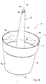
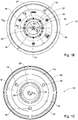
Figs. 1A to 1C are schematic isometric, bottom and top views of a flower-pot according to the disclosed subject matter; -
Fig. 1D is a schematic bottom isometric view of the flower-pot shown inFigs. 1A to 1C ; -
Fig. 1E is a schematic enlarged view of the a portion of the flower-pot shown inFig. 1D , with the catch at a nesting position thereof; -
Fig. 2A is a schematic enlarged view of detail A shown inFig. 1D ; -
Fig. 2B is a schematic isometric enlarged view of detail B shown inFig. 1C ; -
Figs. 3A and 3B are schematic front and side views of a stem of the flower-pot shown inFigs. 1A to 1D ; -
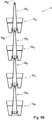
Fig. 4A is a schematic isometric view of a flower-pot system comprising a plurality of flower-pots shown inFigs. 1A to 1D ; -
Figs. 4B and4C are schematic cross-sectional views taken along lines I-I and II-II shown inFig. 4A respectively; -
Figs. 4D and 4E are schematic enlarged views of details C and D shown inFigs. 4B and4C respectively; -
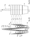
Figs. 5A and5B are schematic front and side views of the flower-pot system shown inFig. 4A ; -
Figs. 5C and5D are schematic cross-sectional views of the flower-pot system taken along lines A-A and B-B shown inFigs. 5A and5B respectively; -
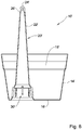
Fig. 6 is a schematic cross-sectional view of another example of a flower-pot according to the disclosed subject matter. - Reference is first made to
Figs. 1A to 1E in which a flower-pot is shown, generally being designated as 10 and comprising ashell 12 having abottom portion 16 and aside portion 14 extending transverse thereto. Theshell 12 defines abasin 15 of the flower-pot 10, delimited by atop rim 18 of theside shell 14. - The
bottom portion 16 of the flower-pot has a nominal dimension d1 whereas thetop rim 18 of the flower-pot 10 has a nominal dimension of D1 > d1 . The conical-like shape of the flower-pot 10 allows, inter alia, stacking and nesting of a plurality of flower-pots 10 within one another as will be explained with respect toFigs. 5A to 5D . - The flower-
pot 10 further comprises ahollow stem 20 extending from thebottom portion 16 of theshell 12, integrally formed with theshell 12, the stem having a first end (shown inFigs. 1B and 1C ) adjacent thebottom portion 16 and a free end remote from thebottom portion 16. - The
bottom portion 16 of the shell is further formed withpre-perforated apertures 19, mechanically weakened points, which the user can perforate in order to form drainage holes at thebottom portion 16. - It is observed that the free end of the
stem 20 projects from thebasin 15 and above the level of thetop rim 18. Thestem 20 is formed with ahook 24 at the free end thereof having arecess 26, and configured for hooking onto a catch (shown inFigs. 1B to 1D ) of a similar flower-pot 10. - As the
stem 20 is integrally formed with thewall 12, and is hollow within, it is observed fromFig. 1D that an opening is formed at thebottom portion 16 of thewall 12. The hollow 25 is configured for accommodating therein acatch member 30. Thecatch 30 comprises agrip portion 32 and twopivot portions 34 via which thecatch 30 is articulated to thestem 20, allowing it to perform pivotal movement. - The pivotal movement allows the
catch 30 to assume various angular positions about its pivot axis, including a hanging position as shown inFig. 1D andFigs. 4A to 4E, and a nesting position as shown inFig. 1E (where the catch is designated 30i) andFigs. 5A to 5D . - As with the flower-
pot 10, thestem 20 is also of conical-like shape having a larger diameter D2 at the first end thereof, adjacent thebottom portion 16 and a smaller diameter d2 at the free end, allowing stacking and nesting as will be explained with respect toFigs. 5A to 5D . - It is further observed from
Figs. 1B and 1C that the flower-pot is formed with support ribs 27 (see alsoFigs. 4D and 4E ) and anabutment step 29, the purpose of which will be later explained in detail with reference toFigs. 5A to 5D . - Turning now to
Figs. 2A and 2B , thecatch 30 is shown in the form of a semi-circle 32. Due to the pivotal articulation to the hollow stem viarecesses 17, the catch is configured for assuming various angular positions about the pivot axis XP (shown inFig. 1B ). - Turning now to
Figs. 4A to 4E , a flower-pot system is shown generally designated as 1 and comprising six flower-pots 10a to 10f consecutively attached to one another. - It is observed that in the position shown above, each flower-pot is suspended from the flower-pot positioned consecutively above it, specifically, the
hook 24 of each flower-pot is grasping thecatch 30 of the corresponding flower-pot above it. In particular, thehook 24d of flower-pot 10d is hooked on thecatch 30c of the flower-pot 10c, thehook 24c of flower-pot 10c is hooked on thecatch 30b of the flower-pot 10b and the hook 24b of flower-pot 10b and so forth. - It is appreciated that the
hook 24a of flower-pot 10a is not engaged with any catch 30 (since there is no flower-pot above it) and thecatch 30f of flower-pot 10f is also not grasped by anyhook 24 since there is not flower-pot 10 below it. - In the position shown above, the
entire system 1 can be suspended from an appropriate anchoring point (not shown) to which thehook 24a of flower-pot 10a can be articulated. - With particular reference to
Figs. 4D and 4E , it is observed that thecatch 30 is fully accommodated within the hollow of thestem 20. This is made possible by the design under which the depth H of the articulation of thecatch 30 is greater than the axial extension h of thecatch 30 in its vertical position. - It is also noted that even in the position shown above (a fully deployed position), the free end of the
stem 20 of each flower-pot 10 (except for 10a) is received within the hollow 25 of theconsecutive stem 20. - This arrangement allows, inter alia, to protect the articulation area between two consecutive flower-
pots 10, making theentire system 1 more durable to external damage and conditions. - In addition, with reference to
Figs. 4D and 4E , it is observed that the bottom opening of thehollow stem 20 is provided withsupport ribs 27 extending along the central axis X and having abottom abutment surface 27 S. In addition, the shell is formed on an inner side thereof with anabutment step 29. - The arrangement is such that when two flower-pots are nested within one another, the
lower abutment surface 27 S abuts theabutment step 29 of the subsequent flower-pot 10. - Attention is now drawn to
Figs. 5A to 5D , in which thesystem 1 is shown in its nesting position, i.e. the four flower-pots 10a to 10d are received within one another when stacked. - It is observed that the basin of one flower-pot, e.g. 10b is configured for almost fully accommodating the shell 12a of the flower-
pot 10a, disposed directly above it, while thehollow stem 20b is configured for almost fully receiving therein thestem 20c of the flower-pot 10c disposed directly below it. - In the position shown above, the
catch 30 of each flower-pot 10 assumes a retracted position in which it is flush with inner surface of the hollow 25 of thestem 20. Due to the semi-circular shape of thecatch 30, in its retracted position it does not obscure the opening of thehollow stem 20, allowing the successivehollow stem 20 to be received therein. - It is also noted that in the stacked position, two subsequent stems do not come into surface contact with one another, thereby preventing friction-locking therebetween. Surface contact is prevented via the
support ribs 27, since the arrangement is such that the abutment between thesupport ribs 27 and theabutment step 29 does not allow thehollow stem 20 to fully rest on the stem accommodated therein. - Turning now to
Fig. 6 , another example of a flower-pot is shown, generally designated as 10'. The difference between the flower-pot 10' and the previously described flower-pot 10 lies in the position of the stem 20' with respect to thebasin 15. - In particular, in the flower-pot 10', the stem 20' is not coaxial with the
basin 15, but rather is disposed adjacent the side wall 14' of theshell 12. Under this design, when suspending consecutive flower-pots 10', the center of gravity of the pots is offset, giving rise to a titled flower-pot system. - It is appreciated that in the arrangement shown in
Fig. 6 , the stem is located to the left of theshell 12, and the hook 24' faces to the left. However, it is appreciated that the direction of thehook 24 and the location of thestem 20 can vary, so that the center of gravity also varies. - Specifically, if the stem is offset in a first offset direction towards the shell, the
hook 24 can face a direction which is offset angularly by N degrees with respect to the first offset direction. Using various flower-pots with various offsets can provide an array of flower-pot systems, each leaning in a different direction due to the variation in the center of gravity. - Those skilled in the art to which this invention pertains will readily appreciate that numerous changes, variations, and modification can be made without departing from the scope of the invention, mutatis mutandis.
Claims (14)
- A hangable container comprising:- a shell (12) with a bottom portion (16) and a top rim (18) spaced from the bottom portion (16), the shell (12) having an inner and an outer surface and defining a basin (15) of the container (10);- a hollow stem (20) extending upwards from the inner surface of the shell (12) and having a first end associated with the bottom portion (16) and a second, free end, remote from the bottom portion (16), and formed with an articulation member (24); and- a catch (30) provided at an inner portion of the hollow stem (20) adjacent said first end, said catch (30) being configured for engagement with an articulation member (24) of a corresponding container (10); wherein an inscribing circle of the bottom portion (16) is of smaller diameter than an inscribing circle of the top rim (18), and an inscribing circle of the first end of the hollow stem (20) is of greater diameter than an inscribing circle of the second, free end of the hollow stem (20), thereby allowing the container (10) to be both nestable and stackable with similar containers,characterized in that the catch (30) is displaceable between a first, operational position in which it is configured for engagement with a corresponding articulation member (24) of a stem (20) and a second, non-operational position in which it is configured to be displaced so as to allow nestable stacking with the similar container,
and in that displacement between the said operational and non-operational positions is provided by way of a pivotal articulation (32, 34) of the catch (30) to the shell (12). - A container according to Claim 1, wherein the articulation member (24) of one container (10) is articulated to the catch (30) of the successive container (10), forming a container chain.
- A container according to Claim 1, wherein the shell (12) is formed with a side portion (14) extending transverse to the bottom portion (16), the end of which is defined by said rim (18).
- A container according to Claim 1, wherein the shell (12) and the stem (20) are integrally formed with one another.
- A container according to Claim 1, wherein the stem (12) is integrally formed with the articulation member (24).
- A container according to Claim 1, wherein the entire container (10) is a uniform injection molding article, but for said catch (30) which is articulated to said stem (20).
- A container according to Claim 1, wherein the container system is configured for assuming at least the following extreme positions:- first, fully deployed position in which the articulation member (24) of each container (10) is articulated to the catch (30) of the corresponding successive container (10); and- second, fully nested position in which the stem (20) of each container (10) is accommodated within the hollow (25) of the stem (20) of the corresponding successive container.
- A container according to Claim 1, wherein the shape of the catch (30) is such that, when in the second, non-operational position, it does not obstruct the hollow (25) of the stem (20), thereby allowing stacking and nesting of successive containers (10).
- A container according to any one of Claims 1, wherein in the second, non-operational position, the catch (30) is configured for being flush with the inner surface of the hollow stem (20).
- A container according to Claim 1, wherein the catch (30) has a curved shape extending along a single plane, and in the second, non-operational position, the catch (30) is configured to be oriented so that the single plane is generally parallel to the outer surface of the bottom portion (16) of the shell (12).
- A container according to Claim 10, wherein the catch (30) is in the shape of an arc or semi-circle, with the ends thereof being articulated to the shell (12).
- A container according to Claim 1, wherein the catch (30) is articulated to the hollow stem (20) at an articulation point of a distance H from the bottom portion, whereas the distance between the articulation point and a point on the catch (30) most remote therefrom is h < H.
- A container according to claim 1, wherein the container (10) is formed with at least one support rib (27) disposed on the outer side of the shell (12) at a bottom opening of the hollow stem (20), said support rib (27) having a bottom abutment surface, said container (10) being further formed, on an inner side of the shell (12), with an abutment step (29) configured for engagement with the abutment surface of a support rib (27) of a subsequent flower-pot.
- A container according to Claim 1, wherein, when two flower-pots (10) are in a second, fully nested position, the arrangement is such that the bottom abutment surface (27s) of the upper flower-pot of the two abuts the abutment step (29) of the lower flower-pot.
Applications Claiming Priority (2)
| Application Number | Priority Date | Filing Date | Title |
|---|---|---|---|
| US201261638511P | 2012-04-26 | 2012-04-26 | |
| PCT/IL2013/050320 WO2013160889A1 (en) | 2012-04-26 | 2013-04-11 | Hangable container |
Publications (2)
| Publication Number | Publication Date |
|---|---|
| EP2844058A1 EP2844058A1 (en) | 2015-03-11 |
| EP2844058B1 true EP2844058B1 (en) | 2017-03-15 |
Family
ID=48325830
Family Applications (1)
| Application Number | Title | Priority Date | Filing Date |
|---|---|---|---|
| EP13721119.9A Not-in-force EP2844058B1 (en) | 2012-04-26 | 2013-04-11 | Hangable container |
Country Status (3)
| Country | Link |
|---|---|
| US (1) | US9363952B2 (en) |
| EP (1) | EP2844058B1 (en) |
| WO (1) | WO2013160889A1 (en) |
Families Citing this family (10)
| Publication number | Priority date | Publication date | Assignee | Title |
|---|---|---|---|---|
| US9516821B1 (en) * | 2013-06-18 | 2016-12-13 | WaterWell Planters, Inc. | Self-watering planter insert assembly |
| US9867340B1 (en) | 2013-06-18 | 2018-01-16 | WaterWell Planters, Inc. | Self-watering two-piece planter |
| US9521811B2 (en) * | 2013-11-08 | 2016-12-20 | Jack Steve Peterson | Plant tower |
| CN204482603U (en) * | 2014-06-16 | 2015-07-22 | 郭天旭 | A kind of string data vertical greening planting unit |
| DE202017100704U1 (en) | 2016-09-13 | 2017-02-21 | Reinhard Simon | Device for vertical planting |
| US20180368334A1 (en) * | 2017-06-22 | 2018-12-27 | Dongguan Shanglan Technology Co., Ltd. | Container for pot culture |
| US12564281B2 (en) * | 2017-07-05 | 2026-03-03 | James Richard Platt | Stackable space saving system and method of use |
| USD891186S1 (en) | 2018-06-12 | 2020-07-28 | Rubbermaid, Inc. | Nesting canning jar |
| US10653276B2 (en) * | 2018-10-19 | 2020-05-19 | Jeffrey Allan Krueger | Container and lid organizer |
| WO2021067430A2 (en) * | 2019-09-30 | 2021-04-08 | Mjnn, Llc | Grow pot apparatus and system |
Family Cites Families (20)
| Publication number | Priority date | Publication date | Assignee | Title |
|---|---|---|---|---|
| GB1267541A (en) | 1969-01-07 | 1972-03-22 | Hindmarch Smith Plastics Ltd | Improvements in or relating to hanging containers primarily for horticultural use |
| US4102081A (en) * | 1977-02-14 | 1978-07-25 | Morrow Edwin M | Plant container |
| US4170089A (en) * | 1977-08-22 | 1979-10-09 | Smrt Thomas John | Hanging flower pot |
| US4227343A (en) | 1979-05-30 | 1980-10-14 | Calvin Espy | Horticulture device for rotating plants due to transpiration and evaporation of moisture |
| GB2135876A (en) | 1983-03-08 | 1984-09-12 | Moulded Plastics | Plant holder |
| US4635394A (en) * | 1984-06-01 | 1987-01-13 | Brown John A | Basket for plants |
| US4912875A (en) * | 1989-02-27 | 1990-04-03 | Plastique Dcn Inc. | Flower pot and saucer |
| CA1305323C (en) * | 1989-09-29 | 1992-07-21 | David G.P. Beaven | Adjustable hanging basket |
| US5052148A (en) * | 1990-08-28 | 1991-10-01 | Sharon Arie N | Hanging rope mounted adjustable position plant pot |
| JP3562838B2 (en) | 1994-08-31 | 2004-09-08 | アイリスオーヤマ株式会社 | Stackable hanging pot |
| US5743044A (en) | 1996-06-24 | 1998-04-28 | Hopkins; Jack A. | Flower pot support bracket |
| US5727347A (en) | 1996-08-08 | 1998-03-17 | Sellers; Kathleen R. | Hanging plant pot and saucer support apparatus |
| FR2766685B1 (en) * | 1997-08-01 | 1999-11-05 | Gilbert Martos | DEVICE FOR MIXED FLORAL LUMINAIRE AND FOUNTAIN OF APPROVAL, SUSPENDED OR LAYING ON THE GROUND. |
| JP2002000080A (en) * | 2000-06-26 | 2002-01-08 | Sugawara Seisakusho:Kk | Hanging pot and its hanging device |
| US6381900B1 (en) | 2000-08-22 | 2002-05-07 | Gerald J. Crowley | Hanging planter |
| US7861888B2 (en) * | 2006-10-26 | 2011-01-04 | Solo Cup Operating Corporation | Stackable stemware |
| BE1017625A3 (en) * | 2007-05-30 | 2009-02-03 | Troyer Jos De | Plant container for outdoor decoration, has two side tanks in which double container plants are placed, and key holders placed in cockpit, where one tank extends along symmetrical axis of container plants |
| US8123187B2 (en) | 2009-07-23 | 2012-02-28 | Zenith Innovation, Llc | Height adjustable and removable container system |
| DE202010007311U1 (en) * | 2010-05-27 | 2010-12-02 | Schneider, Stefan | Variable flower column |
| USD693730S1 (en) | 2011-11-14 | 2013-11-19 | Keter Plastic Ltd. | Flowerpot |
-
2013
- 2013-04-11 EP EP13721119.9A patent/EP2844058B1/en not_active Not-in-force
- 2013-04-11 US US14/397,306 patent/US9363952B2/en not_active Expired - Fee Related
- 2013-04-11 WO PCT/IL2013/050320 patent/WO2013160889A1/en not_active Ceased
Non-Patent Citations (1)
| Title |
|---|
| None * |
Also Published As
| Publication number | Publication date |
|---|---|
| US9363952B2 (en) | 2016-06-14 |
| EP2844058A1 (en) | 2015-03-11 |
| WO2013160889A1 (en) | 2013-10-31 |
| US20150114865A1 (en) | 2015-04-30 |
Similar Documents
| Publication | Publication Date | Title |
|---|---|---|
| US9363952B2 (en) | Hangable container | |
| EP2696671B1 (en) | A container | |
| US7874100B2 (en) | Trellis and tool system | |
| US7774977B2 (en) | Trellis and tool system | |
| US6119393A (en) | Water pond potted plant support | |
| US9192111B2 (en) | Pot for a hydroponic device | |
| US20070186469A1 (en) | Stackable plant pot | |
| US11627705B2 (en) | Hanging planter with obscured attachment point | |
| US8904707B2 (en) | Upside down hanging planter | |
| US20170064915A1 (en) | Systems for cultivating plants with aerial roots | |
| US8091277B1 (en) | Plant container having an elongated member for attachment within the ground and method for use thereof | |
| US8474182B2 (en) | Hanging planter | |
| KR20130005315U (en) | Pot-in-pot for plant cultivation having air-layer | |
| WO2009010773A1 (en) | Improvements in or relating to a planter | |
| KR101884366B1 (en) | Flower pot | |
| US20250134009A1 (en) | Plant holder | |
| NL1044236B1 (en) | Plant holder | |
| KR200499814Y1 (en) | All around pot | |
| JP3119228U (en) | Cultivation container and cultivation container unit | |
| WO2001080625A1 (en) | Seedling nursing vessel | |
| WO2000019805A1 (en) | Plant pot holder | |
| JPH11308933A (en) | Hanging irrigation planter | |
| JP2009201397A (en) | Housing case and gardening container | |
| NL1026647C1 (en) | Plastic plant pot, has recessed base with peripheral wall extending around inner side of support foot for pot | |
| JP2002369625A (en) | flower pot |
Legal Events
| Date | Code | Title | Description |
|---|---|---|---|
| PUAI | Public reference made under article 153(3) epc to a published international application that has entered the european phase |
Free format text: ORIGINAL CODE: 0009012 |
|
| 17P | Request for examination filed |
Effective date: 20141114 |
|
| AK | Designated contracting states |
Kind code of ref document: A1 Designated state(s): AL AT BE BG CH CY CZ DE DK EE ES FI FR GB GR HR HU IE IS IT LI LT LU LV MC MK MT NL NO PL PT RO RS SE SI SK SM TR |
|
| AX | Request for extension of the european patent |
Extension state: BA ME |
|
| DAX | Request for extension of the european patent (deleted) | ||
| 17Q | First examination report despatched |
Effective date: 20160105 |
|
| GRAP | Despatch of communication of intention to grant a patent |
Free format text: ORIGINAL CODE: EPIDOSNIGR1 |
|
| INTG | Intention to grant announced |
Effective date: 20160929 |
|
| GRAS | Grant fee paid |
Free format text: ORIGINAL CODE: EPIDOSNIGR3 |
|
| GRAA | (expected) grant |
Free format text: ORIGINAL CODE: 0009210 |
|
| AK | Designated contracting states |
Kind code of ref document: B1 Designated state(s): AL AT BE BG CH CY CZ DE DK EE ES FI FR GB GR HR HU IE IS IT LI LT LU LV MC MK MT NL NO PL PT RO RS SE SI SK SM TR |
|
| REG | Reference to a national code |
Ref country code: CH Ref legal event code: EP Ref country code: GB Ref legal event code: FG4D |
|
| REG | Reference to a national code |
Ref country code: IE Ref legal event code: FG4D |
|
| REG | Reference to a national code |
Ref country code: AT Ref legal event code: REF Ref document number: 874617 Country of ref document: AT Kind code of ref document: T Effective date: 20170415 |
|
| REG | Reference to a national code |
Ref country code: DE Ref legal event code: R096 Ref document number: 602013018560 Country of ref document: DE |
|
| REG | Reference to a national code |
Ref country code: NL Ref legal event code: MP Effective date: 20170315 |
|
| REG | Reference to a national code |
Ref country code: LT Ref legal event code: MG4D |
|
| PG25 | Lapsed in a contracting state [announced via postgrant information from national office to epo] |
Ref country code: FI Free format text: LAPSE BECAUSE OF FAILURE TO SUBMIT A TRANSLATION OF THE DESCRIPTION OR TO PAY THE FEE WITHIN THE PRESCRIBED TIME-LIMIT Effective date: 20170315 Ref country code: LT Free format text: LAPSE BECAUSE OF FAILURE TO SUBMIT A TRANSLATION OF THE DESCRIPTION OR TO PAY THE FEE WITHIN THE PRESCRIBED TIME-LIMIT Effective date: 20170315 Ref country code: NO Free format text: LAPSE BECAUSE OF FAILURE TO SUBMIT A TRANSLATION OF THE DESCRIPTION OR TO PAY THE FEE WITHIN THE PRESCRIBED TIME-LIMIT Effective date: 20170615 Ref country code: GR Free format text: LAPSE BECAUSE OF FAILURE TO SUBMIT A TRANSLATION OF THE DESCRIPTION OR TO PAY THE FEE WITHIN THE PRESCRIBED TIME-LIMIT Effective date: 20170616 Ref country code: HR Free format text: LAPSE BECAUSE OF FAILURE TO SUBMIT A TRANSLATION OF THE DESCRIPTION OR TO PAY THE FEE WITHIN THE PRESCRIBED TIME-LIMIT Effective date: 20170315 |
|
| REG | Reference to a national code |
Ref country code: AT Ref legal event code: MK05 Ref document number: 874617 Country of ref document: AT Kind code of ref document: T Effective date: 20170315 |
|
| PG25 | Lapsed in a contracting state [announced via postgrant information from national office to epo] |
Ref country code: SE Free format text: LAPSE BECAUSE OF FAILURE TO SUBMIT A TRANSLATION OF THE DESCRIPTION OR TO PAY THE FEE WITHIN THE PRESCRIBED TIME-LIMIT Effective date: 20170315 Ref country code: BG Free format text: LAPSE BECAUSE OF FAILURE TO SUBMIT A TRANSLATION OF THE DESCRIPTION OR TO PAY THE FEE WITHIN THE PRESCRIBED TIME-LIMIT Effective date: 20170615 Ref country code: LV Free format text: LAPSE BECAUSE OF FAILURE TO SUBMIT A TRANSLATION OF THE DESCRIPTION OR TO PAY THE FEE WITHIN THE PRESCRIBED TIME-LIMIT Effective date: 20170315 Ref country code: RS Free format text: LAPSE BECAUSE OF FAILURE TO SUBMIT A TRANSLATION OF THE DESCRIPTION OR TO PAY THE FEE WITHIN THE PRESCRIBED TIME-LIMIT Effective date: 20170315 |
|
| PG25 | Lapsed in a contracting state [announced via postgrant information from national office to epo] |
Ref country code: NL Free format text: LAPSE BECAUSE OF FAILURE TO SUBMIT A TRANSLATION OF THE DESCRIPTION OR TO PAY THE FEE WITHIN THE PRESCRIBED TIME-LIMIT Effective date: 20170315 |
|
| PG25 | Lapsed in a contracting state [announced via postgrant information from national office to epo] |
Ref country code: IT Free format text: LAPSE BECAUSE OF FAILURE TO SUBMIT A TRANSLATION OF THE DESCRIPTION OR TO PAY THE FEE WITHIN THE PRESCRIBED TIME-LIMIT Effective date: 20170315 Ref country code: ES Free format text: LAPSE BECAUSE OF FAILURE TO SUBMIT A TRANSLATION OF THE DESCRIPTION OR TO PAY THE FEE WITHIN THE PRESCRIBED TIME-LIMIT Effective date: 20170315 Ref country code: AT Free format text: LAPSE BECAUSE OF FAILURE TO SUBMIT A TRANSLATION OF THE DESCRIPTION OR TO PAY THE FEE WITHIN THE PRESCRIBED TIME-LIMIT Effective date: 20170315 Ref country code: EE Free format text: LAPSE BECAUSE OF FAILURE TO SUBMIT A TRANSLATION OF THE DESCRIPTION OR TO PAY THE FEE WITHIN THE PRESCRIBED TIME-LIMIT Effective date: 20170315 Ref country code: CZ Free format text: LAPSE BECAUSE OF FAILURE TO SUBMIT A TRANSLATION OF THE DESCRIPTION OR TO PAY THE FEE WITHIN THE PRESCRIBED TIME-LIMIT Effective date: 20170315 Ref country code: RO Free format text: LAPSE BECAUSE OF FAILURE TO SUBMIT A TRANSLATION OF THE DESCRIPTION OR TO PAY THE FEE WITHIN THE PRESCRIBED TIME-LIMIT Effective date: 20170315 Ref country code: SK Free format text: LAPSE BECAUSE OF FAILURE TO SUBMIT A TRANSLATION OF THE DESCRIPTION OR TO PAY THE FEE WITHIN THE PRESCRIBED TIME-LIMIT Effective date: 20170315 |
|
| REG | Reference to a national code |
Ref country code: DE Ref legal event code: R119 Ref document number: 602013018560 Country of ref document: DE |
|
| PG25 | Lapsed in a contracting state [announced via postgrant information from national office to epo] |
Ref country code: SM Free format text: LAPSE BECAUSE OF FAILURE TO SUBMIT A TRANSLATION OF THE DESCRIPTION OR TO PAY THE FEE WITHIN THE PRESCRIBED TIME-LIMIT Effective date: 20170315 Ref country code: PT Free format text: LAPSE BECAUSE OF FAILURE TO SUBMIT A TRANSLATION OF THE DESCRIPTION OR TO PAY THE FEE WITHIN THE PRESCRIBED TIME-LIMIT Effective date: 20170717 Ref country code: PL Free format text: LAPSE BECAUSE OF FAILURE TO SUBMIT A TRANSLATION OF THE DESCRIPTION OR TO PAY THE FEE WITHIN THE PRESCRIBED TIME-LIMIT Effective date: 20170315 Ref country code: IS Free format text: LAPSE BECAUSE OF FAILURE TO SUBMIT A TRANSLATION OF THE DESCRIPTION OR TO PAY THE FEE WITHIN THE PRESCRIBED TIME-LIMIT Effective date: 20170715 |
|
| REG | Reference to a national code |
Ref country code: CH Ref legal event code: PL |
|
| PLBE | No opposition filed within time limit |
Free format text: ORIGINAL CODE: 0009261 |
|
| STAA | Information on the status of an ep patent application or granted ep patent |
Free format text: STATUS: NO OPPOSITION FILED WITHIN TIME LIMIT |
|
| REG | Reference to a national code |
Ref country code: IE Ref legal event code: MM4A |
|
| REG | Reference to a national code |
Ref country code: FR Ref legal event code: ST Effective date: 20171229 |
|
| PG25 | Lapsed in a contracting state [announced via postgrant information from national office to epo] |
Ref country code: MC Free format text: LAPSE BECAUSE OF FAILURE TO SUBMIT A TRANSLATION OF THE DESCRIPTION OR TO PAY THE FEE WITHIN THE PRESCRIBED TIME-LIMIT Effective date: 20170315 Ref country code: DK Free format text: LAPSE BECAUSE OF FAILURE TO SUBMIT A TRANSLATION OF THE DESCRIPTION OR TO PAY THE FEE WITHIN THE PRESCRIBED TIME-LIMIT Effective date: 20170315 Ref country code: DE Free format text: LAPSE BECAUSE OF NON-PAYMENT OF DUE FEES Effective date: 20171103 Ref country code: FR Free format text: LAPSE BECAUSE OF NON-PAYMENT OF DUE FEES Effective date: 20170515 |
|
| 26N | No opposition filed |
Effective date: 20171218 |
|
| GBPC | Gb: european patent ceased through non-payment of renewal fee |
Effective date: 20170615 |
|
| PG25 | Lapsed in a contracting state [announced via postgrant information from national office to epo] |
Ref country code: LI Free format text: LAPSE BECAUSE OF NON-PAYMENT OF DUE FEES Effective date: 20170430 Ref country code: LU Free format text: LAPSE BECAUSE OF NON-PAYMENT OF DUE FEES Effective date: 20170411 Ref country code: CH Free format text: LAPSE BECAUSE OF NON-PAYMENT OF DUE FEES Effective date: 20170430 Ref country code: SI Free format text: LAPSE BECAUSE OF FAILURE TO SUBMIT A TRANSLATION OF THE DESCRIPTION OR TO PAY THE FEE WITHIN THE PRESCRIBED TIME-LIMIT Effective date: 20170315 |
|
| REG | Reference to a national code |
Ref country code: BE Ref legal event code: MM Effective date: 20170430 |
|
| PG25 | Lapsed in a contracting state [announced via postgrant information from national office to epo] |
Ref country code: GB Free format text: LAPSE BECAUSE OF NON-PAYMENT OF DUE FEES Effective date: 20170615 Ref country code: IE Free format text: LAPSE BECAUSE OF NON-PAYMENT OF DUE FEES Effective date: 20170411 |
|
| PG25 | Lapsed in a contracting state [announced via postgrant information from national office to epo] |
Ref country code: BE Free format text: LAPSE BECAUSE OF NON-PAYMENT OF DUE FEES Effective date: 20170430 |
|
| PG25 | Lapsed in a contracting state [announced via postgrant information from national office to epo] |
Ref country code: MT Free format text: LAPSE BECAUSE OF NON-PAYMENT OF DUE FEES Effective date: 20170411 |
|
| PG25 | Lapsed in a contracting state [announced via postgrant information from national office to epo] |
Ref country code: HU Free format text: LAPSE BECAUSE OF FAILURE TO SUBMIT A TRANSLATION OF THE DESCRIPTION OR TO PAY THE FEE WITHIN THE PRESCRIBED TIME-LIMIT; INVALID AB INITIO Effective date: 20130411 |
|
| PG25 | Lapsed in a contracting state [announced via postgrant information from national office to epo] |
Ref country code: CY Free format text: LAPSE BECAUSE OF FAILURE TO SUBMIT A TRANSLATION OF THE DESCRIPTION OR TO PAY THE FEE WITHIN THE PRESCRIBED TIME-LIMIT Effective date: 20170315 |
|
| PG25 | Lapsed in a contracting state [announced via postgrant information from national office to epo] |
Ref country code: MK Free format text: LAPSE BECAUSE OF FAILURE TO SUBMIT A TRANSLATION OF THE DESCRIPTION OR TO PAY THE FEE WITHIN THE PRESCRIBED TIME-LIMIT Effective date: 20170315 |
|
| PG25 | Lapsed in a contracting state [announced via postgrant information from national office to epo] |
Ref country code: TR Free format text: LAPSE BECAUSE OF FAILURE TO SUBMIT A TRANSLATION OF THE DESCRIPTION OR TO PAY THE FEE WITHIN THE PRESCRIBED TIME-LIMIT Effective date: 20170315 |
|
| PG25 | Lapsed in a contracting state [announced via postgrant information from national office to epo] |
Ref country code: AL Free format text: LAPSE BECAUSE OF FAILURE TO SUBMIT A TRANSLATION OF THE DESCRIPTION OR TO PAY THE FEE WITHIN THE PRESCRIBED TIME-LIMIT Effective date: 20170315 |