EP2843970A1 - Speaker - Google Patents
Speaker Download PDFInfo
- Publication number
- EP2843970A1 EP2843970A1 EP12875465.2A EP12875465A EP2843970A1 EP 2843970 A1 EP2843970 A1 EP 2843970A1 EP 12875465 A EP12875465 A EP 12875465A EP 2843970 A1 EP2843970 A1 EP 2843970A1
- Authority
- EP
- European Patent Office
- Prior art keywords
- magnetostrictive elements
- elements
- speaker
- magnetostrictive
- circuit board
- Prior art date
- Legal status (The legal status is an assumption and is not a legal conclusion. Google has not performed a legal analysis and makes no representation as to the accuracy of the status listed.)
- Withdrawn
Links
Images
Classifications
-
- H—ELECTRICITY
- H04—ELECTRIC COMMUNICATION TECHNIQUE
- H04R—LOUDSPEAKERS, MICROPHONES, GRAMOPHONE PICK-UPS OR LIKE ACOUSTIC ELECTROMECHANICAL TRANSDUCERS; ELECTRIC HEARING AIDS; PUBLIC ADDRESS SYSTEMS
- H04R15/00—Magnetostrictive transducers
-
- H—ELECTRICITY
- H04—ELECTRIC COMMUNICATION TECHNIQUE
- H04R—LOUDSPEAKERS, MICROPHONES, GRAMOPHONE PICK-UPS OR LIKE ACOUSTIC ELECTROMECHANICAL TRANSDUCERS; ELECTRIC HEARING AIDS; PUBLIC ADDRESS SYSTEMS
- H04R1/00—Details of transducers, loudspeakers or microphones
- H04R1/20—Arrangements for obtaining desired frequency or directional characteristics
- H04R1/32—Arrangements for obtaining desired frequency or directional characteristics for obtaining desired directional characteristic only
- H04R1/40—Arrangements for obtaining desired frequency or directional characteristics for obtaining desired directional characteristic only by combining a number of identical transducers
- H04R1/403—Arrangements for obtaining desired frequency or directional characteristics for obtaining desired directional characteristic only by combining a number of identical transducers loud-speakers
-
- H—ELECTRICITY
- H04—ELECTRIC COMMUNICATION TECHNIQUE
- H04R—LOUDSPEAKERS, MICROPHONES, GRAMOPHONE PICK-UPS OR LIKE ACOUSTIC ELECTROMECHANICAL TRANSDUCERS; ELECTRIC HEARING AIDS; PUBLIC ADDRESS SYSTEMS
- H04R3/00—Circuits for transducers
-
- H—ELECTRICITY
- H04—ELECTRIC COMMUNICATION TECHNIQUE
- H04R—LOUDSPEAKERS, MICROPHONES, GRAMOPHONE PICK-UPS OR LIKE ACOUSTIC ELECTROMECHANICAL TRANSDUCERS; ELECTRIC HEARING AIDS; PUBLIC ADDRESS SYSTEMS
- H04R2201/00—Details of transducers, loudspeakers or microphones covered by H04R1/00 but not provided for in any of its subgroups
- H04R2201/40—Details of arrangements for obtaining desired directional characteristic by combining a number of identical transducers covered by H04R1/40 but not provided for in any of its subgroups
- H04R2201/401—2D or 3D arrays of transducers
-
- H—ELECTRICITY
- H04—ELECTRIC COMMUNICATION TECHNIQUE
- H04R—LOUDSPEAKERS, MICROPHONES, GRAMOPHONE PICK-UPS OR LIKE ACOUSTIC ELECTROMECHANICAL TRANSDUCERS; ELECTRIC HEARING AIDS; PUBLIC ADDRESS SYSTEMS
- H04R2217/00—Details of magnetostrictive, piezoelectric, or electrostrictive transducers covered by H04R15/00 or H04R17/00 but not provided for in any of their subgroups
- H04R2217/03—Parametric transducers where sound is generated or captured by the acoustic demodulation of amplitude modulated ultrasonic waves
Definitions
- the present invention relates to a speaker.
- a speaker that uses ultrasonic waves as carrier waves called a parametric speaker (for example, refer to Patent Document 1).
- a plurality of piezoelectric vibrators each having a piezoelectric element are arranged in a matrix, and modulated ultrasonic waves (carrier waves) are emitted into the air from the respective piezoelectric vibrators.
- carrier waves modulated ultrasonic waves
- Patent Document 1 JP 2012-029102
- an object of the present invention is to provide a speaker capable of reducing power consumption under certain circumstances and also making vibrating elements resistant to damage even if subjected to an impact due to falling or the like.
- a speaker according to the present invention is characterized by comprising a circuit board, a plurality of magnetostrictive elements arranged on the circuit board, and voice coils arranged on respective peripheries of the plurality of magnetostrictive elements.
- the magnetostrictive elements which are vibrating elements, can be made resistant to damage even if subjected to an impact due to falling or the like.
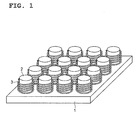
- FIG. 1 is a perspective view of main section of a speaker as one embodiment of the present invention.
- FIG. 1 is a perspective view of main section of a speaker as one embodiment of the present invention.
- This speaker includes a circuit board 1. At a plurality of locations on an upper surface of the circuit board 1, lower surfaces of a plurality of columnar-shaped magnetostrictive elements 2 made of ferrite or the like are fixed via an adhesive, respectively (not depicted in the drawing). That is, each of the magnetostrictive elements 2 is provided on the circuit board 1 so that a center axis thereof is perpendicular to the circuit board 1.
- the magnetostrictive elements 2 are arranged in a four-by-four matrix, as an example. Also, as an example, the outer diameter of each of magnetostrictive elements 2 is approximately 10 mm.
- voice coils 3 are arranged on the respective peripheries of the magnetostrictive elements 2. A lower portion of each of the voice coils 3 is fixed to the upper surface of the circuit board 1 via an adhesive (not depicted in the drawing).
- the magnetostrictive elements 2 themselves expand and contract in their center axis direction (height direction).
- ultrasonic waves in a band equal to or higher than a frequency of 20 kHz are generated.
- modulated ultrasonic waves carrier waves
- these emitted ultrasonic waves are subjected to a non-linear phenomenon of air, and whereby a demodulated audible sound is generated.
- the magnetostrictive elements 2 made of ferrite or the like are used, the magnetostrictive elements 2 can be made resistant to damage even if subjected to an impact due to falling or the like, compared with piezoelectric vibrators using a ceramic material, which is a brittle material, as piezoelectric elements. Also, in this speaker, since the magnetostrictive elements 2 themselves vibrate, a dedicated vibrating plate is not required, and whereby the miniaturization and thinning of the speaker can be achieved.
- directivity in a parametric speaker is determined by straight-traveling property of carrier waves (ultrasonic waves).
- carrier waves ultrasonic waves
- directivity becomes sharper as a shift is made to a higher frequency band.
- impedance decreases due to characteristics of the piezoelectric elements, the amount current consumption increases, and power consumption increases.
- the magnetostrictive elements 2 made of ferrite or the like are used, impedance does not change even if a shift is made to a higher frequency band. Accordingly, the amount of current consumption does not increase and power consumption can be reduced, compared with the case of piezoelectric vibrators having piezoelectric elements.
- directivity can be easily controlled. That is, since the magnetostrictive element 2 has a fundamental resonance frequency, directivity can be easily controlled by adjusting the fundamental resonance frequency of each of the plurality of magnetostrictive elements 2 arranged in a matrix and arbitrarily changing the magnetostrictive elements 2 to be driven. As a result, directivity can be easily adjusted according to the use environment of the user.
- the fundamental resonance frequency of the magnetostrictive element 2 since the thickness (height), the outer shape, and the like of the magnetostrictive element 2 can be taken as determining factors for the fundamental resonance frequency, these may be adjusted as appropriate. For example, the fundamental resonance frequency is reduced when the thickness of the magnetostrictive element 2 is made thinner. Also, the fundamental resonance frequency is reduced when the outer diameter of the magnetostrictive element 2 is increased.
- the band of an audible sound is expanded due to interference of the ultrasonic waves with different frequencies, and whereby sound pressure is amplified. Accordingly, the quality of the audible sound can be enhanced.
- the invention of Supplementary Note 1 provides a speaker comprising a circuit board, a plurality of magnetostrictive elements arranged on the circuit board, and voice coils arranged on respective peripheries of the plurality of magnetostrictive elements.
- the invention of Supplementary Note 2 provides the speaker according to Supplementary Note 1, wherein each of the magnetostrictive elements has a columnar shape, and is provided on the circuit board so that a center axis thereof is perpendicular to the circuit board.
- Supplementary Note 3 provides the speaker according to Supplementary Note 1 or 2, wherein the magnetostrictive elements are arranged in a matrix.
- Supplementary Note 4 provides the speaker according to any one of Supplementary Notes 1 to 3, wherein the plurality of magnetostrictive elements has different fundamental resonance frequencies.
Landscapes
- Physics & Mathematics (AREA)
- Engineering & Computer Science (AREA)
- Acoustics & Sound (AREA)
- Signal Processing (AREA)
- Health & Medical Sciences (AREA)
- Otolaryngology (AREA)
- Circuit For Audible Band Transducer (AREA)
- Obtaining Desirable Characteristics In Audible-Bandwidth Transducers (AREA)
- Transducers For Ultrasonic Waves (AREA)
Abstract
Description
- The present invention relates to a speaker.
- In conventional speakers, there is a speaker that uses ultrasonic waves as carrier waves called a parametric speaker (for example, refer to Patent Document 1). In the speaker described in
Patent Document 1, a plurality of piezoelectric vibrators each having a piezoelectric element are arranged in a matrix, and modulated ultrasonic waves (carrier waves) are emitted into the air from the respective piezoelectric vibrators. With these emitted ultrasonic waves subjected to a non-linear phenomenon of air, a demodulated audible sound is generated. - Patent Document 1:
JP 2012-029102 - However, in the conventional speaker described above, since piezoelectric vibrators are used as a source for generating ultrasonic waves, the amount of current consumption under certain circumstances, which will be described further below, disadvantageously increases due to characteristics of the piezoelectric elements of the piezoelectric vibrators, and whereby power consumption increases. Moreover, when a ceramic material, which is a brittle material, is used for piezoelectric elements, the piezoelectric elements may be damaged when subjected to an impact due to falling or the like.
- Thus, an object of the present invention is to provide a speaker capable of reducing power consumption under certain circumstances and also making vibrating elements resistant to damage even if subjected to an impact due to falling or the like.
- A speaker according to the present invention is characterized by comprising a circuit board, a plurality of magnetostrictive elements arranged on the circuit board, and voice coils arranged on respective peripheries of the plurality of magnetostrictive elements.
- According to the present invention, power consumption under certain circumstances can be reduced. Also, the magnetostrictive elements, which are vibrating elements, can be made resistant to damage even if subjected to an impact due to falling or the like.
-
FIG. 1 is a perspective view of main section of a speaker as one embodiment of the present invention. -
FIG. 1 is a perspective view of main section of a speaker as one embodiment of the present invention. This speaker includes acircuit board 1. At a plurality of locations on an upper surface of thecircuit board 1, lower surfaces of a plurality of columnar-shapedmagnetostrictive elements 2 made of ferrite or the like are fixed via an adhesive, respectively (not depicted in the drawing). That is, each of themagnetostrictive elements 2 is provided on thecircuit board 1 so that a center axis thereof is perpendicular to thecircuit board 1. - The
magnetostrictive elements 2 are arranged in a four-by-four matrix, as an example. Also, as an example, the outer diameter of each ofmagnetostrictive elements 2 is approximately 10 mm. On the respective peripheries of themagnetostrictive elements 2,voice coils 3 are arranged. A lower portion of each of thevoice coils 3 is fixed to the upper surface of thecircuit board 1 via an adhesive (not depicted in the drawing). - In this speaker, when current flows to the voice coils 3, the
magnetostrictive elements 2 themselves expand and contract in their center axis direction (height direction). When themagnetostrictive elements 2 themselves expand and contract in their center axis direction, ultrasonic waves in a band equal to or higher than a frequency of 20 kHz are generated. Then, when modulated ultrasonic waves (carrier waves) are emitted into the air from themagnetostrictive elements 2, these emitted ultrasonic waves are subjected to a non-linear phenomenon of air, and whereby a demodulated audible sound is generated. - In this speaker, since the
magnetostrictive elements 2 made of ferrite or the like are used, themagnetostrictive elements 2 can be made resistant to damage even if subjected to an impact due to falling or the like, compared with piezoelectric vibrators using a ceramic material, which is a brittle material, as piezoelectric elements. Also, in this speaker, since themagnetostrictive elements 2 themselves vibrate, a dedicated vibrating plate is not required, and whereby the miniaturization and thinning of the speaker can be achieved. - Here, directivity in a parametric speaker is determined by straight-traveling property of carrier waves (ultrasonic waves). In the case of piezoelectric vibrators having piezoelectric elements, directivity becomes sharper as a shift is made to a higher frequency band. However, impedance decreases due to characteristics of the piezoelectric elements, the amount current consumption increases, and power consumption increases. By contrast, in this speaker, since the
magnetostrictive elements 2 made of ferrite or the like are used, impedance does not change even if a shift is made to a higher frequency band. Accordingly, the amount of current consumption does not increase and power consumption can be reduced, compared with the case of piezoelectric vibrators having piezoelectric elements. - Also, in this speaker, directivity can be easily controlled. That is, since the
magnetostrictive element 2 has a fundamental resonance frequency, directivity can be easily controlled by adjusting the fundamental resonance frequency of each of the plurality ofmagnetostrictive elements 2 arranged in a matrix and arbitrarily changing themagnetostrictive elements 2 to be driven. As a result, directivity can be easily adjusted according to the use environment of the user. - As a method of adjusting the fundamental resonance frequency of the
magnetostrictive element 2, since the thickness (height), the outer shape, and the like of themagnetostrictive element 2 can be taken as determining factors for the fundamental resonance frequency, these may be adjusted as appropriate. For example, the fundamental resonance frequency is reduced when the thickness of themagnetostrictive element 2 is made thinner. Also, the fundamental resonance frequency is reduced when the outer diameter of themagnetostrictive element 2 is increased. - Furthermore, in this speaker, when a plurality of ultrasonic waves with different frequencies are emitted from the plurality of
magnetostrictive elements 2, the band of an audible sound is expanded due to interference of the ultrasonic waves with different frequencies, and whereby sound pressure is amplified. Accordingly, the quality of the audible sound can be enhanced. - Hereinafter, several embodiments of this invention are summarized in the Supplementary Notes described below.
- The invention of
Supplementary Note 1 provides a speaker comprising a circuit board, a plurality of magnetostrictive elements arranged on the circuit board, and voice coils arranged on respective peripheries of the plurality of magnetostrictive elements. - The invention of
Supplementary Note 2 provides the speaker according toSupplementary Note 1, wherein each of the magnetostrictive elements has a columnar shape, and is provided on the circuit board so that a center axis thereof is perpendicular to the circuit board. - The invention of
Supplementary Note 3 provides the speaker according toSupplementary Note - The invention of Supplementary Note 4 provides the speaker according to any one of
Supplementary Notes 1 to 3, wherein the plurality of magnetostrictive elements has different fundamental resonance frequencies. -
- 1
- CIRCUIT BOARD
- 2
- MAGNETOSTRICTIVE ELEMENT
- 3
- VOICE COIL
Claims (4)
- A speaker comprising a circuit board, a plurality of magnetostrictive elements arranged on the circuit board, and voice coils arranged on respective peripheries of the plurality of magnetostrictive elements.
- The speaker according to claim 1, wherein each of the magnetostrictive elements has a columnar shape, and is provided on the circuit board so that a center axis thereof is perpendicular to the circuit board.
- The speaker according to claim 1 or 2, wherein the magnetostrictive elements are arranged in a matrix.
- The speaker according to any one of claims 1 to 3, wherein the plurality of magnetostrictive elements has different fundamental resonance frequencies.
Applications Claiming Priority (2)
| Application Number | Priority Date | Filing Date | Title |
|---|---|---|---|
| JP2012102415 | 2012-04-27 | ||
| PCT/JP2012/007751 WO2013160975A1 (en) | 2012-04-27 | 2012-12-04 | Speaker |
Publications (2)
| Publication Number | Publication Date |
|---|---|
| EP2843970A1 true EP2843970A1 (en) | 2015-03-04 |
| EP2843970A4 EP2843970A4 (en) | 2015-12-09 |
Family
ID=49482348
Family Applications (1)
| Application Number | Title | Priority Date | Filing Date |
|---|---|---|---|
| EP12875465.2A Withdrawn EP2843970A4 (en) | 2012-04-27 | 2012-12-04 | Speaker |
Country Status (5)
| Country | Link |
|---|---|
| US (1) | US9307324B2 (en) |
| EP (1) | EP2843970A4 (en) |
| JP (1) | JPWO2013160975A1 (en) |
| CN (1) | CN104247455A (en) |
| WO (1) | WO2013160975A1 (en) |
Family Cites Families (10)
| Publication number | Priority date | Publication date | Assignee | Title |
|---|---|---|---|---|
| US2421263A (en) | 1940-01-03 | 1947-05-27 | Rca Corp | Magnetostrictive electroacoustic transducer |
| JP2000050387A (en) * | 1998-07-16 | 2000-02-18 | Massachusetts Inst Of Technol <Mit> | Parametric audio system |
| US20060233404A1 (en) | 2000-03-28 | 2006-10-19 | American Technology Corporation. | Horn array emitter |
| JP2002189486A (en) * | 2000-12-20 | 2002-07-05 | Matsushita Electric Ind Co Ltd | Portable audio player |
| JP2004297726A (en) * | 2003-03-28 | 2004-10-21 | Mitsubishi Electric Engineering Co Ltd | Electroacoustic transducer |
| JP2006245731A (en) | 2005-03-01 | 2006-09-14 | Citizen Watch Co Ltd | Directional speaker |
| JP2008306636A (en) * | 2007-06-11 | 2008-12-18 | Audio Technica Corp | Condenser microphone |
| JP2010263512A (en) * | 2009-05-11 | 2010-11-18 | Sony Corp | Speaker device |
| KR101061590B1 (en) * | 2009-06-23 | 2011-09-02 | 서울대학교산학협력단 | Magnetostrictive transducers, structural diagnostic devices and structural diagnostic methods using the same |
| JP2012029102A (en) | 2010-07-23 | 2012-02-09 | Nec Casio Mobile Communications Ltd | Acoustic system and acoustic equipment |
-
2012
- 2012-12-04 US US14/396,756 patent/US9307324B2/en not_active Expired - Fee Related
- 2012-12-04 JP JP2014512037A patent/JPWO2013160975A1/en active Pending
- 2012-12-04 CN CN201280072680.7A patent/CN104247455A/en active Pending
- 2012-12-04 WO PCT/JP2012/007751 patent/WO2013160975A1/en not_active Ceased
- 2012-12-04 EP EP12875465.2A patent/EP2843970A4/en not_active Withdrawn
Also Published As
| Publication number | Publication date |
|---|---|
| EP2843970A4 (en) | 2015-12-09 |
| US20150098594A1 (en) | 2015-04-09 |
| JPWO2013160975A1 (en) | 2015-12-21 |
| CN104247455A (en) | 2014-12-24 |
| US9307324B2 (en) | 2016-04-05 |
| WO2013160975A1 (en) | 2013-10-31 |
Similar Documents
| Publication | Publication Date | Title |
|---|---|---|
| US11259121B2 (en) | Surface speaker | |
| JP5327317B2 (en) | Piezoelectric actuators and acoustic components | |
| US9654881B2 (en) | Electroacoustic transducer | |
| TW201941621A (en) | Panel audio loudspeaker electromagnetic actuator | |
| JP5652813B2 (en) | Electroacoustic transducer and electronic device using the same | |
| CN105657625A (en) | Electroacoustic transducer | |
| WO2010034874A1 (en) | Dual-mode loudspeaker | |
| US20130257551A1 (en) | Oscillator device and electronic instrument | |
| JP5821241B2 (en) | Speaker device and electronic device | |
| JP5359818B2 (en) | Piezoelectric actuator and electronic device | |
| JPWO2012132261A1 (en) | Oscillator and electronic device | |
| US9307324B2 (en) | Speaker | |
| JP5812009B2 (en) | Oscillator and electronic device | |
| EP2928208A1 (en) | Electroacoustic transducer, manufacturing method therefor, and electronic device utilizing electroacoustic transducer | |
| US9236042B2 (en) | Oscillation device | |
| JP2016139970A (en) | Acoustic generator and electronic apparatus using the same | |
| US20180367912A1 (en) | Membrane for Sounding Device | |
| JP2012217013A (en) | Oscillation device and electronic apparatus | |
| JP2015005897A (en) | Piezoelectric type electro-acoustic transducer and electronic apparatus | |
| TWI604736B (en) | Speaker unit | |
| JP2012217037A (en) | Electronic device | |
| JP5505165B2 (en) | Oscillator | |
| JP2014086941A (en) | Electro-acoustic transducer and electronic apparatus | |
| JP2013183374A (en) | Oscillator and method for manufacturing the same | |
| JP2012217019A (en) | Oscillation device and electronic apparatus |
Legal Events
| Date | Code | Title | Description |
|---|---|---|---|
| PUAI | Public reference made under article 153(3) epc to a published international application that has entered the european phase |
Free format text: ORIGINAL CODE: 0009012 |
|
| 17P | Request for examination filed |
Effective date: 20141127 |
|
| AK | Designated contracting states |
Kind code of ref document: A1 Designated state(s): AL AT BE BG CH CY CZ DE DK EE ES FI FR GB GR HR HU IE IS IT LI LT LU LV MC MK MT NL NO PL PT RO RS SE SI SK SM TR |
|
| AX | Request for extension of the european patent |
Extension state: BA ME |
|
| DAX | Request for extension of the european patent (deleted) | ||
| RAP1 | Party data changed (applicant data changed or rights of an application transferred) |
Owner name: NEC CORPORATION |
|
| RA4 | Supplementary search report drawn up and despatched (corrected) |
Effective date: 20151106 |
|
| RIC1 | Information provided on ipc code assigned before grant |
Ipc: H01L 41/12 20060101ALI20151102BHEP Ipc: H04R 15/00 20060101ALI20151102BHEP Ipc: H04R 1/40 20060101AFI20151102BHEP |
|
| 17Q | First examination report despatched |
Effective date: 20180503 |
|
| GRAP | Despatch of communication of intention to grant a patent |
Free format text: ORIGINAL CODE: EPIDOSNIGR1 |
|
| INTG | Intention to grant announced |
Effective date: 20190301 |
|
| RIN1 | Information on inventor provided before grant (corrected) |
Inventor name: ONISHI, YASUHARU Inventor name: SATOU, SHIGEO Inventor name: KOMODA, MOTOYOSHI Inventor name: KURODA, JUN |
|
| INTG | Intention to grant announced |
Effective date: 20190301 |
|
| STAA | Information on the status of an ep patent application or granted ep patent |
Free format text: STATUS: THE APPLICATION IS DEEMED TO BE WITHDRAWN |
|
| 18D | Application deemed to be withdrawn |
Effective date: 20190712 |