EP2843804A2 - Permanent magnet-embedded type rotary electric machine - Google Patents
Permanent magnet-embedded type rotary electric machine Download PDFInfo
- Publication number
- EP2843804A2 EP2843804A2 EP14180593.7A EP14180593A EP2843804A2 EP 2843804 A2 EP2843804 A2 EP 2843804A2 EP 14180593 A EP14180593 A EP 14180593A EP 2843804 A2 EP2843804 A2 EP 2843804A2
- Authority
- EP
- European Patent Office
- Prior art keywords
- rotor
- circumferential surface
- designates
- outer circumferential
- permanent magnet
- Prior art date
- Legal status (The legal status is an assumption and is not a legal conclusion. Google has not performed a legal analysis and makes no representation as to the accuracy of the status listed.)
- Withdrawn
Links
Images

Classifications
-
- H—ELECTRICITY
- H02—GENERATION; CONVERSION OR DISTRIBUTION OF ELECTRIC POWER
- H02K—DYNAMO-ELECTRIC MACHINES
- H02K1/00—Details of the magnetic circuit
- H02K1/06—Details of the magnetic circuit characterised by the shape, form or construction
- H02K1/22—Rotating parts of the magnetic circuit
- H02K1/27—Rotor cores with permanent magnets
- H02K1/2706—Inner rotors
- H02K1/272—Inner rotors the magnetisation axis of the magnets being perpendicular to the rotor axis
- H02K1/274—Inner rotors the magnetisation axis of the magnets being perpendicular to the rotor axis the rotor consisting of two or more circumferentially positioned magnets
- H02K1/2753—Inner rotors the magnetisation axis of the magnets being perpendicular to the rotor axis the rotor consisting of two or more circumferentially positioned magnets the rotor consisting of magnets or groups of magnets arranged with alternating polarity
- H02K1/276—Magnets embedded in the magnetic core, e.g. interior permanent magnets [IPM]
- H02K1/2766—Magnets embedded in the magnetic core, e.g. interior permanent magnets [IPM] having a flux concentration effect
-
- H—ELECTRICITY
- H02—GENERATION; CONVERSION OR DISTRIBUTION OF ELECTRIC POWER
- H02K—DYNAMO-ELECTRIC MACHINES
- H02K29/00—Motors or generators having non-mechanical commutating devices, e.g. discharge tubes or semiconductor devices
- H02K29/03—Motors or generators having non-mechanical commutating devices, e.g. discharge tubes or semiconductor devices with a magnetic circuit specially adapted for avoiding torque ripples or self-starting problems
-
- H—ELECTRICITY
- H02—GENERATION; CONVERSION OR DISTRIBUTION OF ELECTRIC POWER
- H02K—DYNAMO-ELECTRIC MACHINES
- H02K1/00—Details of the magnetic circuit
- H02K1/06—Details of the magnetic circuit characterised by the shape, form or construction
- H02K1/22—Rotating parts of the magnetic circuit
- H02K1/27—Rotor cores with permanent magnets
- H02K1/2706—Inner rotors
- H02K1/272—Inner rotors the magnetisation axis of the magnets being perpendicular to the rotor axis
- H02K1/274—Inner rotors the magnetisation axis of the magnets being perpendicular to the rotor axis the rotor consisting of two or more circumferentially positioned magnets
- H02K1/2753—Inner rotors the magnetisation axis of the magnets being perpendicular to the rotor axis the rotor consisting of two or more circumferentially positioned magnets the rotor consisting of magnets or groups of magnets arranged with alternating polarity
- H02K1/276—Magnets embedded in the magnetic core, e.g. interior permanent magnets [IPM]
Definitions
- the present invention relates to a rotary electric machine with a rotor, such as an electric motor or a power generator. Particularly, it relates to a permanent magnet-embedded type rotary electric machine in which at least one permanent magnet is embedded in a rotor.
- cogging torque occurs when a rotor is rotated even in a non-excited state.
- the cogging torque should be minimized because the cogging torque is a disturbance in the control of the rotary electric machine.
- One of measures for reducing the cogging torque is a measure in which an oblique skew is applied to a stator or a stepwise skew is applied to a rotor.
- this measure is taken, there is a problem that the number of manufacturing steps increases.
- a technique for reducing cogging torque without applying any skew to a stator or a rotor there is, for example, a technique disclosed in JP-A-2004-343861 .
- a range through which magnetic flux can pass is limited by slits provided in end portions of each magnetic pole of a rotor, and the width of the range is defined based on the pitch of slots for stator windings so as to reduce cogging torque.
- the aforementioned background-art permanent magnet-embedded type rotary electric machine has a problem that cogging torque may fluctuate unstably when the dimensions of the slit for limiting the width of the range through which magnetic flux can pass differ from its design dimensions due to the influence of a manufacturing error.
- An object of the invention is to provide a permanent magnet-embedded type rotary electric machine in which the influence of a manufacturing error can be minimized so that cogging torque can be reduced stably.
- a permanent magnet-embedded type rotary electric machine including: a stator which has a plurality of stator winding slots formed in an inner circumferential surface thereof; and a rotor which is rotatably supported so that an outer circumferential surface of the rotor can be opposed to the inner circumferential surface of the stator through a gap, one permanent magnet or a plurality of permanent magnets being embedded in the rotor so as to form a plurality of magnetic poles arrayed in a rotation direction in the outer circumferential surface of the rotor; wherein: magnetic flux short-circuit preventing slits are formed in the rotor so as to extend from opposite ends of the permanent magnet or the permanent magnets forming each of the magnetic poles in the outer circumferential surface of the rotor toward a center of the magnetic pole; and pairs of grooves are formed in the outer circumferential surface of the rotor so that each pair of grooves are located at a distance from each other symmetrically with respect to
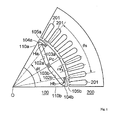
- Fig. 1 is a cross-sectional view showing the configuration of an IPM motor as an embodiment of a permanent magnet-embedded type rotary electric machine according to the invention, which is cut along a plane perpendicular to a rotation axis thereof.
- the IPM motor according to the embodiment includes a six-pole rotor 100 using two permanent magnets 103a and 103b for each pole, and a stator 200 receiving the rotor 100.
- the rotor 100 will be divided into six regions each including two permanent magnets 103a and 103b, and each of these regions will be referred to as a magnetic pole region of the rotor 100 corresponding to one pole.
- Fig. 1 shows the configuration of a magnetic pole region of the rotor 100 corresponding to one pole and a 1/6 region of the stator 200 opposed thereto, in order to prevent the drawing from being complicated.
- the magnetic pole region of the rotor 100 corresponding to one pole is put within a range of an opening angle of 60 degrees between an inter-magnetic pole boundary 110a and an inter-magnetic pole boundary 110b and around a rotation center O of the rotor 100.
- the structure of a region which is counterclockwise (or clockwise) adjacent to the region including the illustrated rotor 100 and the illustrated stator 200 is a structure in which the illustrated rotor 100 corresponding to one pole and the illustrated stator 200 are folded back with respect to the inter-magnetic pole boundary 110a (or 110b).
- the stator 200 has a hollow cylindrical shape.
- a plurality of stator winding slots 201 arrayed at a pitch ⁇ s in a rotation direction of the rotor 100 is formed in an inner circumferential wall of the stator 200.
- fifty-four stator winding slots 201 are formed in the inner circumferential surface of the stator 200.
- nine stator winding slots 201 within an angle range (60 degrees) corresponding to one pole are depicted in Fig. 1 .
- two permanent magnet embedding slits 102a and 102b are formed into a V-shape spreading toward an outer circumferential surface of the rotor 100.
- Permanent magnets 103a and 103b each having a rectangular shape in section are embedded into the permanent magnet embedding slits 102a and 102b. These permanent magnets 103a and 103b turn their magnetic poles with one and the same polarity toward the outer circumferential surface of the rotor 100 so as to form a single magnetic pole in the outer circumferential surface of the rotor 100.
- a center Pc of the magnetic pole is located in a position on a straight line extending from the rotation center O of the rotor 100 and going through a center between the permanent magnets 103a and 103b.
- Magnetic flux short-circuit preventing slits 104a and 104b are formed in the rotor 100.
- the magnetic flux short-circuit preventing slit 104a (or 104b) communicates with, of opposite ends of the magnet embedding slit 102a (or 102b), an end portion closer to the inter-magnetic pole boundary 110a (or 110b), so as to extend toward the center Pc of the magnetic pole.
- the range through which the magnetic flux between the rotor 100 and the stator 200 can pass is limited between and by these magnetic flux short-circuit preventing slits 104a and 104b, so that magnetic flux not going by way of the stator 200 but merely passing through the rotor 100 can be prevented from occurring.
- a pair of grooves 105a and 105b located at a distance from each other symmetrically with respect to a symmetric axis penetrating the center Pc of the magnetic pole are formed in the outer circumferential surface of the rotor 100.
- Each of these grooves 105a and 105b is located at a distance from a groove 105a or 105b (not shown) in an adjacent magnetic pole region.
- angles ⁇ f and ⁇ s are decided to satisfy the following Expressions (1) and (2).
- n 6.
- the region on the outer circumferential surface of the rotor 100 passed through by the magnetic flux from the rotor 100 toward the stator 200 can be limited more completely than when only the magnetic flux short-circuit preventing slits 104a and 104b are provided. Accordingly, it can be expected to reduce cogging torque more stably.
- the design sizes of the angles ⁇ f and ⁇ s are decided in accordance with the following Expressions (3) and (4) in order to reduce cogging torque stably even in a situation where the angles ⁇ f and ⁇ s may be displaced from the design sizes in a real machine.
- n ⁇ ⁇ s - ⁇ ⁇ 1 ⁇ ⁇ f ⁇ n ⁇ ⁇ s + ⁇ ⁇ 2 ⁇ s n ⁇ ⁇ s
- ⁇ 1 and ⁇ 2 designate predetermined constants.
- each of the values of ⁇ 1 and ⁇ 2 is in a range of from 0 to 1 degree.
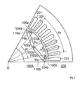
- Fig. 2 is a cross-sectional view showing the configuration of the modification.
- a rotor 100A has an angle ⁇ f displaced from an angle ⁇ s differently from the rotor 100 in Fig. 1 .
- ⁇ s 6.67 degrees
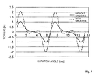
- Fig. 3 is a graph showing the dependency of cogging torque on rotation angle, which dependency is obtained by performing magnetic field analysis on the IPM motor shown in Fig. 1 .
- the abscissa designates a rotation angle of the rotor 100
- the ordinate designates cogging torque occurring in the rotor 100.
- the fluctuation width of the cogging torque from the peak value to the bottom value is 4.1%.
- the fluctuation width of the cogging torque from the peak value to the bottom value is 2.1%.
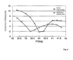
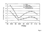
- Fig. 4 is a graph showing the dependency of cogging torque on the angle ⁇ f when the angle ⁇ f is changed while the angle ⁇ s is fixed to 40 degrees in the case where the grooves 105a and 105b are provided in the IPM motor shown in Fig. 2 .
- the abscissa designates the angle ⁇ f
- the ordinate designates the fluctuation width of cogging torque from the peak value to the bottom value when the rotation angle of the rotor 100 is changed. As shown in Fig.
- the fluctuation width of cogging torque in the case where the grooves 105a and 105b are provided becomes larger than that in the case where the grooves 105a and 105b are not provided also as shown in Fig. 3 .
- the fluctuation width of cogging torque in the case where the grooves 105a and 105b are provided becomes stably smaller than that in the case where the grooves 105a and 105b are not provided.
- the magnetic flux short-circuit preventing slits 104a and 104b are provided in the rotor 100, and the pair of grooves 105a and 105b are provided in the outer circumferential surface of the rotor 100.
- the influence of a manufacturing error can be minimized so that cogging torque can be reduced stably.
- the groove 105a (or 105b) is located at a distance from a groove 105b (or 105a) of an adjacent magnetic pole region in the outer circumferential surface of the rotor 100. Accordingly, the magnetic resistance of a magnetic path passing through the inter-magnetic pole region (the region between the magnetic flux short-circuit preventing slit 104a (or 104b) and a magnetic flux short-circuit preventing slit 104b (or 104a) in an adjacent magnetic pole region) of the rotor 100 can be reduced to obtain high reluctance torque.
- the groove 105a (or 105b) is located at a distance from a groove 105b (or 105a) of an adjacent magnetic pole region, the width of the region where the groove 105a (or 105b) faces the magnetic flux short-circuit preventing slit 104a (or 104b) can be narrowed so that a steel plate near the magnetic flux short-circuit preventing slit 104a (or 104b) in the rotor 100 can be prevented from being damaged.
- the limit position of the edge of the groove 105a (or 105b) on the magnetic pole boundary 110a (or 110b) side is set at a position which faces a vertex Ha (or Hb) closer to the outer circumferential surface of the rotor 100 in the permanent magnet 103a (or 103b) and closer to the magnetic pole boundary 110a (or 110b). That is, the position of the edge of the groove 105a (or 105b) on the magnetic pole boundary 110a (or 110b) side is set at a position closer to the center Pc of the magnetic pole than the limit position facing the vertex Ha (or Hb).
- Fig. 5 is a cross-sectional view showing the configuration of an IPM motor as another embodiment of a permanent magnet-embedded type rotary electric machine according to the invention.
- the rotor 100A in Fig. 2 is replaced by a rotor 100B.
- This rotor 100B is different from the rotor 100A in Fig. 2 . That is, the curvature radius of the outer circumferential surface of the rotor 100B is made smaller than the distance between the rotation center O and a point Pc closest to the stator 200 in the outer circumferential surface of the rotor 100B.
- the rotor 100B has a petal shape as a whole.
- Fig. 6 is a graph showing the relationship between the angle ⁇ f and the fluctuation width of cogging torque occurring in the rotor 100B when the angle ⁇ f is changed while the angle ⁇ s is fixed to 40 degrees in the embodiment.
- cogging torque can be further reduced in the petal-shaped rotor 100B as compared with a rotor having a perfectly circular shape.
Landscapes
- Engineering & Computer Science (AREA)
- Power Engineering (AREA)
- Permanent Field Magnets Of Synchronous Machinery (AREA)
- Iron Core Of Rotating Electric Machines (AREA)
- Permanent Magnet Type Synchronous Machine (AREA)
Abstract
Thus, it is possible to provide a permanent magnet-embedded type rotary electric machine in which the influence of manufacturing errors can be minimized so that cogging torque can be reduced.
Description
- The present invention relates to a rotary electric machine with a rotor, such as an electric motor or a power generator. Particularly, it relates to a permanent magnet-embedded type rotary electric machine in which at least one permanent magnet is embedded in a rotor.
- In a permanent magnet-embedded type rotary electric machine, cogging torque occurs when a rotor is rotated even in a non-excited state. The cogging torque should be minimized because the cogging torque is a disturbance in the control of the rotary electric machine. One of measures for reducing the cogging torque is a measure in which an oblique skew is applied to a stator or a stepwise skew is applied to a rotor. However, when this measure is taken, there is a problem that the number of manufacturing steps increases. As a technique for reducing cogging torque without applying any skew to a stator or a rotor, there is, for example, a technique disclosed in
JP-A-2004-343861 JP-A-2004-343861 - The aforementioned background-art permanent magnet-embedded type rotary electric machine has a problem that cogging torque may fluctuate unstably when the dimensions of the slit for limiting the width of the range through which magnetic flux can pass differ from its design dimensions due to the influence of a manufacturing error.
- The invention has been developed in consideration of the aforementioned circumstances. An object of the invention is to provide a permanent magnet-embedded type rotary electric machine in which the influence of a manufacturing error can be minimized so that cogging torque can be reduced stably.
- According to the invention, there is provided a permanent magnet-embedded type rotary electric machine including: a stator which has a plurality of stator winding slots formed in an inner circumferential surface thereof; and a rotor which is rotatably supported so that an outer circumferential surface of the rotor can be opposed to the inner circumferential surface of the stator through a gap, one permanent magnet or a plurality of permanent magnets being embedded in the rotor so as to form a plurality of magnetic poles arrayed in a rotation direction in the outer circumferential surface of the rotor; wherein: magnetic flux short-circuit preventing slits are formed in the rotor so as to extend from opposite ends of the permanent magnet or the permanent magnets forming each of the magnetic poles in the outer circumferential surface of the rotor toward a center of the magnetic pole; and pairs of grooves are formed in the outer circumferential surface of the rotor so that each pair of grooves are located at a distance from each other symmetrically with respect to a symmetry axis passing through the center of corresponding one of the magnetic poles and each of the pair of grooves is located at a distance from a groove of an adjacent magnetic pole in the outer circumferential surface of the rotor.
- According to the invention, due to the magnetic flux short-circuit preventing slits provided in the rotor and the pairs of grooves provided in the outer circumferential surface of the rotor, a range through which magnetic flux can pass between the rotor and the stator is limited properly even in a situation where a manufacturing error occurs. Thus, cogging torque can be reduced stably.
-
-
Fig. 1 is a cross-sectional view showing the configuration of an IPM motor as an embodiment of a permanent magnet-embedded type rotary electric machine according to the invention; -
Fig. 2 is a cross-sectional view showing the configuration of a modification of the IPM motor; -
Fig. 3 is a graph showing the characteristic of cogging torque in the IPM motor according to the embodiment; -
Fig. 4 is a graph showing the characteristic of cogging torque in the IPM motor according to the embodiment; -
Fig. 5 is a cross-sectional view showing the configuration of an IPM motor as another embodiment of a permanent magnet-embedded type rotary electric machine according to the invention; and -
Fig. 6 is a graph showing the characteristic of cogging torque in the IPM motor in the embodiment. - Embodiments of the invention will be described below with reference to the drawings.
-
Fig. 1 is a cross-sectional view showing the configuration of an IPM motor as an embodiment of a permanent magnet-embedded type rotary electric machine according to the invention, which is cut along a plane perpendicular to a rotation axis thereof. The IPM motor according to the embodiment includes a six-pole rotor 100 using twopermanent magnets stator 200 receiving therotor 100. In the following description, for the sake of convenience of explanation, therotor 100 will be divided into six regions each including twopermanent magnets rotor 100 corresponding to one pole. -
Fig. 1 shows the configuration of a magnetic pole region of therotor 100 corresponding to one pole and a 1/6 region of thestator 200 opposed thereto, in order to prevent the drawing from being complicated. As shown inFig. 1 , the magnetic pole region of therotor 100 corresponding to one pole is put within a range of an opening angle of 60 degrees between aninter-magnetic pole boundary 110a and aninter-magnetic pole boundary 110b and around a rotation center O of therotor 100. The structure of a region which is counterclockwise (or clockwise) adjacent to the region including the illustratedrotor 100 and the illustratedstator 200 is a structure in which the illustratedrotor 100 corresponding to one pole and the illustratedstator 200 are folded back with respect to theinter-magnetic pole boundary 110a (or 110b). - The
stator 200 has a hollow cylindrical shape. A plurality ofstator winding slots 201 arrayed at a pitch τs in a rotation direction of therotor 100 is formed in an inner circumferential wall of thestator 200. In this example, fifty-fourstator winding slots 201 are formed in the inner circumferential surface of thestator 200. Accordingly, the pitch τs of thestator winding slots 201 is 360 degrees/54=6. 67 degrees. In addition, ninestator winding slots 201 within an angle range (60 degrees) corresponding to one pole are depicted inFig. 1 . - In the magnetic pole region of the
rotor 100 corresponding to one pole, two permanentmagnet embedding slits rotor 100.Permanent magnets magnet embedding slits permanent magnets rotor 100 so as to form a single magnetic pole in the outer circumferential surface of therotor 100. In this example, in the outer circumferential surface of therotor 100, a center Pc of the magnetic pole is located in a position on a straight line extending from the rotation center O of therotor 100 and going through a center between thepermanent magnets - Magnetic flux short-
circuit preventing slits rotor 100. Here, the magnetic flux short-circuit preventing slit 104a (or 104b) communicates with, of opposite ends of themagnet embedding slit 102a (or 102b), an end portion closer to theinter-magnetic pole boundary 110a (or 110b), so as to extend toward the center Pc of the magnetic pole. The range through which the magnetic flux between therotor 100 and thestator 200 can pass is limited between and by these magnetic flux short-circuit preventing slits stator 200 but merely passing through therotor 100 can be prevented from occurring. - In addition, a pair of
grooves rotor 100. Each of thesegrooves groove - Next, more specific description will be made on the positional relationship between the magnetic flux short-
circuit preventing slits grooves - In this embodiment, when θf designates an angle around the rotation center O of the
rotor 100 put between the two magnetic flux short-circuit preventing slits grooves 

- In the example shown in
Fig. 1 , n=6. In addition, τs=6.67 degrees. Therefore, θf=θs=6×6.67 degrees=40 degrees. - When the magnetic flux short-
circuit preventing slits rotor 100 is introduced to thestator 200 only through a region in a range expressed by θf=n×τs in the outer circumferential surface of therotor 100. As a result, a higher-order component corresponding to the pitch τs of thestator winding slots 201 can be reduced in a rotation-direction magnetic flux density waveform in the outer circumferential surface of therotor 100, so that cogging torque can be reduced. - In addition, when the
grooves rotor 100 passed through by the magnetic flux from therotor 100 toward thestator 200 can be limited more completely than when only the magnetic flux short-circuit preventing slits - It can be considered that the aforementioned angles θf and θs may be displaced from their design sizes in a real machine due to various manufacturing factors. When the aforementioned angles θf and θs are slightly displaced from the design sizes decided in accordance with the aforementioned Expressions (1) and (2), cogging torque may vary unstably.
- Therefore, according to a modification of the embodiment, the design sizes of the angles θf and θs are decided in accordance with the following Expressions (3) and (4) in order to reduce cogging torque stably even in a situation where the angles θf and θs may be displaced from the design sizes in a real machine.


- In the aforementioned Expression (3), Δθ1 and Δθ2 designate predetermined constants. For example, each of the values of Δθ1 and Δθ2 is in a range of from 0 to 1 degree.
-
Fig. 2 is a cross-sectional view showing the configuration of the modification. In this modification, arotor 100A has an angle θf displaced from an angle θs differently from therotor 100 inFig. 1 . Specifically in this modification, τs=6.67 degrees, θs=n×τs=6×6.67 degrees=40 degrees, and θf=n×τs-1=40 degrees-1 degree=39 degrees. - Next, the effect of the embodiment will be described with reference to
Fig. 3 andFig. 4 .Fig. 3 is a graph showing the dependency of cogging torque on rotation angle, which dependency is obtained by performing magnetic field analysis on the IPM motor shown inFig. 1 . InFig. 3 , the abscissa designates a rotation angle of therotor 100, and the ordinate designates cogging torque occurring in therotor 100. When therotor 100 inFig. 1 is rotated as shown inFig. 3 , cogging torque occurring in therotor 100 varies in a period of τs=6.67 degrees. In the configuration in which thegrooves rotor 100 as shown inFig. 1 , the fluctuation width of the cogging torque from the peak value to the bottom value is 4.1%. On the other hand, in the configuration in which thegrooves rotor 100, the fluctuation width of the cogging torque from the peak value to the bottom value is 2.1%. -
Fig. 4 is a graph showing the dependency of cogging torque on the angle θf when the angle θf is changed while the angle θs is fixed to 40 degrees in the case where thegrooves Fig. 2 . InFig. 4 , the abscissa designates the angle θf, and the ordinate designates the fluctuation width of cogging torque from the peak value to the bottom value when the rotation angle of therotor 100 is changed. As shown inFig. 4 , in the condition of θf=θs=40 degrees, the fluctuation width of cogging torque in the case where thegrooves grooves Fig. 3 . However, in the region where the angle θf is displaced from the angle θs=40 degrees, the fluctuation width of cogging torque in the case where thegrooves grooves - According to the embodiment, as described above, the magnetic flux short-
circuit preventing slits rotor 100, and the pair ofgrooves rotor 100. Thus, the influence of a manufacturing error can be minimized so that cogging torque can be reduced stably. - In addition, according to the embodiment, the
groove 105a (or 105b) is located at a distance from agroove 105b (or 105a) of an adjacent magnetic pole region in the outer circumferential surface of therotor 100. Accordingly, the magnetic resistance of a magnetic path passing through the inter-magnetic pole region (the region between the magnetic flux short-circuit preventing slit 104a (or 104b) and a magnetic flux short-circuit preventing slit 104b (or 104a) in an adjacent magnetic pole region) of therotor 100 can be reduced to obtain high reluctance torque. In addition, since thegroove 105a (or 105b) is located at a distance from agroove 105b (or 105a) of an adjacent magnetic pole region, the width of the region where thegroove 105a (or 105b) faces the magnetic flux short-circuit preventing slit 104a (or 104b) can be narrowed so that a steel plate near the magnetic flux short-circuit preventing slit 104a (or 104b) in therotor 100 can be prevented from being damaged. - In consideration of improvement of reluctance torque and prevention of the damage of the steel plate near the magnetic flux short-
circuit preventing slit 104a (or 104b), it is desired not to excessively increase the width of eachgroove rotor 100. To this end, the limit position of the edge of thegroove 105a (or 105b) on themagnetic pole boundary 110a (or 110b) side is set at a position which faces a vertex Ha (or Hb) closer to the outer circumferential surface of therotor 100 in thepermanent magnet 103a (or 103b) and closer to themagnetic pole boundary 110a (or 110b). That is, the position of the edge of thegroove 105a (or 105b) on themagnetic pole boundary 110a (or 110b) side is set at a position closer to the center Pc of the magnetic pole than the limit position facing the vertex Ha (or Hb). -
Fig. 5 is a cross-sectional view showing the configuration of an IPM motor as another embodiment of a permanent magnet-embedded type rotary electric machine according to the invention. In this IPM motor, therotor 100A inFig. 2 is replaced by arotor 100B. Thisrotor 100B is different from therotor 100A inFig. 2 . That is, the curvature radius of the outer circumferential surface of therotor 100B is made smaller than the distance between the rotation center O and a point Pc closest to thestator 200 in the outer circumferential surface of therotor 100B. Thus, therotor 100B has a petal shape as a whole. -
Fig. 6 is a graph showing the relationship between the angle θf and the fluctuation width of cogging torque occurring in therotor 100B when the angle θf is changed while the angle θs is fixed to 40 degrees in the embodiment. As is understood from comparison withFig. 4 , cogging torque can be further reduced in the petal-shapedrotor 100B as compared with a rotor having a perfectly circular shape. - Although the embodiments of the invention have been described above, other embodiments may be conceived in the invention, for example, as follows.
- (1) Although two permanent magnets for each pole are disposed in a V-shape in a rotor and grooves each having a rectangular shape in section are formed in an outer circumferential surface of the rotor in the aforementioned embodiments, the number of permanent magnets constituting each pole, the layout of the permanent magnets and the shape of each groove are not limited thereto.
- (2) Although the belt-like magnetic flux short-
circuit preventing slits circuit preventing slit
Claims (5)
- A permanent magnet-embedded type rotary electric machine comprising: a stator which has a plurality of stator winding slots formed in an inner circumferential surface thereof; and a rotor which is rotatably supported so that an outer circumferential surface of the rotor can be opposed to the inner circumferential surface of the stator through a gap, one permanent magnet or a plurality of permanent magnets being embedded in the rotor so as to form a plurality of magnetic poles arrayed in a rotation direction in the outer circumferential surface of the rotor; wherein:magnetic flux short-circuit preventing slits are formed in the rotor so as to extend from opposite ends of the permanent magnet or the permanent magnets forming each of the magnetic poles in the outer circumferential surface of the rotor toward a center of the magnetic pole; andpairs of grooves are formed in the outer circumferential surface of the rotor so that each pair of grooves are located at a distance from each other symmetrically with respect to a symmetry axis passing through the center of corresponding one of the magnetic poles and each of the pair of grooves is located at a distance from a groove of an adjacent magnetic pole in the outer circumferential surface of the rotor.
- The permanent magnet-embedded type rotary electric machine according to Claim 1, wherein this machine is arranged and designed such that the following relations are fulfilled:


where τs designates a pitch of the stator winding slots which pitch is converted into an angle around a rotation center of the rotor, θf designates an angle around the rotation center of the rotor put between two magnetic flux short-circuit preventing slits, θs designates an angle around the rotation center of the rotor put between the pair of grooves, and n designates a predetermined integer. - The permanent magnet-embedded type rotary electric machine according to Claim 1, wherein this machine is arranged and designed such that the following relations are fulfilled:


where τs designates a pitch of the stator winding slots which pitch is converted into an angle around a rotation center of the rotor, θf designates an angle around the rotation center of the rotor put between two magnetic flux short-circuit preventing slits, θs designates an angle around the rotation center of the rotor put between the pair of grooves, n designates a predetermined integer, and Δθ1 and Δθ2 designate predetermined angles. - The permanent magnet-embedded type rotary electric machine according to any one of Claims 1 through 3, wherein: an outer circumferential shape of the rotor excluding portions of the grooves is a perfectly circular shape.
- The permanent magnet-embedded type rotary electric machine according to any one of Claims 1 through 3, wherein: a curvature radius of the outer circumferential surface of the rotor is smaller than a distance between a point on the outer circumferential surface of the rotor closest to the stator and the rotation center of the rotor, and the rotor has a petal shape.
Applications Claiming Priority (1)
| Application Number | Priority Date | Filing Date | Title |
|---|---|---|---|
| JP2013182266A JP6379462B2 (en) | 2013-09-03 | 2013-09-03 | Permanent magnet embedded rotary electric machine |
Publications (2)
| Publication Number | Publication Date |
|---|---|
| EP2843804A2 true EP2843804A2 (en) | 2015-03-04 |
| EP2843804A3 EP2843804A3 (en) | 2016-03-16 |
Family
ID=51300633
Family Applications (1)
| Application Number | Title | Priority Date | Filing Date |
|---|---|---|---|
| EP14180593.7A Withdrawn EP2843804A3 (en) | 2013-09-03 | 2014-08-12 | Permanent magnet-embedded type rotary electric machine |
Country Status (4)
| Country | Link |
|---|---|
| US (1) | US10396609B2 (en) |
| EP (1) | EP2843804A3 (en) |
| JP (1) | JP6379462B2 (en) |
| CN (1) | CN104426267B (en) |
Families Citing this family (14)
| Publication number | Priority date | Publication date | Assignee | Title |
|---|---|---|---|---|
| JP2017050965A (en) * | 2015-09-01 | 2017-03-09 | 日産自動車株式会社 | Rotor structure of rotating electrical machine |
| JP6768672B2 (en) * | 2015-09-04 | 2020-10-14 | 日立オートモティブシステムズ株式会社 | Rotor of rotary electric machine, rotary electric machine, and vehicle |
| JP2017070040A (en) * | 2015-09-29 | 2017-04-06 | アイシン精機株式会社 | Three-phase rotary electric machine |
| JP6806352B2 (en) * | 2015-10-13 | 2021-01-06 | 株式会社安川電機 | Manufacturing method of rotary electric machine and rotor core |
| KR20170050079A (en) * | 2015-10-29 | 2017-05-11 | (주)지이엠 | Motor With Notched Rotor For Cogging Torque Reduction |
| US10523072B2 (en) | 2016-06-15 | 2019-12-31 | Ford Global Technologies, Llc | Electric machine rotor |
| DE102017103619A1 (en) * | 2017-02-22 | 2018-08-23 | Ebm-Papst St. Georgen Gmbh & Co. Kg | Electric motor, inner rotor and rotor plate |
| CN108462263B (en) * | 2018-03-29 | 2024-04-30 | 广东美芝制冷设备有限公司 | Motors, compressors and refrigeration equipment |
| CN109038890B (en) * | 2018-07-31 | 2020-01-14 | 珠海格力电器股份有限公司 | Electric machine |
| KR102654530B1 (en) * | 2018-12-27 | 2024-04-03 | 현대자동차주식회사 | Interior permanent magnet motor and rotator including thereof |
| CN111769670A (en) * | 2020-07-16 | 2020-10-13 | 精进电动科技股份有限公司 | Rotor iron core and permanent magnet synchronous motor of a segmented inclined pole motor |
| CN115989622A (en) * | 2020-08-31 | 2023-04-18 | 日本电产株式会社 | rotating electrical machine |
| US11646617B2 (en) * | 2021-08-30 | 2023-05-09 | Hiwin Mikrosystem Corp. | High-frequency rotating structure with permanent magnet rotor having grooves and magnetic barrier spaces |
| JP7679791B2 (en) * | 2022-03-30 | 2025-05-20 | 株式会社豊田自動織機 | Rotating electric machine and manufacturing method thereof |
Citations (3)
| Publication number | Priority date | Publication date | Assignee | Title |
|---|---|---|---|---|
| JP2004343861A (en) | 2003-05-14 | 2004-12-02 | Matsushita Electric Ind Co Ltd | Permanent magnet synchronous motor |
| EP1965484A1 (en) * | 2005-12-19 | 2008-09-03 | Daikin Industries, Ltd. | Electric motor and its rotor, and magnetic core for the rotor |
| JP2013099193A (en) * | 2011-11-04 | 2013-05-20 | Suzuki Motor Corp | Electric rotary machine |
Family Cites Families (36)
| Publication number | Priority date | Publication date | Assignee | Title |
|---|---|---|---|---|
| US5508576A (en) * | 1990-07-12 | 1996-04-16 | Seiko Epson Corporation | Rotor for brushless electromotor |
| US6133662A (en) * | 1996-09-13 | 2000-10-17 | Hitachi, Ltd. | Permanent magnet dynamoelectric rotating machine and electric vehicle equipped with the same |
| JP3746372B2 (en) * | 1998-04-16 | 2006-02-15 | 株式会社日立製作所 | Permanent magnet type rotating electric machine and electric vehicle using the same |
| US6486581B2 (en) * | 2000-03-31 | 2002-11-26 | Sanyo Denki Co., Ltd. | Interior permanent magnet synchronous motor |
| US6917133B2 (en) * | 2000-08-29 | 2005-07-12 | Hitachi, Ltd. | Air conditioner having permanent magnet rotating electric machine |
| JP3787756B2 (en) * | 2000-08-29 | 2006-06-21 | 株式会社日立製作所 | Permanent magnet rotating electric machine |
| TW538578B (en) * | 2000-09-13 | 2003-06-21 | Sanyo Electric Co | Synchronous motor with built-in type permanent magnet |
| ITTO20010182A1 (en) * | 2001-03-02 | 2002-09-02 | Fiat Ricerche | SYNCHRONOUS TYPE ELECTRIC MACHINE. |
| JP2002354727A (en) * | 2001-05-21 | 2002-12-06 | Hitachi Ltd | Rotor and rotating electric machine with permanent magnet embedded |
| US6867526B2 (en) * | 2001-09-05 | 2005-03-15 | Koyo Seiko Co., Ltd. | Brushless DC motor |
| US7230359B2 (en) * | 2002-03-22 | 2007-06-12 | Ebm-Papst St. Georgen Gmbh & Co. Kg | Electric motor with poles shaped to minimize cogging torque |
| JP3811426B2 (en) * | 2002-05-15 | 2006-08-23 | 株式会社日立製作所 | Permanent magnet rotating electric machine |
| JP4314816B2 (en) * | 2002-11-28 | 2009-08-19 | ダイキン工業株式会社 | Brushless DC motor and brushless DC motor control device |
| DE202004016534U1 (en) * | 2003-11-05 | 2005-01-05 | Ebm-Papst St. Georgen Gmbh & Co. Kg | electric motor |
| JP4311182B2 (en) * | 2003-12-08 | 2009-08-12 | 日産自動車株式会社 | Rotating electric machine rotor |
| JP3638944B1 (en) * | 2004-02-04 | 2005-04-13 | 山洋電気株式会社 | Method for determining pole arc ratio of rotary motor with built-in permanent magnet and rotary motor with built-in permanent magnet |
| JP4449035B2 (en) * | 2004-03-10 | 2010-04-14 | 日立オートモティブシステムズ株式会社 | Permanent magnet rotating electric machine for electric vehicles |
| JP2005354798A (en) * | 2004-06-10 | 2005-12-22 | Fujitsu General Ltd | Electric motor |
| JP4815204B2 (en) * | 2005-12-01 | 2011-11-16 | アイチエレック株式会社 | Permanent magnet rotating machine and compressor |
| JP4898201B2 (en) * | 2005-12-01 | 2012-03-14 | アイチエレック株式会社 | Permanent magnet rotating machine |
| JP4793027B2 (en) * | 2006-02-28 | 2011-10-12 | 株式会社豊田自動織機 | Permanent magnet embedded rotary electric machine, motor for car air conditioner and hermetic electric compressor |
| US7683518B2 (en) * | 2007-02-28 | 2010-03-23 | Panasonic Corporation | Motor |
| US8405270B2 (en) * | 2007-05-07 | 2013-03-26 | Panasonic Corporation | Permanent magnet buried type electric motor |
| JP4708448B2 (en) * | 2008-03-04 | 2011-06-22 | 日立オートモティブシステムズ株式会社 | Rotating electric machines and electric vehicles |
| JP5433198B2 (en) * | 2008-10-16 | 2014-03-05 | 日立オートモティブシステムズ株式会社 | Rotating electric machines and electric vehicles |
| KR101526206B1 (en) * | 2008-12-15 | 2015-06-05 | 엘지전자 주식회사 | Permanent magnet embedded type BDDC motor |
| US8179011B2 (en) * | 2008-12-17 | 2012-05-15 | Asmo Co., Ltd. | Brushless motor |
| KR101578424B1 (en) * | 2009-02-05 | 2015-12-17 | 엘지전자 주식회사 | Permanent magnet inserting type BD motor and compressor equipped therewith |
| JP5434415B2 (en) * | 2009-09-14 | 2014-03-05 | 株式会社豊田自動織機 | Permanent magnet embedded rotary electric machine |
| JP2011083164A (en) * | 2009-10-09 | 2011-04-21 | Mitsubishi Electric Corp | Rotor of permanent magnet type motor |
| DE102011107803B4 (en) * | 2010-07-21 | 2025-02-27 | Denso Corporation | MOTOR |
| JP5413358B2 (en) * | 2010-12-07 | 2014-02-12 | 株式会社安川電機 | Electric motor |
| JP5948061B2 (en) * | 2012-01-19 | 2016-07-06 | 日立オートモティブシステムズ株式会社 | Rotating electric machine and vehicle equipped with the rotating electric machine |
| WO2014068655A1 (en) * | 2012-10-30 | 2014-05-08 | 三菱電機株式会社 | Electric motor with embedded permanent magnet, and refrigeration and air conditioning equipment equipped with same |
| US9985484B2 (en) * | 2015-06-09 | 2018-05-29 | Ford Global Technologies, Llc | Surface groove patterns for permanent magnet machine rotors |
| JP6654902B2 (en) * | 2016-01-07 | 2020-02-26 | Ntn株式会社 | Rotary motor |
-
2013
- 2013-09-03 JP JP2013182266A patent/JP6379462B2/en active Active
-
2014
- 2014-08-11 CN CN201410391832.0A patent/CN104426267B/en active Active
- 2014-08-12 EP EP14180593.7A patent/EP2843804A3/en not_active Withdrawn
- 2014-08-12 US US14/457,774 patent/US10396609B2/en active Active
Patent Citations (3)
| Publication number | Priority date | Publication date | Assignee | Title |
|---|---|---|---|---|
| JP2004343861A (en) | 2003-05-14 | 2004-12-02 | Matsushita Electric Ind Co Ltd | Permanent magnet synchronous motor |
| EP1965484A1 (en) * | 2005-12-19 | 2008-09-03 | Daikin Industries, Ltd. | Electric motor and its rotor, and magnetic core for the rotor |
| JP2013099193A (en) * | 2011-11-04 | 2013-05-20 | Suzuki Motor Corp | Electric rotary machine |
Also Published As
| Publication number | Publication date |
|---|---|
| JP2015050874A (en) | 2015-03-16 |
| EP2843804A3 (en) | 2016-03-16 |
| CN104426267B (en) | 2018-09-04 |
| CN104426267A (en) | 2015-03-18 |
| US20150061447A1 (en) | 2015-03-05 |
| JP6379462B2 (en) | 2018-08-29 |
| US10396609B2 (en) | 2019-08-27 |
Similar Documents
| Publication | Publication Date | Title |
|---|---|---|
| US10396609B2 (en) | Permanent magnet-embedded type rotary electric machine with rotor having slots and rotor surface grooves | |
| DE112014000526B4 (en) | Rotor and rotating electrical machine containing this rotor | |
| US10594177B2 (en) | Rotary electric machine and rotor core manufacturing method | |
| CN108462269B (en) | Motor rotor | |
| EP2961044B1 (en) | Motor and its permanent magnet rotor | |
| CN107528397B (en) | Motor rotor | |
| US10707707B2 (en) | Electric machine rotor | |
| EP2463988A2 (en) | Electric motor | |
| JP5811565B2 (en) | Rotor and permanent magnet motor | |
| EP3300231B1 (en) | Electric machine | |
| EP1261103B1 (en) | Brushless dc motor | |
| JP6667665B2 (en) | Rotating electric machine rotor and method of manufacturing rotor for rotating electric machine | |
| US10714994B2 (en) | Rotor and rotary electric machine | |
| EP2602912A2 (en) | Brushless motor | |
| US20190181705A1 (en) | Rotor and method for designing rotor | |
| CN112425036A (en) | Rotating electrical machine | |
| CN112567597B (en) | Rotating motor | |
| KR101525222B1 (en) | Interior Permanent Magnet Synchronous Machine | |
| EP4443705A1 (en) | Rotating electric machine | |
| JP2016226218A (en) | Permanent magnet embedded rotor for rotary electric machine | |
| EP4191835A1 (en) | Rotor of interior permanent magnet synchronous motor | |
| KR20190073595A (en) | Rotors & Rotors | |
| US9692263B2 (en) | Stator core for rotary electric machine |
Legal Events
| Date | Code | Title | Description |
|---|---|---|---|
| 17P | Request for examination filed |
Effective date: 20140812 |
|
| AK | Designated contracting states |
Kind code of ref document: A2 Designated state(s): AL AT BE BG CH CY CZ DE DK EE ES FI FR GB GR HR HU IE IS IT LI LT LU LV MC MK MT NL NO PL PT RO RS SE SI SK SM TR |
|
| AX | Request for extension of the european patent |
Extension state: BA ME |
|
| PUAI | Public reference made under article 153(3) epc to a published international application that has entered the european phase |
Free format text: ORIGINAL CODE: 0009012 |
|
| PUAL | Search report despatched |
Free format text: ORIGINAL CODE: 0009013 |
|
| AK | Designated contracting states |
Kind code of ref document: A3 Designated state(s): AL AT BE BG CH CY CZ DE DK EE ES FI FR GB GR HR HU IE IS IT LI LT LU LV MC MK MT NL NO PL PT RO RS SE SI SK SM TR |
|
| AX | Request for extension of the european patent |
Extension state: BA ME |
|
| RIC1 | Information provided on ipc code assigned before grant |
Ipc: H02K 1/27 20060101AFI20160208BHEP Ipc: H02K 29/03 20060101ALI20160208BHEP |
|
| R17P | Request for examination filed (corrected) |
Effective date: 20160913 |
|
| RBV | Designated contracting states (corrected) |
Designated state(s): AL AT BE BG CH CY CZ DE DK EE ES FI FR GB GR HR HU IE IS IT LI LT LU LV MC MK MT NL NO PL PT RO RS SE SI SK SM TR |
|
| STAA | Information on the status of an ep patent application or granted ep patent |
Free format text: STATUS: EXAMINATION IS IN PROGRESS |
|
| 17Q | First examination report despatched |
Effective date: 20200128 |
|
| REG | Reference to a national code |
Ref country code: DE Ref legal event code: R079 Free format text: PREVIOUS MAIN CLASS: H02K0001270000 Ipc: H02K0001276000 |
|
| GRAP | Despatch of communication of intention to grant a patent |
Free format text: ORIGINAL CODE: EPIDOSNIGR1 |
|
| STAA | Information on the status of an ep patent application or granted ep patent |
Free format text: STATUS: GRANT OF PATENT IS INTENDED |
|
| RIC1 | Information provided on ipc code assigned before grant |
Ipc: H02K 29/03 20060101ALI20220421BHEP Ipc: H02K 1/276 20220101AFI20220421BHEP |
|
| INTG | Intention to grant announced |
Effective date: 20220510 |
|
| STAA | Information on the status of an ep patent application or granted ep patent |
Free format text: STATUS: THE APPLICATION IS DEEMED TO BE WITHDRAWN |
|
| 18D | Application deemed to be withdrawn |
Effective date: 20220921 |