EP2843750A2 - Rechargeable battery pack - Google Patents
Rechargeable battery pack Download PDFInfo
- Publication number
- EP2843750A2 EP2843750A2 EP14162798.4A EP14162798A EP2843750A2 EP 2843750 A2 EP2843750 A2 EP 2843750A2 EP 14162798 A EP14162798 A EP 14162798A EP 2843750 A2 EP2843750 A2 EP 2843750A2
- Authority
- EP
- European Patent Office
- Prior art keywords
- rechargeable battery
- battery pack
- frame
- pack according
- battery cell
- Prior art date
- Legal status (The legal status is an assumption and is not a legal conclusion. Google has not performed a legal analysis and makes no representation as to the accuracy of the status listed.)
- Granted
Links
Images


Classifications
-
- H—ELECTRICITY
- H01—ELECTRIC ELEMENTS
- H01M—PROCESSES OR MEANS, e.g. BATTERIES, FOR THE DIRECT CONVERSION OF CHEMICAL ENERGY INTO ELECTRICAL ENERGY
- H01M50/00—Constructional details or processes of manufacture of the non-active parts of electrochemical cells other than fuel cells, e.g. hybrid cells
- H01M50/10—Primary casings, jackets or wrappings of a single cell or a single battery
- H01M50/102—Primary casings, jackets or wrappings of a single cell or a single battery characterised by their shape or physical structure
-
- H—ELECTRICITY
- H01—ELECTRIC ELEMENTS
- H01M—PROCESSES OR MEANS, e.g. BATTERIES, FOR THE DIRECT CONVERSION OF CHEMICAL ENERGY INTO ELECTRICAL ENERGY
- H01M10/00—Secondary cells; Manufacture thereof
- H01M10/42—Methods or arrangements for servicing or maintenance of secondary cells or secondary half-cells
- H01M10/425—Structural combination with electronic components, e.g. electronic circuits integrated to the outside of the casing
-
- H—ELECTRICITY
- H01—ELECTRIC ELEMENTS
- H01M—PROCESSES OR MEANS, e.g. BATTERIES, FOR THE DIRECT CONVERSION OF CHEMICAL ENERGY INTO ELECTRICAL ENERGY
- H01M50/00—Constructional details or processes of manufacture of the non-active parts of electrochemical cells other than fuel cells, e.g. hybrid cells
- H01M50/10—Primary casings, jackets or wrappings of a single cell or a single battery
- H01M50/172—Arrangements of electric connectors penetrating the casing
-
- H—ELECTRICITY
- H01—ELECTRIC ELEMENTS
- H01M—PROCESSES OR MEANS, e.g. BATTERIES, FOR THE DIRECT CONVERSION OF CHEMICAL ENERGY INTO ELECTRICAL ENERGY
- H01M50/00—Constructional details or processes of manufacture of the non-active parts of electrochemical cells other than fuel cells, e.g. hybrid cells
- H01M50/20—Mountings; Secondary casings or frames; Racks, modules or packs; Suspension devices; Shock absorbers; Transport or carrying devices; Holders
-
- H—ELECTRICITY
- H01—ELECTRIC ELEMENTS
- H01M—PROCESSES OR MEANS, e.g. BATTERIES, FOR THE DIRECT CONVERSION OF CHEMICAL ENERGY INTO ELECTRICAL ENERGY
- H01M50/00—Constructional details or processes of manufacture of the non-active parts of electrochemical cells other than fuel cells, e.g. hybrid cells
- H01M50/50—Current conducting connections for cells or batteries
- H01M50/531—Electrode connections inside a battery casing
-
- H—ELECTRICITY
- H01—ELECTRIC ELEMENTS
- H01M—PROCESSES OR MEANS, e.g. BATTERIES, FOR THE DIRECT CONVERSION OF CHEMICAL ENERGY INTO ELECTRICAL ENERGY
- H01M50/00—Constructional details or processes of manufacture of the non-active parts of electrochemical cells other than fuel cells, e.g. hybrid cells
- H01M50/50—Current conducting connections for cells or batteries
- H01M50/572—Means for preventing undesired use or discharge
- H01M50/574—Devices or arrangements for the interruption of current
-
- Y—GENERAL TAGGING OF NEW TECHNOLOGICAL DEVELOPMENTS; GENERAL TAGGING OF CROSS-SECTIONAL TECHNOLOGIES SPANNING OVER SEVERAL SECTIONS OF THE IPC; TECHNICAL SUBJECTS COVERED BY FORMER USPC CROSS-REFERENCE ART COLLECTIONS [XRACs] AND DIGESTS
- Y02—TECHNOLOGIES OR APPLICATIONS FOR MITIGATION OR ADAPTATION AGAINST CLIMATE CHANGE
- Y02E—REDUCTION OF GREENHOUSE GAS [GHG] EMISSIONS, RELATED TO ENERGY GENERATION, TRANSMISSION OR DISTRIBUTION
- Y02E60/00—Enabling technologies; Technologies with a potential or indirect contribution to GHG emissions mitigation
- Y02E60/10—Energy storage using batteries
-
- Y—GENERAL TAGGING OF NEW TECHNOLOGICAL DEVELOPMENTS; GENERAL TAGGING OF CROSS-SECTIONAL TECHNOLOGIES SPANNING OVER SEVERAL SECTIONS OF THE IPC; TECHNICAL SUBJECTS COVERED BY FORMER USPC CROSS-REFERENCE ART COLLECTIONS [XRACs] AND DIGESTS
- Y02—TECHNOLOGIES OR APPLICATIONS FOR MITIGATION OR ADAPTATION AGAINST CLIMATE CHANGE
- Y02P—CLIMATE CHANGE MITIGATION TECHNOLOGIES IN THE PRODUCTION OR PROCESSING OF GOODS
- Y02P70/00—Climate change mitigation technologies in the production process for final industrial or consumer products
- Y02P70/50—Manufacturing or production processes characterised by the final manufactured product
Definitions
- the present invention relates to a rechargeable battery pack, for example a tablet type rechargeable battery pack.
- a rechargeable battery is a battery that can be repeatedly charged and discharged, unlike a primary battery.
- a low-capacity rechargeable battery is used for small portable electronic devices such as a mobile phone, a tablet computer, a notebook computer, and a camcorder and a large-capacity rechargeable battery is used as a power supply for driving a motor such as an electric bike, a scooter, an electric vehicle, a fork lift and the like.
- the rechargeable battery may be used in a unit battery cell or a pack state in which a plurality of unit battery cells are electrically connected to each other according to a kind of the used device.
- a rechargeable battery pack may include a plurality of unit battery cells, a protection circuit module (PCM) electrically connecting and protecting the plurality of unit battery cells and a frame receiving the plurality of unit cells and the PCM.
- PCM protection circuit module
- the rechargeable battery pack used in the tablet computer may be configured to receive the unit battery cell in the frame and to attach the unit battery cell and the frame using a label.
- the rechargeable battery pack is used in a state in which strength required according to a drop test is not considered and is not separated from the tablet computer by a user.
- the rechargeable battery pack may be separated from the tablet computer by the user.
- the rechargeable battery pack needs the strength required according to the drop test.
- the present invention has been made to address the above problem and some embodiments of the invention provide a rechargeable battery pack formed of a tablet type and having strength required according to a drop test.
- An exemplary embodiment of the present invention provides a rechargeable battery pack, including: a unit battery cell formed of a tablet type rechargeable battery; a frame enclosing the unit battery cell; a protective circuit module electrically connected to the unit battery cell to embedded in the frame; and a pair of cases protecting the unit battery cell and the protective circuit module by coupling with both sides of the frame.
- the circuit installation part may include a through hole formed at a portion corresponding to a lead tab of the unit battery cell; a position limit protrusion protruded from one side of the through hole to predetermine a position of the lead tab and supporting the protective circuit module; and a circuit supporting protrusion having a height higher than that of the position limit protrusion on the edge of the circuit installation part and supporting the side of the protective circuit module.
- the frame may further include an opening part formed on one side of the circuit installation part so that a connector of the protective circuit module is positioned at the outside of the frame.
- the frame may include an insertion groove continuously formed at both sides of the frame so that the outer wall of the case is inserted thereinto, and a coupling groove penetrated through from the insertion groove into the outside of the frame.
- the coupling grooves may be symmetrically disposed to each other in the frame so as to corresponding to the pair of cases.
- the case may include a plate part corresponding to both surfaces of the frame and the unit battery cell; an insertion part bent downwardly in the plate part to thereby insert into the insertion groove; an extension part having a width that becomes narrow downwardly in the insertion part; and a coupling protrusion protruded from the extension part to thereby couple to the coupling groove.
- the coupling protrusion is formed by cutting the one side and press processing three sides in the extension part.
- the coupling protrusion may include a pair of side walls vertically connected with the extension part, an inclined wall that inclinedly connects the side walls in the extension part; and a connecting wall of which the side walls are connected in parallel with the extension part in the inclined wall.
- the side walls, the connecting wall and a cutout line may be a rectangle.
- the connecting wall corresponds to width of the coupling groove, such that the side wall may be closely adhered on the inner side wall of the coupling groove.
- the coupling protrusion is formed by cutting the one side and press processing three sides in the extension part.
- the coupling protrusion may include the pair of side walls inclinedly connected with the extension part, the inclined wall that inclinedly connects the side walls in the extension part; and the connecting wall of which the side walls are connected in parallel with the extension part in the inclined wall.
- the side walls, the connecting wall and the cutout line are formed in a rectangle, and the connecting wall has a width narrow than that of the coupling groove, such that the side walls may be spaced apart from the inner side wall of the coupling groove.
- the coupling protrusion is formed by cutting in a protrusions and depressions structure and press processing three sides in the extension part.
- the coupling protrusion may include the pair of side walls inclinedly connected with the extension part, the inclined wall that inclinedly connects the side walls in the extension part; and the connecting wall of which the side walls are connected in parallel with the extension part in the inclined wall and the cutout line has the protrusions and depressions structure.
- the rechargeable battery pack encloses the tablet type unit battery cell with the frame and has a pair of cases coupled with both sides of the frame to protect the unit battery cell and the protective circuit module embedded therein. That is, the rechargeable battery pack is formed of the tablet type and has the unit battery cell and the protect circuit module embedded in the frame and the case, thereby making it possible to have a strength required according to the drop test.
- the rechargeable battery pack may be separated from the tablet computer by the user.
- FIG. 1 is an exploded perspective view of a rechargeable battery pack 100 according to the first exemplary embodiment of the present invention.
- the rechargeable battery pack 100 according to the first exemplary embodiment includes a unit battery cell 10 formed of a rechargeable battery, a frame 20 enclosing the unit battery cell 10, a protectively circuit module 30 (see FIG. 3 ), and a pair of cases 41 and 42.
- the frame 20 encloses the unit battery cell 10. In other embodiments, the frame 20 may be arranged to at least partially surround side surfaces of the battery cell 10.
- the rechargeable battery pack 100 includes the two unit battery cells 10, but it may include one or more unit battery cells 10.
- the unit battery cell 10 is formed of a tablet type rechargeable battery in this embodiment, but embodiments of the invention are not limited thereto.
- the frame 20 encloses the outer side of the thin unit battery cell 10, and the pair of cases 41 and 42 covers a wide upper and lower surfaces of the unit battery cell 10.
- the frame 20 is made of a synthetic resin material
- the pair of cases 41 and 42 is made of a metal material, for example, stainless steel.
- the protective circuit module 30 is electrically connected to the unit battery cell 10 to protect the unit battery cells 10.
- the unit battery cell 10 and the protect circuit module 30 may be protected from the external impact by the pair of cases 41 and 42 and the frame 20.
- the protective circuit module 30 is formed to mount a circuit element on a printed circuit board so that the unit battery cells 10 may be protected from overcharge, over-discharge, overcurrent and external short.
- the case 41 and 42 is coupled with an opening formed in both surfaces of the frame 20 to protect the unit battery cells 10 and the protective circuit module 30, and includes an insulating tape (not shown) on inner surface thereof, to thereby improve the electric insulating property of the unit battery cells 10 and the protective circuit module 30.
- the insulating tape protects the unit battery cell 10 from the external impact, thereby making it possible to further improve stability.
- FIG. 2 is an exploded perspective view of the unit battery cell 10 used in FIG. 1 .
- the unit battery cell 10 is formed of a pouch type rechargeable battery, and includes an electrode assembly 11 in which charging and discharging are performed and a pouch 12 having the electrode assembly 11 embedded therein.
- the electrode assembly 11 is prepared by disposing and winding a positive electrode 14 and a negative electrode 15 having a separator 13 therebetween, to form a tablet type.
- the separator 13 may be formed of a polymer film that transmits lithium-ion.
- the positive electrode 14 includes a coating region formed by applying an active material to a current collector of the metal thin film and an uncoated region formed as a current collector exposed by not applying the active material.
- the positive electrode 14 may be formed of an aluminum thin film.
- a positive electrode lead tab 16 is connected to the uncoated region of the positive electrode 14.
- the negative electrode 15 includes a coating region formed by applying an active material which is different from the active material of the positive electrode 14 to the current collector of the metal thin film and an uncoated region formed as the current collector exposed by not applying the active material.
- the negative electrode 15 may be formed of a copper thin film.
- a negative electrode lead tab 17 is spaced apart from the positive electrode lead tab 16 and is connected to the uncoated region of the negative electrode 15.
- the pouch 12 has one side formed in a concave structure and the other side formed in a planar structure so as to enclose the outside of the electrode assembly 11, and the edge facing in a state in which they are connected to each other at the one side is joined to each other by heat-fusion, such that the pouch 12 may receive the electrode assembly 11.
- the pouch 12 is formed in a multi-layered sheet structure.
- the pouch 12 may be formed the polymer sheet 121 forming the inner surface of the pouch and performing the heat-fusion, polyethyleneterephthalate (PET) sheet forming the outer surface thereof to protect the electrode assembly 11, a nylon sheet or PET-nylon composite sheet 122.
- PET polyethyleneterephthalate
- the pouch 12 is provided between the polymer sheet 121 and the PET-nylon composite sheet 122 and includes a metal sheet 123 providing the mechanical strength.
- the metal sheet 123 may be formed of an aluminum sheet.
- the positive electrode lead tab 16 and the negative electrode lead tab 17 are drawn out to the same side of the electrode assembly 11. Since the positive electrode lead tab 16 and the negative electrode lead tab 17 are protruded outward of the heat-fused pouch 12, the electrode assembly 11 may be electrically connected to an outer portion of the pouch 12.
- insulating members 161 and 162 cover the positive and negative electrode lead tabs 16 and 17 on the pouch 12, respectively to electrically insulate the positive and negative electrode lead tabs 16 and 17 from the pouch 12 to thereby improve the electric insulating property of the positive and negative electrode lead tabs 16 and 17.
- FIG. 3 is a partial exploded perspective view of the frame 20, the unit battery cell 10 and the protective circuit module 30 shown in FIG. 1 .
- the two unit battery cells 10 that face each other are disposed.
- the frame 20 encloses the two unit battery cells 10 and includes a circuit installation part 21 provided on one side of a portion at which the two unit battery cells 10 face each other. That is, the circuit installation part 21 is provided at one side in a z-axis direction in a central portion of the frame 20 in an x-axis direction.
- the circuit installation part 21 is arranged to support the protective circuit module 30.
- the protective circuit module 30 may be installed on the circuit installation part 21 in a state in which it is electrically connected to the two unit battery cells 10. That is, the circuit installation part 21 is joined with the protective circuit module 30 in the z-axis direction.
- the frame 20 may be arranged to at least partially surround side surfaces of both battery cells 10, and the circuit installation part 21 may be arranged between the two battery cells 10.
- the circuit installation part 21 includes a through hole 211, a position limit protrusion 212 and a circuit supporting protrusion 213.
- the through hole 211 is formed at the portion corresponding to each of the positive and negative electrode lead tab 16 and 17 of the two unit battery cells 10 and welding machine (not shown) may approach the through hole 211, such that the positive and negative electrode lead tabs 16 and 17 may be welded to a welding part 32 of the protective circuit module 30.
- the case 42 includes a through hole H (see FIG. 1 ) corresponding to the through hold 211 and the welding part 32, such that the welding machine may approach through the through holes H and 211 in the state in which the frame 20 is installed in the case 42.
- the position limit protrusion 212 opens the one side of the through hole 211 and is protruded in three directions to thereby predetermine the position the positive and negative electrode lead tabs 16 and 17 disposed on the one side opened and to support the protective circuit module 30. Since the position limit protrusion 212 is protruded from the bottom surface of the circuit installation part 21, the position of the positive and negative electrode lead tabs 16 and 17 is predetermined when the unit battery cell 10 is disposed on the frame 20 in order to weld the positive and negative electrode lead tabs 16 and 17. In addition, since the position limit protrusion 212 is protruded from the bottom surface, thereby preventing a circuit portion of the protective circuit module 30 from being contacted with the positive and negative electrode lead tabs 16 and 17.
- the circuit supporting protrusion 213 is disposed on the edge diagonally across on the circuit installation part 21 in a diagonal direction (that is, attached to the upper surface of the circuit installation part 21 and the inner side wall of the frame 20) and is protrudedly formed to have a height higher than that of the position limit protrusion 212 to support the side surface of the protective circuit module 30. That is, the protective circuit module 30 has the position of a plane (xy plane) set by the circuit supporting protrusion 213 and the position in the z-axis direction set by the position limit protrusion 212. Therefore, the protective circuit module 30 may be stably installed to the circuit installation part 21 and may be supported.
- the protective circuit module 30 includes the connector 31 at one side thereof and draws out the connector 31 to the outside of the frame 20, to thereby supply a power to load for the set.
- the frame 20 is provided with the opening part 22 formed at one side of the circuit installation part 21.
- the connector 31 of the protective circuit module 30 may be disposed to the outside of the frame 20 through the opening part 22.
- the catching protrusion 214 is provided on inner side of the opening part 22 to support the rear of the connector 31 inserted into the opening part 22, such that the protective circuit module 30 is maintained in a state in which it is stably installed.
- FIG. 4 is a top plan view of the frame 20 used in FIG. 1 and FIG. 5 is a side view of the frame 20 used in FIG. 4 .
- the frame 20 includes an insertion groove 24 and 25 continuously formed at both sides of the frame so that the outer wall of a pair of cases 41 and 42 is inserted thereinto, and the coupling groove 26 and 27 penetrated through from the insertion groove 24 and 25 into the outside of the frame 20.
- the coupling groove 26 and 27 are symmetrically disposed to each other in the frame 20 in the z-axis direction so as to corresponding to each of the pair of cases 41 and 42. Therefore, the pair of cases 41 and 42 is symmetrically formed to each other corresponding to the coupling groove 26 and 27.
- FIG. 6 is a partial perspective view showing a state in which a pair of cases 41 and 42 is separated from the frame 20.
- the pair of cases 41 and 42 includes a plate part 411 and 421, an insertion part 412 and 422, an extension part 413 and 423 and a coupling protrusion 414 and 424 so that it is coupled with the frame 20 to receive the unit battery cell 10.
- the plate part 411 and 421 is formed in a plate shape to correspond to the both surfaces of the unit battery cell 10 and the frame 20 and covers the both surfaces of the unit battery cell 10 and the frame 20 in the z-axis direction.
- the insertion part 412 and 422 is bended at a perpendicular angle to the plate part 411 and 421 and is inserted into an insertion groove 24 and 25 formed in the both surfaces of the frame 20 in the z-axis direction.
- a plurality of extension parts 413 and 423 is disposed to correspond to the insertion groove 24 and 25 along the insertion part 412 and 422. Further, the plurality of extension parts 413 and 423 are extended in a width that becomes narrow downwardly in the insertion part 412 and 422 and may be disposed to be opposite to each of the coupling grooves 26 and 27 in the insertion grooves 24 and 25 (see FIG. 9 ).
- the coupling protrusions 414 and 424 are protruded from the extension parts 413 and 423 in the y-axis (or x-axis) direction and may be connected to each of the coupling grooves 26 and 27(see FIG. 9 ).
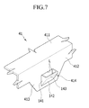
- FIG. 7 is a partial enlarged perspective view of a coupling protrusion 414 of a case 41.
- the coupling protrusions 414 and 424 are formed in the same shape, for convenience, the coupling protrusion 414 will be described as an example.
- the coupling protrusion 414 is formed on the extension part 413 so that it is inserted into the insertion groove 24 to couple with the coupling groove 26 and is formed in a three-dimensional structure including a pair of side walls 141, an inclined wall 142 and a connecting wall 143.
- the pair of side walls 141 is vertically connected to the extension part 413 in both ends of the cutout line L by cutting the one side and press processing the cutout line L and the remaining three sides in the extension part 413.
- the inclined wall 142 is inclinedly connected to the pair of side walls 141 in the opposite side extension part 413 for the cutout line L. Therefore, the inclined wall 142 effectively leads the coupling protrusion 414 inserted into the insertion groove 24.
- the connecting wall 143 connects between the side walls 141 in the inclined wall 142 and maintains a state in which it is disposed in parallel with the extension part 413.
- the end of the connecting wall 143 formed in the cutout line L and end of the side wall 141 are formed to have opened structure at an opposite side of the inclined wall 142 to couple with the coupling groove 26. Accordingly, the coupling protrusion 414 may maintain joint force for the frame 20 in the z-axis direction.
- the coupling part (protrusion) 414 is arranged to taper such that it protrudes less in the insertion direction.
- the coupling part 414 comprises two opposite side walls 141 that protrude from the extension part (portion) 413, the two opposite side walls 141 tapering from a first end of the coupling part 414 to a second end of the coupling protrusion 414 in the insertion direction.
- the connecting wall 143 connects the two opposite side walls 141.
- the two opposite side walls 141 and the connecting wall 143 define an opening that faces away from the insertion direction.
- FIG. 8 is a partial side view showing a state in which a pair of cases 41 and 42 is coupled with the frame 20 and
- FIG. 9 is a cross-sectional view taken along line IX-IX in FIG. 8 Referring to FIGS. 8 and 9 , the side wall 141, the connecting wall 143 and the cutout line L in the coupling protrusion 414 are formed in the rectangle.
- the connecting wall 143 corresponds to the width W of the coupling groove 26 and the side wall 141 provided on both sides of the connecting wall 143 is closely adhered to the inner side wall of the coupling groove 26.
- the case 41 may prevent flow in the frame 20 in the x-axis direction.
- the coupling protrusion 424 is coupled to the coupling groove 27 in the same structure as the coupling protrusion 414.
- FIG. 10 is a partial side view showing a state in which a pair of cases 241 and 242 is coupled with a frame 20 in a rechargeable battery pack 200 according to the second exemplary embodiment of the present invention
- FIG. 11 is a partial enlarged perspective view of a coupling protrusion 243 of the case 241 used in FIG. 10 .
- the coupling protrusion 243 is formed in the three-dimensional structure including the pair of side walls 431, the inclined wall 432 and the connecting wall 433.
- the pair of side walls 431 is inclined connected to the extension part 413 in both ends of the cutout line L by cutting the one side and press processing the cutout line L and the remaining three sides from the extension part 413. That is, the side wall 431 is inclined with an angle of inclination ⁇ of the side wall 141 according to the first exemplary embodiment.
- the inclined wall 432 is inclinedly connected to the pair of side walls 431 in the opposite side extension part 413 for the cutout line L. Therefore, the side wall 431 and the inclined wall 432 effectively leads the coupling protrusion 243 inserted into the insertion groove 24.
- the connecting wall 433 connects between the side walls 141 in the inclined wall 432 and maintains a state in which it is disposed in parallel with the extension part 413.
- the end of the connecting wall 433 formed in the cutout line L and end of the side wall 431 are formed to have opened structure at an opposite side of the inclined wall 432 to couple with the coupling groove 26. Accordingly, the coupling protrusion 243 may maintain joint force for the frame 20 in the z-axis direction.
- the side wall 431, the connecting wall 433, and the cutout line L are formed in the rectangle. If the case 241 is coupled to the frame 20, the coupling protrusion 243 is coupled with the coupling groove 26.
- the connecting wall 433 has a width W1 narrow than the width W of the coupling groove 26, and the side wall 431 provided in the both sides of the connecting wall 433 is spaced apart from the inner side wall of the coupling groove 26. Therefore, if the case 241 is coupled to the frame 20, the coupling protrusion 243 may be easily coupled with the coupling groove 26.
- FIG. 12 is a partial side view showing a state in which a pair of cases 341 and 342 is coupled with a frame 20 in a rechargeable battery pack 300 according to the third exemplary embodiment of the present invention
- FIG. 13 is a partial enlarged perspective view of a coupling protrusion 343 of the case 341 used in FIG. 12 .
- the coupling protrusion 414, 424, and 243 according to the first and second exemplary embodiments has the cutout line L formed in a straight line and the coupling protrusion 343 according to the third exemplary embodiment has the cutout line L3 formed in a protrusions and depressions structure.
- the coupling protrusion 343 is formed in the three-dimensional structure including the pair of side walls 341, the inclined wall 342 and the connecting wall 343.
- the pair of side walls 341 is inclinedly connected to the extension part 413 in both ends of the cutout line L3 by cutting the one side in a protrusions and depressions structure and press processing the cutout line L3 and the remaining three sides from the extension part 413.
- the inclined wall 342 is inclinedly connected to the pair of side walls 341 in the opposite side extension part 413 for the cutout line L3. Therefore, the side wall 341 and the inclined wall 342 effectively leads the coupling protrusion 343 inserted into the insertion groove 24.
- the connecting wall 343 connects between the side walls 341 in the inclined wall 342 and maintains a state in which it is disposed in parallel with the extension part 413.
- the end of the connecting wall 343 formed in the cutout line L3 and end of the side wall 341 are formed to have opened structure at an opposite side of the inclined wall 342 to couple with the coupling groove 26.
- the connecting wall 434 and the side wall 341 has the protrusions and depressions structure corresponding to the cutout line L3 forming the opening structure.
- the coupling protrusion 343 of the metal material is coupled with the coupling groove 26 of the synthetic resin material
- the protrusions and depressions structure of the connecting wall 434 and the side wall 341 is press-fitted into the coupling groove 26 of the frame 20.
- the ends of two opposite side walls 314 and the connecting wall 434 that face away from the insertion direction form a series of protrusions and depressions. Therefore, the coupling protrusion 343 may maintain a strong joint force for the frame 20 in the x-and z-axes directions.
- a rechargeable battery pack comprising: a battery cell; a protective circuit module electrically connected to the battery cell; a frame arranged to at least partially surround side surfaces of the battery cell, wherein the frame comprises a circuit installation part arranged to support the protective circuit module; a first case and a second case arranged to receive the battery cell and to be coupled to the frame.
- the circuit installation part may be arranged at a side region of the battery cell.
- the battery cell may be relatively thin with two major surfaces separated by relatively short side surfaces, and the circuit installation part may be arranged in a plane parallel to the major surfaces.
- the protective circuit module may be generally planar, and hence the protective circuit module may be supported at a side region of the battery cell, with the protective circuit module arranged in a plane parallel to the major surfaces of the battery cell.
- the rechargeable battery pack is a tablet type rechargeable battery pack.
- the rechargeable battery pack comprises two battery cells, and the frame is arranged to at least partially surround side surfaces of both battery cells, and the circuit installation part is arranged between the two battery cells.
- the frame comprises a side wall adjacent a side surface of the battery cell, wherein the side wall comprises a first insertion groove at a first end of the side wall, and wherein an insertion part of the first case is arranged to be received in the first insertion groove to couple the first case to the frame.
- the insertion part of the first case comprises an engagement part for engagement with a corresponding engagement part of the side wall.
- the insertion part of the first case comprises an extension portion arranged to extend in an insertion direction towards the first end of the side wall, and a coupling protrusion arranged to protrude from the extension portion; and the side wall comprises a coupling groove arranged to receive the coupling protrusion.
- the coupling protrusion may be arranged to taper such that it protrudes less in the insertion direction.
- the coupling protrusion may comprise: two opposite side walls that protrude from the extension portion, the two opposite side walls tapering from a first end of the coupling protrusion to a second end of the coupling protrusion in the insertion direction; and a connecting wall arranged to connect the two opposite side walls.
- the two opposite side walls and the connecting wall may define an opening that faces away from the insertion direction.
- the ends of two opposite side walls and the connecting wall that face away from the insertion direction may form a series of protrusions and depressions.
- the width of coupling protrusion is equal to the width of the coupling groove.
- the insertion part of the first case comprises a plurality of said extension portions and coupling protrusions for respective engagement with a plurality of corresponding coupling grooves of the side wall.
- the side wall comprises a second insertion groove at a second end of the side wall opposite the first end, and wherein an insertion part of the second case is arranged to be received in the second insertion groove to couple the second case to the frame.
- the insertion part of the second case may comprise an extension portion arranged to extend in a second case insertion direction towards the second end of the side wall, and a coupling protrusion arranged to protrude from the extension portion.
- the side wall may comprise a coupling groove arranged to receive the coupling protrusion.
- the protective circuit module is electrically connected to first and second electrode tabs of the battery cell, and the circuit installation part may comprises through holes to enable welding of the first and second electrode tabs of the battery cell to the protective circuit module during manufacture.
- the circuit installation part comprises positioning protrusions arranged to respectively position the first and second electrode tabs of the battery cell.
- the circuit installation part comprises a supporting protrusion arranged to support a side of the protective circuit module.
- the rechargeable battery pack further comprises a connector arranged to connect the protective circuit module to an external device via an opening in the frame.
- the circuit installation part may comprise a connector protrusion arranged to support the connector.
Abstract
Description
- The present invention relates to a rechargeable battery pack, for example a tablet type rechargeable battery pack.
- A rechargeable battery is a battery that can be repeatedly charged and discharged, unlike a primary battery. A low-capacity rechargeable battery is used for small portable electronic devices such as a mobile phone, a tablet computer, a notebook computer, and a camcorder and a large-capacity rechargeable battery is used as a power supply for driving a motor such as an electric bike, a scooter, an electric vehicle, a fork lift and the like.
- The rechargeable battery may be used in a unit battery cell or a pack state in which a plurality of unit battery cells are electrically connected to each other according to a kind of the used device. For example, a rechargeable battery pack may include a plurality of unit battery cells, a protection circuit module (PCM) electrically connecting and protecting the plurality of unit battery cells and a frame receiving the plurality of unit cells and the PCM.
- For example, the rechargeable battery pack used in the tablet computer may be configured to receive the unit battery cell in the frame and to attach the unit battery cell and the frame using a label. In this case, the rechargeable battery pack is used in a state in which strength required according to a drop test is not considered and is not separated from the tablet computer by a user.
- However, the rechargeable battery pack may be separated from the tablet computer by the user. In this case, the rechargeable battery pack needs the strength required according to the drop test.
- The above information disclosed in this Background section is only for enhancement of understanding of the background of the invention and therefore it may contain information that does not form the prior art that is already known in this country to a person of ordinary skill in the art.
- The present invention has been made to address the above problem and some embodiments of the invention provide a rechargeable battery pack formed of a tablet type and having strength required according to a drop test.
- An exemplary embodiment of the present invention provides a rechargeable battery pack, including: a unit battery cell formed of a tablet type rechargeable battery; a frame enclosing the unit battery cell; a protective circuit module electrically connected to the unit battery cell to embedded in the frame; and a pair of cases protecting the unit battery cell and the protective circuit module by coupling with both sides of the frame.
- The circuit installation part may include a through hole formed at a portion corresponding to a lead tab of the unit battery cell; a position limit protrusion protruded from one side of the through hole to predetermine a position of the lead tab and supporting the protective circuit module; and a circuit supporting protrusion having a height higher than that of the position limit protrusion on the edge of the circuit installation part and supporting the side of the protective circuit module.
- The frame may further include an opening part formed on one side of the circuit installation part so that a connector of the protective circuit module is positioned at the outside of the frame.
- The frame may include an insertion groove continuously formed at both sides of the frame so that the outer wall of the case is inserted thereinto, and a coupling groove penetrated through from the insertion groove into the outside of the frame.
- The coupling grooves may be symmetrically disposed to each other in the frame so as to corresponding to the pair of cases. The case may include a plate part corresponding to both surfaces of the frame and the unit battery cell; an insertion part bent downwardly in the plate part to thereby insert into the insertion groove; an extension part having a width that becomes narrow downwardly in the insertion part; and a coupling protrusion protruded from the extension part to thereby couple to the coupling groove.
- The coupling protrusion is formed by cutting the one side and press processing three sides in the extension part. In addition, the coupling protrusion may include a pair of side walls vertically connected with the extension part, an inclined wall that inclinedly connects the side walls in the extension part; and a connecting wall of which the side walls are connected in parallel with the extension part in the inclined wall.
- The side walls, the connecting wall and a cutout line may be a rectangle.
- The connecting wall corresponds to width of the coupling groove, such that the side wall may be closely adhered on the inner side wall of the coupling groove.
- The coupling protrusion is formed by cutting the one side and press processing three sides in the extension part. In addition, the coupling protrusion may include the pair of side walls inclinedly connected with the extension part, the inclined wall that inclinedly connects the side walls in the extension part; and the connecting wall of which the side walls are connected in parallel with the extension part in the inclined wall.
- The side walls, the connecting wall and the cutout line are formed in a rectangle, and the connecting wall has a width narrow than that of the coupling groove, such that the side walls may be spaced apart from the inner side wall of the coupling groove.
- The coupling protrusion is formed by cutting in a protrusions and depressions structure and press processing three sides in the extension part. In addition, the coupling protrusion may include the pair of side walls inclinedly connected with the extension part, the inclined wall that inclinedly connects the side walls in the extension part; and the connecting wall of which the side walls are connected in parallel with the extension part in the inclined wall and the cutout line has the protrusions and depressions structure.
- According to an aspect of the invention, there is provided a rechargeable battery pack according to claim 1. Preferred features of this aspect are set out in claims 2 to 15.
- As described above, the rechargeable battery pack according to an exemplary embodiment of the present invention encloses the tablet type unit battery cell with the frame and has a pair of cases coupled with both sides of the frame to protect the unit battery cell and the protective circuit module embedded therein. That is, the rechargeable battery pack is formed of the tablet type and has the unit battery cell and the protect circuit module embedded in the frame and the case, thereby making it possible to have a strength required according to the drop test. In addition, the rechargeable battery pack may be separated from the tablet computer by the user.
-
FIG. 1 is an exploded perspective view of a rechargeable battery pack according to the first exemplary embodiment of the present invention. -
FIG. 2 is an exploded perspective view of a unit battery cell used inFIG. 1 . -
FIG. 3 is a partial exploded perspective view of the frame, the unit battery cell and the protective circuit module shown inFIG. 1 . -
FIG. 4 is a top plan view of the frame used inFIG. 1 .FIG. 5 is a side view of the frame used inFIG. 4 . -
FIG. 6 is a partial perspective view showing a state in which a pair of cases is separated from the frame. -
FIG. 7 is a partial enlarged perspective view of a coupling protrusion of a case. -
FIG. 8 is a partial side view showing a state in which a pair of cases is coupled with the frame. -
FIG. 9 is a cross-sectional view taken along line IX-IX inFIG. 8 . -
FIG. 10 is a partial side view showing a state in which a pair of cases is coupled with a frame in a rechargeable battery pack according to the second exemplary embodiment of the present invention. -
FIG. 11 is a partial enlarged perspective view of a coupling protrusion of the case used inFIG. 10 . -
FIG. 12 is a partial side view showing a state in which a pair of cases is coupled with a frame in a rechargeable battery pack according to the third exemplary embodiment of the present invention. -
FIG. 13 is a partial enlarged perspective view of a coupling protrusion of the case used inFIG. 12 . - The present invention will be described more fully hereinafter with reference to the accompanying drawings, in which exemplary embodiments of the invention are shown. As those skilled in the art would realize, the described embodiments may be modified in various different ways, all without departing from the scope of the present invention. The drawings and description are to be regarded as illustrative in nature and not restrictive. Like reference numerals designate like elements throughout the specification.
-
FIG. 1 is an exploded perspective view of arechargeable battery pack 100 according to the first exemplary embodiment of the present invention. Referring toFIG. 1 , therechargeable battery pack 100 according to the first exemplary embodiment includes aunit battery cell 10 formed of a rechargeable battery, aframe 20 enclosing theunit battery cell 10, a protectively circuit module 30 (seeFIG. 3 ), and a pair ofcases - In this embodiment, the
frame 20 encloses theunit battery cell 10. In other embodiments, theframe 20 may be arranged to at least partially surround side surfaces of thebattery cell 10. - The
rechargeable battery pack 100 according to the first exemplary embodiment includes the twounit battery cells 10, but it may include one or moreunit battery cells 10. Theunit battery cell 10 is formed of a tablet type rechargeable battery in this embodiment, but embodiments of the invention are not limited thereto. - The
frame 20 encloses the outer side of the thinunit battery cell 10, and the pair ofcases unit battery cell 10. For example, theframe 20 is made of a synthetic resin material, and the pair ofcases - Here, the
protective circuit module 30 is electrically connected to theunit battery cell 10 to protect theunit battery cells 10. In addition, theunit battery cell 10 and theprotect circuit module 30 may be protected from the external impact by the pair ofcases frame 20. Theprotective circuit module 30 is formed to mount a circuit element on a printed circuit board so that theunit battery cells 10 may be protected from overcharge, over-discharge, overcurrent and external short. - The
case frame 20 to protect theunit battery cells 10 and theprotective circuit module 30, and includes an insulating tape (not shown) on inner surface thereof, to thereby improve the electric insulating property of theunit battery cells 10 and theprotective circuit module 30. In addition, the insulating tape protects theunit battery cell 10 from the external impact, thereby making it possible to further improve stability. -
FIG. 2 is an exploded perspective view of theunit battery cell 10 used inFIG. 1 . Referring toFIG. 2 , theunit battery cell 10 is formed of a pouch type rechargeable battery, and includes anelectrode assembly 11 in which charging and discharging are performed and apouch 12 having theelectrode assembly 11 embedded therein. - In this embodiment, the
electrode assembly 11 is prepared by disposing and winding apositive electrode 14 and anegative electrode 15 having aseparator 13 therebetween, to form a tablet type. As an example, theseparator 13 may be formed of a polymer film that transmits lithium-ion. - In this embodiment, the
positive electrode 14 includes a coating region formed by applying an active material to a current collector of the metal thin film and an uncoated region formed as a current collector exposed by not applying the active material. For example, thepositive electrode 14 may be formed of an aluminum thin film. A positiveelectrode lead tab 16 is connected to the uncoated region of thepositive electrode 14. - In this embodiment, the
negative electrode 15 includes a coating region formed by applying an active material which is different from the active material of thepositive electrode 14 to the current collector of the metal thin film and an uncoated region formed as the current collector exposed by not applying the active material. For example, thenegative electrode 15 may be formed of a copper thin film. A negativeelectrode lead tab 17 is spaced apart from the positiveelectrode lead tab 16 and is connected to the uncoated region of thenegative electrode 15. - In this embodiment, the
pouch 12 has one side formed in a concave structure and the other side formed in a planar structure so as to enclose the outside of theelectrode assembly 11, and the edge facing in a state in which they are connected to each other at the one side is joined to each other by heat-fusion, such that thepouch 12 may receive theelectrode assembly 11. - In this embodiment, the
pouch 12 is formed in a multi-layered sheet structure. For example, thepouch 12 may be formed thepolymer sheet 121 forming the inner surface of the pouch and performing the heat-fusion, polyethyleneterephthalate (PET) sheet forming the outer surface thereof to protect theelectrode assembly 11, a nylon sheet or PET-nylon composite sheet 122. - As an example, the
pouch 12 is provided between thepolymer sheet 121 and the PET-nylon composite sheet 122 and includes ametal sheet 123 providing the mechanical strength. For example, themetal sheet 123 may be formed of an aluminum sheet. - In this embodiment, the positive
electrode lead tab 16 and the negativeelectrode lead tab 17 are drawn out to the same side of theelectrode assembly 11. Since the positiveelectrode lead tab 16 and the negativeelectrode lead tab 17 are protruded outward of the heat-fusedpouch 12, theelectrode assembly 11 may be electrically connected to an outer portion of thepouch 12. - Here, insulating
members electrode lead tabs pouch 12, respectively to electrically insulate the positive and negativeelectrode lead tabs pouch 12 to thereby improve the electric insulating property of the positive and negativeelectrode lead tabs -
FIG. 3 is a partial exploded perspective view of theframe 20, theunit battery cell 10 and theprotective circuit module 30 shown inFIG. 1 . Referring toFIGS. 1 and3 , in therechargeable battery pack 100, the twounit battery cells 10 that face each other are disposed. - In this embodiment, the
frame 20 encloses the twounit battery cells 10 and includes acircuit installation part 21 provided on one side of a portion at which the twounit battery cells 10 face each other. That is, thecircuit installation part 21 is provided at one side in a z-axis direction in a central portion of theframe 20 in an x-axis direction. Thecircuit installation part 21 is arranged to support theprotective circuit module 30. - Therefore, the
protective circuit module 30 may be installed on thecircuit installation part 21 in a state in which it is electrically connected to the twounit battery cells 10. That is, thecircuit installation part 21 is joined with theprotective circuit module 30 in the z-axis direction. - For embodiments, which comprise two
battery cells 10, theframe 20 may be arranged to at least partially surround side surfaces of bothbattery cells 10, and thecircuit installation part 21 may be arranged between the twobattery cells 10. - In detail, in this embodiment, the
circuit installation part 21 includes a throughhole 211, aposition limit protrusion 212 and acircuit supporting protrusion 213. The throughhole 211 is formed at the portion corresponding to each of the positive and negativeelectrode lead tab unit battery cells 10 and welding machine (not shown) may approach the throughhole 211, such that the positive and negativeelectrode lead tabs welding part 32 of theprotective circuit module 30. - In addition the
case 42 includes a through hole H (seeFIG. 1 ) corresponding to the throughhold 211 and thewelding part 32, such that the welding machine may approach through the through holes H and 211 in the state in which theframe 20 is installed in thecase 42. - The
position limit protrusion 212 opens the one side of the throughhole 211 and is protruded in three directions to thereby predetermine the position the positive and negativeelectrode lead tabs protective circuit module 30. Since theposition limit protrusion 212 is protruded from the bottom surface of thecircuit installation part 21, the position of the positive and negativeelectrode lead tabs unit battery cell 10 is disposed on theframe 20 in order to weld the positive and negativeelectrode lead tabs position limit protrusion 212 is protruded from the bottom surface, thereby preventing a circuit portion of theprotective circuit module 30 from being contacted with the positive and negativeelectrode lead tabs - The
circuit supporting protrusion 213 is disposed on the edge diagonally across on thecircuit installation part 21 in a diagonal direction (that is, attached to the upper surface of thecircuit installation part 21 and the inner side wall of the frame 20) and is protrudedly formed to have a height higher than that of theposition limit protrusion 212 to support the side surface of theprotective circuit module 30. That is, theprotective circuit module 30 has the position of a plane (xy plane) set by thecircuit supporting protrusion 213 and the position in the z-axis direction set by theposition limit protrusion 212. Therefore, theprotective circuit module 30 may be stably installed to thecircuit installation part 21 and may be supported. - The
protective circuit module 30 includes theconnector 31 at one side thereof and draws out theconnector 31 to the outside of theframe 20, to thereby supply a power to load for the set. For this purpose, theframe 20 is provided with the openingpart 22 formed at one side of thecircuit installation part 21. Theconnector 31 of theprotective circuit module 30 may be disposed to the outside of theframe 20 through the openingpart 22. The catchingprotrusion 214 is provided on inner side of theopening part 22 to support the rear of theconnector 31 inserted into theopening part 22, such that theprotective circuit module 30 is maintained in a state in which it is stably installed. -
FIG. 4 is a top plan view of theframe 20 used inFIG. 1 andFIG. 5 is a side view of theframe 20 used inFIG. 4 . Referring toFIGS. 4 and5 , theframe 20 includes aninsertion groove cases coupling groove insertion groove frame 20. - The
coupling groove frame 20 in the z-axis direction so as to corresponding to each of the pair ofcases cases coupling groove -
FIG. 6 is a partial perspective view showing a state in which a pair ofcases frame 20. Referring toFIG. 6 , the pair ofcases plate part insertion part extension part coupling protrusion frame 20 to receive theunit battery cell 10. - The
plate part unit battery cell 10 and theframe 20 and covers the both surfaces of theunit battery cell 10 and theframe 20 in the z-axis direction. Theinsertion part plate part insertion groove frame 20 in the z-axis direction. - A plurality of
extension parts insertion groove insertion part extension parts insertion part coupling grooves insertion grooves 24 and 25 (seeFIG. 9 ). The coupling protrusions 414 and 424 are protruded from theextension parts coupling grooves 26 and 27(seeFIG. 9 ). -
FIG. 7 is a partial enlarged perspective view of acoupling protrusion 414 of acase 41. The coupling protrusions 414 and 424 are formed in the same shape, for convenience, thecoupling protrusion 414 will be described as an example. - Referring to
FIG. 7 , thecoupling protrusion 414 is formed on theextension part 413 so that it is inserted into theinsertion groove 24 to couple with thecoupling groove 26 and is formed in a three-dimensional structure including a pair ofside walls 141, aninclined wall 142 and a connectingwall 143. - The pair of
side walls 141 is vertically connected to theextension part 413 in both ends of the cutout line L by cutting the one side and press processing the cutout line L and the remaining three sides in theextension part 413. - The
inclined wall 142 is inclinedly connected to the pair ofside walls 141 in the oppositeside extension part 413 for the cutout line L. Therefore, theinclined wall 142 effectively leads thecoupling protrusion 414 inserted into theinsertion groove 24. - The connecting
wall 143 connects between theside walls 141 in theinclined wall 142 and maintains a state in which it is disposed in parallel with theextension part 413. In addition, the end of the connectingwall 143 formed in the cutout line L and end of theside wall 141 are formed to have opened structure at an opposite side of theinclined wall 142 to couple with thecoupling groove 26. Accordingly, thecoupling protrusion 414 may maintain joint force for theframe 20 in the z-axis direction. - Hence, in this embodiment, the coupling part (protrusion) 414 is arranged to taper such that it protrudes less in the insertion direction. In this embodiment, the
coupling part 414 comprises twoopposite side walls 141 that protrude from the extension part (portion) 413, the twoopposite side walls 141 tapering from a first end of thecoupling part 414 to a second end of thecoupling protrusion 414 in the insertion direction. The connectingwall 143 connects the twoopposite side walls 141. The twoopposite side walls 141 and the connectingwall 143 define an opening that faces away from the insertion direction. -
FIG. 8 is a partial side view showing a state in which a pair ofcases frame 20 andFIG. 9 is a cross-sectional view taken along line IX-IX inFIG. 8 Referring toFIGS. 8 and9 , theside wall 141, the connectingwall 143 and the cutout line L in thecoupling protrusion 414 are formed in the rectangle. - If the
case 41 is coupled to theframe 20, thecoupling protrusion 414 is coupled to thecoupling groove 26, in this case, the connectingwall 143 corresponds to the width W of thecoupling groove 26 and theside wall 141 provided on both sides of the connectingwall 143 is closely adhered to the inner side wall of thecoupling groove 26. - Therefore, the
case 41 may prevent flow in theframe 20 in the x-axis direction. Although not described, if thecase 42 is coupled to theframe 20, thecoupling protrusion 424 is coupled to thecoupling groove 27 in the same structure as thecoupling protrusion 414. -
FIG. 10 is a partial side view showing a state in which a pair ofcases frame 20 in arechargeable battery pack 200 according to the second exemplary embodiment of the present invention andFIG. 11 is a partial enlarged perspective view of acoupling protrusion 243 of thecase 241 used inFIG. 10 . - Referring to
FIGS. 10 and11 , thecoupling protrusion 243 is formed in the three-dimensional structure including the pair ofside walls 431, theinclined wall 432 and the connectingwall 433. - The pair of
side walls 431 is inclined connected to theextension part 413 in both ends of the cutout line L by cutting the one side and press processing the cutout line L and the remaining three sides from theextension part 413. That is, theside wall 431 is inclined with an angle of inclination θ of theside wall 141 according to the first exemplary embodiment. - The
inclined wall 432 is inclinedly connected to the pair ofside walls 431 in the oppositeside extension part 413 for the cutout line L. Therefore, theside wall 431 and theinclined wall 432 effectively leads thecoupling protrusion 243 inserted into theinsertion groove 24. - The connecting
wall 433 connects between theside walls 141 in theinclined wall 432 and maintains a state in which it is disposed in parallel with theextension part 413. In addition, the end of the connectingwall 433 formed in the cutout line L and end of theside wall 431 are formed to have opened structure at an opposite side of theinclined wall 432 to couple with thecoupling groove 26. Accordingly, thecoupling protrusion 243 may maintain joint force for theframe 20 in the z-axis direction. - The
side wall 431, the connectingwall 433, and the cutout line L are formed in the rectangle. If thecase 241 is coupled to theframe 20, thecoupling protrusion 243 is coupled with thecoupling groove 26. Here, the connectingwall 433 has a width W1 narrow than the width W of thecoupling groove 26, and theside wall 431 provided in the both sides of the connectingwall 433 is spaced apart from the inner side wall of thecoupling groove 26. Therefore, if thecase 241 is coupled to theframe 20, thecoupling protrusion 243 may be easily coupled with thecoupling groove 26. -
FIG. 12 is a partial side view showing a state in which a pair ofcases frame 20 in arechargeable battery pack 300 according to the third exemplary embodiment of the present invention andFIG. 13 is a partial enlarged perspective view of acoupling protrusion 343 of thecase 341 used inFIG. 12 . - The
coupling protrusion coupling protrusion 343 according to the third exemplary embodiment has the cutout line L3 formed in a protrusions and depressions structure. - Referring to
FIGS. 12 and13 , thecoupling protrusion 343 is formed in the three-dimensional structure including the pair ofside walls 341, theinclined wall 342 and the connectingwall 343. - The pair of
side walls 341 is inclinedly connected to theextension part 413 in both ends of the cutout line L3 by cutting the one side in a protrusions and depressions structure and press processing the cutout line L3 and the remaining three sides from theextension part 413. - The
inclined wall 342 is inclinedly connected to the pair ofside walls 341 in the oppositeside extension part 413 for the cutout line L3. Therefore, theside wall 341 and theinclined wall 342 effectively leads thecoupling protrusion 343 inserted into theinsertion groove 24. - The connecting
wall 343 connects between theside walls 341 in theinclined wall 342 and maintains a state in which it is disposed in parallel with theextension part 413. In addition, the end of the connectingwall 343 formed in the cutout line L3 and end of theside wall 341 are formed to have opened structure at an opposite side of theinclined wall 342 to couple with thecoupling groove 26. - In this case, the connecting
wall 434 and theside wall 341 has the protrusions and depressions structure corresponding to the cutout line L3 forming the opening structure. In the state in which thecoupling protrusion 343 of the metal material is coupled with thecoupling groove 26 of the synthetic resin material, the protrusions and depressions structure of the connectingwall 434 and theside wall 341 is press-fitted into thecoupling groove 26 of theframe 20. Hence, in this embodiment, the ends of two opposite side walls 314 and the connectingwall 434 that face away from the insertion direction form a series of protrusions and depressions. Therefore, thecoupling protrusion 343 may maintain a strong joint force for theframe 20 in the x-and z-axes directions. - As discussed, embodiments of the invention provide a rechargeable battery pack comprising: a battery cell; a protective circuit module electrically connected to the battery cell; a frame arranged to at least partially surround side surfaces of the battery cell, wherein the frame comprises a circuit installation part arranged to support the protective circuit module; a first case and a second case arranged to receive the battery cell and to be coupled to the frame.
- In some embodiments, the circuit installation part may be arranged at a side region of the battery cell. In some such embodiments, the battery cell may be relatively thin with two major surfaces separated by relatively short side surfaces, and the circuit installation part may be arranged in a plane parallel to the major surfaces. The protective circuit module may be generally planar, and hence the protective circuit module may be supported at a side region of the battery cell, with the protective circuit module arranged in a plane parallel to the major surfaces of the battery cell.
- In some embodiments, the rechargeable battery pack is a tablet type rechargeable battery pack.
- In some embodiments, the rechargeable battery pack comprises two battery cells, and the frame is arranged to at least partially surround side surfaces of both battery cells, and the circuit installation part is arranged between the two battery cells.
- In some embodiments, the frame comprises a side wall adjacent a side surface of the battery cell, wherein the side wall comprises a first insertion groove at a first end of the side wall, and wherein an insertion part of the first case is arranged to be received in the first insertion groove to couple the first case to the frame.
- In some embodiments, the insertion part of the first case comprises an engagement part for engagement with a corresponding engagement part of the side wall.
- In some embodiments, the insertion part of the first case comprises an extension portion arranged to extend in an insertion direction towards the first end of the side wall, and a coupling protrusion arranged to protrude from the extension portion; and the side wall comprises a coupling groove arranged to receive the coupling protrusion. In such embodiments, the coupling protrusion may be arranged to taper such that it protrudes less in the insertion direction. In such embodiments, the coupling protrusion may comprise: two opposite side walls that protrude from the extension portion, the two opposite side walls tapering from a first end of the coupling protrusion to a second end of the coupling protrusion in the insertion direction; and a connecting wall arranged to connect the two opposite side walls. The two opposite side walls and the connecting wall may define an opening that faces away from the insertion direction. In such embodiments, the ends of two opposite side walls and the connecting wall that face away from the insertion direction may form a series of protrusions and depressions.
- In some embodiments, the width of coupling protrusion is equal to the width of the coupling groove.
- In some embodiments, the insertion part of the first case comprises a plurality of said extension portions and coupling protrusions for respective engagement with a plurality of corresponding coupling grooves of the side wall.
- In some embodiments, the side wall comprises a second insertion groove at a second end of the side wall opposite the first end, and wherein an insertion part of the second case is arranged to be received in the second insertion groove to couple the second case to the frame. The insertion part of the second case may comprise an extension portion arranged to extend in a second case insertion direction towards the second end of the side wall, and a coupling protrusion arranged to protrude from the extension portion. The side wall may comprise a coupling groove arranged to receive the coupling protrusion.
- In some embodiments, the protective circuit module is electrically connected to first and second electrode tabs of the battery cell, and the circuit installation part may comprises through holes to enable welding of the first and second electrode tabs of the battery cell to the protective circuit module during manufacture.
- In some embodiments, the circuit installation part comprises positioning protrusions arranged to respectively position the first and second electrode tabs of the battery cell.
- In some embodiments, the circuit installation part comprises a supporting protrusion arranged to support a side of the protective circuit module.
- In some embodiments, the rechargeable battery pack further comprises a connector arranged to connect the protective circuit module to an external device via an opening in the frame. The circuit installation part may comprise a connector protrusion arranged to support the connector.
- Although the exemplary embodiment of the present invention has been disclosed, the present invention is not limited to the disclosed embodiments, but, it may be practiced by modifying in many different forms within the scope of the appended claims, the detailed description of the invention, and accompanying drawings.
Claims (15)
- A rechargeable battery pack comprising:a battery cell (10);a protective circuit module (30) electrically connected to the battery cell (10);a frame (20) arranged to at least partially surround side surfaces of the battery cell (10), wherein the frame (20) comprises a circuit installation part (21) arranged to support the protective circuit module (30);a first case (41) and a second case (42) arranged to receive the battery cell (10) and to be coupled to the frame (20).
- A rechargeable battery pack according to claim 1, further comprising two battery cells (10), wherein the frame (20) is arranged to at least partially surround side surfaces of both battery cells (10), and wherein the circuit installation part (21) is arranged between the two battery cells (10).
- A rechargeable battery pack according to claim 1 or 2, wherein the frame (20) comprises a side wall adjacent a side surface of the battery cell (10), wherein the side wall comprises a first insertion groove (24) at a first end of the side wall, and wherein an insertion part (412) of the first case (41) is arranged to be received in the first insertion groove (24) to couple the first case (41) to the frame (20).
- A rechargeable battery pack according to claim 3, wherein:the insertion part (412) of the first case (41) comprises an extension portion (413) arranged to extend in an insertion direction towards the first end of the side wall, and a coupling protrusion (414, 243, 343) arranged to protrude from the extension portion (413); andthe side wall comprises a coupling groove (26) arranged to receive the coupling protrusion (414, 243, 343).
- A rechargeable battery pack according to claim 4, wherein the coupling protrusion (414, 243, 343) is arranged to taper such that it protrudes less in the insertion direction.
- A rechargeable battery pack according to claim 5, wherein the coupling protrusion (414, 243, 343) comprises:two opposite side walls (141) that protrude from the extension portion (413), the two opposite side walls (141) tapering from a first end of the coupling protrusion (414, 243, 343) to a second end of the coupling protrusion (414, 243, 343) in the insertion direction; anda connecting wall (143, 433, 434) arranged to connect the two opposite side walls (141).
- A rechargeable battery pack according to claim 6, wherein the two opposite side walls (413) and the connecting wall (143, 433, 434) define an opening that faces away from the insertion direction.
- A rechargeable battery pack according to claim 7, wherein ends of two opposite side walls (431) and the connecting wall (434) that face away from the insertion direction form a series of protrusions and depressions.
- A rechargeable battery pack according to any one of claims 4 to 8, wherein a width of coupling protrusion (414, 243, 343) is equal to a width of the coupling groove (26).
- A rechargeable battery pack according to any one of claims 4 to 9, wherein the insertion part (412) of the first case (41) comprises a plurality of said extension portions (413) and coupling protrusions (414, 243, 343) for respective engagement with a plurality of corresponding coupling grooves (26) of the side wall.
- A rechargeable battery pack according to any one of claims 3 to 10, wherein the side wall comprises a second insertion groove (25) at a second end of the side wall opposite the first end, and wherein an insertion part (422) of the second case (42) is arranged to be received in the second insertion groove (25) to couple the second case (42) to the frame (20);
optionally wherein
the insertion part (422) of the second case (42) comprises an extension portion (423) arranged to extend in a second case insertion direction towards the second end of the side wall, and a coupling protrusion (424) arranged to protrude from the extension portion (423); and
the side wall comprises a coupling groove (27) arranged to receive the coupling protrusion (424). - A rechargeable battery pack according to any one of claims 1 to 11, wherein the protective circuit module (30) is electrically connected to first and second electrode tabs (16, 17) of the battery cell (10), and wherein the circuit installation part (21) comprises through holes (211, 221) to enable welding of the first and second electrode tabs (16, 17) of the battery cell (10) to the protective circuit module (30) during manufacture.
- A rechargeable battery pack according to any one of claims 1 to 12, wherein the circuit installation part (21) comprises positioning protrusions (212) arranged to respectively position the first and second electrode tabs (16, 17) of the battery cell (10).
- A rechargeable battery pack according to any one of claims 1 to 13, wherein the circuit installation part (21) comprises a supporting protrusion (213) arranged to support a side of the protective circuit module (30).
- A rechargeable battery pack according to any one of claims 1 to 14, further comprising:a connector (31) arranged to connect the protective circuit module (30) to an external device via an opening (22) in the frame (20);wherein the circuit installation part (21) comprises a connector protrusion (214) arranged to support the connector (31).
Applications Claiming Priority (2)
| Application Number | Priority Date | Filing Date | Title |
|---|---|---|---|
| US201361860174P | 2013-07-30 | 2013-07-30 | |
| US14/229,516 US20150037619A1 (en) | 2013-07-30 | 2014-03-28 | Rechargeable battery pack |
Publications (3)
| Publication Number | Publication Date |
|---|---|
| EP2843750A2 true EP2843750A2 (en) | 2015-03-04 |
| EP2843750A3 EP2843750A3 (en) | 2015-07-29 |
| EP2843750B1 EP2843750B1 (en) | 2016-09-21 |
Family
ID=52427937
Family Applications (1)
| Application Number | Title | Priority Date | Filing Date |
|---|---|---|---|
| EP14162798.4A Active EP2843750B1 (en) | 2013-07-30 | 2014-03-31 | Rechargeable battery pack |
Country Status (5)
| Country | Link |
|---|---|
| US (1) | US20150037619A1 (en) |
| EP (1) | EP2843750B1 (en) |
| JP (1) | JP6453569B2 (en) |
| KR (1) | KR102260833B1 (en) |
| CN (1) | CN104347832B (en) |
Families Citing this family (11)
| Publication number | Priority date | Publication date | Assignee | Title |
|---|---|---|---|---|
| KR102152364B1 (en) * | 2013-12-05 | 2020-09-04 | 삼성에스디아이 주식회사 | Battery pack |
| KR101678528B1 (en) * | 2014-08-07 | 2016-11-22 | 삼성에스디아이 주식회사 | Battery pack |
| KR20160020284A (en) * | 2014-08-13 | 2016-02-23 | 삼성에스디아이 주식회사 | Battery pack |
| KR102066914B1 (en) * | 2015-06-04 | 2020-01-16 | 주식회사 엘지화학 | Battery Pack Comprising Pack Frame Having Holder for PCM |
| KR102066915B1 (en) * | 2015-06-04 | 2020-01-16 | 주식회사 엘지화학 | Battery Pack Comprising Frame Member Having Hole for Welding |
| EP3333933A4 (en) * | 2015-08-07 | 2019-01-02 | IHI Corporation | Cell module |
| US10985358B2 (en) | 2018-02-16 | 2021-04-20 | Apple Inc. | Direct placement battery pack modules |
| KR20210069906A (en) * | 2019-12-04 | 2021-06-14 | 삼성에스디아이 주식회사 | Battery Pack |
| KR20210091556A (en) * | 2020-01-14 | 2021-07-22 | 주식회사 엘지화학 | Battery packs with Battery Management Unit component damage prevention structure |
| KR20210133541A (en) * | 2020-04-29 | 2021-11-08 | 주식회사 엘지에너지솔루션 | Battery module and battery pack including the same |
| US20220242214A1 (en) * | 2021-02-02 | 2022-08-04 | Samsung Sdi Co., Ltd. | Protection assembly and battery housing comprising the same |
Family Cites Families (18)
| Publication number | Priority date | Publication date | Assignee | Title |
|---|---|---|---|---|
| JP3132789B2 (en) * | 1991-12-25 | 2001-02-05 | 三井化学株式会社 | Roof tarpaulin |
| ES2263189T3 (en) * | 1997-11-05 | 2006-12-01 | Philips Consumer Communications France | BATTERY UNIT AND PORTABLE DEVICE POWERED BY BATTERY THAT INCLUDES SUCH BATTERY UNIT. |
| DE69940252D1 (en) * | 1998-09-11 | 2009-02-26 | Panasonic Corp | BATTERY PACK |
| JP3578681B2 (en) * | 1998-09-11 | 2004-10-20 | 松下電器産業株式会社 | Battery pack |
| KR100689574B1 (en) * | 2000-03-14 | 2007-03-02 | 마츠시타 덴끼 산교 가부시키가이샤 | Secondary cell and method for bonding lead thereof, and battery power supply |
| US7198866B2 (en) * | 2002-07-09 | 2007-04-03 | Nissan Motor Co., Ltd. | Cell assembly |
| JP3851284B2 (en) * | 2003-03-11 | 2006-11-29 | 三洋電機株式会社 | battery pack |
| JP4488730B2 (en) * | 2003-12-22 | 2010-06-23 | 三洋電機株式会社 | Thin battery pack |
| KR100824876B1 (en) * | 2006-09-28 | 2008-04-23 | 삼성에스디아이 주식회사 | Battery Pack |
| TWM311123U (en) * | 2006-11-22 | 2007-05-01 | Dynapack Internat Technology C | Thin-type battery casing |
| KR100917750B1 (en) * | 2007-09-17 | 2009-09-15 | 삼성에스디아이 주식회사 | Battery pack |
| JP2009117263A (en) * | 2007-11-08 | 2009-05-28 | Sanyo Electric Co Ltd | Battery pack |
| KR101101022B1 (en) * | 2009-11-30 | 2011-12-29 | 삼성에스디아이 주식회사 | Battery pack |
| KR101100971B1 (en) * | 2009-11-30 | 2011-12-29 | 삼성에스디아이 주식회사 | Battery pack |
| JP5485724B2 (en) * | 2010-01-26 | 2014-05-07 | 川崎重工業株式会社 | Square battery |
| US8877340B2 (en) * | 2010-07-27 | 2014-11-04 | International Business Machines Corporation | Graphene growth on a non-hexagonal lattice |
| KR101234240B1 (en) * | 2011-02-11 | 2013-02-18 | 삼성에스디아이 주식회사 | Battery pack having partition wall between core pack and protection circuit module |
| US9065085B2 (en) * | 2011-04-19 | 2015-06-23 | Samsung Sdi Co., Ltd. | Battery pack |
-
2014
- 2014-03-28 US US14/229,516 patent/US20150037619A1/en not_active Abandoned
- 2014-03-31 EP EP14162798.4A patent/EP2843750B1/en active Active
- 2014-06-18 KR KR1020140074462A patent/KR102260833B1/en active IP Right Grant
- 2014-07-04 CN CN201410319141.XA patent/CN104347832B/en active Active
- 2014-07-14 JP JP2014143928A patent/JP6453569B2/en active Active
Non-Patent Citations (1)
| Title |
|---|
| None |
Also Published As
| Publication number | Publication date |
|---|---|
| KR102260833B1 (en) | 2021-06-03 |
| EP2843750B1 (en) | 2016-09-21 |
| CN104347832A (en) | 2015-02-11 |
| EP2843750A3 (en) | 2015-07-29 |
| JP6453569B2 (en) | 2019-01-16 |
| KR20150014846A (en) | 2015-02-09 |
| JP2015028937A (en) | 2015-02-12 |
| US20150037619A1 (en) | 2015-02-05 |
| CN104347832B (en) | 2019-06-18 |
Similar Documents
| Publication | Publication Date | Title |
|---|---|---|
| EP2843750B1 (en) | Rechargeable battery pack | |
| KR102052588B1 (en) | Rechargeable battery pack | |
| US9083040B2 (en) | Rechargeable battery pack | |
| JP5534678B2 (en) | battery pack | |
| KR101127615B1 (en) | Battery pack | |
| EP2693511B1 (en) | Battery pack | |
| KR102018693B1 (en) | Rechargeable battery pack | |
| JP6793841B2 (en) | Battery module, battery pack including it and automobile | |
| EP2824730B1 (en) | Battery Pack | |
| CN210120177U (en) | Battery module, battery pack including the same, and vehicle including the battery pack | |
| JP6594455B2 (en) | Battery module with wire fixing rib | |
| KR20150141041A (en) | Battery module and battery pack including the same | |
| KR20170032098A (en) | Battery module and protecting structure applied for the same | |
| KR101430619B1 (en) | Battery Pack | |
| EP2672543B1 (en) | Rechargeable battery pack | |
| JP2018519623A (en) | Battery module and battery pack including the same | |
| JP6598187B2 (en) | Secondary battery pack | |
| US10193130B2 (en) | Rechargeable battery pack | |
| CN105990601B (en) | Battery pack | |
| KR101502899B1 (en) | Battery Pack | |
| KR102656480B1 (en) | Battery Pack | |
| KR101648891B1 (en) | Battery Pack | |
| US20230032725A1 (en) | Battery pack | |
| KR102124626B1 (en) | Secondary battery | |
| KR20190120661A (en) | Battery Pack |
Legal Events
| Date | Code | Title | Description |
|---|---|---|---|
| 17P | Request for examination filed |
Effective date: 20140331 |
|
| AK | Designated contracting states |
Kind code of ref document: A2 Designated state(s): AL AT BE BG CH CY CZ DE DK EE ES FI FR GB GR HR HU IE IS IT LI LT LU LV MC MK MT NL NO PL PT RO RS SE SI SK SM TR |
|
| AX | Request for extension of the european patent |
Extension state: BA ME |
|
| PUAI | Public reference made under article 153(3) epc to a published international application that has entered the european phase |
Free format text: ORIGINAL CODE: 0009012 |
|
| PUAL | Search report despatched |
Free format text: ORIGINAL CODE: 0009013 |
|
| AK | Designated contracting states |
Kind code of ref document: A3 Designated state(s): AL AT BE BG CH CY CZ DE DK EE ES FI FR GB GR HR HU IE IS IT LI LT LU LV MC MK MT NL NO PL PT RO RS SE SI SK SM TR |
|
| AX | Request for extension of the european patent |
Extension state: BA ME |
|
| RIC1 | Information provided on ipc code assigned before grant |
Ipc: H01M 10/42 20060101AFI20150619BHEP Ipc: H01M 2/34 20060101ALI20150619BHEP |
|
| R17P | Request for examination filed (corrected) |
Effective date: 20160129 |
|
| RBV | Designated contracting states (corrected) |
Designated state(s): AL AT BE BG CH CY CZ DE DK EE ES FI FR GB GR HR HU IE IS IT LI LT LU LV MC MK MT NL NO PL PT RO RS SE SI SK SM TR |
|
| GRAP | Despatch of communication of intention to grant a patent |
Free format text: ORIGINAL CODE: EPIDOSNIGR1 |
|
| RIC1 | Information provided on ipc code assigned before grant |
Ipc: H01M 2/34 20060101ALI20160304BHEP Ipc: H01M 10/42 20060101AFI20160304BHEP |
|
| INTG | Intention to grant announced |
Effective date: 20160323 |
|
| GRAS | Grant fee paid |
Free format text: ORIGINAL CODE: EPIDOSNIGR3 |
|
| GRAA | (expected) grant |
Free format text: ORIGINAL CODE: 0009210 |
|
| STAA | Information on the status of an ep patent application or granted ep patent |
Free format text: STATUS: THE PATENT HAS BEEN GRANTED |
|
| AK | Designated contracting states |
Kind code of ref document: B1 Designated state(s): AL AT BE BG CH CY CZ DE DK EE ES FI FR GB GR HR HU IE IS IT LI LT LU LV MC MK MT NL NO PL PT RO RS SE SI SK SM TR |
|
| REG | Reference to a national code |
Ref country code: GB Ref legal event code: FG4D |
|
| REG | Reference to a national code |
Ref country code: CH Ref legal event code: EP |
|
| REG | Reference to a national code |
Ref country code: AT Ref legal event code: REF Ref document number: 831697 Country of ref document: AT Kind code of ref document: T Effective date: 20161015 |
|
| REG | Reference to a national code |
Ref country code: IE Ref legal event code: FG4D |
|
| REG | Reference to a national code |
Ref country code: DE Ref legal event code: R096 Ref document number: 602014003735 Country of ref document: DE |
|
| REG | Reference to a national code |
Ref country code: LT Ref legal event code: MG4D Ref country code: NL Ref legal event code: MP Effective date: 20160921 |
|
| PG25 | Lapsed in a contracting state [announced via postgrant information from national office to epo] |
Ref country code: LT Free format text: LAPSE BECAUSE OF FAILURE TO SUBMIT A TRANSLATION OF THE DESCRIPTION OR TO PAY THE FEE WITHIN THE PRESCRIBED TIME-LIMIT Effective date: 20160921 Ref country code: RS Free format text: LAPSE BECAUSE OF FAILURE TO SUBMIT A TRANSLATION OF THE DESCRIPTION OR TO PAY THE FEE WITHIN THE PRESCRIBED TIME-LIMIT Effective date: 20160921 Ref country code: NO Free format text: LAPSE BECAUSE OF FAILURE TO SUBMIT A TRANSLATION OF THE DESCRIPTION OR TO PAY THE FEE WITHIN THE PRESCRIBED TIME-LIMIT Effective date: 20161221 Ref country code: FI Free format text: LAPSE BECAUSE OF FAILURE TO SUBMIT A TRANSLATION OF THE DESCRIPTION OR TO PAY THE FEE WITHIN THE PRESCRIBED TIME-LIMIT Effective date: 20160921 |
|
| REG | Reference to a national code |
Ref country code: AT Ref legal event code: MK05 Ref document number: 831697 Country of ref document: AT Kind code of ref document: T Effective date: 20160921 |
|
| REG | Reference to a national code |
Ref country code: FR Ref legal event code: PLFP Year of fee payment: 4 |
|
| PG25 | Lapsed in a contracting state [announced via postgrant information from national office to epo] |
Ref country code: NL Free format text: LAPSE BECAUSE OF FAILURE TO SUBMIT A TRANSLATION OF THE DESCRIPTION OR TO PAY THE FEE WITHIN THE PRESCRIBED TIME-LIMIT Effective date: 20160921 Ref country code: SE Free format text: LAPSE BECAUSE OF FAILURE TO SUBMIT A TRANSLATION OF THE DESCRIPTION OR TO PAY THE FEE WITHIN THE PRESCRIBED TIME-LIMIT Effective date: 20160921 Ref country code: LV Free format text: LAPSE BECAUSE OF FAILURE TO SUBMIT A TRANSLATION OF THE DESCRIPTION OR TO PAY THE FEE WITHIN THE PRESCRIBED TIME-LIMIT Effective date: 20160921 Ref country code: GR Free format text: LAPSE BECAUSE OF FAILURE TO SUBMIT A TRANSLATION OF THE DESCRIPTION OR TO PAY THE FEE WITHIN THE PRESCRIBED TIME-LIMIT Effective date: 20161222 |
|
| PG25 | Lapsed in a contracting state [announced via postgrant information from national office to epo] |
Ref country code: RO Free format text: LAPSE BECAUSE OF FAILURE TO SUBMIT A TRANSLATION OF THE DESCRIPTION OR TO PAY THE FEE WITHIN THE PRESCRIBED TIME-LIMIT Effective date: 20160921 Ref country code: EE Free format text: LAPSE BECAUSE OF FAILURE TO SUBMIT A TRANSLATION OF THE DESCRIPTION OR TO PAY THE FEE WITHIN THE PRESCRIBED TIME-LIMIT Effective date: 20160921 |
|
| PG25 | Lapsed in a contracting state [announced via postgrant information from national office to epo] |
Ref country code: SK Free format text: LAPSE BECAUSE OF FAILURE TO SUBMIT A TRANSLATION OF THE DESCRIPTION OR TO PAY THE FEE WITHIN THE PRESCRIBED TIME-LIMIT Effective date: 20160921 Ref country code: BG Free format text: LAPSE BECAUSE OF FAILURE TO SUBMIT A TRANSLATION OF THE DESCRIPTION OR TO PAY THE FEE WITHIN THE PRESCRIBED TIME-LIMIT Effective date: 20161221 Ref country code: BE Free format text: LAPSE BECAUSE OF FAILURE TO SUBMIT A TRANSLATION OF THE DESCRIPTION OR TO PAY THE FEE WITHIN THE PRESCRIBED TIME-LIMIT Effective date: 20160921 Ref country code: IS Free format text: LAPSE BECAUSE OF FAILURE TO SUBMIT A TRANSLATION OF THE DESCRIPTION OR TO PAY THE FEE WITHIN THE PRESCRIBED TIME-LIMIT Effective date: 20170121 Ref country code: PT Free format text: LAPSE BECAUSE OF FAILURE TO SUBMIT A TRANSLATION OF THE DESCRIPTION OR TO PAY THE FEE WITHIN THE PRESCRIBED TIME-LIMIT Effective date: 20170123 Ref country code: ES Free format text: LAPSE BECAUSE OF FAILURE TO SUBMIT A TRANSLATION OF THE DESCRIPTION OR TO PAY THE FEE WITHIN THE PRESCRIBED TIME-LIMIT Effective date: 20160921 Ref country code: AT Free format text: LAPSE BECAUSE OF FAILURE TO SUBMIT A TRANSLATION OF THE DESCRIPTION OR TO PAY THE FEE WITHIN THE PRESCRIBED TIME-LIMIT Effective date: 20160921 Ref country code: CZ Free format text: LAPSE BECAUSE OF FAILURE TO SUBMIT A TRANSLATION OF THE DESCRIPTION OR TO PAY THE FEE WITHIN THE PRESCRIBED TIME-LIMIT Effective date: 20160921 Ref country code: SM Free format text: LAPSE BECAUSE OF FAILURE TO SUBMIT A TRANSLATION OF THE DESCRIPTION OR TO PAY THE FEE WITHIN THE PRESCRIBED TIME-LIMIT Effective date: 20160921 Ref country code: PL Free format text: LAPSE BECAUSE OF FAILURE TO SUBMIT A TRANSLATION OF THE DESCRIPTION OR TO PAY THE FEE WITHIN THE PRESCRIBED TIME-LIMIT Effective date: 20160921 |
|
| REG | Reference to a national code |
Ref country code: DE Ref legal event code: R097 Ref document number: 602014003735 Country of ref document: DE |
|
| PG25 | Lapsed in a contracting state [announced via postgrant information from national office to epo] |
Ref country code: IT Free format text: LAPSE BECAUSE OF FAILURE TO SUBMIT A TRANSLATION OF THE DESCRIPTION OR TO PAY THE FEE WITHIN THE PRESCRIBED TIME-LIMIT Effective date: 20160921 |
|
| PLBE | No opposition filed within time limit |
Free format text: ORIGINAL CODE: 0009261 |
|
| STAA | Information on the status of an ep patent application or granted ep patent |
Free format text: STATUS: NO OPPOSITION FILED WITHIN TIME LIMIT |
|
| PG25 | Lapsed in a contracting state [announced via postgrant information from national office to epo] |
Ref country code: DK Free format text: LAPSE BECAUSE OF FAILURE TO SUBMIT A TRANSLATION OF THE DESCRIPTION OR TO PAY THE FEE WITHIN THE PRESCRIBED TIME-LIMIT Effective date: 20160921 |
|
| 26N | No opposition filed |
Effective date: 20170622 |
|
| REG | Reference to a national code |
Ref country code: CH Ref legal event code: PL |
|
| PG25 | Lapsed in a contracting state [announced via postgrant information from national office to epo] |
Ref country code: MC Free format text: LAPSE BECAUSE OF FAILURE TO SUBMIT A TRANSLATION OF THE DESCRIPTION OR TO PAY THE FEE WITHIN THE PRESCRIBED TIME-LIMIT Effective date: 20160921 Ref country code: SI Free format text: LAPSE BECAUSE OF FAILURE TO SUBMIT A TRANSLATION OF THE DESCRIPTION OR TO PAY THE FEE WITHIN THE PRESCRIBED TIME-LIMIT Effective date: 20160921 |
|
| REG | Reference to a national code |
Ref country code: IE Ref legal event code: MM4A |
|
| PG25 | Lapsed in a contracting state [announced via postgrant information from national office to epo] |
Ref country code: LU Free format text: LAPSE BECAUSE OF NON-PAYMENT OF DUE FEES Effective date: 20170331 |
|
| REG | Reference to a national code |
Ref country code: FR Ref legal event code: PLFP Year of fee payment: 5 |
|
| PG25 | Lapsed in a contracting state [announced via postgrant information from national office to epo] |
Ref country code: CH Free format text: LAPSE BECAUSE OF NON-PAYMENT OF DUE FEES Effective date: 20170331 Ref country code: IE Free format text: LAPSE BECAUSE OF NON-PAYMENT OF DUE FEES Effective date: 20170331 Ref country code: LI Free format text: LAPSE BECAUSE OF NON-PAYMENT OF DUE FEES Effective date: 20170331 |
|
| PG25 | Lapsed in a contracting state [announced via postgrant information from national office to epo] |
Ref country code: MT Free format text: LAPSE BECAUSE OF NON-PAYMENT OF DUE FEES Effective date: 20170331 |
|
| PG25 | Lapsed in a contracting state [announced via postgrant information from national office to epo] |
Ref country code: AL Free format text: LAPSE BECAUSE OF FAILURE TO SUBMIT A TRANSLATION OF THE DESCRIPTION OR TO PAY THE FEE WITHIN THE PRESCRIBED TIME-LIMIT Effective date: 20160921 |
|
| PG25 | Lapsed in a contracting state [announced via postgrant information from national office to epo] |
Ref country code: HU Free format text: LAPSE BECAUSE OF FAILURE TO SUBMIT A TRANSLATION OF THE DESCRIPTION OR TO PAY THE FEE WITHIN THE PRESCRIBED TIME-LIMIT; INVALID AB INITIO Effective date: 20140331 |
|
| PG25 | Lapsed in a contracting state [announced via postgrant information from national office to epo] |
Ref country code: CY Free format text: LAPSE BECAUSE OF FAILURE TO SUBMIT A TRANSLATION OF THE DESCRIPTION OR TO PAY THE FEE WITHIN THE PRESCRIBED TIME-LIMIT Effective date: 20160921 |
|
| PG25 | Lapsed in a contracting state [announced via postgrant information from national office to epo] |
Ref country code: MK Free format text: LAPSE BECAUSE OF FAILURE TO SUBMIT A TRANSLATION OF THE DESCRIPTION OR TO PAY THE FEE WITHIN THE PRESCRIBED TIME-LIMIT Effective date: 20160921 |
|
| PG25 | Lapsed in a contracting state [announced via postgrant information from national office to epo] |
Ref country code: TR Free format text: LAPSE BECAUSE OF FAILURE TO SUBMIT A TRANSLATION OF THE DESCRIPTION OR TO PAY THE FEE WITHIN THE PRESCRIBED TIME-LIMIT Effective date: 20160921 |
|
| PG25 | Lapsed in a contracting state [announced via postgrant information from national office to epo] |
Ref country code: HR Free format text: LAPSE BECAUSE OF FAILURE TO SUBMIT A TRANSLATION OF THE DESCRIPTION OR TO PAY THE FEE WITHIN THE PRESCRIBED TIME-LIMIT Effective date: 20160921 |
|
| PGFP | Annual fee paid to national office [announced via postgrant information from national office to epo] |
Ref country code: FR Payment date: 20230309 Year of fee payment: 10 |
|
| PGFP | Annual fee paid to national office [announced via postgrant information from national office to epo] |
Ref country code: GB Payment date: 20230223 Year of fee payment: 10 Ref country code: DE Payment date: 20230228 Year of fee payment: 10 |
|
| P01 | Opt-out of the competence of the unified patent court (upc) registered |
Effective date: 20230528 |