EP2843724A1 - A housing for a battery pack with a drainage structure - Google Patents
A housing for a battery pack with a drainage structure Download PDFInfo
- Publication number
- EP2843724A1 EP2843724A1 EP20140182928 EP14182928A EP2843724A1 EP 2843724 A1 EP2843724 A1 EP 2843724A1 EP 20140182928 EP20140182928 EP 20140182928 EP 14182928 A EP14182928 A EP 14182928A EP 2843724 A1 EP2843724 A1 EP 2843724A1
- Authority
- EP
- European Patent Office
- Prior art keywords
- frame
- battery pack
- flange
- guide
- guide portion
- Prior art date
- Legal status (The legal status is an assumption and is not a legal conclusion. Google has not performed a legal analysis and makes no representation as to the accuracy of the status listed.)
- Granted
Links
Images




Classifications
-
- H—ELECTRICITY
- H01—ELECTRIC ELEMENTS
- H01M—PROCESSES OR MEANS, e.g. BATTERIES, FOR THE DIRECT CONVERSION OF CHEMICAL ENERGY INTO ELECTRICAL ENERGY
- H01M10/00—Secondary cells; Manufacture thereof
- H01M10/60—Heating or cooling; Temperature control
- H01M10/61—Types of temperature control
- H01M10/613—Cooling or keeping cold
-
- H—ELECTRICITY
- H01—ELECTRIC ELEMENTS
- H01M—PROCESSES OR MEANS, e.g. BATTERIES, FOR THE DIRECT CONVERSION OF CHEMICAL ENERGY INTO ELECTRICAL ENERGY
- H01M10/00—Secondary cells; Manufacture thereof
- H01M10/60—Heating or cooling; Temperature control
- H01M10/62—Heating or cooling; Temperature control specially adapted for specific applications
- H01M10/625—Vehicles
-
- H—ELECTRICITY
- H01—ELECTRIC ELEMENTS
- H01M—PROCESSES OR MEANS, e.g. BATTERIES, FOR THE DIRECT CONVERSION OF CHEMICAL ENERGY INTO ELECTRICAL ENERGY
- H01M10/00—Secondary cells; Manufacture thereof
- H01M10/60—Heating or cooling; Temperature control
- H01M10/65—Means for temperature control structurally associated with the cells
- H01M10/655—Solid structures for heat exchange or heat conduction
- H01M10/6556—Solid parts with flow channel passages or pipes for heat exchange
-
- H—ELECTRICITY
- H01—ELECTRIC ELEMENTS
- H01M—PROCESSES OR MEANS, e.g. BATTERIES, FOR THE DIRECT CONVERSION OF CHEMICAL ENERGY INTO ELECTRICAL ENERGY
- H01M50/00—Constructional details or processes of manufacture of the non-active parts of electrochemical cells other than fuel cells, e.g. hybrid cells
- H01M50/10—Primary casings; Jackets or wrappings
- H01M50/102—Primary casings; Jackets or wrappings characterised by their shape or physical structure
- H01M50/103—Primary casings; Jackets or wrappings characterised by their shape or physical structure prismatic or rectangular
-
- H—ELECTRICITY
- H01—ELECTRIC ELEMENTS
- H01M—PROCESSES OR MEANS, e.g. BATTERIES, FOR THE DIRECT CONVERSION OF CHEMICAL ENERGY INTO ELECTRICAL ENERGY
- H01M50/00—Constructional details or processes of manufacture of the non-active parts of electrochemical cells other than fuel cells, e.g. hybrid cells
- H01M50/20—Mountings; Secondary casings or frames; Racks, modules or packs; Suspension devices; Shock absorbers; Transport or carrying devices; Holders
- H01M50/204—Racks, modules or packs for multiple batteries or multiple cells
- H01M50/207—Racks, modules or packs for multiple batteries or multiple cells characterised by their shape
- H01M50/209—Racks, modules or packs for multiple batteries or multiple cells characterised by their shape adapted for prismatic or rectangular cells
-
- H—ELECTRICITY
- H01—ELECTRIC ELEMENTS
- H01M—PROCESSES OR MEANS, e.g. BATTERIES, FOR THE DIRECT CONVERSION OF CHEMICAL ENERGY INTO ELECTRICAL ENERGY
- H01M50/00—Constructional details or processes of manufacture of the non-active parts of electrochemical cells other than fuel cells, e.g. hybrid cells
- H01M50/20—Mountings; Secondary casings or frames; Racks, modules or packs; Suspension devices; Shock absorbers; Transport or carrying devices; Holders
- H01M50/218—Mountings; Secondary casings or frames; Racks, modules or packs; Suspension devices; Shock absorbers; Transport or carrying devices; Holders characterised by the material
- H01M50/22—Mountings; Secondary casings or frames; Racks, modules or packs; Suspension devices; Shock absorbers; Transport or carrying devices; Holders characterised by the material of the casings or racks
- H01M50/222—Inorganic material
- H01M50/224—Metals
-
- H—ELECTRICITY
- H01—ELECTRIC ELEMENTS
- H01M—PROCESSES OR MEANS, e.g. BATTERIES, FOR THE DIRECT CONVERSION OF CHEMICAL ENERGY INTO ELECTRICAL ENERGY
- H01M50/00—Constructional details or processes of manufacture of the non-active parts of electrochemical cells other than fuel cells, e.g. hybrid cells
- H01M50/20—Mountings; Secondary casings or frames; Racks, modules or packs; Suspension devices; Shock absorbers; Transport or carrying devices; Holders
- H01M50/218—Mountings; Secondary casings or frames; Racks, modules or packs; Suspension devices; Shock absorbers; Transport or carrying devices; Holders characterised by the material
- H01M50/22—Mountings; Secondary casings or frames; Racks, modules or packs; Suspension devices; Shock absorbers; Transport or carrying devices; Holders characterised by the material of the casings or racks
- H01M50/227—Organic material
-
- H—ELECTRICITY
- H01—ELECTRIC ELEMENTS
- H01M—PROCESSES OR MEANS, e.g. BATTERIES, FOR THE DIRECT CONVERSION OF CHEMICAL ENERGY INTO ELECTRICAL ENERGY
- H01M50/00—Constructional details or processes of manufacture of the non-active parts of electrochemical cells other than fuel cells, e.g. hybrid cells
- H01M50/20—Mountings; Secondary casings or frames; Racks, modules or packs; Suspension devices; Shock absorbers; Transport or carrying devices; Holders
- H01M50/244—Secondary casings; Racks; Suspension devices; Carrying devices; Holders characterised by their mounting method
-
- H—ELECTRICITY
- H01—ELECTRIC ELEMENTS
- H01M—PROCESSES OR MEANS, e.g. BATTERIES, FOR THE DIRECT CONVERSION OF CHEMICAL ENERGY INTO ELECTRICAL ENERGY
- H01M50/00—Constructional details or processes of manufacture of the non-active parts of electrochemical cells other than fuel cells, e.g. hybrid cells
- H01M50/20—Mountings; Secondary casings or frames; Racks, modules or packs; Suspension devices; Shock absorbers; Transport or carrying devices; Holders
- H01M50/262—Mountings; Secondary casings or frames; Racks, modules or packs; Suspension devices; Shock absorbers; Transport or carrying devices; Holders with fastening means, e.g. locks
- H01M50/264—Mountings; Secondary casings or frames; Racks, modules or packs; Suspension devices; Shock absorbers; Transport or carrying devices; Holders with fastening means, e.g. locks for cells or batteries, e.g. straps, tie rods or peripheral frames
-
- H—ELECTRICITY
- H01—ELECTRIC ELEMENTS
- H01M—PROCESSES OR MEANS, e.g. BATTERIES, FOR THE DIRECT CONVERSION OF CHEMICAL ENERGY INTO ELECTRICAL ENERGY
- H01M2220/00—Batteries for particular applications
- H01M2220/20—Batteries in motive systems, e.g. vehicle, ship, plane
-
- Y—GENERAL TAGGING OF NEW TECHNOLOGICAL DEVELOPMENTS; GENERAL TAGGING OF CROSS-SECTIONAL TECHNOLOGIES SPANNING OVER SEVERAL SECTIONS OF THE IPC; TECHNICAL SUBJECTS COVERED BY FORMER USPC CROSS-REFERENCE ART COLLECTIONS [XRACs] AND DIGESTS
- Y02—TECHNOLOGIES OR APPLICATIONS FOR MITIGATION OR ADAPTATION AGAINST CLIMATE CHANGE
- Y02E—REDUCTION OF GREENHOUSE GAS [GHG] EMISSIONS, RELATED TO ENERGY GENERATION, TRANSMISSION OR DISTRIBUTION
- Y02E60/00—Enabling technologies; Technologies with a potential or indirect contribution to GHG emissions mitigation
- Y02E60/10—Energy storage using batteries
Definitions
- the invention relates to a battery pack.
- the high-power battery module is configured as a large-capacity battery module manufactured by connecting a plurality of battery cells in series so as to be used in driving motors of devices requiring high power, e.g., electric vehicles and the like.
- a battery pack is formed by accommodating one or more battery modules in a housing.
- the battery pack may be used as a power source for an external device.
- bare cells constituting the battery module may be secondary batteries including a lithium compound, and which can be reversibly charged/discharged.
- the present invention sets out to provide a battery pack that does not differ from the above problems f the prior art.
- condensation water such as water drops may be formed on an outer surface of the battery pack, or cooling water or the like may be sprayed onto the outer surface of the battery pack in order to perform a heat exchange with the battery pack.
- Moisture may penetrate into a portion of the housing and may not be drained but instead may pool. Such moisture may cause damage to the housing, particularly if it is formed of stainless steel for example. In a serious case, the moisture may cause a short-circuit with the bare cell.
- Embodiments of the invention are directed to a battery pack including a plurality of bare cells electrically connected to one another, and a housing that accommodates the bare cells therein.
- the housing includes a frame portion and a pair of side portions respectively connected to one end and the other end of the frame portion.
- the housing includes a guide portion to guide a flow of fluid, the guide portion being located where the one end of the frame portion and one side portion of the pair of side portions are adjacent to each other.
- the guide portion may include a groove portion that is inwardly recessed.
- the frame portion may include a pair of first frames that face each other in a first direction, and a second frame that connects bottoms of the pair of first frames.
- the side portions may face each other in a second direction perpendicular to the first direction at the one end and the other end of the frame portion.
- a section of the frame portion along the first direction may be in a form of a U shape.
- the one side portion may include a base portion that vertically contacts the one end of the frame portion and a flange portion that protrudes toward the frame portion from the base portion.
- the flange portion may be inwardly spaced from an end of the base portion by a first distance.
- the first distance may correspond to a thickness of the frame portion.
- the flange portion may be insertably coupled to an inside of the frame portion to overlap with the frame portion.
- the guide portion may be located where the side portion and the frame portion overlap with each other.
- the flange portion may include a first fastening portion.
- the frame portion may include a second fastening portion fastened to the first fastening portion.
- the guide portion may be located in the flange portion adjacent to the one end of the frame portion.
- the flange portion may include first and second flanges that respectively contact the first frames and the second frame.
- the guide portion may extend to the second flange at a lower portion of the first flange. At least one end of the guide portion may be sloped.
- a first end portion of the guide portion may be located at the first flange and a second end portion of the guide portion may be located at the second flange.
- the first end portion of the guide portion and the second end portion of the guide portion may extend to each other.
- the guide portion may be inwardly recessed from an outer surface of the first flange.
- a section of the guide portion perpendicular to the first end portion of the guide portion may slope inwardly from the outer surface of the first flange.
- the first end portion may be in a form of a diagonal surface having an angle of less than 90 degrees counterclockwise with respect to the base portion.
- the base portion of the one side portion may further includes a groove portion that contacts the second frame.
- the base portion where the groove portion is located may have a thickness less than that of a peripheral portion of the base portion such that the base portion where the groove portion is located is spaced apart from the second frame.
- the groove portion may be connected to the guide portion.
- the second frame may further include a stepped portion located at an end portion thereof, the stepped portion of the second frame being stepped inwardly from a peripheral portion of the second frame, the stepped portion of the second frame corresponding to the groove portion of the base portion of the side portion.
- At least one support portion may overlap an outer surface of the second frame at a bottom end of the base portion.
- the second frame may be inserted between the flange portion and the support portion.
- the support portion may include two support portions that are spaced apart from each other, relative to the center of the second frame.
- the housing may further include a bottom guide portion between the two support portions.
- the frame portion may be made of stainless steel.
- the side portions may be made of plastic.
- the guide portion according to embodiments may hence be provided in the battery pack to drain such moisture before damage may occur.
- FIG. 1 illustrates a perspective view of a battery pack according to an embodiment of the invention.
- FIG. 2 illustrates an exploded perspective view of the battery pack shown in FIG. 1 .
- the battery pack 100 may include a plurality of bare cells 10 electrically coupled to one another, and a housing configured to accommodate the bare cells 10 therein.
- the housing may include a frame portion 120 and a pair of side portions 110 respectively connected to one end 120a and the other end 120b of the frame portion 120.
- the housing may includes a guide portion 150 formed in an outer surface thereof for guiding the flow of a fluid.
- the guide portion 150 may be provided at a portion where the frame portion 120 and one of the side portions 110 are adjacent to each other.
- the frame portion 120 may include a pair of first frames 121 configured to face each other in a first direction, and a second frame 122 configured to connect bottoms of the pair of first frames 121.
- the side portions 110 may be provided to face each other in a second direction perpendicular to the first direction at the one end 120a and the other end 120b of the frame portion 120.
- the plurality of battery cells 10 may be bundled using a pair of end plates 18 and a connecting member 19 for connecting the end plates 18, thereby manufacturing the bundled battery cells 10 as a battery module 20.
- the bare cells 10 may be provided in the form of the battery module 20 inside the housing.
- barriers 50 may be respectively provided between the aligned bare cells 10. The barrier 50 may allow adjacent bare cells 10 to be spaced apart from each other, thereby providing the flow path of a fluid such as a heat exchange medium.
- the heat exchange medium may be heat-exchanged with the bare cells 10 to control the temperature of the bare cells 10.
- the bare cell 10 may be a secondary battery that can be reversibly charged/discharged.
- the bare cell 10 may include a battery case, and an electrode assembly and an electrolyte accommodated in the battery case.
- the battery case may be hermetically sealed with a cap assembly 14 having a positive electrode terminal 11, a negative electrode terminal 12 and a vent 13.
- the electrode assembly and the electrolyte may generate electrochemical energy through a reaction therebetween, and the generated energy may be transferred to the outside of the bare cell 10 through the positive and negative electrode terminals 11 and 12.
- the positive and negative electrode terminals 11 and 12 of adjacent bare cells 10 may be electrically connected through a bus-bar 15.
- the bus-bar 15 may be fixed to the positive and negative electrode terminals 11 and 12 of the adjacent bare cells 10 using a member such as a nut 16.
- the vent 13 may serve as a safety device of the bare cell 10, to act as a passage through which gas generated inside the bare cell 10 is exhausted to the outside of the bare cell 10.
- the bare cells 10 manufactured in the form of the battery module 20 may be accommodated in the housing including the frame portion 120 and the side portions 110.
- the frame portion 120 may include the pair of first frames 121 configured to face each other in the first direction (z-direction), and the second frame 122 configured to connect the bottoms of the pair of first frames 121.
- the section of the frame portion 120 along the first direction may be formed in a U shape.
- the frame portion 120 may be formed approximately in an box shape. In the box shape, an upper portion, and the one end 120a and the other end 120b of the frame portion 120, may be opened.
- the side portions 110 may be provided to face each other in the second direction vertical to the first direction at the one end 120a and the other end 120b of the frame portion 120.
- the side portions 110 may be provided to close the open one end and the other end of the frame portion 120.
- Through-holes 110a acting as an inlet and an outlet of the heat exchange medium may be provided in the side portions 110, respectively.
- the battery module 20 may be aligned so that a side surface of the battery module 20 faces the through-hole 110a. With the side portions 110 facing each other, the heat exchange medium may flow into the battery pack 100 through the through-hole 110a of one side portion 110 to pass through a space between the bare cells 10 spaced apart from each other by the barrier 50.
- the heat exchange medium may flow out to the outside of the battery pack 100 through the through-hole 110a of the other side portion 110.
- the heat exchange medium may be heat-exchanged with the bare cells 10 to control the temperature of the bare cells 10.
- the heat exchange medium may control the heat generation of the bare cells 10, to improve the safety and reliability of the bare cells 10.
- the side portion 110 may include a base portion 111 that vertically contacts the one end 120a and the other end 120b of the frame portion 120, and a flange portion 112 that protrudes toward the frame portion 120 from the base portion 111.
- the flange portion 112 may be spaced inwardly from an end of the base portion 111 by a first distance d.
- the first distance d may be provided to correspond to the thickness t of the frame portion 120.
- the flange portion 112 of the side portion 110 may be inserted inside the frame portion 120 to overlap with the frame portion 120.
- the one end 120a and the other end 120b of the frame portion 120 may contact with the base portion 111.
- the first distance d and the thickness t of the frame portion 120 may be provided to be similar to each other. Accordingly, the frame portion 120 may be coupled to the side portion 110 without protruding beyond the ends of the side portion 110.
- a first fastening portion 171 may be provided to the flange portion 112, and a second fastening portion 172 fastened to the first fastening portion 171 may be provided to the frame portion 120.
- the first and second fastening portions 171 and 172 may be provided at positions corresponding to each other.
- the first and second fastening portions 171 and 172 may be fastened by a separate fastening member 30, e.g., a bolt, stud or the like.
- the battery pack 100 may further include a guide portion 150.
- the guide portion 150 may be provided at a portion where the side portion 110 and the frame portion 120 overlap with each other.
- the guide portion 150 may be provided in an outer surface of the flange portion 112 of the side portion 110. After the flange portion 112 is inserted inside the frame portion 120, the guide portion 150 may be interposed between the outer surface of the flange portion 112 and the inner surface of the frame portion 120.
- the frame portion 120 may be made of stainless steel, and the side portion 110 may be made of plastic.
- the frame portion 120 is made of stainless steel, to improve the entire strength of the battery pack 100.
- the side portion 120 having a small area occupied in the battery pack 100, may be made of plastic.
- the shape of plastic is easily varied, and thus, the shape of the side portion 110 may be variously implemented.
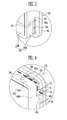
- FIG. 3 illustrates an enlarged view of portion A of FIG. 2 .
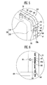
- FIG. 4 illustrates a rotated, enlarged view showing a lower side of FIG. 3 .
- FIG. 5 illustrates a rotated enlarged view schematically showing a state in which a frame portion is provided at the lower side of FIG. 3 .
- FIG. 6 illustrates an enlarged view showing portion B of FIG. 1 .
- the guide portion 150 may be provided in the flange portion 112.
- the guide portion 150 may be provided adjacent to an end portion of the frame portion 120.
- the guide portion 150 may include a groove portion that is inwardly recessed.
- the frame portion 120 may include a pair of first frames 121 configured to face each other at both sides thereof, and a second frame 122 configured to connect the pair of first frames 121.
- the flange portion 112 may include first and second flanges 112a and 112b that respectively contact the first and second frames 121 and 122.
- the guide portion 150 may be provided to extend to the second flange 112b at a lower portion of a bottom of the first flange 112a.
- the guide portion 150 may be provided such that at least one end of the guide portion 150 is sloped.
- the guide portion 150 may be provided to extend from the first flange 112a to the second flange 112b.
- the first flange 112a may include a first end portion 151 and the second flange 112b may include a second end portion 152.
- the guide portion 150 may be provided to extend from the first end portion 151 to the second end portion 152.
- the guide portion 150 may be provided to be recessed inwardly from outer surfaces of the first and second flanges 112a and 112b.
- the section vertical to the first end portion 151 may include a slope portion 151a provided to slope inwardly from the outer surface of the first flange 112a.
- the guide portion 150 may be recessed via the slope portion 151 to gradually have the shape of a diagonal line from the outer surface of the first flange 112a at the beginning of the first end portion 151.
- the base portion 111 contacts the second frame 122.
- the base portion 111 may include a groove portion 140 such that the base portion 111 at the groove portion 140 has a thickness that is thinner than a thickness of a peripheral portion, such that the base portion 111 at the groove portion is spaced apart from a portion of the second frame 122.
- the thickness s2 of the base portion 111 at the groove portion 140 may be formed thinner than the thickness s1 of the peripheral portion of the base portion 111.
- the groove portion 140 may be connected to the guide portion 150.
- the guide portion 150 and the groove portion 140 may be provided to extend to each other so that the second end portion 152 of the guide portion 150 and the end portion of the groove portion 140 are parallel to each other.
- the frame portion 120 may further include a portion provided to be recessed inward from the end thereof.
- the second frame 122 may further include a stepped portion 130 provided at an end portion of the second frame 122 to be recessed lower than a peripheral portion of the second frame.
- the stepped portion 130 may be provided to correspond to the groove portion 140.
- the stepped portion 130 may correspond to the second end portion 152 of the guide portion 150.
- moisture or the like may flow downward at the portion where the side portion 110 and the frame portion 120 are contacted with each other, and then pool in the guide portion 150 provided in the flange portion 112 of the side portion 110.
- the first end portion 151 of the guide portion 151 includes the slope portion 151a, and thus the flow of the moisture may be guided along the slope portion 151 a at the first end portion 151.
- the moisture may flow toward a lower side of the battery pack along the guide portion 150. The moisture may be drained to the outside of the battery pack from the lower side.
- the groove portion 140 may be provided in the base portion 111 to be adjacent to the second end portion 152, and thus the discharge of the moisture can be easily performed.
- the stepped portion 130 provided to the frame portion 120 may expand the discharge path of the moisture, and thus the discharge of the moisture may be more easily performed. Accordingly, the discharge of the moisture may be accelerated by guiding the flow of the moisture that penetrates into the portion where the frame portion 120 and the side portion 110 contact each other, so that it may be possible to increase the lifespan of the battery pack.
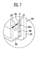
- FIG. 7 illustrates an enlarged view schematically showing a side portion in a battery pack according to another embodiment of the invention.
- the side portion 210 may include a base portion 211 and a flange portion 212.
- the flange portion 212 may be inserted inside a frame portion, to overlap with an inner surface of the frame portion.
- a guide portion 250 capable of guiding the flow of fluid such as moisture may be provided in an outer surface of the flange portion 212.
- a first end portion 251, which is one end of the guide portion 250, may be formed as a diagonal surface having an angle r1 of less than 90 degrees counterclockwise with respect to the base portion 211.
- the flow of moisture that penetrates into a portion where the side portion 210 and the frame portion contact each other may be guided by the guide portion 250 to flow downward.
- the first end portion 251 of the guide portion 250 may be formed as the diagonal surface having the angle r1 of less than 90 degrees, such that the flow of the penetrated moisture may be controlled by the direction of the diagonal surface.
- the flow of the penetrated moisture may be blocked by the diagonal surface of the first end portion 251, and thus the direction of the flow may be controlled such that the moisture does not penetrate into a deep portion inside the frame portion.
- the first end portion 251 of the guide portion 250 may be formed as a diagonal surface having an angle r1 of less than 90 degrees counterclockwise with respect to the base portion 211.
- FIG. 8 illustrates a perspective view of a side portion in a battery pack according to another embodiment.
- FIG. 9 illustrates a sectional view taken along line I-I of FIG. 8 .
- FIG. 10 illustrates a sectional view taken along line II-II of FIG. 8 .
- a side portion 310 and a frame portion 320 may be connected to each other.
- the side portion 310 may include a guide portion 350 provided at a portion where the side portion 310 and the frame portion 320 overlap with each other.
- the side portion 310 may include a base portion 311, and a flange portion 312 that protrudes vertical to the base portion 311, to overlap with an inner surface of the frame portion 320.
- the frame portion 320 may include a pair of first frames provided to face each other, and a second frame 322 provided to extend between the pair of first frames.
- the side portion 310 may further include one or more support portions 313 provided to the outer surface of the second frame 322.
- the flange portion 312 may be connected to the base portion 311, and may be spaced apart from an end 310a of the base portion 311 by a first distance.
- the support portion 313 may protrude outwardly from the end 310a of the base portion 311, to extend parallel to the flange portion 312.
- a space may be provided between the flange portion 312 and the support portion 313, which are provided in parallel to each other.
- the second frame 321 may be inserted between the flange portion 312 and the support portion 313, and thus an end 321a of the second frame 321 may contact the base portion 311.
- the support portion 313 may fix a lower portion of the frame portion 320 and simultaneously may support the weight of the frame portion 320.
- the side portion 310 and the frame portion 320 may be firmly fixed by the support portion 313.
- the support portion 313 may be configured with two support portions 313 provided to be spaced apart from each other, based on the center of the second frame 321.
- the housing may further include a bottom guide portion 360 provided between the two support portions 313 to guide the flow of fluid.
- the bottom guide portion 360 is interposed between the second frame 322 and the support portion 313, to be provided as an empty space.
- the flow of moisture that penetrates between the second frame 321 and the support portion 313 may be easily guided to the bottom guide portion 360. Accordingly, the discharge of the moisture at a lower side in the battery pack can be further accelerated.
- Embodiments provide a battery pack having a housing that has a drainage structure, thereby improving the lifespan of the battery pack and avoiding damage that could be caused by pooled moisture.
Landscapes
- Chemical & Material Sciences (AREA)
- Chemical Kinetics & Catalysis (AREA)
- Electrochemistry (AREA)
- General Chemical & Material Sciences (AREA)
- Engineering & Computer Science (AREA)
- Manufacturing & Machinery (AREA)
- Inorganic Chemistry (AREA)
- Battery Mounting, Suspending (AREA)
Abstract
Description
- The invention relates to a battery pack.
- A high-power battery module using a non-aqueous electrolyte with high energy density has recently been developed. The high-power battery module is configured as a large-capacity battery module manufactured by connecting a plurality of battery cells in series so as to be used in driving motors of devices requiring high power, e.g., electric vehicles and the like.
- A battery pack is formed by accommodating one or more battery modules in a housing. The battery pack may be used as a power source for an external device. In this case, bare cells constituting the battery module may be secondary batteries including a lithium compound, and which can be reversibly charged/discharged.
- The present invention sets out to provide a battery pack that does not differ from the above problems f the prior art.
- As a battery pack is used, condensation water such as water drops may be formed on an outer surface of the battery pack, or cooling water or the like may be sprayed onto the outer surface of the battery pack in order to perform a heat exchange with the battery pack. Moisture may penetrate into a portion of the housing and may not be drained but instead may pool. Such moisture may cause damage to the housing, particularly if it is formed of stainless steel for example. In a serious case, the moisture may cause a short-circuit with the bare cell.
- Embodiments of the invention are directed to a battery pack including a plurality of bare cells electrically connected to one another, and a housing that accommodates the bare cells therein. The housing includes a frame portion and a pair of side portions respectively connected to one end and the other end of the frame portion. The housing includes a guide portion to guide a flow of fluid, the guide portion being located where the one end of the frame portion and one side portion of the pair of side portions are adjacent to each other.
- The guide portion may include a groove portion that is inwardly recessed.
- The frame portion may include a pair of first frames that face each other in a first direction, and a second frame that connects bottoms of the pair of first frames. The side portions may face each other in a second direction perpendicular to the first direction at the one end and the other end of the frame portion.
- A section of the frame portion along the first direction may be in a form of a U shape.
- The one side portion may include a base portion that vertically contacts the one end of the frame portion and a flange portion that protrudes toward the frame portion from the base portion.
- The flange portion may be inwardly spaced from an end of the base portion by a first distance.
- The first distance may correspond to a thickness of the frame portion.
- The flange portion may be insertably coupled to an inside of the frame portion to overlap with the frame portion. The guide portion may be located where the side portion and the frame portion overlap with each other.
- The flange portion may include a first fastening portion. The frame portion may include a second fastening portion fastened to the first fastening portion.
- The guide portion may be located in the flange portion adjacent to the one end of the frame portion.
- The flange portion may include first and second flanges that respectively contact the first frames and the second frame. The guide portion may extend to the second flange at a lower portion of the first flange. At least one end of the guide portion may be sloped.
- A first end portion of the guide portion may be located at the first flange and a second end portion of the guide portion may be located at the second flange. The first end portion of the guide portion and the second end portion of the guide portion may extend to each other. The guide portion may be inwardly recessed from an outer surface of the first flange. A section of the guide portion perpendicular to the first end portion of the guide portion may slope inwardly from the outer surface of the first flange.
- The first end portion may be in a form of a diagonal surface having an angle of less than 90 degrees counterclockwise with respect to the base portion.
- The base portion of the one side portion may further includes a groove portion that contacts the second frame. The base portion where the groove portion is located may have a thickness less than that of a peripheral portion of the base portion such that the base portion where the groove portion is located is spaced apart from the second frame.
- The groove portion may be connected to the guide portion.
- The second frame may further include a stepped portion located at an end portion thereof, the stepped portion of the second frame being stepped inwardly from a peripheral portion of the second frame, the stepped portion of the second frame corresponding to the groove portion of the base portion of the side portion.
- At least one support portion may overlap an outer surface of the second frame at a bottom end of the base portion. The second frame may be inserted between the flange portion and the support portion.
- The support portion may include two support portions that are spaced apart from each other, relative to the center of the second frame. The housing may further include a bottom guide portion between the two support portions.
- The frame portion may be made of stainless steel. The side portions may be made of plastic.
- At least some of the above and other features of the invention are set-out in the claims.
- The guide portion according to embodiments may hence be provided in the battery pack to drain such moisture before damage may occur.
- Features of the invention will be made more apparent to those of skill in the art by describing in detail embodiments thereof with reference to the attached drawings in which:
-
FIG. 1 illustrates a perspective view of a battery pack according to an embodiment of the invention. -
FIG. 2 illustrates an exploded perspective view of the battery pack shown inFIG. 1 . -
FIG. 3 illustrates an enlarged view of portion A ofFIG. 2 . -
FIG. 4 illustrates a rotated, enlarged view showing a lower side ofFIG. 3 . -
FIG. 5 illustrates a rotated, enlarged view schematically showing a state in which a frame portion is provided at the lower side ofFIG. 3 . -
FIG. 6 illustrates an enlarged view showing portion B ofFIG. 1 . -
FIG. 7 illustrates an enlarged view schematically showing a side portion in a battery pack according to another embodiment of the invention. -
FIG. 8 illustrates a rotated, perspective view of a side portion in a battery pack according to still another embodiment of the invention. -
FIG. 9 illustrates a sectional view taken along line I-I ofFIG. 8 . -
FIG. 10 illustrates a sectional view taken along line II-II ofFIG. 8 . - Example embodiments of the invention will now be described more fully hereinafter with reference to the accompanying drawings; however, the invention may be embodied in different forms and should not be construed as limited to the embodiments set forth herein. Rather, these embodiments are provided so that this disclosure will be thorough and complete, and will fully convey suitable implementations to those skilled in the art.
- In the drawing figures, the dimensions of layers and regions may be exaggerated for clarity of illustration. Like reference numerals refer to like elements throughout.
-
FIG. 1 illustrates a perspective view of a battery pack according to an embodiment of the invention.FIG. 2 illustrates an exploded perspective view of the battery pack shown inFIG. 1 . - The
battery pack 100 according to this embodiment may include a plurality ofbare cells 10 electrically coupled to one another, and a housing configured to accommodate thebare cells 10 therein. The housing may include aframe portion 120 and a pair ofside portions 110 respectively connected to oneend 120a and theother end 120b of theframe portion 120. The housing may includes aguide portion 150 formed in an outer surface thereof for guiding the flow of a fluid. Theguide portion 150 may be provided at a portion where theframe portion 120 and one of theside portions 110 are adjacent to each other. Theframe portion 120 may include a pair offirst frames 121 configured to face each other in a first direction, and asecond frame 122 configured to connect bottoms of the pair offirst frames 121. Theside portions 110 may be provided to face each other in a second direction perpendicular to the first direction at the oneend 120a and theother end 120b of theframe portion 120. - After a plurality of
bare cells 10 are aligned, the plurality ofbattery cells 10 may be bundled using a pair ofend plates 18 and a connectingmember 19 for connecting theend plates 18, thereby manufacturing the bundledbattery cells 10 as abattery module 20. Thebare cells 10 may be provided in the form of thebattery module 20 inside the housing. In addition,barriers 50 may be respectively provided between the alignedbare cells 10. Thebarrier 50 may allow adjacentbare cells 10 to be spaced apart from each other, thereby providing the flow path of a fluid such as a heat exchange medium. The heat exchange medium may be heat-exchanged with thebare cells 10 to control the temperature of thebare cells 10. - The
bare cell 10 may be a secondary battery that can be reversibly charged/discharged. Thebare cell 10 may include a battery case, and an electrode assembly and an electrolyte accommodated in the battery case. The battery case may be hermetically sealed with acap assembly 14 having apositive electrode terminal 11, anegative electrode terminal 12 and avent 13. The electrode assembly and the electrolyte may generate electrochemical energy through a reaction therebetween, and the generated energy may be transferred to the outside of thebare cell 10 through the positive andnegative electrode terminals negative electrode terminals bare cells 10 may be electrically connected through a bus-bar 15. The bus-bar 15 may be fixed to the positive andnegative electrode terminals bare cells 10 using a member such as a nut 16. Thevent 13 may serve as a safety device of thebare cell 10, to act as a passage through which gas generated inside thebare cell 10 is exhausted to the outside of thebare cell 10. - The
bare cells 10 manufactured in the form of thebattery module 20 may be accommodated in the housing including theframe portion 120 and theside portions 110. Theframe portion 120 may include the pair offirst frames 121 configured to face each other in the first direction (z-direction), and thesecond frame 122 configured to connect the bottoms of the pair offirst frames 121. For example, the section of theframe portion 120 along the first direction may be formed in a U shape. Theframe portion 120 may be formed approximately in an box shape. In the box shape, an upper portion, and the oneend 120a and theother end 120b of theframe portion 120, may be opened. - The
side portions 110 may be provided to face each other in the second direction vertical to the first direction at the oneend 120a and theother end 120b of theframe portion 120. For example, theside portions 110 may be provided to close the open one end and the other end of theframe portion 120. Through-holes 110a acting as an inlet and an outlet of the heat exchange medium may be provided in theside portions 110, respectively. Thebattery module 20 may be aligned so that a side surface of thebattery module 20 faces the through-hole 110a. With theside portions 110 facing each other, the heat exchange medium may flow into thebattery pack 100 through the through-hole 110a of oneside portion 110 to pass through a space between thebare cells 10 spaced apart from each other by thebarrier 50. Subsequently, the heat exchange medium may flow out to the outside of thebattery pack 100 through the through-hole 110a of theother side portion 110. The heat exchange medium may be heat-exchanged with thebare cells 10 to control the temperature of thebare cells 10. In addition, the heat exchange medium may control the heat generation of thebare cells 10, to improve the safety and reliability of thebare cells 10. - The
side portion 110 may include abase portion 111 that vertically contacts the oneend 120a and theother end 120b of theframe portion 120, and aflange portion 112 that protrudes toward theframe portion 120 from thebase portion 111. Theflange portion 112 may be spaced inwardly from an end of thebase portion 111 by a first distance d. For example, the first distance d may be provided to correspond to the thickness t of theframe portion 120. Theflange portion 112 of theside portion 110 may be inserted inside theframe portion 120 to overlap with theframe portion 120. The oneend 120a and theother end 120b of theframe portion 120 may contact with thebase portion 111. The first distance d and the thickness t of theframe portion 120 may be provided to be similar to each other. Accordingly, theframe portion 120 may be coupled to theside portion 110 without protruding beyond the ends of theside portion 110. - A
first fastening portion 171 may be provided to theflange portion 112, and asecond fastening portion 172 fastened to thefirst fastening portion 171 may be provided to theframe portion 120. The first andsecond fastening portions second fastening portions separate fastening member 30, e.g., a bolt, stud or the like. - The
battery pack 100 according to this embodiment may further include aguide portion 150. Theguide portion 150 may be provided at a portion where theside portion 110 and theframe portion 120 overlap with each other. For example, theguide portion 150 may be provided in an outer surface of theflange portion 112 of theside portion 110. After theflange portion 112 is inserted inside theframe portion 120, theguide portion 150 may be interposed between the outer surface of theflange portion 112 and the inner surface of theframe portion 120. - The
frame portion 120 may be made of stainless steel, and theside portion 110 may be made of plastic. Theframe portion 120 is made of stainless steel, to improve the entire strength of thebattery pack 100. Theside portion 120, having a small area occupied in thebattery pack 100, may be made of plastic. The shape of plastic is easily varied, and thus, the shape of theside portion 110 may be variously implemented. -
FIG. 3 illustrates an enlarged view of portion A ofFIG. 2 .FIG. 4 illustrates a rotated, enlarged view showing a lower side ofFIG. 3 .FIG. 5 illustrates a rotated enlarged view schematically showing a state in which a frame portion is provided at the lower side ofFIG. 3 .FIG. 6 illustrates an enlarged view showing portion B ofFIG. 1 . - Referring to
FIGS. 3 to 5 , theguide portion 150 may be provided in theflange portion 112. Theguide portion 150 may be provided adjacent to an end portion of theframe portion 120. Theguide portion 150 may include a groove portion that is inwardly recessed. - The
frame portion 120 may include a pair offirst frames 121 configured to face each other at both sides thereof, and asecond frame 122 configured to connect the pair offirst frames 121. Theflange portion 112 may include first andsecond flanges second frames guide portion 150 may be provided to extend to thesecond flange 112b at a lower portion of a bottom of thefirst flange 112a. Theguide portion 150 may be provided such that at least one end of theguide portion 150 is sloped. - The
guide portion 150 may be provided to extend from thefirst flange 112a to thesecond flange 112b. Thefirst flange 112a may include afirst end portion 151 and thesecond flange 112b may include asecond end portion 152. Theguide portion 150 may be provided to extend from thefirst end portion 151 to thesecond end portion 152. Theguide portion 150 may be provided to be recessed inwardly from outer surfaces of the first andsecond flanges first end portion 151 may include aslope portion 151a provided to slope inwardly from the outer surface of thefirst flange 112a. Theguide portion 150 may be recessed via theslope portion 151 to gradually have the shape of a diagonal line from the outer surface of thefirst flange 112a at the beginning of thefirst end portion 151. - The
base portion 111 contacts thesecond frame 122. Thebase portion 111 may include agroove portion 140 such that thebase portion 111 at thegroove portion 140 has a thickness that is thinner than a thickness of a peripheral portion, such that thebase portion 111 at the groove portion is spaced apart from a portion of thesecond frame 122. For example, the thickness s2 of thebase portion 111 at thegroove portion 140 may be formed thinner than the thickness s1 of the peripheral portion of thebase portion 111. Thegroove portion 140 may be connected to theguide portion 150. For example, theguide portion 150 and thegroove portion 140 may be provided to extend to each other so that thesecond end portion 152 of theguide portion 150 and the end portion of thegroove portion 140 are parallel to each other. - The
frame portion 120 may further include a portion provided to be recessed inward from the end thereof. For example, thesecond frame 122 may further include a steppedportion 130 provided at an end portion of thesecond frame 122 to be recessed lower than a peripheral portion of the second frame. The steppedportion 130 may be provided to correspond to thegroove portion 140. In addition, the steppedportion 130 may correspond to thesecond end portion 152 of theguide portion 150. - Referring to
FIG. 6 , moisture or the like may flow downward at the portion where theside portion 110 and theframe portion 120 are contacted with each other, and then pool in theguide portion 150 provided in theflange portion 112 of theside portion 110. In this case, thefirst end portion 151 of theguide portion 151 includes theslope portion 151a, and thus the flow of the moisture may be guided along theslope portion 151 a at thefirst end portion 151. In addition, the moisture may flow toward a lower side of the battery pack along theguide portion 150. The moisture may be drained to the outside of the battery pack from the lower side. In this case, thegroove portion 140 may be provided in thebase portion 111 to be adjacent to thesecond end portion 152, and thus the discharge of the moisture can be easily performed. Further, the steppedportion 130 provided to theframe portion 120 may expand the discharge path of the moisture, and thus the discharge of the moisture may be more easily performed. Accordingly, the discharge of the moisture may be accelerated by guiding the flow of the moisture that penetrates into the portion where theframe portion 120 and theside portion 110 contact each other, so that it may be possible to increase the lifespan of the battery pack. - Hereinafter, other embodiments will be described with reference to
FIGS. 7 to 10 . Contents of these embodiments, except the following contents, are similar to those of the embodiment described with reference toFIGS. 1 to 6 , and therefore, a detailed description of similar features will not be repeated. -
FIG. 7 illustrates an enlarged view schematically showing a side portion in a battery pack according to another embodiment of the invention. - Referring to
FIG. 7 , theside portion 210 according to this embodiment may include abase portion 211 and aflange portion 212. Theflange portion 212 may be inserted inside a frame portion, to overlap with an inner surface of the frame portion. In this case, aguide portion 250 capable of guiding the flow of fluid such as moisture may be provided in an outer surface of theflange portion 212. - A
first end portion 251, which is one end of theguide portion 250, may be formed as a diagonal surface having an angle r1 of less than 90 degrees counterclockwise with respect to thebase portion 211. The flow of moisture that penetrates into a portion where theside portion 210 and the frame portion contact each other may be guided by theguide portion 250 to flow downward. In this case, thefirst end portion 251 of theguide portion 250 may be formed as the diagonal surface having the angle r1 of less than 90 degrees, such that the flow of the penetrated moisture may be controlled by the direction of the diagonal surface. For example, the flow of the penetrated moisture may be blocked by the diagonal surface of thefirst end portion 251, and thus the direction of the flow may be controlled such that the moisture does not penetrate into a deep portion inside the frame portion. On the other hand, if thefirst end portion 251 were to be formed as a diagonal surface 251' having an angle r2 of over 90 degrees, the flow of the penetrated moisture may be guided along the diagonal surface 251' having the angle r2 of over 90 degrees in the direction of the arrow shown inFIG. 7 . Therefore, the penetrated moisture may not be discharged but may flow inside the frame portion. Accordingly, in the battery pack according to this embodiment, thefirst end portion 251 of theguide portion 250 may be formed as a diagonal surface having an angle r1 of less than 90 degrees counterclockwise with respect to thebase portion 211. -
FIG. 8 illustrates a perspective view of a side portion in a battery pack according to another embodiment.FIG. 9 illustrates a sectional view taken along line I-I ofFIG. 8 .FIG. 10 illustrates a sectional view taken along line II-II ofFIG. 8 . - Referring to
FIGS. 8 to 10 , in the battery pack according to this embodiment, aside portion 310 and aframe portion 320 may be connected to each other. Theside portion 310 may include aguide portion 350 provided at a portion where theside portion 310 and theframe portion 320 overlap with each other. Theside portion 310 may include abase portion 311, and aflange portion 312 that protrudes vertical to thebase portion 311, to overlap with an inner surface of theframe portion 320. Theframe portion 320 may include a pair of first frames provided to face each other, and a second frame 322 provided to extend between the pair of first frames. - The
side portion 310 may further include one ormore support portions 313 provided to the outer surface of the second frame 322. In this case, theflange portion 312 may be connected to thebase portion 311, and may be spaced apart from anend 310a of thebase portion 311 by a first distance. Thesupport portion 313 may protrude outwardly from theend 310a of thebase portion 311, to extend parallel to theflange portion 312. - Referring to
FIG. 9 , a space may be provided between theflange portion 312 and thesupport portion 313, which are provided in parallel to each other. Thesecond frame 321 may be inserted between theflange portion 312 and thesupport portion 313, and thus anend 321a of thesecond frame 321 may contact thebase portion 311. Thesupport portion 313 may fix a lower portion of theframe portion 320 and simultaneously may support the weight of theframe portion 320. Thus, theside portion 310 and theframe portion 320 may be firmly fixed by thesupport portion 313. - Referring to
FIG. 10 , thesupport portion 313 may be configured with twosupport portions 313 provided to be spaced apart from each other, based on the center of thesecond frame 321. The housing may further include abottom guide portion 360 provided between the twosupport portions 313 to guide the flow of fluid. Thebottom guide portion 360 is interposed between the second frame 322 and thesupport portion 313, to be provided as an empty space. The flow of moisture that penetrates between thesecond frame 321 and thesupport portion 313 may be easily guided to thebottom guide portion 360. Accordingly, the discharge of the moisture at a lower side in the battery pack can be further accelerated. - By way of summation and review, a lightweight battery pack generating high power and having improved electrochemical stability is desirable. Embodiments provide a battery pack having a housing that has a drainage structure, thereby improving the lifespan of the battery pack and avoiding damage that could be caused by pooled moisture.
- Example embodiments have been disclosed herein, and although specific terms are employed, they are used and are to be interpreted in a generic and descriptive sense only and not for purpose of limitation. In some instances, as would be apparent to one of ordinary skill in the art as of the filing of the present application, features, characteristics, and/or elements described in connection with a particular embodiment may be used singly or in combination with features, characteristics, and/or elements described in connection with other embodiments unless otherwise specifically indicated. Accordingly, it will be understood by those of skill in the art that various changes in form and details may be made without departing from the scope thereof as set forth in the following claims.
Claims (19)
- A battery pack, comprising:a plurality of bare cells electrically connected to one another; anda housing that accommodates the bare cells therein, the housing including a frame portion and a pair of side portions respectively connected to a first end and a second end of the frame portion,wherein the housing includes a guide portion to guide a flow of fluid, the guide portion being located where the first end of the frame portion and one said side portion are adjacent to each other.
- A battery pack as claimed in claim 1, wherein the guide portion includes a groove portion that is inwardly recessed.
- A battery pack as claimed in claim 1 or 2, wherein:the frame portion includes a pair of first frames that face each other in a first direction, and a second frame that connects bottoms of the pair of first frames, andthe side portions face each other in a second direction perpendicular to the first direction at the first end and the second end of the frame portion.
- A battery pack as claimed in claim 3, wherein a section of the frame portion along the first direction is in a form of a U shape.
- A battery pack as claimed in claim 3 or 4, wherein the one said side portion includes a base portion that vertically contacts the first end of the frame portion, and a flange portion that protrudes toward the frame portion from the base portion.
- A battery pack as claimed in claim 5, wherein the flange portion is inwardly spaced from an end of the base portion by a first distance.
- A battery pack as claimed in claim 6, wherein the first distance corresponds to a thickness of the frame portion.
- A battery pack as claimed in claim 5, 6 or 7, wherein:the flange portion is insertably coupled to an inside of the frame portion to overlap with the frame portion, andthe guide portion is located where the side portion and the frame portion overlap with each other.
- A battery pack as claimed in claim 5, 6, 7 or 8, wherein:the flange portion includes a first fastening portion, andthe frame portion includes a second fastening portion fastened to the first fastening portion.
- A battery pack as claimed in one of claims 5 to 9, wherein the guide portion is located in the flange portion adjacent to the first end of the frame portion.
- A battery pack as claimed in one of claims 5 to 10, wherein:the flange portion includes first and second flanges that respectively contact the first frames and the second frame,the guide portion extends to the second flange at a lower portion of the first flange, andat least one end of the guide portion is sloped.
- A battery pack as claimed in claim 11, wherein:a first end portion of the guide portion is located at the first flange and a second end portion of the guide portion is located at the second flange, the first end portion of the guide portion and the second end portion of the guide portion extending to each other,the guide portion is inwardly recessed from an outer surface of the first flange,
anda section of the guide portion perpendicular to the first end portion of the guide portion slopes inwardly from the outer surface of the first flange. - A battery pack as claimed in claim 12, wherein the first end portion is in a form of a diagonal surface having an angle of less than 90 degrees counterclockwise with respect to the base portion.
- A battery pack as claimed in one of claims 5 to 13, wherein the base portion of the one side portion further includes a groove portion that contacts the second frame, the base portion where the groove portion is located having a thickness less than that of a peripheral portion of the base portion such that the base portion where the groove portion is located is spaced apart from the second frame.
- A battery pack as claimed in claim 14, wherein the groove portion is connected to the guide portion.
- A battery pack as claimed in claim 14 or 15, wherein the second frame further includes a stepped portion located at an end portion thereof, the stepped portion of the second frame being stepped inwardly from a peripheral portion of the second frame, the stepped portion of the second frame corresponding to the groove portion of the base portion of the side portion.
- A battery pack as claimed in one of claims 5 to 16, wherein:at least one support portion overlaps an outer surface of the second frame at a bottom end of the base portion, andthe second frame is inserted between the flange portion and the support portion.
- A battery pack as claimed in claim 17, wherein:the support portion includes two support portions that are spaced apart from each other, relative to the center of the second frame, andthe housing further includes a bottom guide portion between the two support portions.
- A battery pack as claimed in any preceding claim, wherein:the frame portion is made of stainless steel, andthe side portions are made of plastic.
Applications Claiming Priority (1)
| Application Number | Priority Date | Filing Date | Title |
|---|---|---|---|
| KR1020130103149A KR101688486B1 (en) | 2013-08-29 | 2013-08-29 | Battery pack |
Publications (2)
| Publication Number | Publication Date |
|---|---|
| EP2843724A1 true EP2843724A1 (en) | 2015-03-04 |
| EP2843724B1 EP2843724B1 (en) | 2016-11-09 |
Family
ID=51454569
Family Applications (1)
| Application Number | Title | Priority Date | Filing Date |
|---|---|---|---|
| EP14182928.3A Active EP2843724B1 (en) | 2013-08-29 | 2014-08-29 | A housing for battery pack with a drainage structure |
Country Status (3)
| Country | Link |
|---|---|
| US (1) | US9590280B2 (en) |
| EP (1) | EP2843724B1 (en) |
| KR (1) | KR101688486B1 (en) |
Families Citing this family (10)
| Publication number | Priority date | Publication date | Assignee | Title |
|---|---|---|---|---|
| KR102331723B1 (en) | 2017-03-21 | 2021-11-26 | 삼성에스디아이 주식회사 | colling apparatus for battery pack |
| KR102065105B1 (en) | 2017-04-14 | 2020-01-10 | 주식회사 엘지화학 | Drawer type battery pack |
| KR102106376B1 (en) * | 2018-07-11 | 2020-05-04 | 한국해양과학기술원 | Marine organism antifouling device for seawater battery |
| KR102759358B1 (en) * | 2019-09-27 | 2025-01-22 | 주식회사 엘지에너지솔루션 | Battery module, method of manufacturing the same and battery pack |
| KR102398574B1 (en) * | 2019-10-10 | 2022-05-13 | 주식회사 엘지에너지솔루션 | Battery module and battery pack including the same |
| US11799150B2 (en) | 2020-07-17 | 2023-10-24 | Toyota Motor Engineering & Manufacturing North America, Inc. | Cooling structure for hybrid-electric vehicle battery cell assemblies |
| DE102021205960A1 (en) | 2021-06-11 | 2022-12-15 | Robert Bosch Gesellschaft mit beschränkter Haftung | Housing arrangement for a battery module, electronics housing, battery housing and battery module |
| DE102021207363A1 (en) | 2021-07-12 | 2023-01-12 | Robert Bosch Gesellschaft mit beschränkter Haftung | Housing arrangement for a battery module, electronics housing, battery housing and battery module |
| CN114421073B (en) * | 2021-12-21 | 2024-05-31 | 安徽鑫铂铝业股份有限公司 | Aluminum alloy section bar for power equipment convenient to dismouting |
| USD1095406S1 (en) * | 2023-04-19 | 2025-09-30 | Sungrow Power Supply Co., Ltd. | Battery pack |
Citations (11)
| Publication number | Priority date | Publication date | Assignee | Title |
|---|---|---|---|---|
| WO2005043650A2 (en) * | 2003-10-28 | 2005-05-12 | Johnson Controls Technology Company | Battery system with improved heat dissipation |
| US20080057392A1 (en) * | 2006-08-31 | 2008-03-06 | Nissan Motor Co., Ltd. | Battery module |
| CN101584059A (en) * | 2007-09-28 | 2009-11-18 | 三菱自动车工业株式会社 | Battery unit |
| US20100073005A1 (en) * | 2008-09-24 | 2010-03-25 | Jyunya Yano | Car battery system |
| US20110111282A1 (en) * | 2009-11-12 | 2011-05-12 | Koichi Nagamine | Power storage apparatus |
| US20110212355A1 (en) * | 2010-02-26 | 2011-09-01 | Gm Global Technology Operations, Inc. | U-formed cooling plate with solid fins for lithium pouch cells |
| US20120224326A1 (en) * | 2009-09-07 | 2012-09-06 | Markus Kohlberger | Modular battery structure |
| WO2012133709A1 (en) * | 2011-03-31 | 2012-10-04 | 三洋電機株式会社 | Power source device, and vehicle provided with power source device |
| DE102011082562A1 (en) * | 2011-09-13 | 2013-03-14 | Sb Limotive Company Ltd. | Battery module e.g. lithium ion battery module for motor vehicle, has two coolant chambers that are provided in module housing in which coolant inlet and coolant outlet are provided |
| EP2597700A1 (en) * | 2011-11-22 | 2013-05-29 | Samsung SDI Co., Ltd. | Battery pack |
| WO2013077176A1 (en) * | 2011-11-25 | 2013-05-30 | 三洋電機株式会社 | Battery pack |
Family Cites Families (5)
| Publication number | Priority date | Publication date | Assignee | Title |
|---|---|---|---|---|
| KR19980021898U (en) | 1996-10-24 | 1998-07-15 | 김영귀 | Battery compartment for drive battery for electric vehicle |
| KR20000015883U (en) | 1999-01-19 | 2000-08-16 | 정몽규 | Battery tray for automobile |
| TW200835028A (en) * | 2007-02-15 | 2008-08-16 | Simplo Technology Co Ltd | Closed packing process of extra thin battery and product thereof |
| KR101209684B1 (en) | 2010-11-17 | 2012-12-10 | 기아자동차주식회사 | Stack manifold insert having guide for distributing the flow of fluid and fuel cell stack comprising the same |
| JP6083170B2 (en) * | 2011-10-26 | 2017-02-22 | 株式会社Gsユアサ | Electricity storage element |
-
2013
- 2013-08-29 KR KR1020130103149A patent/KR101688486B1/en active Active
-
2014
- 2014-08-25 US US14/467,124 patent/US9590280B2/en active Active
- 2014-08-29 EP EP14182928.3A patent/EP2843724B1/en active Active
Patent Citations (11)
| Publication number | Priority date | Publication date | Assignee | Title |
|---|---|---|---|---|
| WO2005043650A2 (en) * | 2003-10-28 | 2005-05-12 | Johnson Controls Technology Company | Battery system with improved heat dissipation |
| US20080057392A1 (en) * | 2006-08-31 | 2008-03-06 | Nissan Motor Co., Ltd. | Battery module |
| CN101584059A (en) * | 2007-09-28 | 2009-11-18 | 三菱自动车工业株式会社 | Battery unit |
| US20100073005A1 (en) * | 2008-09-24 | 2010-03-25 | Jyunya Yano | Car battery system |
| US20120224326A1 (en) * | 2009-09-07 | 2012-09-06 | Markus Kohlberger | Modular battery structure |
| US20110111282A1 (en) * | 2009-11-12 | 2011-05-12 | Koichi Nagamine | Power storage apparatus |
| US20110212355A1 (en) * | 2010-02-26 | 2011-09-01 | Gm Global Technology Operations, Inc. | U-formed cooling plate with solid fins for lithium pouch cells |
| WO2012133709A1 (en) * | 2011-03-31 | 2012-10-04 | 三洋電機株式会社 | Power source device, and vehicle provided with power source device |
| DE102011082562A1 (en) * | 2011-09-13 | 2013-03-14 | Sb Limotive Company Ltd. | Battery module e.g. lithium ion battery module for motor vehicle, has two coolant chambers that are provided in module housing in which coolant inlet and coolant outlet are provided |
| EP2597700A1 (en) * | 2011-11-22 | 2013-05-29 | Samsung SDI Co., Ltd. | Battery pack |
| WO2013077176A1 (en) * | 2011-11-25 | 2013-05-30 | 三洋電機株式会社 | Battery pack |
Also Published As
| Publication number | Publication date |
|---|---|
| KR20150025560A (en) | 2015-03-11 |
| KR101688486B1 (en) | 2016-12-21 |
| US20150064522A1 (en) | 2015-03-05 |
| US9590280B2 (en) | 2017-03-07 |
| EP2843724B1 (en) | 2016-11-09 |
Similar Documents
| Publication | Publication Date | Title |
|---|---|---|
| US9590280B2 (en) | Battery pack | |
| US8932749B2 (en) | Battery module | |
| US9548475B2 (en) | Battery cell of irregular structure and battery module employed with the same | |
| EP3151307B1 (en) | Battery module and battery pack comprising same | |
| KR101223568B1 (en) | Rechargeable battery and battery module | |
| US9166260B2 (en) | Battery module | |
| US8795881B2 (en) | Terminal of rechargeable battery, method of assembling the terminal of rechargeable battery, rechargeable battery module and method of assembling the rechargeable battery module | |
| US8734979B2 (en) | Battery module | |
| US9991485B2 (en) | Battery module having venting guiding portion | |
| EP2654101B1 (en) | Battery pack | |
| US20140295235A1 (en) | Battery module | |
| EP2988344A1 (en) | Battery module having novel structure and battery pack comprising same | |
| US9484607B2 (en) | Battery module | |
| KR20130116087A (en) | Rechargeable battery and module thereof | |
| KR102113155B1 (en) | Battery module and battery pack | |
| US20180040863A1 (en) | Battery pack and manufacturing method therefor | |
| KR20130058588A (en) | Rechargeable battery | |
| US9356326B2 (en) | Top cover and battery pack having the same | |
| US9153809B2 (en) | Secondary battery including retainer for electrode assembly | |
| KR20170086346A (en) | Battery cell | |
| US9553287B2 (en) | Battery pack | |
| KR101658587B1 (en) | Lithium Secondary Battery and Battery Pack Comprising The Same | |
| JP2016225031A (en) | Secondary battery module | |
| KR20120066877A (en) | Rechargeable battery | |
| KR102576583B1 (en) | Bettery cell |
Legal Events
| Date | Code | Title | Description |
|---|---|---|---|
| 17P | Request for examination filed |
Effective date: 20140829 |
|
| AK | Designated contracting states |
Kind code of ref document: A1 Designated state(s): AL AT BE BG CH CY CZ DE DK EE ES FI FR GB GR HR HU IE IS IT LI LT LU LV MC MK MT NL NO PL PT RO RS SE SI SK SM TR |
|
| AX | Request for extension of the european patent |
Extension state: BA ME |
|
| PUAI | Public reference made under article 153(3) epc to a published international application that has entered the european phase |
Free format text: ORIGINAL CODE: 0009012 |
|
| R17P | Request for examination filed (corrected) |
Effective date: 20150904 |
|
| RBV | Designated contracting states (corrected) |
Designated state(s): AL AT BE BG CH CY CZ DE DK EE ES FI FR GB GR HR HU IE IS IT LI LT LU LV MC MK MT NL NO PL PT RO RS SE SI SK SM TR |
|
| REG | Reference to a national code |
Ref country code: DE Ref legal event code: R079 Ref document number: 602014004703 Country of ref document: DE Free format text: PREVIOUS MAIN CLASS: H01M0002000000 Ipc: H01M0010625000 |
|
| GRAP | Despatch of communication of intention to grant a patent |
Free format text: ORIGINAL CODE: EPIDOSNIGR1 |
|
| RIC1 | Information provided on ipc code assigned before grant |
Ipc: H01M 10/613 20140101ALI20160428BHEP Ipc: H01M 2/10 20060101ALI20160428BHEP Ipc: H01M 10/625 20140101AFI20160428BHEP Ipc: H01M 10/6556 20140101ALI20160428BHEP |
|
| INTG | Intention to grant announced |
Effective date: 20160524 |
|
| GRAS | Grant fee paid |
Free format text: ORIGINAL CODE: EPIDOSNIGR3 |
|
| GRAA | (expected) grant |
Free format text: ORIGINAL CODE: 0009210 |
|
| AK | Designated contracting states |
Kind code of ref document: B1 Designated state(s): AL AT BE BG CH CY CZ DE DK EE ES FI FR GB GR HR HU IE IS IT LI LT LU LV MC MK MT NL NO PL PT RO RS SE SI SK SM TR |
|
| REG | Reference to a national code |
Ref country code: GB Ref legal event code: FG4D |
|
| REG | Reference to a national code |
Ref country code: AT Ref legal event code: REF Ref document number: 844666 Country of ref document: AT Kind code of ref document: T Effective date: 20161115 Ref country code: CH Ref legal event code: EP |
|
| REG | Reference to a national code |
Ref country code: IE Ref legal event code: FG4D |
|
| REG | Reference to a national code |
Ref country code: DE Ref legal event code: R096 Ref document number: 602014004703 Country of ref document: DE |
|
| PG25 | Lapsed in a contracting state [announced via postgrant information from national office to epo] |
Ref country code: LV Free format text: LAPSE BECAUSE OF FAILURE TO SUBMIT A TRANSLATION OF THE DESCRIPTION OR TO PAY THE FEE WITHIN THE PRESCRIBED TIME-LIMIT Effective date: 20161109 |
|
| REG | Reference to a national code |
Ref country code: LT Ref legal event code: MG4D |
|
| REG | Reference to a national code |
Ref country code: NL Ref legal event code: MP Effective date: 20161109 |
|
| REG | Reference to a national code |
Ref country code: AT Ref legal event code: MK05 Ref document number: 844666 Country of ref document: AT Kind code of ref document: T Effective date: 20161109 |
|
| PG25 | Lapsed in a contracting state [announced via postgrant information from national office to epo] |
Ref country code: NL Free format text: LAPSE BECAUSE OF FAILURE TO SUBMIT A TRANSLATION OF THE DESCRIPTION OR TO PAY THE FEE WITHIN THE PRESCRIBED TIME-LIMIT Effective date: 20161109 Ref country code: GR Free format text: LAPSE BECAUSE OF FAILURE TO SUBMIT A TRANSLATION OF THE DESCRIPTION OR TO PAY THE FEE WITHIN THE PRESCRIBED TIME-LIMIT Effective date: 20170210 Ref country code: LT Free format text: LAPSE BECAUSE OF FAILURE TO SUBMIT A TRANSLATION OF THE DESCRIPTION OR TO PAY THE FEE WITHIN THE PRESCRIBED TIME-LIMIT Effective date: 20161109 Ref country code: SE Free format text: LAPSE BECAUSE OF FAILURE TO SUBMIT A TRANSLATION OF THE DESCRIPTION OR TO PAY THE FEE WITHIN THE PRESCRIBED TIME-LIMIT Effective date: 20161109 Ref country code: NO Free format text: LAPSE BECAUSE OF FAILURE TO SUBMIT A TRANSLATION OF THE DESCRIPTION OR TO PAY THE FEE WITHIN THE PRESCRIBED TIME-LIMIT Effective date: 20170209 |
|
| PG25 | Lapsed in a contracting state [announced via postgrant information from national office to epo] |
Ref country code: FI Free format text: LAPSE BECAUSE OF FAILURE TO SUBMIT A TRANSLATION OF THE DESCRIPTION OR TO PAY THE FEE WITHIN THE PRESCRIBED TIME-LIMIT Effective date: 20161109 Ref country code: HR Free format text: LAPSE BECAUSE OF FAILURE TO SUBMIT A TRANSLATION OF THE DESCRIPTION OR TO PAY THE FEE WITHIN THE PRESCRIBED TIME-LIMIT Effective date: 20161109 Ref country code: IS Free format text: LAPSE BECAUSE OF FAILURE TO SUBMIT A TRANSLATION OF THE DESCRIPTION OR TO PAY THE FEE WITHIN THE PRESCRIBED TIME-LIMIT Effective date: 20170309 Ref country code: PL Free format text: LAPSE BECAUSE OF FAILURE TO SUBMIT A TRANSLATION OF THE DESCRIPTION OR TO PAY THE FEE WITHIN THE PRESCRIBED TIME-LIMIT Effective date: 20161109 Ref country code: AT Free format text: LAPSE BECAUSE OF FAILURE TO SUBMIT A TRANSLATION OF THE DESCRIPTION OR TO PAY THE FEE WITHIN THE PRESCRIBED TIME-LIMIT Effective date: 20161109 Ref country code: ES Free format text: LAPSE BECAUSE OF FAILURE TO SUBMIT A TRANSLATION OF THE DESCRIPTION OR TO PAY THE FEE WITHIN THE PRESCRIBED TIME-LIMIT Effective date: 20161109 Ref country code: RS Free format text: LAPSE BECAUSE OF FAILURE TO SUBMIT A TRANSLATION OF THE DESCRIPTION OR TO PAY THE FEE WITHIN THE PRESCRIBED TIME-LIMIT Effective date: 20161109 Ref country code: PT Free format text: LAPSE BECAUSE OF FAILURE TO SUBMIT A TRANSLATION OF THE DESCRIPTION OR TO PAY THE FEE WITHIN THE PRESCRIBED TIME-LIMIT Effective date: 20170309 |
|
| REG | Reference to a national code |
Ref country code: FR Ref legal event code: PLFP Year of fee payment: 4 |
|
| PG25 | Lapsed in a contracting state [announced via postgrant information from national office to epo] |
Ref country code: EE Free format text: LAPSE BECAUSE OF FAILURE TO SUBMIT A TRANSLATION OF THE DESCRIPTION OR TO PAY THE FEE WITHIN THE PRESCRIBED TIME-LIMIT Effective date: 20161109 Ref country code: SK Free format text: LAPSE BECAUSE OF FAILURE TO SUBMIT A TRANSLATION OF THE DESCRIPTION OR TO PAY THE FEE WITHIN THE PRESCRIBED TIME-LIMIT Effective date: 20161109 Ref country code: CZ Free format text: LAPSE BECAUSE OF FAILURE TO SUBMIT A TRANSLATION OF THE DESCRIPTION OR TO PAY THE FEE WITHIN THE PRESCRIBED TIME-LIMIT Effective date: 20161109 Ref country code: DK Free format text: LAPSE BECAUSE OF FAILURE TO SUBMIT A TRANSLATION OF THE DESCRIPTION OR TO PAY THE FEE WITHIN THE PRESCRIBED TIME-LIMIT Effective date: 20161109 Ref country code: RO Free format text: LAPSE BECAUSE OF FAILURE TO SUBMIT A TRANSLATION OF THE DESCRIPTION OR TO PAY THE FEE WITHIN THE PRESCRIBED TIME-LIMIT Effective date: 20161109 |
|
| REG | Reference to a national code |
Ref country code: DE Ref legal event code: R097 Ref document number: 602014004703 Country of ref document: DE |
|
| PG25 | Lapsed in a contracting state [announced via postgrant information from national office to epo] |
Ref country code: BE Free format text: LAPSE BECAUSE OF FAILURE TO SUBMIT A TRANSLATION OF THE DESCRIPTION OR TO PAY THE FEE WITHIN THE PRESCRIBED TIME-LIMIT Effective date: 20161109 Ref country code: SM Free format text: LAPSE BECAUSE OF FAILURE TO SUBMIT A TRANSLATION OF THE DESCRIPTION OR TO PAY THE FEE WITHIN THE PRESCRIBED TIME-LIMIT Effective date: 20161109 Ref country code: IT Free format text: LAPSE BECAUSE OF FAILURE TO SUBMIT A TRANSLATION OF THE DESCRIPTION OR TO PAY THE FEE WITHIN THE PRESCRIBED TIME-LIMIT Effective date: 20161109 Ref country code: BG Free format text: LAPSE BECAUSE OF FAILURE TO SUBMIT A TRANSLATION OF THE DESCRIPTION OR TO PAY THE FEE WITHIN THE PRESCRIBED TIME-LIMIT Effective date: 20170209 |
|
| PLBE | No opposition filed within time limit |
Free format text: ORIGINAL CODE: 0009261 |
|
| STAA | Information on the status of an ep patent application or granted ep patent |
Free format text: STATUS: NO OPPOSITION FILED WITHIN TIME LIMIT |
|
| 26N | No opposition filed |
Effective date: 20170810 |
|
| PG25 | Lapsed in a contracting state [announced via postgrant information from national office to epo] |
Ref country code: SI Free format text: LAPSE BECAUSE OF FAILURE TO SUBMIT A TRANSLATION OF THE DESCRIPTION OR TO PAY THE FEE WITHIN THE PRESCRIBED TIME-LIMIT Effective date: 20161109 |
|
| REG | Reference to a national code |
Ref country code: CH Ref legal event code: PL |
|
| PG25 | Lapsed in a contracting state [announced via postgrant information from national office to epo] |
Ref country code: MC Free format text: LAPSE BECAUSE OF FAILURE TO SUBMIT A TRANSLATION OF THE DESCRIPTION OR TO PAY THE FEE WITHIN THE PRESCRIBED TIME-LIMIT Effective date: 20161109 |
|
| PG25 | Lapsed in a contracting state [announced via postgrant information from national office to epo] |
Ref country code: CH Free format text: LAPSE BECAUSE OF NON-PAYMENT OF DUE FEES Effective date: 20170831 Ref country code: LI Free format text: LAPSE BECAUSE OF NON-PAYMENT OF DUE FEES Effective date: 20170831 |
|
| REG | Reference to a national code |
Ref country code: IE Ref legal event code: MM4A |
|
| PG25 | Lapsed in a contracting state [announced via postgrant information from national office to epo] |
Ref country code: LU Free format text: LAPSE BECAUSE OF NON-PAYMENT OF DUE FEES Effective date: 20170829 |
|
| REG | Reference to a national code |
Ref country code: FR Ref legal event code: PLFP Year of fee payment: 5 |
|
| PG25 | Lapsed in a contracting state [announced via postgrant information from national office to epo] |
Ref country code: IE Free format text: LAPSE BECAUSE OF NON-PAYMENT OF DUE FEES Effective date: 20170829 |
|
| PG25 | Lapsed in a contracting state [announced via postgrant information from national office to epo] |
Ref country code: MT Free format text: LAPSE BECAUSE OF NON-PAYMENT OF DUE FEES Effective date: 20170829 |
|
| PG25 | Lapsed in a contracting state [announced via postgrant information from national office to epo] |
Ref country code: HU Free format text: LAPSE BECAUSE OF FAILURE TO SUBMIT A TRANSLATION OF THE DESCRIPTION OR TO PAY THE FEE WITHIN THE PRESCRIBED TIME-LIMIT; INVALID AB INITIO Effective date: 20140829 |
|
| PG25 | Lapsed in a contracting state [announced via postgrant information from national office to epo] |
Ref country code: CY Free format text: LAPSE BECAUSE OF FAILURE TO SUBMIT A TRANSLATION OF THE DESCRIPTION OR TO PAY THE FEE WITHIN THE PRESCRIBED TIME-LIMIT Effective date: 20161109 |
|
| PG25 | Lapsed in a contracting state [announced via postgrant information from national office to epo] |
Ref country code: MK Free format text: LAPSE BECAUSE OF FAILURE TO SUBMIT A TRANSLATION OF THE DESCRIPTION OR TO PAY THE FEE WITHIN THE PRESCRIBED TIME-LIMIT Effective date: 20161109 |
|
| PG25 | Lapsed in a contracting state [announced via postgrant information from national office to epo] |
Ref country code: TR Free format text: LAPSE BECAUSE OF FAILURE TO SUBMIT A TRANSLATION OF THE DESCRIPTION OR TO PAY THE FEE WITHIN THE PRESCRIBED TIME-LIMIT Effective date: 20161109 |
|
| PG25 | Lapsed in a contracting state [announced via postgrant information from national office to epo] |
Ref country code: AL Free format text: LAPSE BECAUSE OF FAILURE TO SUBMIT A TRANSLATION OF THE DESCRIPTION OR TO PAY THE FEE WITHIN THE PRESCRIBED TIME-LIMIT Effective date: 20161109 |
|
| P01 | Opt-out of the competence of the unified patent court (upc) registered |
Effective date: 20230528 |
|
| PGFP | Annual fee paid to national office [announced via postgrant information from national office to epo] |
Ref country code: DE Payment date: 20250805 Year of fee payment: 12 |
|
| PGFP | Annual fee paid to national office [announced via postgrant information from national office to epo] |
Ref country code: GB Payment date: 20250731 Year of fee payment: 12 |
|
| PGFP | Annual fee paid to national office [announced via postgrant information from national office to epo] |
Ref country code: FR Payment date: 20250808 Year of fee payment: 12 |