EP2843443A1 - Pet-mri device - Google Patents
Pet-mri device Download PDFInfo
- Publication number
- EP2843443A1 EP2843443A1 EP13781234.3A EP13781234A EP2843443A1 EP 2843443 A1 EP2843443 A1 EP 2843443A1 EP 13781234 A EP13781234 A EP 13781234A EP 2843443 A1 EP2843443 A1 EP 2843443A1
- Authority
- EP
- European Patent Office
- Prior art keywords
- pet detector
- pet
- bore
- moving mechanism
- detector
- Prior art date
- Legal status (The legal status is an assumption and is not a legal conclusion. Google has not performed a legal analysis and makes no representation as to the accuracy of the status listed.)
- Granted
Links
Images






Classifications
-
- G—PHYSICS
- G01—MEASURING; TESTING
- G01R—MEASURING ELECTRIC VARIABLES; MEASURING MAGNETIC VARIABLES
- G01R33/00—Arrangements or instruments for measuring magnetic variables
- G01R33/20—Arrangements or instruments for measuring magnetic variables involving magnetic resonance
- G01R33/44—Arrangements or instruments for measuring magnetic variables involving magnetic resonance using nuclear magnetic resonance [NMR]
- G01R33/48—NMR imaging systems
- G01R33/4808—Multimodal MR, e.g. MR combined with positron emission tomography [PET], MR combined with ultrasound or MR combined with computed tomography [CT]
- G01R33/481—MR combined with positron emission tomography [PET] or single photon emission computed tomography [SPECT]
-
- A—HUMAN NECESSITIES
- A61—MEDICAL OR VETERINARY SCIENCE; HYGIENE
- A61B—DIAGNOSIS; SURGERY; IDENTIFICATION
- A61B5/00—Measuring for diagnostic purposes; Identification of persons
- A61B5/0033—Features or image-related aspects of imaging apparatus, e.g. for MRI, optical tomography or impedance tomography apparatus; Arrangements of imaging apparatus in a room
- A61B5/0035—Features or image-related aspects of imaging apparatus, e.g. for MRI, optical tomography or impedance tomography apparatus; Arrangements of imaging apparatus in a room adapted for acquisition of images from more than one imaging mode, e.g. combining MRI and optical tomography
-
- A—HUMAN NECESSITIES
- A61—MEDICAL OR VETERINARY SCIENCE; HYGIENE
- A61B—DIAGNOSIS; SURGERY; IDENTIFICATION
- A61B5/00—Measuring for diagnostic purposes; Identification of persons
- A61B5/05—Detecting, measuring or recording for diagnosis by means of electric currents or magnetic fields; Measuring using microwaves or radio waves
- A61B5/055—Detecting, measuring or recording for diagnosis by means of electric currents or magnetic fields; Measuring using microwaves or radio waves involving electronic [EMR] or nuclear [NMR] magnetic resonance, e.g. magnetic resonance imaging
-
- A—HUMAN NECESSITIES
- A61—MEDICAL OR VETERINARY SCIENCE; HYGIENE
- A61B—DIAGNOSIS; SURGERY; IDENTIFICATION
- A61B5/00—Measuring for diagnostic purposes; Identification of persons
- A61B5/70—Means for positioning the patient in relation to the detecting, measuring or recording means
- A61B5/704—Tables
-
- A—HUMAN NECESSITIES
- A61—MEDICAL OR VETERINARY SCIENCE; HYGIENE
- A61B—DIAGNOSIS; SURGERY; IDENTIFICATION
- A61B6/00—Apparatus or devices for radiation diagnosis; Apparatus or devices for radiation diagnosis combined with radiation therapy equipment
- A61B6/02—Arrangements for diagnosis sequentially in different planes; Stereoscopic radiation diagnosis
- A61B6/03—Computed tomography [CT]
- A61B6/037—Emission tomography
-
- G—PHYSICS
- G01—MEASURING; TESTING
- G01R—MEASURING ELECTRIC VARIABLES; MEASURING MAGNETIC VARIABLES
- G01R33/00—Arrangements or instruments for measuring magnetic variables
- G01R33/20—Arrangements or instruments for measuring magnetic variables involving magnetic resonance
- G01R33/28—Details of apparatus provided for in groups G01R33/44 - G01R33/64
- G01R33/30—Sample handling arrangements, e.g. sample cells, spinning mechanisms
- G01R33/307—Sample handling arrangements, e.g. sample cells, spinning mechanisms specially adapted for moving the sample relative to the MR system, e.g. spinning mechanisms, flow cells or means for positioning the sample inside a spectrometer
-
- G—PHYSICS
- G01—MEASURING; TESTING
- G01R—MEASURING ELECTRIC VARIABLES; MEASURING MAGNETIC VARIABLES
- G01R33/00—Arrangements or instruments for measuring magnetic variables
- G01R33/20—Arrangements or instruments for measuring magnetic variables involving magnetic resonance
- G01R33/28—Details of apparatus provided for in groups G01R33/44 - G01R33/64
- G01R33/38—Systems for generation, homogenisation or stabilisation of the main or gradient magnetic field
- G01R33/385—Systems for generation, homogenisation or stabilisation of the main or gradient magnetic field using gradient magnetic field coils
-
- G—PHYSICS
- G01—MEASURING; TESTING
- G01T—MEASUREMENT OF NUCLEAR OR X-RADIATION
- G01T1/00—Measuring X-radiation, gamma radiation, corpuscular radiation, or cosmic radiation
- G01T1/16—Measuring radiation intensity
- G01T1/1603—Measuring radiation intensity with a combination of at least two different types of detectors
Definitions
- Embodiments of the present invention relate to a positron emission tomography (PET)-magnetic resonance imaging (MRI) apparatus.
- PET positron emission tomography
- MRI magnetic resonance imaging
- PET-MRI apparatuses having a combination of positron emission tomography (PET) apparatuses and magnetic resonance imaging (MRI) apparatuses have been made into products.
- PET-MRI apparatuses are realized by attaching PET detectors to the MRI apparatuses, and in many cases, the positions of the PET detectors are fixed.
- the PET detectors may interfere with high power radio frequency (RF) magnetic fields generated in the magnetic field centers and radio frequency coils (RF coils) detecting generated magnetic resonance signals, which may cause data acquisition not to be properly made.
- RF radio frequency
- Patent Literature 1 Published Japanese Translation of PCT International Publication No. 2008-525161 .
- An object of the present invention is to provide a PET-MRI apparatus that can reduce influence on data acquisition due to the interference of the PET detectors with the high power RF magnetic fields generated in the magnetic field centers and the radio frequency coils detecting generated magnetic resonance signals.
- a positron emission tomography (PET)-magnetic resonance imaging (MRI) apparatus comprises a static magnetic field magnet, a gradient coil, a radio frequency coil, a PET detector and a moving mechanism.
- the static magnetic field magnet generates a static magnetic field in a bore having an approximately cylindrical shape.
- the gradient coil is disposed on an inner circumference side of the static magnetic field magnet and applies a gradient magnetic field to an object disposed in the bore.
- the radio frequency coil is disposed on an inner circumference side of the gradient coil and applies a radio frequency magnetic field to the object.
- the PET detector detects gamma rays emitted from a positron-emitting radionuclide injected into the object.
- the moving mechanism causes the PET detector to move in the gantry along the axial direction of the bore.
- FIG. 1 is a schematic diagram illustrating the overall structure of a PET-MRI apparatus according to a first embodiment.
- a PET-MRI apparatus 100 includes a static magnetic field magnet 1, a couch 2, a gradient coil 3, a gradient coil driving circuit 4, a transmitting radio frequency coil 5, a transmitter 6, a receiving radio frequency coil 7, a receiver 8, an MR data acquisition unit 9, a computer(a position detection unit) 10, a console 11, a display 12, a PET detector 13, signal lines 14, a PET data acquisition unit 15, a PET image reconstruction unit 16, a sequence controller 17, a radio frequency shield 18, and a bore cover 19.
- the static magnetic field magnet 1 generates a static magnetic field in a bore B having an approximately cylindrical shape.
- the couch 2 has a couchtop 2a on which an object P is placed. When the object P is imaged, the couch 2 causes the couchtop 2a to move into the bore B with the longitudinal direction of the couchtop 2a being along the axial direction of the bore B, thereby moving the object P into the static magnetic field.
- the gradient coil 3 applies gradient magnetic fields Gx, Gy, and Gz on the object P.
- the magnetic field intensities of the gradient magnetic fields Gx, Gy, and Gz change linearly in the X, Y, and Z directions, respectively.
- the gradient coil 3 is formed in an approximately cylindrical shape and disposed on an inner circumference side of the static magnetic field magnet 1.
- the gradient coil driving circuit 4 drives the gradient coil 3 under control of the sequence controller 17.
- the transmitting radio frequency coil 5 applies a radio frequency magnetic field on the object P placed in the static magnetic field on the basis of a radio frequency pulse transmitted from the transmitter 6.
- the transmitting radio frequency coil 5 is formed in an approximately cylindrical shape and disposed on an inner circumference side of the gradient coil 3.
- the transmitter 6 transmits the radio frequency pulse to the transmitting radio frequency coil 5 under control of the sequence controller 17.
- the receiving radio frequency coil 7 detects a magnetic resonance signal emitted from the object P due to the application of the radio frequency magnetic field and the gradient magnetic field.
- the receiving radio frequency coil 7 is a surface coil disposed on the surface of the object P depending on a portion to be imaged. For example, when a body portion of the object P is imaged, two receiving radio frequency coils 7 are disposed on the upper part and the lower part of the object P.
- the receiver 8 receives the magnetic resonance signal detected by the receiving radio frequency coil 7 and sends the received magnetic resonance signal to the MR data acquisition unit 9, under control of the sequence controller 17.
- the MR data acquisition unit 9 acquires the magnetic resonance signal sent from the receiver 8, under control of the sequence controller 17.
- the MR data acquisition unit 9 amplifies the acquired magnetic resonance signal and performs detection on the amplified signal. Thereafter, the MR data acquisition unit 9 A/D-converts the signal after the detection and sends the converted signal to the computer 10.
- the computer 10, which is controlled by the console 11, reconstructs an MR image on the basis of the magnetic resonance signal sent from the MR data acquisition unit 9.
- the computer 10 causes the display 12 to display the reconstructed MR image.
- the PET detector 13 detects, as counting information, gamma rays (including annihilation radiation) emitted from positron-emitting radionuclides injected into the object P.
- the PET detector 13 is formed in a ring shape and disposed on an outer circumference side of the transmitting radio frequency coil 5.
- the PET detector 13 is formed by arranging detector modules including scintillators and photodetectors in a ring shape.
- the scintillator include lutetium yttrium oxyorthosilicate (LYSO), lutetium oxyorthosilicate (LSO), and lutetium gadolinium oxyorthosilicate (LGSO).
- the photodetector is, for example, a semiconductor detector such as an avalanche photodiode (APD) element or a SiPM (Silicon Photomultiplier), or a photomultiplier tube (PMT).
- the PET detector 13 sends the detected counting information to the PET data acquisition unit 15 through the signal lines 14.
- the PET data acquisition unit 15 produces simultaneous counting information under control of the sequence controller 17.
- the PET data acquisition unit 15 produces, as the simultaneous counting information, a combination of counting information of gamma rays that are emitted from the positron-emitting radionuclides and approximately simultaneously detected, using the counting information of the gamma rays detected by the PET detector 13.
- the PET image reconstruction unit 16 reconstructs a PET image using the simultaneous counting information produced by the PET data acquisition unit 15 as projection data.
- the PET image reconstructed by the PET image reconstruction unit 16 is transmitted to the computer 10 and displayed on the display 12.
- the sequence controller 17 receives, from the computer 10, information on various types of imaging sequences executed when the object is imaged and controls the above-described components.
- the radio frequency shield 18 is disposed between the gradient coil 3 and the transmitting radio frequency coil 5 and shields the radio frequency magnetic field generated by the transmitting radio frequency coil 5.
- the bore cover 19 is a cover covering an inner circumference side of the transmitting radio frequency coil 5.
- the bore cover 19 forms the bore B, which is a space having an approximately cylindrical shape, inside an approximately cylindrical structure composed of the static magnetic field magnet 1, the gradient coil 3, the radio frequency shield 18, and the transmitting radio frequency coil 5.
- the PET-MRI apparatus 100 further includes a moving mechanism 20 that causes the PET detector 13 to move along the axial direction of the bore, in addition to the above-described structure.
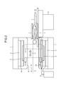
- FIG. 2 is a schematic diagram illustrating an example of the moving mechanism of a PET detector according to the first embodiment.
- the PET detector 13 is disposed between the transmitting radio frequency coil 5 and the bore cover 19.
- the moving mechanism 20 is also disposed between the transmitting radio frequency coil 5 and the bore cover 19.
- the moving mechanism 20 causes the PET detector 13 to move in a gantry along the axial direction of the bore.
- the moving mechanism 20 causes the PET detector 13 to move, in a space formed between the transmitting radio frequency coil 5 and the bore cover 19, in the Z-axis direction of the bore B (in a direction indicated by the double-headed arrow A illustrated in FIG. 2 ).
- the moving mechanism 20 causes the PET detector 13 to move by being driven by a driving device 21, for example.
- the moving mechanism 20 is composed of at least two rotational shafts disposed along the axial direction of the bore B at the ends of the gantry including the static magnetic field magnet 1, the gradient coil 3, the transmitting radio frequency coil 5, and the bore cover 19, and a belt wound between the rotational shafts.
- the driving device 21 rotationally drives the rotational shafts, so that the PET detector 13 fixed to a part of the belt is moved in the Z-axis direction of the bore B.
- the PET-MRI apparatus is described as above.
- the positions of the PET detectors are fixed in many cases.
- the PET detectors are removable. Even in such cases, the positions of most of the PET detectors are fixed.
- PET-MRI apparatuses have been also developed in which two PET detectors are disposed spaced apart from each other, the PET detectors need not always be disposed around the imaging center and may be allowed to be somewhat off the imaging center.
- imaging by the MRI can be performed only at the central position in the axial direction of the bore
- imaging by the PET is executable at any position in the axial direction of the bore. Since the imaging by the MRI and the imaging by the PET differ from each other in data acquisition time ,that the position of the object in PET imaging is always the center of the magnetic field is in some cases inconvenient for constructing an imaging protocol combining MRI imaging and PET imaging.
- the PET detector 13 is caused to move in the axial direction of the bore by the moving mechanism 20, and thereby the PET detector 13 can be moved to a position distant from the magnetic field center.
- effect of interference between the PET detector and the magnetic field on data acquisition can be lessened.
- a degree of freedom in establishing the imaging protocol in a combination of MRI and PET can be increased.
- the moving mechanism of the PET detector is not limited to the example illustrated in FIG. 2 .
- Other examples of the moving mechanism are described below as second to eighth embodiments.
- FIG. 3 is a schematic diagram illustrating an example of the moving mechanism of a PET detector according to a second embodiment.
- the PET detector 13 is disposed between the gradient coil 3 and the radio frequency shield 18.
- the moving mechanism 20 is also disposed between the gradient coil 3 and the radio frequency shield 18.
- the moving mechanism 20 causes the PET detector 13 to move in the gantry along the axial direction of the bore.
- the moving mechanism 20 by being driven by the driving device 21, causes the PET detector 13 to move in a space formed between the gradient coil 3 and the radio frequency shield 18 in the Z-axis direction of the bore (in a direction indicated by the double-headed arrow A illustrated in FIG. 3 ).
- FIG. 4 is a schematic diagram illustrating an example of the moving mechanism of a PET detector according to a third embodiment.
- the couchtop is divided into the couchtop 2a on which the object P is placed and a couchtop 2b that supports the couchtop 2a from the lower side of the couchtop 2a.
- the couchtop 2a is placed on the couchtop 2b such that the position of the couchtop 2a relative to the couchtop 2b is not changed.
- the couch 2 causes the couchtop 2b to move into the bore B while the couchtop 2a is placed on the couchtop 2b (in a direction indicated by the double-headed arrow A1 illustrated in FIG. 4 ).
- the PET detector 13 is provided to the couchtop such that it is movable in the longitudinal direction of the couchtop.
- the PET detector 13 is disposed to a groove formed on the couchtop 2b along the longitudinal direction of the couchtop 2b, and supported such that it is movable in the longitudinal direction of the couchtop 2b.
- the moving mechanism 20 is provided in the couchtop.
- the moving mechanism 20 is driven by the driving device 21 and causes the PET detector 13 to move in the longitudinal direction of the couchtop 2b (in a direction indicated by the double-headed arrow A2 illustrated in FIG. 4 ).
- the PET detector 13 it is also possible to cause the PET detector 13 to move in the Z-axis direction of the bore B along with the movement of the couchtop 2b, and it is also possible to cause the PET detector 13 to move in the Z-axis direction of the bore B along the longitudinal direction of the couchtop 2b even if the position of the couchtop 2b is fixed.
- the PET detector 13 may be provided to the couchtop 2b in a detachable manner. In such a case, a connector connecting a control line and a power source line of the PET detector 13 is disposed to the couchtop 2b, for example.
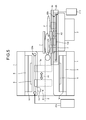
- FIGS. 5 and 6 are schematic diagrams illustrating an example of the moving mechanism of a PET detector according to a fourth embodiment.
- the couchtop is divided into the couchtop 2a on which the object P is placed and the couchtop 2b on which the couchtop 2a is placed, in the same manner as the third embodiment.
- the positional relation between the couchtop 2a and the couchtop 2b, and the operation of the couch 2 are the same as those in the third embodiment.
- the PET detector is divided into a first PET detector 13a and a second PET detector 13b.
- the first PET detector 13a is disposed around the bore B while the second PET detector 13b is disposed to the couchtop.
- the moving mechanism is also divided into a first moving mechanism 20a and a second moving mechanism 20b.
- the first moving mechanism 20a causes the first PET detector 13a to move in the gantry along the axial direction of the bore.
- the first moving mechanism 20a is driven by a driving device 21 a and causes, around the bore B, the first PET detector 13a to move along the Z-axis direction of the bore B (in a direction indicated by the double-headed arrow A1 illustrated in FIG. 5 ).
- the second moving mechanism 20b is driven by a driving device 21 b and causes the second PET detector 13b to move along the longitudinal direction of the couchtop 2b (in a direction indicated by the double-headed arrow A2 illustrated in FIG. 5 ).
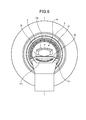
- FIG. 6 illustrates a view of the first PET detector 13a and the second PET detector 13b and their surroundings when viewed from the Z-axis direction of the bore B.
- the first PET detector 13a and the second PET detector 13b are each formed in an arc shape.
- the first PET detector 13a is disposed on the upper side of the bore B such that the inner circumference side of the arc faces the bore B side.
- the second PET detector 13b is disposed on the couchtop 2b such that the inner circumference side of the arc faces the bore B side.
- the PET detector is divided into the first PET detector 13a provided on the gantry side and the second PET detector 13b provided on the couchtop side, and they can be caused to move independently from each other in the Z-axis direction of the bore B.
- Data acquisition is performed when the couchtop 2b is inserted in the bore B and the position of the first PET detector 13a and the position of the second PET detector 13b become the same position in the Z-axis direction of the bore B.
- the second PET detector 13b may be provided to the couchtop 2b in a detachable manner.
- a connector connecting a control line and a power source line of the second PET detector 13b is disposed to the couchtop 2b, for example.
- the first PET detector 13a may be controlled such that it cannot move at least in a time period when the object P is inserted.
- FIG. 7 is a schematic diagram illustrating an example of the moving mechanism of a PET detector according to a fifth embodiment.
- the first moving mechanism 20a illustrated in FIG. 5 causes the first PET detector 13a to move additionally in the up-down direction with an up-down moving mechanism 20d (in a direction indicated by the double-headed arrow A illustrated in FIG. 7 ).
- the first moving mechanism 20a also causes the first PET detector 13a to move in the gantry along the axial direction of the bore.
- the first PET detector 13a can be caused to move not only in the Z-axis direction of the bore B but also in the up-down direction.
- the distance between the two PET detectors can be adjusted in accordance with the body size of the object P, for example.
- FIG. 8 is a schematic diagram illustrating an example of the moving mechanism of a PET detector according to a sixth embodiment.
- the PET detector 13 is provided such that it can move outside the static magnetic field magnet 1.
- the bore cover 19 is formed such that it protrudes from the static magnetic field magnet 1 on a side where the couch 2 is not placed.
- the moving mechanism 20 is provided such that it extends in a space formed inside the protruding portion of the bore cover 19.
- the moving mechanism 20 causes the PET detector 13 to move along the Z-axis direction of the bore B (in a direction indicated by the double-headed arrow A illustrated in FIG. 8 ).
- the moving mechanism 20 causes the PET detector 13 to move in the gantry along the axial direction of the bore.
- the moving mechanism 20 causes the PET detector 13 to move inside the portion protruding from the static magnetic field magnet 1 of the bore cover 19, thereby making it possible to move the PET detector 13 outside the static magnetic field magnet 1.
- the PET detector 13 can be caused to move outside the static magnetic field magnet 1, effect of interference between the first PET detector 13 and the magnetic field on data acquisition can be surely lessened.
- FIG. 9 is a schematic diagram illustrating an example of the moving mechanism of a PET detector according to a seventh embodiment.
- the PET detector is divided into the first PET detector 13a and the second PET detector 13b.
- the first PET detector 13a and the second PET detector 13b are disposed such that they face to each other with respect to the Z-axis of the bore B interposed therebetween.
- a retainer 30a is provided that retains the first PET detector 13a such that the first PET detector 13a is movable in the bore B.
- the retainer 30a causes the first PET detector 13a to move in the gantry along the axial direction of the bore.
- the retainer 30a causes the first PET detector 13a to move along the Z-axis direction of the bore B (in a direction indicated by the double-headed arrow A1 illustrated in FIG. 9 ).
- the retainer 30a can be realized using an arm having a plurality of joints.
- the retainer 30a may cause the first PET detector 13a to move by being driven by a driving device or may cause the first PET detector 13a to move by being manually operated by an operator.
- the moving mechanism 20 causes the second PET detector 13b to move in the gantry along the axial direction of the bore.
- the moving mechanism 20 causes the second PET detector 13b to move along the Z-axis direction of the bore B in coordination with the movement of the first PET detector 13a (in a direction indicated by the double-headed arrow A2 illustrated in FIG. 9 ).
- the second PET detector 13b has a width larger than that of the first PET detector 13a in the Z-axis direction of the bore B.
- the position of the second PET detector 13b may be fixed, thereby making it possible to eliminate the moving mechanism 20.
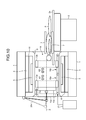
- FIG. 10 is a schematic diagram illustrating an example of the moving mechanism of a PET detector according to an eighth embodiment. As illustrated in FIG. 10 , in the eighth embodiment, included are the first PET detector 13a, the second PET detector 13b, and a PET detector 13c.
- the first PET detector 13a and the second PET detector 13b are each formed in a ring shape and each have a detection surface on the inner circumference of the ring.
- the first PET detector 13a and the second PET detector 13b are disposed side by side along the Z-axis of the bore B.
- the first PET detector 13a is caused to move in the Z-axis direction of the bore B by the first moving mechanism 20a (in a direction indicated by the double-headed arrow A1 illustrated in FIG. 10 ) while the second PET detector 13b is caused to move in the Z-axis direction of the bore B by the second moving mechanism 20b (in a direction indicated by the double-headed arrow A2 illustrated in FIG. 10 ).
- the first PET detector 13a and the second PET detector 13b are caused to move in the gantry by a moving mechanism 10a.
- the distance between the first PET detector 13a and the second PET detector 13b are arbitrarily adjusted.
- the PET detector 13c has a detection surface that is approximately perpendicular to the Z-axis direction of the bore B.
- the PET detector 13c is caused to move along the Z-axis direction of the bore B by a moving mechanism 20c (in a direction indicated by the double-headed arrow A3 illustrated in FIG. 10 ).
- the PET detector 13c is also caused to move in the gantry by the moving mechanism 20c.
- the moving mechanism 20c causes the PET detector 13c to move to a position adjacent to the first PET detector 13a in the Z-axis direction of the bore B.
- FIGS. 11 and 12 are schematic diagrams each illustrating an example of effective imaging regions of the PET-MRI apparatus according to the eighth embodiment.
- the PET detectors and the bore cover 19 are illustrated but illustration of other components is omitted.
- FIG. 11 illustrates an example of effective imaging regions when the PET detector 13c (not illustrated) is distantly separated from the first PET detector 13a.
- a region 31 surrounded by the inner circumference of the first PET detector 13a, a region 32 surrounded by the inner circumference of the second PET detector 13b, and a region 33 formed between the inner circumference of the first PET detector 13a and the inner circumference of the second PET detector 13b are the respective effective imaging regions in which PET images can be taken.
- a straight line 34 illustrated in FIG. 11 indicates the central position in the axial direction of the bore B and a spherical region 35 illustrated in FIG. 11 is the effective imaging region of MR images.
- FIG. 12 illustrates the effective imaging regions when the PET detector 13c is placed adjacent to the first PET detector 13a.
- a region 36 formed between the detection surface of the PET detector 13c and the inner circumference of the first PET detector 13a, and a region 37 formed between the detection surface of the PET detector 13c and the inner circumference of the second PET detector 13b serve as the additional effective imaging regions in which PET images can be taken.
- FIGS. 11 and 12 each illustrate an example when the head portion of the object P is disposed inside the first PET detector 13a. Similar effect can be obtained also in a case where the foot portion of the object P is disposed there. That is, imaging performed by placing the PET detector 13c adjacent to the first PET detector 13a is preferable when an end portion of the object P is imaged.
- the moving mechanisms of the PET detectors are described.
- the position of the PET detector caused to move by the moving mechanisms may be detected and the detected position of the PET detector may be displayed on a display unit.
- the computer 10 illustrated in FIG. 1 acquires the amount of movement from the driving device driving the moving mechanism or the position of the PET detector from a position sensor provided to the PET detector, for example.
- the computer 10 causes the display 12 to display the detected position of the PET detector together with a PET image and an MR image, for example. Meanwhile, the computer 10 may display the position of the magnetic field center together with them.
- the examples are described in which the moving mechanisms are caused to be driven by the driving devices.
- the moving mechanism may be manually operated by an operator.
- the fourth embodiment illustrated in FIG. 5 may be combined with the sixth embodiment illustrated in FIG. 8 so as to provide the first PET detector 13a disposed on the upper side of the bore B in such a manner that the first PET detector 13a can move outside the static magnetic field magnet 1.
- the bore cover 19 is formed such that it protrudes from the static magnetic field magnet 1 on the side where the couch 2 is not placed, and the first moving mechanism 20a is provided such that it extends in a space formed inside the protruding portion of the bore cover 19.
- the respective embodiments described above can lessen effects of interference between the PET detector and the magnetic field on data acquisition.
Landscapes
- Health & Medical Sciences (AREA)
- Life Sciences & Earth Sciences (AREA)
- Physics & Mathematics (AREA)
- Nuclear Medicine, Radiotherapy & Molecular Imaging (AREA)
- Engineering & Computer Science (AREA)
- General Health & Medical Sciences (AREA)
- Radiology & Medical Imaging (AREA)
- Molecular Biology (AREA)
- Medical Informatics (AREA)
- High Energy & Nuclear Physics (AREA)
- Biomedical Technology (AREA)
- Biophysics (AREA)
- Surgery (AREA)
- Public Health (AREA)
- Veterinary Medicine (AREA)
- Heart & Thoracic Surgery (AREA)
- Pathology (AREA)
- Animal Behavior & Ethology (AREA)
- General Physics & Mathematics (AREA)
- Condensed Matter Physics & Semiconductors (AREA)
- Pulmonology (AREA)
- Theoretical Computer Science (AREA)
- Spectroscopy & Molecular Physics (AREA)
- Optics & Photonics (AREA)
- Nuclear Medicine (AREA)
- Magnetic Resonance Imaging Apparatus (AREA)
Abstract
Description
- Embodiments of the present invention relate to a positron emission tomography (PET)-magnetic resonance imaging (MRI) apparatus.
- In recent years, PET-MRI apparatuses having a combination of positron emission tomography (PET) apparatuses and magnetic resonance imaging (MRI) apparatuses have been made into products. Generally, the PET-MRI apparatuses are realized by attaching PET detectors to the MRI apparatuses, and in many cases, the positions of the PET detectors are fixed. However, when the PET detectors are fixed in the vicinity of magnetic field centers of the MRI apparatuses, the PET detectors may interfere with high power radio frequency (RF) magnetic fields generated in the magnetic field centers and radio frequency coils (RF coils) detecting generated magnetic resonance signals, which may cause data acquisition not to be properly made.
- Patent Literature 1: Published Japanese Translation of
PCT International Publication No. 2008-525161 - An object of the present invention is to provide a PET-MRI apparatus that can reduce influence on data acquisition due to the interference of the PET detectors with the high power RF magnetic fields generated in the magnetic field centers and the radio frequency coils detecting generated magnetic resonance signals.
- A positron emission tomography (PET)-magnetic resonance imaging (MRI) apparatus according to the present embodiment comprises a static magnetic field magnet, a gradient coil, a radio frequency coil, a PET detector and a moving mechanism. The static magnetic field magnet generates a static magnetic field in a bore having an approximately cylindrical shape. The gradient coil is disposed on an inner circumference side of the static magnetic field magnet and applies a gradient magnetic field to an object disposed in the bore. The radio frequency coil is disposed on an inner circumference side of the gradient coil and applies a radio frequency magnetic field to the object. The PET detector detects gamma rays emitted from a positron-emitting radionuclide injected into the object. The moving mechanism causes the PET detector to move in the gantry along the axial direction of the bore.
-
-
FIG. 1 is a schematic diagram illustrating the overall structure of a PET-MRI apparatus according to a first embodiment. -
FIG. 2 is a schematic diagram illustrating an example of the moving mechanism of a PET detector according to the first embodiment. -
FIG. 3 is a schematic diagram illustrating an example of the moving mechanism of a PET detector according to a second embodiment. -
FIG. 4 is a schematic diagram illustrating an example of the moving mechanism of a PET detector according to a third embodiment. -
FIG. 5 is a first schematic diagram illustrating an example of the moving mechanism of a PET detector according to a fourth embodiment. -
FIG. 6 is a second schematic diagram illustrating the example of the moving mechanism of the PET detector according to the fourth embodiment. -
FIG. 7 is a schematic diagram illustrating an example of the moving mechanism of a PET detector according to a fifth embodiment. -
FIG. 8 is a schematic diagram illustrating an example of the moving mechanism of a PET detector according to a sixth embodiment. -
FIG. 9 is a schematic diagram illustrating an example of the moving mechanism of a PET detector according to a seventh embodiment. -
FIG. 10 is a schematic diagram illustrating an example of the moving mechanism of a PET detector according to an eighth embodiment. -
FIG. 11 is a first schematic diagram illustrating an example of effective imaging regions of the PET detector according to the eighth embodiment. -
FIG. 12 is a second schematic diagram illustrating an example of the effective imaging regions of the PET detector according to the eighth embodiment. - Embodiments of a PET-MRI apparatus are described below with reference to the accompanying drawings.
-
FIG. 1 is a schematic diagram illustrating the overall structure of a PET-MRI apparatus according to a first embodiment. As illustrated inFIG. 1 , a PET-MRI apparatus 100 according to the first embodiment includes a staticmagnetic field magnet 1, acouch 2, agradient coil 3, a gradient coil driving circuit 4, a transmittingradio frequency coil 5, a transmitter 6, a receivingradio frequency coil 7, areceiver 8, an MRdata acquisition unit 9, a computer(a position detection unit) 10, a console 11, a display 12, aPET detector 13,signal lines 14, a PETdata acquisition unit 15, a PETimage reconstruction unit 16, asequence controller 17, aradio frequency shield 18, and abore cover 19. - The static
magnetic field magnet 1 generates a static magnetic field in a bore B having an approximately cylindrical shape. Thecouch 2 has acouchtop 2a on which an object P is placed. When the object P is imaged, thecouch 2 causes thecouchtop 2a to move into the bore B with the longitudinal direction of thecouchtop 2a being along the axial direction of the bore B, thereby moving the object P into the static magnetic field. - The
gradient coil 3 applies gradient magnetic fields Gx, Gy, and Gz on the object P. The magnetic field intensities of the gradient magnetic fields Gx, Gy, and Gz change linearly in the X, Y, and Z directions, respectively. Thegradient coil 3 is formed in an approximately cylindrical shape and disposed on an inner circumference side of the staticmagnetic field magnet 1. The gradient coil driving circuit 4 drives thegradient coil 3 under control of thesequence controller 17. - The transmitting
radio frequency coil 5 applies a radio frequency magnetic field on the object P placed in the static magnetic field on the basis of a radio frequency pulse transmitted from the transmitter 6. The transmittingradio frequency coil 5 is formed in an approximately cylindrical shape and disposed on an inner circumference side of thegradient coil 3. The transmitter 6 transmits the radio frequency pulse to the transmittingradio frequency coil 5 under control of thesequence controller 17. - The receiving
radio frequency coil 7 detects a magnetic resonance signal emitted from the object P due to the application of the radio frequency magnetic field and the gradient magnetic field. For example, the receivingradio frequency coil 7 is a surface coil disposed on the surface of the object P depending on a portion to be imaged. For example, when a body portion of the object P is imaged, two receivingradio frequency coils 7 are disposed on the upper part and the lower part of the object P. Thereceiver 8 receives the magnetic resonance signal detected by the receivingradio frequency coil 7 and sends the received magnetic resonance signal to the MRdata acquisition unit 9, under control of thesequence controller 17. - The MR
data acquisition unit 9 acquires the magnetic resonance signal sent from thereceiver 8, under control of thesequence controller 17. The MRdata acquisition unit 9 amplifies the acquired magnetic resonance signal and performs detection on the amplified signal. Thereafter, the MR data acquisition unit 9 A/D-converts the signal after the detection and sends the converted signal to thecomputer 10. Thecomputer 10, which is controlled by the console 11, reconstructs an MR image on the basis of the magnetic resonance signal sent from the MRdata acquisition unit 9. Thecomputer 10 causes the display 12 to display the reconstructed MR image. - The
PET detector 13 detects, as counting information, gamma rays (including annihilation radiation) emitted from positron-emitting radionuclides injected into the object P. ThePET detector 13 is formed in a ring shape and disposed on an outer circumference side of the transmittingradio frequency coil 5. For example, thePET detector 13 is formed by arranging detector modules including scintillators and photodetectors in a ring shape. Examples of the scintillator include lutetium yttrium oxyorthosilicate (LYSO), lutetium oxyorthosilicate (LSO), and lutetium gadolinium oxyorthosilicate (LGSO). The photodetector is, for example, a semiconductor detector such as an avalanche photodiode (APD) element or a SiPM (Silicon Photomultiplier), or a photomultiplier tube (PMT). ThePET detector 13 sends the detected counting information to the PETdata acquisition unit 15 through thesignal lines 14. - The PET
data acquisition unit 15 produces simultaneous counting information under control of thesequence controller 17. The PETdata acquisition unit 15 produces, as the simultaneous counting information, a combination of counting information of gamma rays that are emitted from the positron-emitting radionuclides and approximately simultaneously detected, using the counting information of the gamma rays detected by thePET detector 13. - The PET
image reconstruction unit 16 reconstructs a PET image using the simultaneous counting information produced by the PETdata acquisition unit 15 as projection data. The PET image reconstructed by the PETimage reconstruction unit 16 is transmitted to thecomputer 10 and displayed on the display 12. Thesequence controller 17 receives, from thecomputer 10, information on various types of imaging sequences executed when the object is imaged and controls the above-described components. - The
radio frequency shield 18 is disposed between thegradient coil 3 and the transmittingradio frequency coil 5 and shields the radio frequency magnetic field generated by the transmittingradio frequency coil 5. The bore cover 19 is a cover covering an inner circumference side of the transmittingradio frequency coil 5. The bore cover 19 forms the bore B, which is a space having an approximately cylindrical shape, inside an approximately cylindrical structure composed of the staticmagnetic field magnet 1, thegradient coil 3, theradio frequency shield 18, and the transmittingradio frequency coil 5. - The PET-
MRI apparatus 100 according to the first embodiment further includes a movingmechanism 20 that causes thePET detector 13 to move along the axial direction of the bore, in addition to the above-described structure. -
FIG. 2 is a schematic diagram illustrating an example of the moving mechanism of a PET detector according to the first embodiment. As illustrated inFIG. 2 , in the first embodiment, thePET detector 13 is disposed between the transmittingradio frequency coil 5 and thebore cover 19. The movingmechanism 20 is also disposed between the transmittingradio frequency coil 5 and thebore cover 19. - As illustrated in
FIG. 2 , the movingmechanism 20 causes thePET detector 13 to move in a gantry along the axial direction of the bore. For example, the movingmechanism 20 causes thePET detector 13 to move, in a space formed between the transmittingradio frequency coil 5 and thebore cover 19, in the Z-axis direction of the bore B (in a direction indicated by the double-headed arrow A illustrated inFIG. 2 ). The movingmechanism 20 causes thePET detector 13 to move by being driven by a drivingdevice 21, for example. - For example, the moving
mechanism 20 is composed of at least two rotational shafts disposed along the axial direction of the bore B at the ends of the gantry including the staticmagnetic field magnet 1, thegradient coil 3, the transmittingradio frequency coil 5, and thebore cover 19, and a belt wound between the rotational shafts. The drivingdevice 21 rotationally drives the rotational shafts, so that thePET detector 13 fixed to a part of the belt is moved in the Z-axis direction of the bore B. - The PET-MRI apparatus according to the first embodiment is described as above. In the PET-MRI apparatuses having been made into products in recent years, the positions of the PET detectors are fixed in many cases. In some of the PET-MRI apparatuses, the PET detectors are removable. Even in such cases, the positions of most of the PET detectors are fixed. Although PET-MRI apparatuses have been also developed in which two PET detectors are disposed spaced apart from each other, the PET detectors need not always be disposed around the imaging center and may be allowed to be somewhat off the imaging center.
- In fact, if the PET detectors and the radio frequency coil are in different positions in the axial direction of the bore, it would be more preferable for data acquisition, as interference would become smaller. Although imaging by the MRI can be performed only at the central position in the axial direction of the bore, imaging by the PET is executable at any position in the axial direction of the bore. Since the imaging by the MRI and the imaging by the PET differ from each other in data acquisition time ,that the position of the object in PET imaging is always the center of the magnetic field is in some cases inconvenient for constructing an imaging protocol combining MRI imaging and PET imaging.
- In contrast, in the PET-
MRI apparatus 100 according to the first embodiment, thePET detector 13 is caused to move in the axial direction of the bore by the movingmechanism 20, and thereby thePET detector 13 can be moved to a position distant from the magnetic field center. As a result, effect of interference between the PET detector and the magnetic field on data acquisition can be lessened. In addition, a degree of freedom in establishing the imaging protocol in a combination of MRI and PET can be increased. - The moving mechanism of the PET detector is not limited to the example illustrated in
FIG. 2 . Other examples of the moving mechanism are described below as second to eighth embodiments. -
FIG. 3 is a schematic diagram illustrating an example of the moving mechanism of a PET detector according to a second embodiment. As illustrated inFIG. 3 , in the second embodiment, thePET detector 13 is disposed between thegradient coil 3 and theradio frequency shield 18. The movingmechanism 20 is also disposed between thegradient coil 3 and theradio frequency shield 18. As illustrated inFIG. 3 , the movingmechanism 20 causes thePET detector 13 to move in the gantry along the axial direction of the bore. For example, the movingmechanism 20, by being driven by the drivingdevice 21, causes thePET detector 13 to move in a space formed between thegradient coil 3 and theradio frequency shield 18 in the Z-axis direction of the bore (in a direction indicated by the double-headed arrow A illustrated inFIG. 3 ). -
FIG. 4 is a schematic diagram illustrating an example of the moving mechanism of a PET detector according to a third embodiment. As illustrated inFIG. 4 , in the third embodiment, the couchtop is divided into thecouchtop 2a on which the object P is placed and acouchtop 2b that supports thecouchtop 2a from the lower side of thecouchtop 2a. Thecouchtop 2a is placed on thecouchtop 2b such that the position of thecouchtop 2a relative to thecouchtop 2b is not changed. Thecouch 2 causes thecouchtop 2b to move into the bore B while thecouchtop 2a is placed on thecouchtop 2b (in a direction indicated by the double-headed arrow A1 illustrated inFIG. 4 ). - The
PET detector 13 is provided to the couchtop such that it is movable in the longitudinal direction of the couchtop. For example, thePET detector 13 is disposed to a groove formed on thecouchtop 2b along the longitudinal direction of thecouchtop 2b, and supported such that it is movable in the longitudinal direction of thecouchtop 2b. The movingmechanism 20 is provided in the couchtop. For example, the movingmechanism 20 is driven by the drivingdevice 21 and causes thePET detector 13 to move in the longitudinal direction of thecouchtop 2b (in a direction indicated by the double-headed arrow A2 illustrated inFIG. 4 ). - That is, in the third embodiment, it is also possible to cause the
PET detector 13 to move in the Z-axis direction of the bore B along with the movement of thecouchtop 2b, and it is also possible to cause thePET detector 13 to move in the Z-axis direction of the bore B along the longitudinal direction of thecouchtop 2b even if the position of thecouchtop 2b is fixed. ThePET detector 13 may be provided to thecouchtop 2b in a detachable manner. In such a case, a connector connecting a control line and a power source line of thePET detector 13 is disposed to thecouchtop 2b, for example. -
FIGS. 5 and6 are schematic diagrams illustrating an example of the moving mechanism of a PET detector according to a fourth embodiment. As illustrated inFIG. 5 , in the fourth embodiment, the couchtop is divided into thecouchtop 2a on which the object P is placed and thecouchtop 2b on which thecouchtop 2a is placed, in the same manner as the third embodiment. The positional relation between thecouchtop 2a and thecouchtop 2b, and the operation of thecouch 2 are the same as those in the third embodiment. - The PET detector is divided into a
first PET detector 13a and asecond PET detector 13b. Thefirst PET detector 13a is disposed around the bore B while thesecond PET detector 13b is disposed to the couchtop. The moving mechanism is also divided into a first movingmechanism 20a and asecond moving mechanism 20b. As illustrated inFIG. 5 , the first movingmechanism 20a causes thefirst PET detector 13a to move in the gantry along the axial direction of the bore. For example, the first movingmechanism 20a is driven by a drivingdevice 21 a and causes, around the bore B, thefirst PET detector 13a to move along the Z-axis direction of the bore B (in a direction indicated by the double-headed arrow A1 illustrated inFIG. 5 ). For example, thesecond moving mechanism 20b is driven by a drivingdevice 21 b and causes thesecond PET detector 13b to move along the longitudinal direction of thecouchtop 2b (in a direction indicated by the double-headed arrow A2 illustrated inFIG. 5 ). -
FIG. 6 illustrates a view of thefirst PET detector 13a and thesecond PET detector 13b and their surroundings when viewed from the Z-axis direction of the bore B. As illustrated inFIG. 6 , thefirst PET detector 13a and thesecond PET detector 13b are each formed in an arc shape. Thefirst PET detector 13a is disposed on the upper side of the bore B such that the inner circumference side of the arc faces the bore B side. Thesecond PET detector 13b is disposed on thecouchtop 2b such that the inner circumference side of the arc faces the bore B side. - That is, in the fourth embodiment, the PET detector is divided into the
first PET detector 13a provided on the gantry side and thesecond PET detector 13b provided on the couchtop side, and they can be caused to move independently from each other in the Z-axis direction of the bore B. Data acquisition is performed when thecouchtop 2b is inserted in the bore B and the position of thefirst PET detector 13a and the position of thesecond PET detector 13b become the same position in the Z-axis direction of the bore B. - The
second PET detector 13b may be provided to thecouchtop 2b in a detachable manner. In such a case, a connector connecting a control line and a power source line of thesecond PET detector 13b is disposed to thecouchtop 2b, for example. Thefirst PET detector 13a may be controlled such that it cannot move at least in a time period when the object P is inserted. -
FIG. 7 is a schematic diagram illustrating an example of the moving mechanism of a PET detector according to a fifth embodiment. As illustrated inFIG. 7 , in the fifth embodiment, the first movingmechanism 20a illustrated inFIG. 5 causes thefirst PET detector 13a to move additionally in the up-down direction with an up-down movingmechanism 20d (in a direction indicated by the double-headed arrow A illustrated inFIG. 7 ). As illustrated inFIG. 7 , the first movingmechanism 20a also causes thefirst PET detector 13a to move in the gantry along the axial direction of the bore. - That is, in the fifth embodiment, the
first PET detector 13a can be caused to move not only in the Z-axis direction of the bore B but also in the up-down direction. As a result, the distance between the two PET detectors can be adjusted in accordance with the body size of the object P, for example. -
FIG. 8 is a schematic diagram illustrating an example of the moving mechanism of a PET detector according to a sixth embodiment. As illustrated inFIG. 8 , in the sixth embodiment, thePET detector 13 is provided such that it can move outside the staticmagnetic field magnet 1. For example, as illustrated inFIG. 8 , thebore cover 19 is formed such that it protrudes from the staticmagnetic field magnet 1 on a side where thecouch 2 is not placed. - The moving
mechanism 20 is provided such that it extends in a space formed inside the protruding portion of thebore cover 19. The movingmechanism 20 causes thePET detector 13 to move along the Z-axis direction of the bore B (in a direction indicated by the double-headed arrow A illustrated inFIG. 8 ). In addition, as illustrated inFIG. 8 , the movingmechanism 20 causes thePET detector 13 to move in the gantry along the axial direction of the bore. As a result, the movingmechanism 20 causes thePET detector 13 to move inside the portion protruding from the staticmagnetic field magnet 1 of thebore cover 19, thereby making it possible to move thePET detector 13 outside the staticmagnetic field magnet 1. - That is, in the sixth embodiment, because the
PET detector 13 can be caused to move outside the staticmagnetic field magnet 1, effect of interference between thefirst PET detector 13 and the magnetic field on data acquisition can be surely lessened. -
FIG. 9 is a schematic diagram illustrating an example of the moving mechanism of a PET detector according to a seventh embodiment. As illustrated inFIG. 9 , in the seventh embodiment, the PET detector is divided into thefirst PET detector 13a and thesecond PET detector 13b. Thefirst PET detector 13a and thesecond PET detector 13b are disposed such that they face to each other with respect to the Z-axis of the bore B interposed therebetween. - For example, as illustrated in
FIG. 9 , aretainer 30a is provided that retains thefirst PET detector 13a such that thefirst PET detector 13a is movable in the bore B. As illustrated inFIG. 9 , theretainer 30a causes thefirst PET detector 13a to move in the gantry along the axial direction of the bore. For example, theretainer 30a causes thefirst PET detector 13a to move along the Z-axis direction of the bore B (in a direction indicated by the double-headed arrow A1 illustrated inFIG. 9 ). For example, theretainer 30a can be realized using an arm having a plurality of joints. Theretainer 30a may cause thefirst PET detector 13a to move by being driven by a driving device or may cause thefirst PET detector 13a to move by being manually operated by an operator. - As illustrated in
FIG. 9 , the movingmechanism 20 causes thesecond PET detector 13b to move in the gantry along the axial direction of the bore. For example, the movingmechanism 20 causes thesecond PET detector 13b to move along the Z-axis direction of the bore B in coordination with the movement of thefirst PET detector 13a (in a direction indicated by the double-headed arrow A2 illustrated inFIG. 9 ). Thesecond PET detector 13b has a width larger than that of thefirst PET detector 13a in the Z-axis direction of the bore B. When the width of thesecond PET detector 13b in the Z-axis direction of the bore B is sufficiently large, the position of thesecond PET detector 13b may be fixed, thereby making it possible to eliminate the movingmechanism 20. -
FIG. 10 is a schematic diagram illustrating an example of the moving mechanism of a PET detector according to an eighth embodiment. As illustrated inFIG. 10 , in the eighth embodiment, included are thefirst PET detector 13a, thesecond PET detector 13b, and aPET detector 13c. - The
first PET detector 13a and thesecond PET detector 13b are each formed in a ring shape and each have a detection surface on the inner circumference of the ring. Thefirst PET detector 13a and thesecond PET detector 13b are disposed side by side along the Z-axis of the bore B. Thefirst PET detector 13a is caused to move in the Z-axis direction of the bore B by the first movingmechanism 20a (in a direction indicated by the double-headed arrow A1 illustrated inFIG. 10 ) while thesecond PET detector 13b is caused to move in the Z-axis direction of the bore B by thesecond moving mechanism 20b (in a direction indicated by the double-headed arrow A2 illustrated inFIG. 10 ). As illustrated inFIG. 10 , thefirst PET detector 13a and thesecond PET detector 13b are caused to move in the gantry by a moving mechanism 10a. As a result, the distance between thefirst PET detector 13a and thesecond PET detector 13b are arbitrarily adjusted. - The
PET detector 13c has a detection surface that is approximately perpendicular to the Z-axis direction of the bore B. ThePET detector 13c is caused to move along the Z-axis direction of the bore B by a movingmechanism 20c (in a direction indicated by the double-headed arrow A3 illustrated inFIG. 10 ). As illustrated inFIG. 10 , thePET detector 13c is also caused to move in the gantry by the movingmechanism 20c. The movingmechanism 20c causes thePET detector 13c to move to a position adjacent to thefirst PET detector 13a in the Z-axis direction of the bore B. -
FIGS. 11 and 12 are schematic diagrams each illustrating an example of effective imaging regions of the PET-MRI apparatus according to the eighth embodiment. InFIGS. 11 and 12 , the PET detectors and thebore cover 19 are illustrated but illustration of other components is omitted. -
FIG. 11 illustrates an example of effective imaging regions when thePET detector 13c (not illustrated) is distantly separated from thefirst PET detector 13a. In this case, aregion 31 surrounded by the inner circumference of thefirst PET detector 13a, aregion 32 surrounded by the inner circumference of thesecond PET detector 13b, and aregion 33 formed between the inner circumference of thefirst PET detector 13a and the inner circumference of thesecond PET detector 13b are the respective effective imaging regions in which PET images can be taken. Astraight line 34 illustrated inFIG. 11 indicates the central position in the axial direction of the bore B and aspherical region 35 illustrated inFIG. 11 is the effective imaging region of MR images. -
FIG. 12 illustrates the effective imaging regions when thePET detector 13c is placed adjacent to thefirst PET detector 13a. In this case, in addition to theregions 31 to 33 illustrated inFIG. 11 , aregion 36 formed between the detection surface of thePET detector 13c and the inner circumference of thefirst PET detector 13a, and aregion 37 formed between the detection surface of thePET detector 13c and the inner circumference of thesecond PET detector 13b serve as the additional effective imaging regions in which PET images can be taken. - As is obvious also from
FIGS. 11 and 12 , by placing thePET detector 13c adjacent to thefirst PET detector 13a, the detection probability of gamma rays emitted from the object P inside thefirst PET detector 13a can be increased. As a result, the spatial resolution of PET images inside thefirst PET detector 13a can be increased.FIGS. 11 and 12 each illustrate an example when the head portion of the object P is disposed inside thefirst PET detector 13a. Similar effect can be obtained also in a case where the foot portion of the object P is disposed there. That is, imaging performed by placing thePET detector 13c adjacent to thefirst PET detector 13a is preferable when an end portion of the object P is imaged. - In the above-described embodiments, the moving mechanisms of the PET detectors are described. For example, the position of the PET detector caused to move by the moving mechanisms may be detected and the detected position of the PET detector may be displayed on a display unit. In such a case, the
computer 10 illustrated inFIG. 1 acquires the amount of movement from the driving device driving the moving mechanism or the position of the PET detector from a position sensor provided to the PET detector, for example. Then, thecomputer 10 causes the display 12 to display the detected position of the PET detector together with a PET image and an MR image, for example. Meanwhile, thecomputer 10 may display the position of the magnetic field center together with them. - In the above-described embodiments, the examples are described in which the moving mechanisms are caused to be driven by the driving devices. However, for example, the moving mechanism may be manually operated by an operator.
- The dispositions of the PET detectors and the structures of the moving mechanisms described in the above-described embodiments can be arbitrarily combined and implemented. For example, the fourth embodiment illustrated in
FIG. 5 may be combined with the sixth embodiment illustrated inFIG. 8 so as to provide thefirst PET detector 13a disposed on the upper side of the bore B in such a manner that thefirst PET detector 13a can move outside the staticmagnetic field magnet 1. In such a case, thebore cover 19 is formed such that it protrudes from the staticmagnetic field magnet 1 on the side where thecouch 2 is not placed, and the first movingmechanism 20a is provided such that it extends in a space formed inside the protruding portion of thebore cover 19. - The respective embodiments described above can lessen effects of interference between the PET detector and the magnetic field on data acquisition.
- While the embodiments of the present invention have been described, the embodiments have been presented by way of examples only, and are not intended to limit the scope of the invention. The embodiments described herein may be implemented in other various forms. Furthermore, various omissions, substitutions, and changes of the embodiments described herein may be made without departing from the spirit of the invention. The accompanying claims and their equivalents are intended to cover the embodiments or the modifications as would fall within the scope and spirit of the invention.
Claims (11)
- A positron emission tomography (PET)-magnetic resonance imaging (MRI) apparatus, comprising:a gantry including:a static magnetic field magnet configured to generate a static magnetic field in a bore having an approximately cylindrical shape;a gradient coil disposed on an inner circumference side of the static magnetic field magnet and configured to apply a gradient magnetic field to an object disposed in the bore; anda radio frequency coil disposed on an inner circumference side of the gradient coil and configured to apply a radio frequency magnetic field to the object;a PET detector configured to detect gamma rays emitted from a positron-emitting radionuclide injected into the object; anda moving mechanism configured to cause the PET detector to move in the gantry along the axial direction of the bore.
- The PET-MRI apparatus according to claim 1, further comprising a bore cover configured to cover an inner circumference side of the radio frequency coil, wherein
the PET detector is disposed between the radio frequency coil and the bore cover. - The PET-MRI apparatus according to claim 1, further comprising a radio frequency shield disposed between the gradient coil and the radio frequency coil and configured to shield the radio frequency magnetic field generated by the radio frequency coil, wherein
the PET detector is disposed between the gradient coil and the radio frequency shield. - The PET-MRI apparatus according to claim 1, wherein
the PET detector is a first PET detector and
the moving mechanism is a first moving mechanism, the PET-MRI apparatus further comprising:a couchtop on which the object is placed;a couch configured to cause the couchtop to move into the bore with the longitudinal direction of the couchtop being along the axial direction of the bore;a second PET detector provided to the couchtop such that the second PET detector is movable in the longitudinal direction of the couchtop; anda second moving mechanism configured to cause the second PET detector to move in the longitudinal direction of the couchtop. - The PET-MRI apparatus according to claim 1, further comprising:a couchtop on which the object is placed; anda couch configured to cause the couchtop to move into the bore with the longitudinal direction of the couchtop being along the axial direction of the bore, whereinthe PET detector is divided into a first PET detector and a second PET detector,the first PET detector is disposed around the bore,the second PET detector is disposed to the couchtop, andthe moving mechanism causes the first PET detector and the second PET detector to move independently from each other.
- The PET-MRI apparatus according to claim 4 or 5, further comprising a retainer configured to retain the first PET detector such that the first PET detector is movable in the bore, wherein
the moving mechanism causes the second PET detector to move along the axial direction of the bore in coordination with movement of the first PET detector. - The PET-MRI apparatus according to claim 4 or 5, wherein the second PET detector has a width larger than the width of the first PET detector in the axial direction of the bore.
- The PET-MRI apparatus according to claim 1, whereinthe PET detector includesa first PET detector formed in a ring shape and having a detection surface on an inner circumference of the ring anda second PET detector having a detection surface that is approximately perpendicular to the axial direction of the bore, andthe moving mechanism causes the second PET detector to move to a position adjacent to the first PET detector in the axial direction of the bore.
- The PET-MRI apparatus according to any one of claims 1 to 8, further comprising:a position detection unit configured to detect a position of the PET detector; anda display unit configured to display the position of the PET detector detected by the PET detector.
- The PET-MRI apparatus according to any one of claims 1 to 9, wherein the PET detector is provided such that the PET detector is capable of moving outside the static magnetic field magnet.
- The PET-MRI apparatus according to any one of claims 1 to 10, wherein the moving mechanism causes the PET detector to additionally move in the up-down direction.
Applications Claiming Priority (2)
| Application Number | Priority Date | Filing Date | Title |
|---|---|---|---|
| JP2012099058A JP2013228226A (en) | 2012-04-24 | 2012-04-24 | Pet-mri apparatus |
| PCT/JP2013/062131 WO2013161908A1 (en) | 2012-04-24 | 2013-04-24 | Pet-mri device |
Publications (3)
| Publication Number | Publication Date |
|---|---|
| EP2843443A1 true EP2843443A1 (en) | 2015-03-04 |
| EP2843443A4 EP2843443A4 (en) | 2016-02-17 |
| EP2843443B1 EP2843443B1 (en) | 2019-02-27 |
Family
ID=49483216
Family Applications (1)
| Application Number | Title | Priority Date | Filing Date |
|---|---|---|---|
| EP13781234.3A Active EP2843443B1 (en) | 2012-04-24 | 2013-04-24 | Pet-mri device |
Country Status (5)
| Country | Link |
|---|---|
| US (1) | US10067207B2 (en) |
| EP (1) | EP2843443B1 (en) |
| JP (1) | JP2013228226A (en) |
| CN (1) | CN103608698A (en) |
| WO (1) | WO2013161908A1 (en) |
Cited By (1)
| Publication number | Priority date | Publication date | Assignee | Title |
|---|---|---|---|---|
| WO2022055540A1 (en) * | 2020-09-11 | 2022-03-17 | Siemens Medical Solutions Usa, Inc. | Arrangement of pet detectors for combined pet/mr systems |
Families Citing this family (11)
| Publication number | Priority date | Publication date | Assignee | Title |
|---|---|---|---|---|
| KR101497317B1 (en) * | 2013-11-27 | 2015-03-02 | 네이버 주식회사 | Personalized data search system based on cloud and method thereof |
| KR101497313B1 (en) * | 2013-11-27 | 2015-03-02 | 네이버 주식회사 | Personalized data search system based on cloud disc and method thereof |
| DE102015200510A1 (en) * | 2015-01-15 | 2016-07-21 | Siemens Healthcare Gmbh | motion sensor |
| GB2556306B (en) | 2015-08-06 | 2021-08-18 | Synaptive Medical Inc | Local active gradient shielding |
| WO2017148706A1 (en) * | 2016-03-03 | 2017-09-08 | Koninklijke Philips N.V. | Hybrid x-ray and gamma imaging system |
| US10018696B2 (en) | 2016-07-11 | 2018-07-10 | Siemens Medical Solutions Usa, Inc. | Magnetic lensing for beta emission imaging |
| CN106510745B (en) * | 2016-09-23 | 2021-06-01 | 东软医疗系统股份有限公司 | PET and CT/MRI mechanical linkage system and linkage scanning method |
| US11090012B2 (en) | 2019-01-29 | 2021-08-17 | Shanghai United Imaging Healthcare Co., Ltd. | Positron emission tomography-magnetic resonance imaging apparatus |
| JP7523144B2 (en) * | 2019-09-24 | 2024-07-26 | 国立研究開発法人量子科学技術研究開発機構 | Radiation imaging unit and radiation detector module |
| US11402451B2 (en) * | 2020-09-24 | 2022-08-02 | Siemens Medical Solutions Usa, Inc. | Timing signal distribution to pet imaging components via optical path |
| WO2022061801A1 (en) * | 2020-09-27 | 2022-03-31 | 中加健康工程研究院(合肥)有限公司 | Imaging plug-in device |
Family Cites Families (29)
| Publication number | Priority date | Publication date | Assignee | Title |
|---|---|---|---|---|
| WO2001087140A2 (en) * | 2000-05-16 | 2001-11-22 | Crosetto Dario B | Method and apparatus for anatomical and functional medical imaging |
| EP1347309A3 (en) * | 2002-03-20 | 2012-04-18 | Hitachi, Ltd. | Radiological imaging apparatus and method |
| US6917666B2 (en) * | 2002-12-19 | 2005-07-12 | General Electric Company | System and method for table/gantry alignment in imaging systems |
| JP2004350942A (en) * | 2003-05-29 | 2004-12-16 | Hitachi Ltd | Tomographic image creation device and radiation inspection device |
| CN101132731A (en) * | 2004-12-29 | 2008-02-27 | 美国西门子医疗解决公司 | Combined PET/MR Imaging System and APD-Based PET Detector for Simultaneous PET/MR Imaging |
| WO2006071922A2 (en) | 2004-12-29 | 2006-07-06 | Siemens Medical Solutions Usa, Inc. | Combined pet/mr imaging system and apd-bassed pet detector for use in simultaneous pet/mr imaging |
| US7750311B2 (en) * | 2005-02-25 | 2010-07-06 | Intramedical Imaging, Llc | Positron emission detectors and configurations |
| JP4786213B2 (en) * | 2005-03-30 | 2011-10-05 | 株式会社東芝 | Bed apparatus and MRI apparatus |
| US20070143921A1 (en) * | 2005-12-27 | 2007-06-28 | Kabushiki Kaisha Toshiba | Bed apparatus and MRI apparatus |
| WO2007077832A1 (en) * | 2006-01-05 | 2007-07-12 | Hitachi Medical Corporation | Magnetic resonance imaging device |
| US8295905B2 (en) | 2006-06-20 | 2012-10-23 | Imris Inc. | Movable integrated scanner for surgical imaging applications |
| US20080146914A1 (en) | 2006-12-19 | 2008-06-19 | General Electric Company | System, method and apparatus for cancer imaging |
| DE102007009184B4 (en) * | 2007-02-26 | 2017-03-23 | Siemens Healthcare Gmbh | Device for superimposed MRI and PET imaging |
| US20080267358A1 (en) * | 2007-04-27 | 2008-10-30 | Yoichi Hiyama | Patient couch apparatus, diagnostic imaging apparatus, and method of operating patient couch apparatus |
| KR100891056B1 (en) * | 2007-05-31 | 2009-03-31 | 이재성 | Open PET-MRI Integrated Unit |
| KR100891057B1 (en) * | 2007-05-31 | 2009-03-31 | 이재성 | Retractable PET-and-MRI Integrated Unit |
| EP2174161B1 (en) * | 2007-07-25 | 2015-03-25 | Koninklijke Philips N.V. | Mr/pet imaging systems |
| US8547100B2 (en) | 2008-02-25 | 2013-10-01 | Koninklijke Philips N.V. | Magnetic resonance gradient coil iso-plane backbone for radiation detectors of 511Kev |
| DE102008012312B4 (en) * | 2008-03-03 | 2011-09-22 | Siemens Aktiengesellschaft | Magnetic resonance device with a PET unit |
| JP4771490B2 (en) * | 2008-10-03 | 2011-09-14 | 学校法人東海大学 | Magnetic resonance imaging system |
| JP2011030682A (en) * | 2009-07-31 | 2011-02-17 | Hitachi Ltd | Mri-pet system |
| US8084741B2 (en) * | 2009-10-01 | 2011-12-27 | Kabushiki Kaisha Toshiba | Configurable coincidence pairing and filtering system and method for positron emission tomography |
| JP5598956B2 (en) * | 2010-03-09 | 2014-10-01 | 独立行政法人放射線医学総合研究所 | PET / MRI equipment |
| JPWO2011125212A1 (en) * | 2010-04-08 | 2013-07-08 | 独立行政法人放射線医学総合研究所 | Close-up type PET apparatus and system |
| JP5750684B2 (en) | 2010-11-01 | 2015-07-22 | 国立研究開発法人放射線医学総合研究所 | PET-MRI equipment |
| JP5789861B2 (en) * | 2010-11-01 | 2015-10-07 | 国立研究開発法人放射線医学総合研究所 | PET-MRI equipment |
| CN102686155B (en) | 2011-01-06 | 2015-04-22 | 株式会社东芝 | PET-MRI device |
| JP5750685B2 (en) | 2011-01-11 | 2015-07-22 | 国立研究開発法人放射線医学総合研究所 | PET apparatus and PET-MRI apparatus |
| US9386941B2 (en) * | 2013-07-02 | 2016-07-12 | MRI International, Inc. | Table stabilizers for scanner systems |
-
2012
- 2012-04-24 JP JP2012099058A patent/JP2013228226A/en active Pending
-
2013
- 2013-04-24 CN CN201380001689.3A patent/CN103608698A/en active Pending
- 2013-04-24 WO PCT/JP2013/062131 patent/WO2013161908A1/en not_active Ceased
- 2013-04-24 EP EP13781234.3A patent/EP2843443B1/en active Active
-
2014
- 2014-10-23 US US14/522,024 patent/US10067207B2/en active Active
Cited By (3)
| Publication number | Priority date | Publication date | Assignee | Title |
|---|---|---|---|---|
| WO2022055540A1 (en) * | 2020-09-11 | 2022-03-17 | Siemens Medical Solutions Usa, Inc. | Arrangement of pet detectors for combined pet/mr systems |
| CN116033872A (en) * | 2020-09-11 | 2023-04-28 | 美国西门子医疗系统股份有限公司 | Arrangement of PET detectors for a combined PET/MR system |
| US12385997B2 (en) | 2020-09-11 | 2025-08-12 | Siemens Medical Solutions Usa, Inc. | Arrangement of pet detectors for combined PET/MR systems |
Also Published As
| Publication number | Publication date |
|---|---|
| JP2013228226A (en) | 2013-11-07 |
| US10067207B2 (en) | 2018-09-04 |
| US20150045653A1 (en) | 2015-02-12 |
| EP2843443B1 (en) | 2019-02-27 |
| EP2843443A4 (en) | 2016-02-17 |
| CN103608698A (en) | 2014-02-26 |
| WO2013161908A1 (en) | 2013-10-31 |
Similar Documents
| Publication | Publication Date | Title |
|---|---|---|
| EP2843443B1 (en) | Pet-mri device | |
| US9864028B2 (en) | PET-MRI apparatus | |
| EP2636367B1 (en) | Pet-mri device | |
| US8073527B2 (en) | Field generating unit of a combined MR/PET system | |
| JP6234698B2 (en) | Medical image diagnostic apparatus and PET-MRI apparatus | |
| US10799142B2 (en) | PET-MRI apparatus and radio frequency coil | |
| JP2012517848A (en) | Big bore PET / MRI system | |
| US10670737B2 (en) | Mobile TOF-PET insert | |
| CN103619246B (en) | Medical image diagnostic device | |
| US10197654B2 (en) | PET-MRI device | |
| KR101242500B1 (en) | Pet-mri system | |
| CN104138261B (en) | Medical image system including magnetic resonance imaging unit and PET units | |
| US10816619B2 (en) | Couchtop attachment-detachment type RF coil and magnetic resonance imaging apparatus | |
| KR101252817B1 (en) | A pet module and a pet-mri having the same |
Legal Events
| Date | Code | Title | Description |
|---|---|---|---|
| PUAI | Public reference made under article 153(3) epc to a published international application that has entered the european phase |
Free format text: ORIGINAL CODE: 0009012 |
|
| 17P | Request for examination filed |
Effective date: 20141023 |
|
| AK | Designated contracting states |
Kind code of ref document: A1 Designated state(s): AL AT BE BG CH CY CZ DE DK EE ES FI FR GB GR HR HU IE IS IT LI LT LU LV MC MK MT NL NO PL PT RO RS SE SI SK SM TR |
|
| AX | Request for extension of the european patent |
Extension state: BA ME |
|
| DAX | Request for extension of the european patent (deleted) | ||
| REG | Reference to a national code |
Ref country code: DE Ref legal event code: R079 Ref document number: 602013051476 Country of ref document: DE Free format text: PREVIOUS MAIN CLASS: G01T0001161000 Ipc: G01T0001160000 |
|
| RA4 | Supplementary search report drawn up and despatched (corrected) |
Effective date: 20160120 |
|
| RIC1 | Information provided on ipc code assigned before grant |
Ipc: A61B 5/00 20060101ALI20160114BHEP Ipc: G01T 1/16 20060101AFI20160114BHEP Ipc: A61B 5/055 20060101ALI20160114BHEP Ipc: A61B 6/03 20060101ALI20160114BHEP Ipc: G01R 33/48 20060101ALI20160114BHEP |
|
| RAP1 | Party data changed (applicant data changed or rights of an application transferred) |
Owner name: TOSHIBA MEDICAL SYSTEMS CORPORATION |
|
| STAA | Information on the status of an ep patent application or granted ep patent |
Free format text: STATUS: EXAMINATION IS IN PROGRESS |
|
| 17Q | First examination report despatched |
Effective date: 20170915 |
|
| GRAP | Despatch of communication of intention to grant a patent |
Free format text: ORIGINAL CODE: EPIDOSNIGR1 |
|
| STAA | Information on the status of an ep patent application or granted ep patent |
Free format text: STATUS: GRANT OF PATENT IS INTENDED |
|
| INTG | Intention to grant announced |
Effective date: 20180810 |
|
| GRAS | Grant fee paid |
Free format text: ORIGINAL CODE: EPIDOSNIGR3 |
|
| RAP1 | Party data changed (applicant data changed or rights of an application transferred) |
Owner name: TOSHIBA MEDICAL SYSTEMS CORPORATION |
|
| GRAA | (expected) grant |
Free format text: ORIGINAL CODE: 0009210 |
|
| STAA | Information on the status of an ep patent application or granted ep patent |
Free format text: STATUS: THE PATENT HAS BEEN GRANTED |
|
| AK | Designated contracting states |
Kind code of ref document: B1 Designated state(s): AL AT BE BG CH CY CZ DE DK EE ES FI FR GB GR HR HU IE IS IT LI LT LU LV MC MK MT NL NO PL PT RO RS SE SI SK SM TR |
|
| REG | Reference to a national code |
Ref country code: GB Ref legal event code: FG4D |
|
| REG | Reference to a national code |
Ref country code: CH Ref legal event code: EP |
|
| REG | Reference to a national code |
Ref country code: DE Ref legal event code: R096 Ref document number: 602013051476 Country of ref document: DE |
|
| REG | Reference to a national code |
Ref country code: AT Ref legal event code: REF Ref document number: 1102172 Country of ref document: AT Kind code of ref document: T Effective date: 20190315 |
|
| REG | Reference to a national code |
Ref country code: IE Ref legal event code: FG4D |
|
| REG | Reference to a national code |
Ref country code: NL Ref legal event code: FP |
|
| REG | Reference to a national code |
Ref country code: LT Ref legal event code: MG4D |
|
| PG25 | Lapsed in a contracting state [announced via postgrant information from national office to epo] |
Ref country code: PT Free format text: LAPSE BECAUSE OF FAILURE TO SUBMIT A TRANSLATION OF THE DESCRIPTION OR TO PAY THE FEE WITHIN THE PRESCRIBED TIME-LIMIT Effective date: 20190627 Ref country code: NO Free format text: LAPSE BECAUSE OF FAILURE TO SUBMIT A TRANSLATION OF THE DESCRIPTION OR TO PAY THE FEE WITHIN THE PRESCRIBED TIME-LIMIT Effective date: 20190527 Ref country code: LT Free format text: LAPSE BECAUSE OF FAILURE TO SUBMIT A TRANSLATION OF THE DESCRIPTION OR TO PAY THE FEE WITHIN THE PRESCRIBED TIME-LIMIT Effective date: 20190227 Ref country code: FI Free format text: LAPSE BECAUSE OF FAILURE TO SUBMIT A TRANSLATION OF THE DESCRIPTION OR TO PAY THE FEE WITHIN THE PRESCRIBED TIME-LIMIT Effective date: 20190227 Ref country code: SE Free format text: LAPSE BECAUSE OF FAILURE TO SUBMIT A TRANSLATION OF THE DESCRIPTION OR TO PAY THE FEE WITHIN THE PRESCRIBED TIME-LIMIT Effective date: 20190227 |
|
| PG25 | Lapsed in a contracting state [announced via postgrant information from national office to epo] |
Ref country code: GR Free format text: LAPSE BECAUSE OF FAILURE TO SUBMIT A TRANSLATION OF THE DESCRIPTION OR TO PAY THE FEE WITHIN THE PRESCRIBED TIME-LIMIT Effective date: 20190528 Ref country code: BG Free format text: LAPSE BECAUSE OF FAILURE TO SUBMIT A TRANSLATION OF THE DESCRIPTION OR TO PAY THE FEE WITHIN THE PRESCRIBED TIME-LIMIT Effective date: 20190527 Ref country code: HR Free format text: LAPSE BECAUSE OF FAILURE TO SUBMIT A TRANSLATION OF THE DESCRIPTION OR TO PAY THE FEE WITHIN THE PRESCRIBED TIME-LIMIT Effective date: 20190227 Ref country code: RS Free format text: LAPSE BECAUSE OF FAILURE TO SUBMIT A TRANSLATION OF THE DESCRIPTION OR TO PAY THE FEE WITHIN THE PRESCRIBED TIME-LIMIT Effective date: 20190227 Ref country code: IS Free format text: LAPSE BECAUSE OF FAILURE TO SUBMIT A TRANSLATION OF THE DESCRIPTION OR TO PAY THE FEE WITHIN THE PRESCRIBED TIME-LIMIT Effective date: 20190627 Ref country code: LV Free format text: LAPSE BECAUSE OF FAILURE TO SUBMIT A TRANSLATION OF THE DESCRIPTION OR TO PAY THE FEE WITHIN THE PRESCRIBED TIME-LIMIT Effective date: 20190227 |
|
| REG | Reference to a national code |
Ref country code: AT Ref legal event code: MK05 Ref document number: 1102172 Country of ref document: AT Kind code of ref document: T Effective date: 20190227 |
|
| PG25 | Lapsed in a contracting state [announced via postgrant information from national office to epo] |
Ref country code: RO Free format text: LAPSE BECAUSE OF FAILURE TO SUBMIT A TRANSLATION OF THE DESCRIPTION OR TO PAY THE FEE WITHIN THE PRESCRIBED TIME-LIMIT Effective date: 20190227 Ref country code: SK Free format text: LAPSE BECAUSE OF FAILURE TO SUBMIT A TRANSLATION OF THE DESCRIPTION OR TO PAY THE FEE WITHIN THE PRESCRIBED TIME-LIMIT Effective date: 20190227 Ref country code: CZ Free format text: LAPSE BECAUSE OF FAILURE TO SUBMIT A TRANSLATION OF THE DESCRIPTION OR TO PAY THE FEE WITHIN THE PRESCRIBED TIME-LIMIT Effective date: 20190227 Ref country code: IT Free format text: LAPSE BECAUSE OF FAILURE TO SUBMIT A TRANSLATION OF THE DESCRIPTION OR TO PAY THE FEE WITHIN THE PRESCRIBED TIME-LIMIT Effective date: 20190227 Ref country code: ES Free format text: LAPSE BECAUSE OF FAILURE TO SUBMIT A TRANSLATION OF THE DESCRIPTION OR TO PAY THE FEE WITHIN THE PRESCRIBED TIME-LIMIT Effective date: 20190227 Ref country code: EE Free format text: LAPSE BECAUSE OF FAILURE TO SUBMIT A TRANSLATION OF THE DESCRIPTION OR TO PAY THE FEE WITHIN THE PRESCRIBED TIME-LIMIT Effective date: 20190227 Ref country code: AL Free format text: LAPSE BECAUSE OF FAILURE TO SUBMIT A TRANSLATION OF THE DESCRIPTION OR TO PAY THE FEE WITHIN THE PRESCRIBED TIME-LIMIT Effective date: 20190227 Ref country code: DK Free format text: LAPSE BECAUSE OF FAILURE TO SUBMIT A TRANSLATION OF THE DESCRIPTION OR TO PAY THE FEE WITHIN THE PRESCRIBED TIME-LIMIT Effective date: 20190227 |
|
| REG | Reference to a national code |
Ref country code: DE Ref legal event code: R097 Ref document number: 602013051476 Country of ref document: DE |
|
| PG25 | Lapsed in a contracting state [announced via postgrant information from national office to epo] |
Ref country code: SM Free format text: LAPSE BECAUSE OF FAILURE TO SUBMIT A TRANSLATION OF THE DESCRIPTION OR TO PAY THE FEE WITHIN THE PRESCRIBED TIME-LIMIT Effective date: 20190227 Ref country code: PL Free format text: LAPSE BECAUSE OF FAILURE TO SUBMIT A TRANSLATION OF THE DESCRIPTION OR TO PAY THE FEE WITHIN THE PRESCRIBED TIME-LIMIT Effective date: 20190227 |
|
| REG | Reference to a national code |
Ref country code: CH Ref legal event code: PL |
|
| REG | Reference to a national code |
Ref country code: BE Ref legal event code: MM Effective date: 20190430 |
|
| PG25 | Lapsed in a contracting state [announced via postgrant information from national office to epo] |
Ref country code: MC Free format text: LAPSE BECAUSE OF FAILURE TO SUBMIT A TRANSLATION OF THE DESCRIPTION OR TO PAY THE FEE WITHIN THE PRESCRIBED TIME-LIMIT Effective date: 20190227 Ref country code: AT Free format text: LAPSE BECAUSE OF FAILURE TO SUBMIT A TRANSLATION OF THE DESCRIPTION OR TO PAY THE FEE WITHIN THE PRESCRIBED TIME-LIMIT Effective date: 20190227 Ref country code: LU Free format text: LAPSE BECAUSE OF NON-PAYMENT OF DUE FEES Effective date: 20190424 |
|
| PLBE | No opposition filed within time limit |
Free format text: ORIGINAL CODE: 0009261 |
|
| STAA | Information on the status of an ep patent application or granted ep patent |
Free format text: STATUS: NO OPPOSITION FILED WITHIN TIME LIMIT |
|
| GBPC | Gb: european patent ceased through non-payment of renewal fee |
Effective date: 20190527 |
|
| PG25 | Lapsed in a contracting state [announced via postgrant information from national office to epo] |
Ref country code: LI Free format text: LAPSE BECAUSE OF NON-PAYMENT OF DUE FEES Effective date: 20190430 Ref country code: CH Free format text: LAPSE BECAUSE OF NON-PAYMENT OF DUE FEES Effective date: 20190430 |
|
| 26N | No opposition filed |
Effective date: 20191128 |
|
| PG25 | Lapsed in a contracting state [announced via postgrant information from national office to epo] |
Ref country code: FR Free format text: LAPSE BECAUSE OF NON-PAYMENT OF DUE FEES Effective date: 20190427 Ref country code: SI Free format text: LAPSE BECAUSE OF FAILURE TO SUBMIT A TRANSLATION OF THE DESCRIPTION OR TO PAY THE FEE WITHIN THE PRESCRIBED TIME-LIMIT Effective date: 20190227 Ref country code: BE Free format text: LAPSE BECAUSE OF NON-PAYMENT OF DUE FEES Effective date: 20190430 |
|
| PG25 | Lapsed in a contracting state [announced via postgrant information from national office to epo] |
Ref country code: TR Free format text: LAPSE BECAUSE OF FAILURE TO SUBMIT A TRANSLATION OF THE DESCRIPTION OR TO PAY THE FEE WITHIN THE PRESCRIBED TIME-LIMIT Effective date: 20190227 |
|
| PG25 | Lapsed in a contracting state [announced via postgrant information from national office to epo] |
Ref country code: IE Free format text: LAPSE BECAUSE OF NON-PAYMENT OF DUE FEES Effective date: 20190424 Ref country code: GB Free format text: LAPSE BECAUSE OF NON-PAYMENT OF DUE FEES Effective date: 20190527 |
|
| PG25 | Lapsed in a contracting state [announced via postgrant information from national office to epo] |
Ref country code: CY Free format text: LAPSE BECAUSE OF FAILURE TO SUBMIT A TRANSLATION OF THE DESCRIPTION OR TO PAY THE FEE WITHIN THE PRESCRIBED TIME-LIMIT Effective date: 20190227 |
|
| PG25 | Lapsed in a contracting state [announced via postgrant information from national office to epo] |
Ref country code: HU Free format text: LAPSE BECAUSE OF FAILURE TO SUBMIT A TRANSLATION OF THE DESCRIPTION OR TO PAY THE FEE WITHIN THE PRESCRIBED TIME-LIMIT; INVALID AB INITIO Effective date: 20130424 Ref country code: MT Free format text: LAPSE BECAUSE OF FAILURE TO SUBMIT A TRANSLATION OF THE DESCRIPTION OR TO PAY THE FEE WITHIN THE PRESCRIBED TIME-LIMIT Effective date: 20190227 |
|
| PG25 | Lapsed in a contracting state [announced via postgrant information from national office to epo] |
Ref country code: MK Free format text: LAPSE BECAUSE OF FAILURE TO SUBMIT A TRANSLATION OF THE DESCRIPTION OR TO PAY THE FEE WITHIN THE PRESCRIBED TIME-LIMIT Effective date: 20190227 |
|
| PGFP | Annual fee paid to national office [announced via postgrant information from national office to epo] |
Ref country code: DE Payment date: 20250225 Year of fee payment: 13 |
|
| PGFP | Annual fee paid to national office [announced via postgrant information from national office to epo] |
Ref country code: NL Payment date: 20260317 Year of fee payment: 14 |