EP2843439B1 - Method for correcting the time and phase references of asynchronous SAR data - Google Patents
Method for correcting the time and phase references of asynchronous SAR data Download PDFInfo
- Publication number
- EP2843439B1 EP2843439B1 EP14178361.3A EP14178361A EP2843439B1 EP 2843439 B1 EP2843439 B1 EP 2843439B1 EP 14178361 A EP14178361 A EP 14178361A EP 2843439 B1 EP2843439 B1 EP 2843439B1
- Authority
- EP
- European Patent Office
- Prior art keywords
- clock
- sar
- phase
- data
- phase error
- Prior art date
- Legal status (The legal status is an assumption and is not a legal conclusion. Google has not performed a legal analysis and makes no representation as to the accuracy of the status listed.)
- Active
Links
- 238000000034 method Methods 0.000 title claims description 55
- 238000012937 correction Methods 0.000 claims description 35
- 238000012545 processing Methods 0.000 claims description 20
- 230000001427 coherent effect Effects 0.000 claims description 10
- 230000004044 response Effects 0.000 claims description 6
- 230000008569 process Effects 0.000 claims description 5
- 238000004458 analytical method Methods 0.000 claims description 2
- 238000006243 chemical reaction Methods 0.000 claims 1
- 230000003068 static effect Effects 0.000 claims 1
- 230000001360 synchronised effect Effects 0.000 description 21
- 238000005259 measurement Methods 0.000 description 14
- 238000013459 approach Methods 0.000 description 12
- 238000010586 diagram Methods 0.000 description 7
- 238000002592 echocardiography Methods 0.000 description 6
- 238000003384 imaging method Methods 0.000 description 5
- 230000009466 transformation Effects 0.000 description 5
- 230000000694 effects Effects 0.000 description 4
- 238000011156 evaluation Methods 0.000 description 4
- 230000010354 integration Effects 0.000 description 4
- 230000033001 locomotion Effects 0.000 description 4
- 230000006835 compression Effects 0.000 description 3
- 238000007906 compression Methods 0.000 description 3
- 230000006872 improvement Effects 0.000 description 3
- 230000015572 biosynthetic process Effects 0.000 description 2
- 238000001514 detection method Methods 0.000 description 2
- 238000002310 reflectometry Methods 0.000 description 2
- 241000134942 Botrychium lineare Species 0.000 description 1
- 230000008901 benefit Effects 0.000 description 1
- 238000004364 calculation method Methods 0.000 description 1
- 230000008859 change Effects 0.000 description 1
- 230000001419 dependent effect Effects 0.000 description 1
- 238000005516 engineering process Methods 0.000 description 1
- 238000002474 experimental method Methods 0.000 description 1
- 239000011159 matrix material Substances 0.000 description 1
- 230000005855 radiation Effects 0.000 description 1
- 230000008054 signal transmission Effects 0.000 description 1
- 238000001228 spectrum Methods 0.000 description 1
- 238000012360 testing method Methods 0.000 description 1
- 238000012876 topography Methods 0.000 description 1
- 238000012546 transfer Methods 0.000 description 1
- 238000012795 verification Methods 0.000 description 1
Images


Classifications
-
- G—PHYSICS
- G01—MEASURING; TESTING
- G01S—RADIO DIRECTION-FINDING; RADIO NAVIGATION; DETERMINING DISTANCE OR VELOCITY BY USE OF RADIO WAVES; LOCATING OR PRESENCE-DETECTING BY USE OF THE REFLECTION OR RERADIATION OF RADIO WAVES; ANALOGOUS ARRANGEMENTS USING OTHER WAVES
- G01S13/00—Systems using the reflection or reradiation of radio waves, e.g. radar systems; Analogous systems using reflection or reradiation of waves whose nature or wavelength is irrelevant or unspecified
- G01S13/003—Bistatic radar systems; Multistatic radar systems
-
- G—PHYSICS
- G01—MEASURING; TESTING
- G01S—RADIO DIRECTION-FINDING; RADIO NAVIGATION; DETERMINING DISTANCE OR VELOCITY BY USE OF RADIO WAVES; LOCATING OR PRESENCE-DETECTING BY USE OF THE REFLECTION OR RERADIATION OF RADIO WAVES; ANALOGOUS ARRANGEMENTS USING OTHER WAVES
- G01S13/00—Systems using the reflection or reradiation of radio waves, e.g. radar systems; Analogous systems using reflection or reradiation of waves whose nature or wavelength is irrelevant or unspecified
- G01S13/88—Radar or analogous systems specially adapted for specific applications
- G01S13/89—Radar or analogous systems specially adapted for specific applications for mapping or imaging
- G01S13/90—Radar or analogous systems specially adapted for specific applications for mapping or imaging using synthetic aperture techniques, e.g. synthetic aperture radar [SAR] techniques
- G01S13/904—SAR modes
- G01S13/9058—Bistatic or multistatic SAR
Definitions
- the invention relates to a method for correcting the time and phase errors of non-synchronous SAR data.
- the non-synchronous SAR data is captured and provided as an image or images by a bistatic or multistatic radar system.
- SAR Synthetic Aperture Radar
- SAR systems enable remote sensing of the earth's surface for the detection of surface-reflected radar pulses emitted by the SAR system, which moves on a platform at a constant speed above the Earth's surface.
- SAR Synthetic Aperture Radar
- the SAR system moves in a direction called the azimuth direction.
- the satellite whose elevation above the Earth's surface is known, continuously emits radar pulses through its antenna in the direction of the Earth's surface during its movement in the azimuth direction. From each radar pulse emitted, the radar echo is detected by the radar reflected at the earth's surface in the so-called.
- Range direction which extends perpendicular to the direction of flight or azimuth direction of the satellite, is scanned in time with a receiver.
- the SAR system is a so-called single-aperture system in which the radar echoes are detected only by a single receiver, i. not simultaneously detected by multiple recipients.
- the width of the ground strip depends on the length of the time window within which the backscattered radar echoes are received by a transmitted pulse by the receiver. This time window is called an echo window.
- the received echoes are frequency converted (i.e., mixed), demodulated, digitized, and stored in a two-dimensional array as raw data.
- the coherent nature of a SAR system is used.
- the movement of the platform in the direction of flight results in a Doppler signature which can be used to achieve spatial resolution in the azimuth direction (i.e., in the so-called along-track direction).
- SAR imaging is based on the assumption that the reflectivity of a complex coherent backscatter can be reconstructed if its geometric position is known. For this reason, two conditions must be satisfied so that the reconstruction of the radar signal is accurate: a) the complex reflectivity of the backscatter must be recorded as undistorted as possible, and b) its geometric position must be determinable within the acquired data.
- the second condition is only fulfilled if the transmitter and the receiver have a share common time and phase reference.
- a common time and phase reference is only given if the transmitter and the receiver basically use the same clock or time reference, which is the case with so-called monostatic SAR systems.
- bistatic and multistatic SAR systems usually operate with different time references (master clocks) at transmitter and receiver. The frequency difference of these time references scales to the operating frequencies of the radar electronics, thus losing the absolute time and phase reference of the system.
- Operation of a non-synchronous radar system may be cooperative or non-cooperative.
- transmitter and receiver exchange information about their master frequency.
- non-cooperative, non-synchronous SAR systems the sender and receiver work independently of each other. As a result, there is no synchronization of the time reference and thus the reference frequency in a direct way.
- a non-synchronous SAR system is thus understood to mean a noncooperative bistatic SAR system or a cooperative bistatic radar system with significant residual clock phase errors.
- Calibrating a non-synchronous SAR system requires adjusting the position of the echo window and correcting time and phase.
- the adjustment of the position of the echo window allows a successful recording of the radar data.
- the correction of time and phase allows the formation of the desired SAR image.
- the requirements for adjusting the position of the echo window are small (on the order of a few 100 ns)
- the calibration of time and phase requires much greater accuracy. This requires calibrated measurements of both amplitude and phase. Since many SAR applications require calibrated measurements in both amplitude and phase, it would be desirable to have a method that allows the processing of non-synchronous data in an automated manner.
- the term "automatic" is in this case to understand that only regularly collected radar data are needed for processing.
- step c) the estimate of the residual clock phase error is performed by comparison with a reference SAR image having no clock phase error, wherein with respect to the reference SAR image, a two-dimensional distortion of the SAR image generated in step b) and wherein the estimate of the residual clock phase error is made by inverting the detected distortion.
- the distortion in azimuth direction is determined by the following formula: ⁇ t a . clock t r . t a ⁇ ⁇ 2 ⁇ a 2 t r . t a ⁇ f 0 clock t r . t a .
- a 2 (t r , t a ) corresponds to the quadratic coefficient of the range history of the considered pixel (t r , t a ) and takes place and ⁇ f 0
- clock ( t r , t a ) is the current frequency offset. Distortion in the range direction is determined according to the following formula: ⁇ t r . clock t r . t a ⁇ ⁇ c ⁇ ⁇ ⁇ clock t r . t a 2 ⁇ ,
- the method enables the correction of the time and phase errors of non-synchronous SAR data without requiring special hardware requirements, such as an explicit sync link, or the need to record a direct radar pulse. Instead, the correction can only be based on the non-synchronous SAR data.
- the method allows an estimate of the residual clock phase error of any bistatic SAR data, which estimate is based only on the available SAR data.
- the correction can be done easily after taking a SAR image.
- the synchronization can be carried out by a SAR image recording SAR system (ie "on-board") or by a different from the SAR system evaluation system, eg "on-ground".
- the method allows the correction with a high accuracy.
- the reconstruction is efficient and usable for any types of scenarios to be monitored, e.g. urban or rural areas.
- the efficiency of the reconstruction process is on the order of conventional SAR applications.
- the method can be used for sole correction in non-cooperative SAR systems. Similarly, the method can be used as a backup or for testing in cooperative SAR systems.
- the method described is carried out pixel by pixel or block by block.
- One block comprises a plurality of pixels.
- an initial clock phase error is required at the beginning of the method. This can be estimated based on any available calibration information, if available. Calibration information is e.g. a hardware measurement of a constant frequency offset between transmitter and receiver or the phase of the direct signal u.s.w.
- the clock phase error can be initialized to zero. Subsequently, this initial estimate can be performed for correction purposes of the time and phase references. Alternatively, raw SAR data or compressed range data may be used.
- interpolation in the range direction may be performed to compensate for a residual curvature of the response of a considered radar target. It is sufficient if the interpolation is performed in one dimension, namely in the range direction.
- a phase compensation can be carried out in step a).
- the estimate of the residual clock phase error may be made on the basis of the SAR image generated in step b).
- an autofocus algorithm can be processed for estimation.
- Various algorithms known from the prior art can be used for this purpose.
- the reference SAR image may, for example, be recorded by a monostatic SAR system.
- the distortion can be determined by an incoherent or coherent cross-correlation.
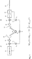
- FIG. 12 shows a block diagram of a known non-synchronous SAR system that includes a transmitter 50 and a receiver 60.
- Transmitter 50 and receiver 60 are formed on different support platforms. Carrier platforms can be airplanes or satellites.
- the transmitter 50 comprises a signal generator 30 to which an internal time reference 34, for example an oscillator, of the transmitter 50 supplies a reference frequency f 0, Tx .
- the internal time reference 34 is also referred to as master clock or master clock.
- the reference frequency f 0, Tx is further supplied to a mixer 37, which is also connected to an output of the signal generator 30.
- the mixer 31 modulates the clock signal f 0, Tx supplied from the internal time reference 34.
- the modulated signal is fed to an amplifier 32 which has its output connected to a transmitting antenna 33.
- the signal antenna 33 emits radar pulses which are reflected by a radar target 43 and received by an antenna 35 of the receiver 60.
- the antenna 35 is connected to an amplifier 36, which supplies the received signal to a mixer 37 for demodulation with a reference frequency f 0, Rx provided by an internal time reference 41.
- a further input of the mixer 37 is connected to the internal time reference 41.
- the internal time reference 41 is connected to a clock generator of the receiver.
- the internal time reference 41 of the receiver 60 also supplies the frequency f 0, Rx in addition to the mixer 37 to an AD converter 39 (ADC).
- ADC AD converter
- the filtered data is supplied to the input of the AD converter 39.
- At the output of the AD converter 39 are thus bistatic data 40 before.
- clock error model is described in more detail in connection with a bistatic SAR response at different time and phase references between the transmitter and the receiver, resulting in the clock phase error to be determined.
- t r the time in the range direction, which is also called “fast” time
- t a the time in azimuth direction, which is also called “slow” time
- f a the azimuth frequency
- f r the range frequency
- f 0 the central frequency (central frequency)
- r 0 the distance (range) to a point-shaped radar target
- ⁇ the wavelength
- c the speed of light
- j - 1 the complex entity.
- the clock phase error in a bistatic SAR system is defined as the difference in the master oscillator phase between the transmitter and the receiver.
- Very good clock stability is an important requirement for a SAR master clock (ie, the internal time references 34, 41 in the Fig. 1 ).
- the clock phase error in a monostatic SAR system is limited to high frequency components of the noise of the master clock phase, since there are small frequencies after demodulation cancel.
- this cancellation or erasure does not occur in bistatic or multistatic SAR systems where other deterministic influences occur in addition to the low and high frequency noise components. This relationship is known in principle from the prior art, so that will not be discussed further in the following.
- t is the absolute time
- t 0 is the start time at which the frequencies of the transmitter and receiver time references begin to drift
- ⁇ f 0, clock ( t ) represents the current frequency offset between the transmitter and receiver time references, the frequency offset being linear terms and Term higher than the first order of the time reference phase error.
- the variable t includes both the fast time components t r and the slow time components t a .
- All useful frequencies for SAR operation may be derived from the respective time reference 34, 41 after respective multiplications or divisions in the mixers 31, 37. These operations, up to a scaling of moments of the variables in the processes involved, do not change the statistical behavior of the various frequencies for radar operation. Therefore, for ⁇ f 0, clock ( t ), it is assumed below that this difference frequency is scaled to the carrier frequency of the radar.
- the bistatic SAR impulse response including the clock phase error must take into account the influence of the clock error on the carrier frequency and the pulse repetition frequency (PRF) of the radar system.
- PRF pulse repetition frequency
- s Tx is the transmitted signal
- r (t a ) corresponds to the bistatic range history
- c is the propagation velocity of the radar signal
- ⁇ is the carrier wavelength
- ⁇ t r, c is a residual range curvature error due to the different time references of transmitter and receiver is inserted.
- the residual curvature error ⁇ t r, c is caused by the difference in effective PRF values of the transmitter and the receiver.
- the residual curvature error can be approximated by ⁇ t r . c t ⁇ ⁇ c ⁇ ⁇ ⁇ clock t 2 ⁇ ,
- Formula (3) represents the distortion in the range direction, assuming that there is a common range reference at the time of starting the echo window.
- the effect of the different time and phase references between transmitter and receiver in the bistatic SAR impulse response is on the one hand that the term ⁇ t r, c changes the range signature of the radar target 43.
- the term ⁇ clock modifies its Doppler signature. This means that unless a correction is achieved, SAR focusing will not be able to accurately reconstruct a reflection map of the illuminated scene.
- FIG. 2 illustrates this effect of missing correction.
- the rectangle labeled A s represents a synchronized SAR image focused in the range-azimuth coordinate system.
- the gray area A n represents the distorted, uncorrected SAR image focused on the same coordinates.
- the individual pixels one of which is exemplary with P in the corrected SAR image, it can be seen that the corresponding pixel P 'has a position and focus error caused by a phase error.
- the focusing error is noticeable in that the pixel P 'occupies a larger area in the distorted image A n .
- the correction of the residual clock phase error can be solved in two different ways, with the corresponding block diagrams in the Fig. 3 and 4 are shown.
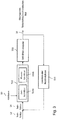
- Fig. 3 only the bistatic SAR data to be corrected is processed. This procedure is referred to as a "self-image approach”.
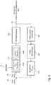
- Fig. 4 In the embodiment shown, the correction is carried out with the aid of a defect-free SAR image, which is regarded as a reference. This approach is called a "reference-image approach".
- Both methods are iterative.
- the estimation of the residual clock phase error enables the focusing of the SAR image to be improved, which also leads to an improvement in the estimate of the residual clock phase error in each iteration step. This means that a better corrected SAR image shows few errors compared to a good SAR image.
- the accuracy of the estimate depends on the accuracy with which phase errors can be measured within the focused SAR image.
- the processing of available calibration information concerning the missing clock phase errors takes place first.
- the initial provision of corresponding "a priori" information or clock phase error is identified by the reference numeral 12.
- SAR data 10 regarding its range and Doppler information is acquired in step S11, S21 corrected.
- the image data 10 can be present as raw data (SAR-Raw) or range-compressed data.
- a bistatic SAR imaging is performed using a known clock phase error 14.
- the clock error 14 may be the "a priori" clock error 12 or a clock error determined during the iteration.
- any known algorithms which have a high accuracy can be used.
- a possible algorithm is described for example in [1]. The principle is that a target on the ground is viewed from different angles by the radar sending and receiving echoes from different positions. The echoes can then be coherently integrated in the same position, which improves the resolution. In SAR processing, the coherent integration is performed efficiently and accurately for the whole picture.
- measurement of the clock phase error takes place within the SAR image generated in step S12, for example using the known autofocus algorithm (step S13).
- the measurement of the residual clock phase error may vary.
- the well-known "Prominent Point Processing” algorithm can be used, which aims at measurements of the phase error, thereby aiming for the presence of bright target points within the image.
- the so-called "map drift" approach uses the second derivative of the phase error, ie two integration steps are required.
- step S23 measurement of a two-dimensional distortion map with respect to a defect-free reference image 18 is performed.
- This approach is to be used advantageously in coherent SAR systems, where an error-free, ie monostatic reference available is.
- a coherent distortion measurement also allows greater accuracy.
- an inversion step (step S24 in FIG Fig. 4 ) carried out.
- the inversion step involves converting the distortion to a residual clock error.
- the residual clock error is in turn supplied to the step S11 or S21 of the correction of the range and / or Doppler information. The exact procedure will be explained in more detail below. Subsequently, one or more further iteration steps take place in the manner described. With each additional iteration, the estimate of the residual clock error becomes smaller until the desired or achievable accuracy is achieved.
- Clock phase errors are not necessarily the only source of residual clock phase errors in bistatic or multistatic SAR systems. However, they are the only original bistatic or multistatic phase error source which relies on already known sources, such as e.g. Residual motion error, atmospheric propagation error, added. The presence of additional phase error sources only alters the type of inversion model that must be considered. The described steps of the algorithm and its applicability, however, remain unchanged.
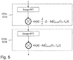
- FIG Fig. 5 An exemplary implementation of the correction of the time reference (sub-steps S11a and S21a of steps S11 and S21, respectively) and the correction of the phase reference (sub-steps S11b and S21b of steps S11 and S21, respectively) is shown in FIG Fig. 5 shown.
- step S12 After correction of the time and phase references, in step S12 (FIG. Fig. 3 ) or step S22 ( Fig. 4 ) generates the bistatic SAR image.
- any image generation algorithms can be used which meet the accuracy requirements of the application.
- the algorithm described in [1] can be used for this purpose.
- the first step is to create a two-dimensional distortion map of the bistatic SAR image generated in step S22 (step S23).
- the distortion may include multiple pixels in the range and azimuth directions, which basically destroys any available coherency between the reference image and the SAR image from step S22.
- the distortion can be measured in this case using a coherent cross-correlation. It should be noted that a method based on estimating the distortion between the two images strongly depends on the observed geometry of the two images. This means that the two images must be close enough to each other so that this distortion can be measured using amplitude information or preferred complex information. A large signal-to-noise ratio (SNR) or coherence between the images is not required, but improves the estimate of co-registration offsets.
- SNR signal-to-noise ratio
- the distortion values expressed as a function of the clock frequency error, can be calculated as follows, where ⁇ t a . clock t r . t a ⁇ ⁇ 2 ⁇ a 2 t r . t a ⁇ ⁇ f 0 clock t r . t a the distortion in azimuth direction and ⁇ t r . clock t r . t a ⁇ ⁇ c ⁇ ⁇ ⁇ clock t r . t a 2 ⁇ the distortion is in range direction.
- a 2 ( t r , t a ) corresponds to the quadratic coefficient of the range history of the target illuminated by the radar pulse at the pixel (t r , t a ).
- this component is usually approximated as a 2 t r . t a ⁇ v e 2 t r . t a 2 ⁇ r 0 t r ,
- Equations (6) and (7) show functional dependencies between the distortion map and the clock phase error.
- the error inversion (step S24) takes into account these dependencies.
- the methods begin again at steps S11 and S21, respectively.
- a timing error for the correction The time and phase reference used here is the timing error determined in the iteration loop. In both cases, the iteration stops if there is no further improvement in the estimate of the residual clock phase error. The result is the synchronized bistatic or multistatic image 16.
- Fig. 6 shows an example of the estimation which is given by the in Fig. 4 shown method has been achieved.
- the bistatic SAR data is taken from a TanDEM-X acquisition. This involves simultaneous acquisition of monostatic SAR data, which can be used as reference data, and measurements from the direct links available for independent verification.
- the dashed line shows the clock phase error estimated by the method described, the measured clock phase error is represented by the solid line. Both lines show good agreement, demonstrating the performance of the proposed approach.
Description
Die Erfindung betrifft ein Verfahren zur Korrektur der Zeit- und Phasenfehler von nicht-synchronen SAR-Daten. Die nicht-synchronen SAR-Daten sind als Bild oder Bilder durch ein bistatisches oder ein multistatisches Radarsystem erfasst und bereitgestellt.The invention relates to a method for correcting the time and phase errors of non-synchronous SAR data. The non-synchronous SAR data is captured and provided as an image or images by a bistatic or multistatic radar system.
SAR (Synthetic Aperture Radar)-Systeme ermöglichen die Fernerkundung der Erdoberfläche für die Erfassung von an der Erdoberfläche reflektierten Radarpulsen, welche von dem SAR-System ausgesendet werden, das sich auf einer Plattform mit konstanter Geschwindigkeit über der Erdoberfläche bewegt. Bei einem solchen System macht man sich die Erkenntnis zunutze, dass aufgrund der bewegten Plattform die gleichen Bereiche der Erde in unterschiedlichen Positionen erfasst werden, wodurch eine Amplituden-Phaseninformation und schließlich ein Radarbild der Erdoberfläche erhalten werden kann.SAR (Synthetic Aperture Radar) systems enable remote sensing of the earth's surface for the detection of surface-reflected radar pulses emitted by the SAR system, which moves on a platform at a constant speed above the Earth's surface. In such a system, one makes use of the knowledge that due to the moving platform the same areas of the earth are detected in different positions, whereby an amplitude phase information and finally a radar image of the earth's surface can be obtained.
Das SAR-System (nachfolgend auch als Satellit bezeichnet) bewegt sich in einer Richtung, welche als Azimut-Richtung bezeichnet wird. Der Satellit, dessen Höhe über der Erdoberfläche bekannt ist, sendet während seiner Bewegung in Azimut-Richtung kontinuierlich Radarpulse über eine Sendeantenne in Richtung zur Erdoberfläche aus. Von jedem ausgesendeten Radarpuls wird das Radarecho erfasst, indem die an der Erdoberfläche reflektierte Radarstrahlung in der sog. Range-Richtung, welche sich senkrecht zur Flugrichtung oder Azimut-Richtung des Satelliten erstreckt, mit einem Empfänger zeitlich abgetastet wird.The SAR system (hereinafter also referred to as satellite) moves in a direction called the azimuth direction. The satellite, whose elevation above the Earth's surface is known, continuously emits radar pulses through its antenna in the direction of the Earth's surface during its movement in the azimuth direction. From each radar pulse emitted, the radar echo is detected by the radar reflected at the earth's surface in the so-called. Range direction, which extends perpendicular to the direction of flight or azimuth direction of the satellite, is scanned in time with a receiver.
Als Folge erhält man eine Vielzahl von Abtastungen, wobei jede Abtastung dem Radarecho eines bestimmten Radarpulses und einer Range-Position entspricht. Die Zuordnung einer Abtastung zu einem Radarpuls wird dabei durch eine Azimut-Position repräsentiert. Der Sender und der Empfänger sind dabei z.B. Bestandteil einer kombinierten Sende-Empfangsantenne, welche im Sendebetrieb den Sender und im Empfangsbetrieb den Empfänger darstellt. In diesem Fall handelt es sich bei dem SAR-System um ein sog. Einzel-Apertur-System, bei dem die Radarechos nur durch einen einzelnen Empfänger, d.h. nicht gleichzeitig durch mehrere Empfänger, erfasst werden.As a result, a plurality of samples are obtained, each sample corresponding to the radar echo of a particular radar pulse and a range position. The assignment of a scan to a radar pulse is represented by an azimuth position. The transmitter and the receiver are e.g. Component of a combined transmit-receive antenna, which represents the transmitter in the transmit mode and the receiver in the receive mode. In this case, the SAR system is a so-called single-aperture system in which the radar echoes are detected only by a single receiver, i. not simultaneously detected by multiple recipients.
Bei der Auswertung werden nur Informationen der Radarstrahlung innerhalb eines von dem ausgesendeten Radarpuls beleuchteten Bodenstreifens (englisch: Swath) erfasst, der eine Breite von mehreren Kilometern, z.B. einige zehn oder hundert Kilometer, aufweisen kann. Die Breite des Bodenstreifens ist unter anderem von der Länge des Zeitfensters abhängig, innerhalb dem die rückgestreuten Radarechos von einem ausgesendeten Impuls durch den Empfänger empfangen werden. Dieses Zeitfenster wird als Echofenster bezeichnet. Die empfangenen Echos werden in ihrer Frequenz konvertiert (d.h. gemischt), demoduliert, digitalisiert und in einer zweidimensionalen Matrix als Rohdaten gespeichert.In the evaluation only information of the radar radiation within a radiated by the emitted radar pulse ground strip (English: Swath) is detected, a width of several kilometers, e.g. a few tens or hundreds of kilometers. Among other things, the width of the ground strip depends on the length of the time window within which the backscattered radar echoes are received by a transmitted pulse by the receiver. This time window is called an echo window. The received echoes are frequency converted (i.e., mixed), demodulated, digitized, and stored in a two-dimensional array as raw data.
Das Prinzip der SAR-Messung beruht nunmehr darauf, dass jeweilige Punkte auf der Erdoberfläche mehrfach aus unterschiedlichen Blickwinkeln aufgrund der Bewegung des Satelliten erfasst werden. Aufgrund des bekannten Doppler-Effekts kommt es bei der Erfassung des Radarechos zu einer Phasenmodulation, die geeignet ausgewertet werden kann, wodurch schließlich für die Punkte der Erdoberfläche, an denen die Radarpulse reflektiert werden, eine Amplituden- und Phaseninformation und somit ein Bildpunkt der Erdoberfläche erhalten wird. Die entsprechende Berechnung von Bildpunkten der Erdoberfläche aus SAR-Daten ist dem Fachmann bekannt und wird deshalb nicht weiter im Detail erläutert. Mit dem SAR-Verfahren wird durch eine Vielzahl von Radarpulsen eines Radarsenders kleiner Apertur eine größere synthetische Apertur entsprechend der Ausdehnung des Radarpulses auf der Erdoberfläche simuliert.The principle of SAR measurement is now based on the fact that respective points on the earth's surface several times from different angles due to the movement of the satellite. Due to the known Doppler effect, a phase modulation occurs during the detection of the radar echo which can be suitably evaluated, as a result of which an amplitude and phase information and thus a pixel of the earth's surface are finally obtained for the points on the earth's surface where the radar pulses are reflected becomes. The corresponding calculation of pixels of the earth's surface from SAR data is known to the person skilled in the art and will therefore not be explained in further detail. With the SAR method, a large number of radar pulses of a small-aperture radar transmitter simulate a larger synthetic aperture corresponding to the extent of the radar pulse on the earth's surface.
Um als Range-Doppler-Radar genutzt werden zu können, bei dem die Range-Bandbreite zur Erzielung einer räumlichen Auflösung in Range-Richtung (sog. across-track-direction) genutzt wird, wird die kohärente Natur eines SAR-Systems genutzt. In ähnlicher Weise führt die Bewegung der Plattform in Flugrichtung zu einer Doppler-Signatur, welche dazu verwendet werden kann, die räumliche Auflösung in Azimut-Richtung (d.h. in der sog. along-track-direction) zu erzielen.In order to be used as a range Doppler radar in which the range bandwidth is used to achieve a spatial resolution in the range direction (so-called across-track direction), the coherent nature of a SAR system is used. Similarly, the movement of the platform in the direction of flight results in a Doppler signature which can be used to achieve spatial resolution in the azimuth direction (i.e., in the so-called along-track direction).
Im Kontext von SAR ist zwischen punktförmigen Rückstreuern und verteilten Rückstreuern zu unterscheiden. Das Radarecho eines Punkt-Streuers ist dominant innerhalb einer Auflösungszelle. Zwei unterschiedliche SAR-Datenerfassungen werden als kohärent betrachtet, wenn die daraus resultierenden SAR-Bilder ein gemeinsames Band des "Szenespektrums" abtasten.In the context of SAR, a distinction should be made between point-shaped backscatterers and distributed backscatterers. The radar echo of a point scatterer is dominant within a resolution cell. Two different SAR data acquisitions are considered to be coherent if the resulting SAR images sample a common band of the "scene spectrum".
Die SAR-Bildgebung basiert auf der Annahme, dass die Reflektivität eines komplexen kohärenten Rückstreuers rekonstruiert werden kann, wenn seine geometrische Position bekannt ist. Aus diesem Grund müssen zwei Bedingungen erfüllt sein, sodass die Rekonstruktion des Radarsignals genau ist: a) die komplexe Reflektivität des Rückstreuers muss so unverzerrt wie möglich aufgenommen werden, und b) seine geometrische Position muss innerhalb der erfassten Daten ermittelbar sein. Die zweite Bedingung ist dabei nur dann erfüllt, wenn der Sender und der Empfänger eine gemeinsame Zeit- und Phasen-Referenz teilen. Eine gemeinsame Zeit- und Phasen-Referenz ist nur dann gegeben, wenn der Sender und der Empfänger grundsätzlich eine gleiche Uhren- oder Zeitreferenz verwenden, was bei sog. monostatischen SAR-Systemen der Fall ist. Demgegenüber arbeiten bistatische und multistatische SAR-Systeme üblicherweise mit unterschiedlichen Zeitreferenzen (Master Clocks) bei Sender und Empfänger. Die Frequenzdifferenz dieser Zeitreferenzen skaliert sich auf die Betriebsfrequenzen der Radarelektronik, wodurch die absolute Zeit- und Phasen-referenz des Systems verloren geht.SAR imaging is based on the assumption that the reflectivity of a complex coherent backscatter can be reconstructed if its geometric position is known. For this reason, two conditions must be satisfied so that the reconstruction of the radar signal is accurate: a) the complex reflectivity of the backscatter must be recorded as undistorted as possible, and b) its geometric position must be determinable within the acquired data. The second condition is only fulfilled if the transmitter and the receiver have a share common time and phase reference. A common time and phase reference is only given if the transmitter and the receiver basically use the same clock or time reference, which is the case with so-called monostatic SAR systems. In contrast, bistatic and multistatic SAR systems usually operate with different time references (master clocks) at transmitter and receiver. The frequency difference of these time references scales to the operating frequencies of the radar electronics, thus losing the absolute time and phase reference of the system.
Der Betrieb eines nicht-synchronen Radarsystems kann auf kooperative oder nichtkooperative Weise erfolgen. Bei einem kooperativen, nicht-synchronen Radarsystem tauschen Sender und Empfänger eine Information über ihre Master-Frequenz aus. In nicht-kooperativen, nicht-synchronen SAR-Systemen arbeiten Sender und Empfänger unabhängig voneinander. Demzufolge findet keine Synchronisation der Zeitreferenz und damit der Referenzfrequenz auf direktem Wege statt. In der folgenden Beschreibung ist somit unter einem nicht-synchronem SAR-System ein nichtkooperatives bistatisches SAR-System oder ein kooperatives bistatisches Radar-System mit erheblichen residuellen Taktphasenfehlern zu verstehen.Operation of a non-synchronous radar system may be cooperative or non-cooperative. In a cooperative, non-synchronous radar system, transmitter and receiver exchange information about their master frequency. In non-cooperative, non-synchronous SAR systems, the sender and receiver work independently of each other. As a result, there is no synchronization of the time reference and thus the reference frequency in a direct way. In the following description, a non-synchronous SAR system is thus understood to mean a noncooperative bistatic SAR system or a cooperative bistatic radar system with significant residual clock phase errors.
Die Kalibrierung eines nicht-synchronen SAR-Systems erfordert eine Anpassung der Position des Echofensters sowie eine Korrektur von Zeit und Phase. Die Anpassung der Position des Echofensters ermöglicht eine erfolgreiche Aufnahme der Radardaten. Die Korrektur von Zeit und Phase ermöglicht die Bildung des erwünschten SAR-Bildes. Während die Anforderungen an die Anpassung der Position des Echofensters gering sind (in der Größenordnung einiger 100 ns) erfordert die Kalibrierung von Zeit und Phase eine wesentlich größere Genauigkeit. Hierzu sind kalibrierte Messungen sowohl von Amplitude und Phase erforderlich. Da viele SAR-Anwendungen kalibrierte Messungen sowohl in Amplitude und Phase benötigen, wäre es wünschenswert, ein Verfahren zu haben, welches die Verarbeitung von nicht-synchronen Daten in automatischer Weise ermöglicht. Der Begriff "automatisch" ist dabei derart zu verstehen, dass lediglich regulär erfasste Radardaten für die Verarbeitung benötigt werden.Calibrating a non-synchronous SAR system requires adjusting the position of the echo window and correcting time and phase. The adjustment of the position of the echo window allows a successful recording of the radar data. The correction of time and phase allows the formation of the desired SAR image. While the requirements for adjusting the position of the echo window are small (on the order of a few 100 ns), the calibration of time and phase requires much greater accuracy. This requires calibrated measurements of both amplitude and phase. Since many SAR applications require calibrated measurements in both amplitude and phase, it would be desirable to have a method that allows the processing of non-synchronous data in an automated manner. The term "automatic" is in this case to understand that only regularly collected radar data are needed for processing.
Die Veröffentlichung
Die Veröffentlichung
Die Veröffentlichung Wen-Qin Wang "
Die Veröffentlichung
Es ist Aufgabe der vorliegenden Erfindung, ein verbessertes Verfahren zur Korrektur der Zeit- und Phasenfehler von nicht-synchronen SAR-Daten anzugeben.It is an object of the present invention to provide an improved method for correcting the time and phase errors of non-synchronous SAR data.
Diese Aufgabe wird gelöst durch ein Verfahren gemäß den Merkmalen des Patentanspruches 1. Vorteilhafte Ausgestaltungen ergeben sich aus den abhängigen Patentansprüchen.This object is achieved by a method according to the features of claim 1. Advantageous embodiments will be apparent from the dependent claims.
Es wird ein Verfahren zur Korrektur der Zeit- und Phasenreferenz von nicht-synchronen SAR-Daten vorgeschlagen, wobei die nicht-synchronen SAR-Daten als Bild oder Bilder durch ein bistatisches oder multistatisches Radarsystem erfasst und bereitgestellt sind. Bei dem Verfahren wird, basierend auf einer, ausschließlichen, Auswertung von Informationen der SAR-Daten ein innerhalb der SAR-Daten vorliegender Residual-Taktphasenfehler geschätzt und korrigiert, wobei die folgenden Schritte ein- oder mehrmals iterativ durchgeführt werden:
- a) Korrektur der Zeit- und Phasenreferenzen der empfangenen SAR-Daten durch die Verarbeitung des geschätzten Residual-Taktphasenfehlers zur Korrektur des geschätzten oder in einem vorhergehenden Iterationsschritt ermittelten Taktphasenfehlers, wodurch eine neue Zeitreferenz erhalten wird;
- b) Erzeugung eines SAR-Bilds aus den korrigierten Radardaten durch die Verarbeitung der neuen Zeitreferenz, wobei eine Rekonstruktion der durch das Radar-System erfassten geometrischen Daten erfolgt;
- c) Schätzung des Residual-Taktphasenfehlers des in Schritt b) erzeugten SAR-Bilds.
- a) correcting the time and phase references of the received SAR data by processing the estimated residual clock phase error to correct the estimated clock phase error detected in a previous iteration step, thereby obtaining a new time reference;
- b) generating an SAR image from the corrected radar data by processing the new time reference, wherein reconstruction of the geometric data acquired by the radar system occurs;
- c) Estimate the residual clock phase error of the SAR image generated in step b).
In Schritt c) wird die Schätzung des Residual-Taktphasenfehlers durch einen Vergleich mit einem Referenz-SAR-Bild, das keinen Taktphasenfehler aufweist, durchgeführt, wobei bezogen auf das Referenz-SAR-Bild eine zweidimensionale Verzerrung des in Schritt b) erzeugten SAR-Bilds ermittelt wird und wobei die Schätzung des Residual-Taktphasenfehlers durch eine Invertierung der ermittelten Verzerrung erfolgt. Die Verzerrung in Azimut-Richtung wird folgender Formel ermittelt: ![]()

![]()
Das Verfahren ermöglicht die Korrektur der Zeit- und Phasenfehler von nicht-synchronen SAR-Daten, ohne besondere Hardwareerfordernisse, wie z.B. einen expliziten Synchronisations-Link, oder die Aufzeichnung eines direkten Radarpulses zu benötigen. Stattdessen kann die Korrektur ausschließlich auf Basis der nicht-synchronen SAR-Daten erfolgen. Insbesondere erlaubt das Verfahren eine Abschätzung des Residual-Taktphasenfehlers beliebiger bistatischer SAR-Daten, wobei diese Abschätzung nur anhand der verfügbaren SAR-Daten erfolgt. Die Korrektur kann auf einfache Weise nach der Aufnahme eines SAR-Bilds erfolgen. Die Synchronisation kann durch ein das SAR-Bild aufnehmendes SAR-System (d.h. "On-Board") oder durch ein von dem SAR-System unterschiedliches Auswertesystem, z.B. "On-Ground", vorgenommen werden.The method enables the correction of the time and phase errors of non-synchronous SAR data without requiring special hardware requirements, such as an explicit sync link, or the need to record a direct radar pulse. Instead, the correction can only be based on the non-synchronous SAR data. In particular, the method allows an estimate of the residual clock phase error of any bistatic SAR data, which estimate is based only on the available SAR data. The correction can be done easily after taking a SAR image. The synchronization can be carried out by a SAR image recording SAR system (ie "on-board") or by a different from the SAR system evaluation system, eg "on-ground".
Das Verfahren ermöglicht die Korrektur mit einer hohen Genauigkeit. Die Rekonstruktion ist effizient und einsetzbar für beliebige Arten von zu überwachenden Szenarien, wie z.B. städtischen oder ländlichen Gebieten. Die Effizienz des Rekonstruktionsverfahrens liegt in der Größenordnung herkömmlicher SAR-Anwendungen.The method allows the correction with a high accuracy. The reconstruction is efficient and usable for any types of scenarios to be monitored, e.g. urban or rural areas. The efficiency of the reconstruction process is on the order of conventional SAR applications.
Das Verfahren kann zur alleinigen Korrektur in nicht-kooperativen SAR-Systemen verwendet werden. Ebenso kann das Verfahren als Backup oder zu Tests in kooperativen SAR-Systemen eingesetzt werden.The method can be used for sole correction in non-cooperative SAR systems. Similarly, the method can be used as a backup or for testing in cooperative SAR systems.
In der Praxis erlaubt es die Abschätzung jeglicher residueller Zeit- und Phasenfehler, so wie ihre Korrektur in Verarbeitungschritten" wodurch geringere Anforderungen an Hardware und/oder Betriebserfordernisse von bistatischen und multistatischen Systemen gestellt werden.In practice, it allows the estimation of any residual time and phase errors, as well as their correction in processing steps, "thus placing lower demands on hardware and / or operating requirements of bistatic and multistatic systems.
Das beschriebene Verfahren wird pixelweise oder blockweise durchgeführt. Ein Block umfasst eine Mehrzahl an Pixeln.The method described is carried out pixel by pixel or block by block. One block comprises a plurality of pixels.
Um die Korrektur der Zeit- und Phaseninformation durchführen zu können, ist zu Beginn des Verfahrens ein initialer Taktphasenfehler erforderlich. Dieser kann auf Basis beliebiger verfügbarer Kalibrierinformationen, falls sie zur Verfügung stehen, geschätzt werden. Kalibrierinformation sind z.B. eine Hardware Messung eines konstanten Frequenzoffsets zwischen Sender und Empfanger bzw. der Phase des direkten Signals u.s.w. Der Taktphasenfehler kann mit null initialisiert werden. Anschließend kann diese initiale Schätzung zu Korrekturzwecken der Zeit- und Phasereferenzen durchgeführt werden. Wahlweise können hierzu SAR-Rohdaten oder komprimierte Range-Daten verwendet werden.In order to be able to carry out the correction of the time and phase information, an initial clock phase error is required at the beginning of the method. This can be estimated based on any available calibration information, if available. Calibration information is e.g. a hardware measurement of a constant frequency offset between transmitter and receiver or the phase of the direct signal u.s.w. The clock phase error can be initialized to zero. Subsequently, this initial estimate can be performed for correction purposes of the time and phase references. Alternatively, raw SAR data or compressed range data may be used.
In Schritt a) kann eine Interpolation in Range-Richtung durchgeführt werden, um eine residuelle Krümmung der Antwort eines betrachteten Radarziels zu kompensieren. Es ist ausreichend, wenn die Interpolation in einer Dimension, nämlich in Range-Richtung, durchgeführt wird.In step a), interpolation in the range direction may be performed to compensate for a residual curvature of the response of a considered radar target. It is sufficient if the interpolation is performed in one dimension, namely in the range direction.
Zur Korrektur der Zeitreferenz können folgende Schritte durchgeführt werden:
- es wird eine 1D-Fast Fourier Transformation (FFT) in Range-Richtung durchgeführt, um die Daten in einen Range-Frequenzbereich umzuwandeln,
- es wird eine Grobverschiebung (Bulk Shift) gemäß folgender Formel ermittelt:

- es wird eine, z.B. lineare oder quadratische, Interpolation geringer Ordnung durchgeführt, und
- es erfolgt eine Umwandlung der Daten in eine zweidimensionale Zeitebene mittels einer Fast Fourier Transformation (FFT) in Range-Richtung.
- a 1D Fast Fourier Transform (FFT) is performed in the range direction to convert the data into a range frequency range
- a coarse shift is determined according to the following formula:
- one, eg linear or quadratic, low-order interpolation is performed, and
- The data is converted into a two-dimensional time plane by means of a Fast Fourier Transformation (FFT) in the range direction.
Zur Korrektur der Phasenfehler von zeitlich älteren Doppler-Informationen kann in Schritt a) eine Phasenkompensation durchgeführt werden. Zur Phasenkompensation der Doppler-Information wird folgendes ermittelt: ![]()
![]()
In Schritt c) kann die Schätzung des Residual-Taktphasenfehlers auf Basis des in dem in Schritt b) erzeugten SAR-Bilds durchgeführt werden. Hierzu kann beispielsweise zur Schätzung ein Autofokus-Algorithmus verarbeitet werden. Hierzu können verschiedene, aus dem Stand der Technik bekannte, Algorithmen verwendet werden. Das Referenz-SAR-Bild kann beispielsweise durch ein monostatisches SAR-System aufgenommen sein. Die Verzerrung kann durch eine inkohärente oder kohärente Kreuzkorrelation ermittelt werden.In step c), the estimate of the residual clock phase error may be made on the basis of the SAR image generated in step b). For this purpose, for example, an autofocus algorithm can be processed for estimation. Various algorithms known from the prior art can be used for this purpose. The reference SAR image may, for example, be recorded by a monostatic SAR system. The distortion can be determined by an incoherent or coherent cross-correlation.
Zusammenfassend wird vorgeschlagen, in einem iterativen Verfahren eine automatische Schätzung und Korrektur eines Taktphasenfehlers in bistatischen oder multistatischen SAR-Daten vorzunehmen. In diesem iterativen Verfahren wird eine Korrektur der SAR-Daten für den verfügbaren Taktphasenfehler durchgeführt. Anschließend erfolgt eine Erzeugung eines (korrigierten) SAR-Bildes. In einer Rückkoppel-oder Feedbackschleife wird in dem neu erzeugten SAR-Bild erneut der verbleibende Taktphasenfehler geschätzt und mit dem neuen Schätzwert eine erneute Schätzung des Taktphasenfehlers und SAR-Bild-Erzeugung vorgenommen, usw.. Das Verfahren endet, wenn sich keine weitere Verbesserung in der Schätzung des Residual-Taktphasenfehlers ergibt. Die Schätzung des verbleibenden Taktphasenfehlers (Residual-Taktphasenfehler) kann auf alleiniger Basis der in dem neuen SAR-Bild enthaltenen Informationen oder durch einen Vergleich mit einem Referenzbild erfolgen.In summary, it is proposed to perform an automatic estimation and correction of a clock phase error in bistatic or multistatic SAR data in an iterative procedure. In this iterative procedure, a correction of the SAR data for the available clock phase error is performed. Subsequently, a generation of a (corrected) SAR image takes place. In a feedback loop, the remaining clock phase error is again estimated in the newly generated SAR image, and with the new estimate, a new estimate of clock phase error and SAR image generation is made, and so on. The method ends when there is no further improvement gives the estimate of the residual clock phase error. The estimation of the remaining clock phase error (residual clock phase error) can be made on the sole basis of the information contained in the new SAR image or by comparison with a reference image.
Die Erfindung wird nachfolgend näher anhand von Ausführungsbeispielen in der Zeichnung erläutert. Es zeigen:
- Fig. 1
- ein Blockdiagramm eines bekannten nicht-synchronen bistatischen SAR-Systems, welches die zur Durchführung des erfindungsgemäßen Verfahrens benötigten SAR-Daten als Bild oder Bilder bereitstellt,
- Fig. 2
- ein Diagramm, das die Effekte eines nicht-synchronen Betriebs in fokussierten SAR-Bildern illustriert,
- Fig. 3
- ein Blockdiagramm eines ersten Ausführungsbeispiels des erfindungsgemäßen Verfahrens,
- Fig. 4
- ein Blockdiagramm eines zweiten Ausführungsbeispiels des erfindungsgemäßen Verfahrens,
- Fig. 5
- eine Darstellung einer beispielhaften Implementierung einer Zeit- und Phasenkorrektur, und
- Fig. 6
- ein Diagramm, das einen gemäß dem erfindungsgemäßen Verfahren geschätzten Taktphasenfehler im Vergleich zu einem gemessen Taktphasenfehler eines korrigierten SAR-Systems zeigt.
- Fig. 1
- 3 is a block diagram of a known non-synchronous bistatic SAR system which provides the SAR data needed to perform the method of the invention as an image or images,
- Fig. 2
- a diagram illustrating the effects of non-synchronous operation in focused SAR images,
- Fig. 3
- a block diagram of a first embodiment of the method according to the invention,
- Fig. 4
- a block diagram of a second embodiment of the method according to the invention,
- Fig. 5
- a representation of an exemplary implementation of a time and phase correction, and
- Fig. 6
- a diagram showing a clock phase error estimated according to the inventive method compared to a measured clock phase error of a corrected SAR system.
Die Antenne 35 ist mit einem Verstärker 36 verbunden, der das empfangene Signal einem Mischer 37 zur Demodulation mit einer von einer internen Zeitreferenz 41 bereitgestellten Referenzfrequenz f0,Rx zuführt. Hierzu ist ein weiterer Eingang des Mischers 37 mit der internen Zeitreferenz 41 verbunden. Die interne Zeitreferenz 41 ist mit einem Taktgenerator des Empfängers verbunden. Die interne Zeitreferenz 41 des Empfängers 60 führt die Frequenz f0,Rx neben dem Mischer 37 auch einem AD-Wandler 39 (ADC) zu. Ausgangsseitig ist der Mischer 37 mit einem Filter 38 (LPF) verbunden. Die gefilterten Daten werden dem Eingang des AD-Wandlers 39 zugeführt. Am Ausgang des AD-Wandlers 39 liegen damit bistatische Daten 40 vor.The
Um eine Kalibrierung der durch den Empfänger 60 aufgezeichneten SAR-Daten vornehmen zu können, ist es erforderlich, den Frequenzunterschied zwischen den Frequenzen der internen Zeitreferenzen 34, 41 des Senders 50 und des Empfängers 60 zu ermitteln. Schematisch werden diese Frequenzen dem Taktsignalkombinator 42 zugeführt, der eine Differenzphase Δϕ gemäß der in
Im nachfolgenden wird das Taktfehlermodell in Verbindung mit einer bistatischen SAR-Antwort bei unterschiedlichen Zeit- und Phasereferenzen zwischen dem Sender und dem Empfänger näher beschrieben, woraus der zu ermittelnde Taktphasenfehler resultiert.In the following, the clock error model is described in more detail in connection with a bistatic SAR response at different time and phase references between the transmitter and the receiver, resulting in the clock phase error to be determined.
In den folgenden Gleichungen repräsentieren:
tr: die Zeit in der Range-Richtung, welche auch als "schnelle" Zeit bezeichnet wird,
ta: die Zeit in Azimut-Richtung, welche auch als "langsame" Zeit bezeichnet wird,
fa: die Azimut-Frequenz, d.h. die Doppler-Frequenz,
fr: die Range-Frequenz,
f0: die zentrale Frequenz (Zentralfrequenz),
r0: die Entfernung (Range) zu einem punktförmigen Radarziel,
λ: die Wellenlänge,
c: die Lichtgeschwindigkeit, und
![]()
t r : the time in the range direction, which is also called "fast" time,
t a : the time in azimuth direction, which is also called "slow" time,
f a : the azimuth frequency, ie the Doppler frequency,
f r : the range frequency,
f 0 : the central frequency (central frequency),
r 0 : the distance (range) to a point-shaped radar target,
λ: the wavelength,
c: the speed of light, and
![]()
Der Taktphasenfehler in einem bistatischen SAR-System ist definiert als die Differenz der Master-Oszillatorphase zwischen dem Sender und dem Empfänger. Eine sehr gute Taktstabilität ist ein wichtiges Erfordernis für eine SAR-Masteruhr (d.h. den internen Zeitreferenzen 34, 41 in der
Der Taktfehler während der Zeit der bistatischen Datenerfassung kann mit nachfolgender Gleichung ausgedrückt werden: ![]()
![]()
Alle nützlichen Frequenzen für den SAR-Betrieb können von der betreffenden Zeitreferenz 34, 41 nach entsprechenden Multiplikationen oder Divisionen in den Mischern 31, 37 abgeleitet werden. Diese Operationen, bis zu einem Skalieren von Momenten der Variablen in den betreffenden Prozessen, verändern nicht das statistische Verhalten der verschiedenen Frequenzen für den Radarbetrieb. Daher wird für Δf 0,clock (t) im Folgenden angenommen, dass diese Differenzfrequenz auf die Trägerfrequenz des Radars skaliert ist.All useful frequencies for SAR operation may be derived from the
Die bistatische SAR-Impulsantwort einschließlich des Taktphasenfehlers muss den Einfluss des Taktfehlers auf die Trägerfrequenz und die Pulswiederholzeit (Puls Repetition Frequency PRF) des Radarsystems in Betracht ziehen. Dies bedeutet, 
![]()
![]()
Formel (3) gibt die Verzerrung in Range-Richtung wieder, wobei davon ausgegangen wird, dass eine gemeinsame Range-Referenz zum Zeitpunkt des Startens des Echofensters gegeben ist. Der Effekt der unterschiedlichen Zeit- und Phasenreferenzen zwischen Sender und Empfänger in der bistatischen SAR-Impulsantwort besteht auf der einen Seite darin, dass der Term Δtr,c die Range-Signatur des Radarziels 43 verändert. Auf der anderen Seite modifiziert der Term Δφclock seine Doppler-Signatur. Dies bedeutet, solange keine Korrektur erreicht ist, ist eine SAR-Fokussierung nicht in der Lage, eine Reflexionskarte der beleuchteten Szenerie genau zu rekonstruieren.Formula (3) represents the distortion in the range direction, assuming that there is a common range reference at the time of starting the echo window. The effect of the different time and phase references between transmitter and receiver in the bistatic SAR impulse response is on the one hand that the term Δt r, c changes the range signature of the
Die Taktphasenfehler verursachen somit Positions- und Phasenfehler in der fokussierten SAR-Zielantwort.
Nachfolgend wird das Vorgehen des erfindungsgemäßen Verfahrens beschrieben, welches auf den vorstehend beschriebenen Erkenntnissen aufbaut.The procedure of the method according to the invention is described below, which is based on the findings described above.
Die Inversion der oben genannten Fehler erleichtert die Möglichkeit des Schätzens des Residual-Taktphasenfehlers innerhalb der nicht-synchronen SAR-Daten. Grundsätzlich kann die Korrektur des Residual-Taktphasenfehlers auf zwei unterschiedliche Arten gelöst werden, wobei die entsprechenden Blockdiagramme in den
Beide Verfahren sind iterativ. Die Abschätzung des Residual-Taktphasenfehlers ermöglicht eine Verbesserung der Fokussierung vom SAR-Bild, was zudem zu einer Verbesserung der Abschätzung des Residual-Taktphasenfehlers in jedem Iterationsschritt führt. Dies bedeutet, ein besser korrigiertes SAR-Bild zeigt wenige Fehler im Vergleich zu einem fehlerfreien SAR-Bild. Die Genauigkeit der Schätzung hängt dabei von der Genauigkeit ab, mit der Phasenfehler innerhalb des fokussierten SAR-Bildes gemessen werden können.Both methods are iterative. The estimation of the residual clock phase error enables the focusing of the SAR image to be improved, which also leads to an improvement in the estimate of the residual clock phase error in each iteration step. This means that a better corrected SAR image shows few errors compared to a good SAR image. The accuracy of the estimate depends on the accuracy with which phase errors can be measured within the focused SAR image.
In beiden Fällen (
Im nächsten Schritt S12, S22 erfolgt eine bistatische SAR-Bilderzeugung unter Verwendung eines bekannten Taktphasenfehlers 14. Der Taktfehler 14 kann der "a priori"-Taktfehler 12 sein oder ein im Rahmen der Iteration ermittelter Taktfehler. Zur Bilderzeugung können beliebige, bekannte Algorithmen, welche eine hohe Genauigkeit aufweisen, verwendet werden. Ein möglicher Algorithmus ist beispielsweise in [1] beschrieben. Das Prinzip ist, dass ein Ziel auf dem Boden von unterschiedlichen Winkeln betrachtet wird, indem das Radar Echos von unterschiedlichen Positionen sendet und empfängt. Die Echos können dann kohärent auf der gleichen Position integriert werden, was die Auflösung verbessert. Bei der SAR-Verarbeitung wird die kohärente Integration effizient und genau für das ganze Bild durchgeführt.In the next step S12, S22 a bistatic SAR imaging is performed using a known
Sobald das SAR-Bild erzeugt ist, wird eine Iterationsschleife durchlaufen. In den folgenden Schritten unterscheiden sich die oben erwähnten beiden Ansätze.Once the SAR image is generated, iterates through an iteration loop. In the following steps, the above-mentioned two approaches differ.
In dem, in
In dem in
Innerhalb der jeweiligen iterativen Schätzschleife, wird ein Inversionsschritt (Schritt S24 in
Taktphasenfehler sind nicht notwendigerweise die einzige Quelle von Residual-Taktphasenfehlern in bistatischen oder multistatischen SAR-Systemen. Sie sind jedoch die einzige originale bistatische bzw. multistatische Phasenfehlerquelle, welche sich auf bereits bekannte Quellen, wie z.B. Residual-Bewegungsfehler, atmosphärische Ausbreitungsfehler, addiert. Das Vorhandensein zusätzlicher Phasenfehlerquellen verändert lediglich die Art des Inversionsmodells, welches in Betracht gezogen werden muss. Die beschriebenen Schritte des Algorithmus und seine Anwendbarkeit bleiben hingegen unverändert.Clock phase errors are not necessarily the only source of residual clock phase errors in bistatic or multistatic SAR systems. However, they are the only original bistatic or multistatic phase error source which relies on already known sources, such as e.g. Residual motion error, atmospheric propagation error, added. The presence of additional phase error sources only alters the type of inversion model that must be considered. The described steps of the algorithm and its applicability, however, remain unchanged.
Unter Bezugnahme auf die
Wie beschrieben, wird davon ausgegangen, dass eine Schätzung des Taktfehlers (vergleiche das Bezugszeichen 14 in ![]()
- i. Eine Korrektur der bistatischen Range, d.h. eine Verschiebung des bistatischen Echos durch Δtr,c (tr ,ta ). Eine akkurate Implementierung dieser Verschiebung erfordert eine eindimensionale Interpolation. Eine zulässige Vereinfachung für Fehler, in denen die Variation dieses Wertes innerhalb des Echofensters klein ist im Vergleich zum Inversen der übertragenen Bandbreite, ist möglich. In diesen Fehlern kann die Interpolation ersetzt werden durch eine Hauptverschiebung (Bulk Shift) mit dem Mittelwert innerhalb des Echofensters

- ii. eine Phasenkompensation der Form


- i. A correction of the bistatic range, ie a shift of the bistatic echo by Δt r, c ( t r , t a ) . An accurate implementation of this shift requires one-dimensional interpolation. An allowable simplification for errors in which the variation of this value within the echo window is small compared to the inverse of the transmitted bandwidth is possible. In these errors, the interpolation can be replaced by a main shift (bulk shift) with the mean value within the echo window
- ii. a phase compensation of the shape
Eine beispielhafte Implementierung der Korrektur der Zeitreferenz (Teilschritt S11a bzw. S21a der Schritte S11 bzw. S21) und der Korrektur der Phasenreferenz (Teilschritt S11b bzw. S21b der Schritte S11 bzw. S21) ist in
Nach der Korrektur der Zeit- und Phasenreferenzen wird in Schritt S12 (
Nach der SAR-Bilderzeugung unterscheiden sich die Vorgehensweisen von
Zunächst wird auf das Vorgehen in
Bei der in
Der Vorteil dieses Verfahrens, verglichen mit dem in Verbindung mit
Die Verzerrungswerte, ausgedrückt als Funktion des Taktfrequenzfehlers, können wie folgt berechnet werden, wobei ![]()
![]()

![]()
![]()
Dabei ist ve die effektive Geschwindigkeit.Where v e is the effective speed.
Die Gleichungen (6) und (7) zeigen funktionale Abhängigkeiten zwischen der Verzerrungskarte und dem Taktphasenfehler. Die Fehlerinvertierung (Schritt S24) berücksichtigt diese Abhängigkeiten.Equations (6) and (7) show functional dependencies between the distortion map and the clock phase error. The error inversion (step S24) takes into account these dependencies.
Sobald die Iteration des Residual-Taktphasenfehlers ermittelt wurde, beginnen die Verfahren bei den Schritten S11 bzw. S21 von neuem. Als Taktfehler für die Korrektur der Zeit- und Phasenreferenz wird dabei der in der Iterationsschleife ermittelte Taktfehler verwendet. In beiden Fällen stoppt die Iteration, wenn sich keine weitere Verbesserung in der Schätzung des Residual-Taktphasenfehlers ergibt. Das Ergebnis ist das synchronisierte bistatische oder multistatische Bild 16.Once the iteration of the residual clock phase error has been detected, the methods begin again at steps S11 and S21, respectively. As a timing error for the correction The time and phase reference used here is the timing error determined in the iteration loop. In both cases, the iteration stops if there is no further improvement in the estimate of the residual clock phase error. The result is the synchronized bistatic or
In einem herkömmlichen System, wie z.B. TanDEM-X ist es üblich, dass die Verzerrung aufgrund eines Taktphasenfehlers mit einer größeren Genauigkeit in Azimut-Richtung gemessen werden können als in Range-Richtung. In diesem Fall kann die Inversion lediglich auf die Azimut-Verzerrungsschätzung ![]()
![]()
![]()
![]()
![]()
![]()
- 1010
- Bilddatenimage data
- 1212
- A priori PhasenfehlerA priori phase error
- 1414
- Phasenfehlerphase error
- 1616
- korrigiertes Bildcorrected picture
- 3030
- Signalgeneratorsignal generator
- 3131
- Mischermixer
- 3232
- Verstärkeramplifier
- 3333
- Sendeantennetransmitting antenna
- 3434
- interne Zeitreferenzinternal time reference
- 3535
- Empfangsantennereceiving antenna
- 3636
- Verstärkeramplifier
- 3737
- Signalkombinationsignal combination
- 3838
- Filterfilter
- 3939
- AD-WandlerADC
- 4040
- bistatische Datenbistatic data
- 4141
- interne Zeitreferenz des Empfängersinternal time reference of the recipient
- 4242
- TaktsignalkombinationClock combination
- 4343
- Radarzielradar target
- As A s
- Bildbereich eines korrigierten SAR-BildsImage area of a corrected SAR image
- An A n
- Bildbereich eines nicht korrigierten SAR-BildsImage area of an uncorrected SAR image
- S11S11
- Korrekturschrittcorrection step
- S11aS11a
- Zeitkorrekturtime correction
- S11bS11b
- Phasenkorrekturphase correction
- S12S12
- BilderzeugungsschrittImaging step
- S13S13
- ResidualphasenermittlungsschrittResidualphasenermittlungsschritt
- S21S21
- Korrekturschrittcorrection step
- S21aS21a
- Zeitkorrekturtime correction
- S21bS21b
- Phasenkorrekturphase correction
- S22S22
- BilderzeugungsschrittImaging step
- S23S23
- Verzerrungsschätzungdistortion estimate
- S24S24
- FehlerinvertierungFehlerinvertierung
- S25S25
- Integrationsschrittintegration step
-
[1]
M. Rodriguez-Cassola, P. Prats, G. Krieger, und A. Moreira, "Efficient timedomain image formation with precise topography accommodation for general bistatic SAR configurations", IEEE Transactions on Aerospace and Electronic Systems, vol. 24, no. 3, pp. 218-223, Oct. 2011 M. Rodriguez-Cassola, P. Prats, G. Krieger, and A. Moreira, "Efficient Time Domain Formation with Precise Topography for General Bistatic SAR configurations", IEEE Transactions on Aerospace and Electronic Systems, vol. 24, no. 3, pp. 218-223, Oct. 2011
Claims (8)
- A method for estimating and correcting the time and phase references of nonsynchronous SAR data, the nonsynchronous SAR data being captured and provided as an image or images by a bistatic or multistatic radar system, wherein based on an exclusive analysis of information of the SAR data, a residual clock-phase error within the SAR data is estimated and corrected, wherein the following steps are performed iteratively once or several times:a) Correction of the time and phase references (S11; S21) of the received SAR data by processing the estimated residual clock-phase error for correcting the estimated clock phase error or that has been determined in a previous iterative step, whereby a new time reference is obtained;b) Generation of an SAR image (S12; S22) by processing the new time reference, a reconstruction of the geometric data captured by the radar system taking place in the process;c) Estimation of the residual clock-phase error (S13; S23, S24, S25) of the SAR image generated at step b);characterized in that- in step c), the estimation of the residual clock-phase error is performed by way of a comparison with a reference SAR image that does not have a clock-phase error, a two-dimensional distortion of the SAR image generated at step b) being determined with regard to the reference SAR image and the estimation of the residual clock-phase error being carried out by inverting the determined distortion;- the distortion in the azimuth direction is determined in accordance with the following formula:wherein a2(tr, ta) corresponds to the quadratic coefficient of the range history of the particular pixel (tr, ta) and Δf 0,clock (tr ,ta ) is the current frequency offset; and
 - the distortion in the range direction is determined in accordance with the following formula:
- The method according to claim 1, wherein in step a) an interpolation is performed in the range direction in order to compensate for the residual curvature of the response of a particular target.
- The method according to claim 1, wherein in order to interpolate the range information- a bulk shift is determined in accordance with the following formula:
 - a linear or quadratic interpolation is carried out, and- a conversion of the data into a two-dimensional time level is performed by means of a fast Fourier transform in the range direction.
 - The method according to one of the afore-mentioned claims, wherein in step a) a phase compensation is performed for correcting the phase reference.
- The method according to claim 4, wherein the following is determined for phase compensation of the Doppler information:

- The method according to one of the afore-mentioned claims, wherein an auto-focus algorithm is processed for the estimation.
- The method according to one of the afore-mentioned claims, wherein the reference SAR image is captured by a mono static SAR system.
- The method according to one of the afore-mentioned claims, wherein the distortion is determined by an incoherent or coherent cross-correlation.
Applications Claiming Priority (1)
| Application Number | Priority Date | Filing Date | Title |
|---|---|---|---|
| DE102013214676.0A DE102013214676A1 (en) | 2013-07-26 | 2013-07-26 | Method for correcting the time and phase references of non-synchronous SAR data |
Publications (2)
| Publication Number | Publication Date |
|---|---|
| EP2843439A1 EP2843439A1 (en) | 2015-03-04 |
| EP2843439B1 true EP2843439B1 (en) | 2018-03-14 |
Family
ID=51212783
Family Applications (1)
| Application Number | Title | Priority Date | Filing Date |
|---|---|---|---|
| EP14178361.3A Active EP2843439B1 (en) | 2013-07-26 | 2014-07-24 | Method for correcting the time and phase references of asynchronous SAR data |
Country Status (2)
| Country | Link |
|---|---|
| EP (1) | EP2843439B1 (en) |
| DE (1) | DE102013214676A1 (en) |
Families Citing this family (15)
| Publication number | Priority date | Publication date | Assignee | Title |
|---|---|---|---|---|
| CN104898120A (en) * | 2015-06-12 | 2015-09-09 | 西安电子科技大学 | Double-base foresight high-mobility platform SAR imaging method based on echo simulation |
| CN110389323B (en) * | 2018-04-18 | 2021-06-11 | 北京航空航天大学 | Multichannel spaceborne SAR phase equalization method and device, storage medium and equipment |
| CN109765556A (en) * | 2018-12-29 | 2019-05-17 | 成都航天科工微电子系统研究院有限公司 | A kind of bearing calibration of Bistatic SAR fast geometric and device based on series inverting |
| CN110187347B (en) * | 2019-06-26 | 2021-01-12 | 电子科技大学 | Large-width imaging method of geosynchronous orbit satellite-machine bistatic synthetic aperture radar |
| CN110967693B (en) * | 2019-11-06 | 2023-07-07 | 西安电子科技大学 | Robust and efficient fast decomposition projection automatic focusing method and system |
| CN111175747B (en) * | 2019-11-28 | 2023-05-05 | 西安电子科技大学 | Phase error estimation method based on multichannel complex image space |
| CN112285662B (en) * | 2020-09-30 | 2023-08-15 | 北京空间飞行器总体设计部 | SAR load antenna radiation characteristic test method |
| CN112285701A (en) * | 2020-10-22 | 2021-01-29 | 香港中文大学(深圳) | Error correction method for three-dimensional networking radar system |
| CN112946589B (en) * | 2021-02-01 | 2022-09-06 | 上海交通大学 | Phase self-calibration method for motion measurement of asynchronous FMCW radar system |
| CN112904341B (en) * | 2021-03-03 | 2023-03-24 | 北京无线电测量研究所 | Doppler imaging method and system with space variation along with distance for SAR |
| CN113221062B (en) * | 2021-04-07 | 2023-03-28 | 北京理工大学 | High-frequency motion error compensation method of small unmanned aerial vehicle-mounted BiSAR system |
| CN113406627B (en) * | 2021-05-12 | 2023-05-16 | 北京理工大学 | Two-step channel error estimation and compensation method for distributed multi-channel SAR |
| CN115575956B (en) * | 2022-12-07 | 2023-03-10 | 中国科学院空天信息创新研究院 | Detection and compensation method for phase synchronization interference signal of formation SAR satellite |
| CN116380148B (en) * | 2023-04-06 | 2023-11-10 | 中国人民解放军93209部队 | Two-stage space-time error calibration method and device for multi-sensor target tracking system |
| CN117092649B (en) * | 2023-10-11 | 2023-12-26 | 中国科学院空天信息创新研究院 | Moon orbit synthetic aperture radar imaging orbit error compensation method |
Family Cites Families (1)
| Publication number | Priority date | Publication date | Assignee | Title |
|---|---|---|---|---|
| US6181270B1 (en) * | 1999-02-23 | 2001-01-30 | Veridian Erim International, Inc. | Reference-based autofocusing method for IFSAR and other applications |
-
2013
- 2013-07-26 DE DE102013214676.0A patent/DE102013214676A1/en not_active Withdrawn
-
2014
- 2014-07-24 EP EP14178361.3A patent/EP2843439B1/en active Active
Non-Patent Citations (1)
| Title |
|---|
| None * |
Also Published As
| Publication number | Publication date |
|---|---|
| DE102013214676A1 (en) | 2015-01-29 |
| EP2843439A1 (en) | 2015-03-04 |
Similar Documents
| Publication | Publication Date | Title |
|---|---|---|
| EP2843439B1 (en) | Method for correcting the time and phase references of asynchronous SAR data | |
| EP2875384B1 (en) | Method for processing high-resolution spaceborne spotlight sar raw data | |
| De Macedo et al. | An autofocus approach for residual motion errors with application to airborne repeat-pass SAR interferometry | |
| EP3364212A1 (en) | A method and an apparatus for computer-assisted processing of sar raw data | |
| DE102015120733B4 (en) | Radar device with phase noise estimation | |
| EP2998763B1 (en) | Phase calibration of a stepped-chirp signal for a synthetic aperture radar | |
| DE102009000468B4 (en) | Radar methods and systems with ramp sequences | |
| DE102015100804B4 (en) | Radar device with noise reduction | |
| US11209540B2 (en) | SAR imaging method for interferometric analyses | |
| EP3012658B1 (en) | Method and device for implementing sar imaging | |
| EP3803454B1 (en) | Synthetic-aperture radar method and synthetic-aperture radar device | |
| EP3588134A1 (en) | Method in a radar system, radar system or device in a radar system | |
| WO2006122748A1 (en) | Phase ambiguity resolution method for a satellite-based positioning system | |
| EP1637902A1 (en) | Method and device for interferometric radar measurement | |
| WO2008119455A1 (en) | Method for examining an ice region or dry region using radar echo sounding | |
| WO2021047844A1 (en) | Radar method and radar system | |
| DE102017110404A1 (en) | Method and device for compensation of disturbing influences | |
| DE69630816T2 (en) | DOPPLER RADAR ALTIMETER WITH COMPENSATED DELAY | |
| CN113484859A (en) | Two-dimensional super-resolution radar imaging method based on fusion technology | |
| Dong et al. | A Novel Geosynchronous Spaceborne-Airborne Bistatic Multichannel Sar For Ground Moving Targets Indication | |
| EP2829892B1 (en) | Method for the computer-assisted processing of SAR data | |
| DE102004045273B4 (en) | Image generation method for a synthetic aperture radar | |
| Sommer et al. | Image reconstruction without an inertial navigation system using backprojection autofocus for synthetic aperture radar | |
| Zhang et al. | Influence of Time Synchronization Error on Bistatic Geo SAR Imaging | |
| Yu et al. | A new imaging algorithm for highly squinted azimuth multi-channel TOPSAR |
Legal Events
| Date | Code | Title | Description |
|---|---|---|---|
| 17P | Request for examination filed |
Effective date: 20140724 |
|
| AK | Designated contracting states |
Kind code of ref document: A1 Designated state(s): AL AT BE BG CH CY CZ DE DK EE ES FI FR GB GR HR HU IE IS IT LI LT LU LV MC MK MT NL NO PL PT RO RS SE SI SK SM TR |
|
| AX | Request for extension of the european patent |
Extension state: BA ME |
|
| PUAI | Public reference made under article 153(3) epc to a published international application that has entered the european phase |
Free format text: ORIGINAL CODE: 0009012 |
|
| R17P | Request for examination filed (corrected) |
Effective date: 20150821 |
|
| RBV | Designated contracting states (corrected) |
Designated state(s): AL AT BE BG CH CY CZ DE DK EE ES FI FR GB GR HR HU IE IS IT LI LT LU LV MC MK MT NL NO PL PT RO RS SE SI SK SM TR |
|
| GRAP | Despatch of communication of intention to grant a patent |
Free format text: ORIGINAL CODE: EPIDOSNIGR1 |
|
| STAA | Information on the status of an ep patent application or granted ep patent |
Free format text: STATUS: GRANT OF PATENT IS INTENDED |
|
| RIC1 | Information provided on ipc code assigned before grant |
Ipc: G01S 13/00 20060101ALI20170913BHEP Ipc: G01S 13/90 20060101AFI20170913BHEP |
|
| INTG | Intention to grant announced |
Effective date: 20171010 |
|
| GRAS | Grant fee paid |
Free format text: ORIGINAL CODE: EPIDOSNIGR3 |
|
| GRAA | (expected) grant |
Free format text: ORIGINAL CODE: 0009210 |
|
| STAA | Information on the status of an ep patent application or granted ep patent |
Free format text: STATUS: THE PATENT HAS BEEN GRANTED |
|
| AK | Designated contracting states |
Kind code of ref document: B1 Designated state(s): AL AT BE BG CH CY CZ DE DK EE ES FI FR GB GR HR HU IE IS IT LI LT LU LV MC MK MT NL NO PL PT RO RS SE SI SK SM TR |
|
| REG | Reference to a national code |
Ref country code: GB Ref legal event code: FG4D Free format text: NOT ENGLISH |
|
| REG | Reference to a national code |
Ref country code: CH Ref legal event code: EP Ref country code: AT Ref legal event code: REF Ref document number: 979424 Country of ref document: AT Kind code of ref document: T Effective date: 20180315 |
|
| REG | Reference to a national code |
Ref country code: IE Ref legal event code: FG4D Free format text: LANGUAGE OF EP DOCUMENT: GERMAN |
|
| REG | Reference to a national code |
Ref country code: DE Ref legal event code: R096 Ref document number: 502014007608 Country of ref document: DE |
|
| REG | Reference to a national code |
Ref country code: FR Ref legal event code: PLFP Year of fee payment: 5 |
|
| REG | Reference to a national code |
Ref country code: NL Ref legal event code: MP Effective date: 20180314 |
|
| REG | Reference to a national code |
Ref country code: LT Ref legal event code: MG4D |
|
| PG25 | Lapsed in a contracting state [announced via postgrant information from national office to epo] |
Ref country code: FI Free format text: LAPSE BECAUSE OF FAILURE TO SUBMIT A TRANSLATION OF THE DESCRIPTION OR TO PAY THE FEE WITHIN THE PRESCRIBED TIME-LIMIT Effective date: 20180314 Ref country code: NO Free format text: LAPSE BECAUSE OF FAILURE TO SUBMIT A TRANSLATION OF THE DESCRIPTION OR TO PAY THE FEE WITHIN THE PRESCRIBED TIME-LIMIT Effective date: 20180614 Ref country code: HR Free format text: LAPSE BECAUSE OF FAILURE TO SUBMIT A TRANSLATION OF THE DESCRIPTION OR TO PAY THE FEE WITHIN THE PRESCRIBED TIME-LIMIT Effective date: 20180314 Ref country code: LT Free format text: LAPSE BECAUSE OF FAILURE TO SUBMIT A TRANSLATION OF THE DESCRIPTION OR TO PAY THE FEE WITHIN THE PRESCRIBED TIME-LIMIT Effective date: 20180314 Ref country code: CY Free format text: LAPSE BECAUSE OF FAILURE TO SUBMIT A TRANSLATION OF THE DESCRIPTION OR TO PAY THE FEE WITHIN THE PRESCRIBED TIME-LIMIT Effective date: 20180314 |
|
| PG25 | Lapsed in a contracting state [announced via postgrant information from national office to epo] |
Ref country code: BG Free format text: LAPSE BECAUSE OF FAILURE TO SUBMIT A TRANSLATION OF THE DESCRIPTION OR TO PAY THE FEE WITHIN THE PRESCRIBED TIME-LIMIT Effective date: 20180614 Ref country code: GR Free format text: LAPSE BECAUSE OF FAILURE TO SUBMIT A TRANSLATION OF THE DESCRIPTION OR TO PAY THE FEE WITHIN THE PRESCRIBED TIME-LIMIT Effective date: 20180615 Ref country code: LV Free format text: LAPSE BECAUSE OF FAILURE TO SUBMIT A TRANSLATION OF THE DESCRIPTION OR TO PAY THE FEE WITHIN THE PRESCRIBED TIME-LIMIT Effective date: 20180314 Ref country code: SE Free format text: LAPSE BECAUSE OF FAILURE TO SUBMIT A TRANSLATION OF THE DESCRIPTION OR TO PAY THE FEE WITHIN THE PRESCRIBED TIME-LIMIT Effective date: 20180314 Ref country code: RS Free format text: LAPSE BECAUSE OF FAILURE TO SUBMIT A TRANSLATION OF THE DESCRIPTION OR TO PAY THE FEE WITHIN THE PRESCRIBED TIME-LIMIT Effective date: 20180314 |
|
| PG25 | Lapsed in a contracting state [announced via postgrant information from national office to epo] |
Ref country code: MT Free format text: LAPSE BECAUSE OF FAILURE TO SUBMIT A TRANSLATION OF THE DESCRIPTION OR TO PAY THE FEE WITHIN THE PRESCRIBED TIME-LIMIT Effective date: 20180314 |
|
| PG25 | Lapsed in a contracting state [announced via postgrant information from national office to epo] |
Ref country code: EE Free format text: LAPSE BECAUSE OF FAILURE TO SUBMIT A TRANSLATION OF THE DESCRIPTION OR TO PAY THE FEE WITHIN THE PRESCRIBED TIME-LIMIT Effective date: 20180314 Ref country code: AL Free format text: LAPSE BECAUSE OF FAILURE TO SUBMIT A TRANSLATION OF THE DESCRIPTION OR TO PAY THE FEE WITHIN THE PRESCRIBED TIME-LIMIT Effective date: 20180314 Ref country code: NL Free format text: LAPSE BECAUSE OF FAILURE TO SUBMIT A TRANSLATION OF THE DESCRIPTION OR TO PAY THE FEE WITHIN THE PRESCRIBED TIME-LIMIT Effective date: 20180314 Ref country code: PL Free format text: LAPSE BECAUSE OF FAILURE TO SUBMIT A TRANSLATION OF THE DESCRIPTION OR TO PAY THE FEE WITHIN THE PRESCRIBED TIME-LIMIT Effective date: 20180314 Ref country code: RO Free format text: LAPSE BECAUSE OF FAILURE TO SUBMIT A TRANSLATION OF THE DESCRIPTION OR TO PAY THE FEE WITHIN THE PRESCRIBED TIME-LIMIT Effective date: 20180314 Ref country code: ES Free format text: LAPSE BECAUSE OF FAILURE TO SUBMIT A TRANSLATION OF THE DESCRIPTION OR TO PAY THE FEE WITHIN THE PRESCRIBED TIME-LIMIT Effective date: 20180314 |
|
| PG25 | Lapsed in a contracting state [announced via postgrant information from national office to epo] |
Ref country code: CZ Free format text: LAPSE BECAUSE OF FAILURE TO SUBMIT A TRANSLATION OF THE DESCRIPTION OR TO PAY THE FEE WITHIN THE PRESCRIBED TIME-LIMIT Effective date: 20180314 Ref country code: SK Free format text: LAPSE BECAUSE OF FAILURE TO SUBMIT A TRANSLATION OF THE DESCRIPTION OR TO PAY THE FEE WITHIN THE PRESCRIBED TIME-LIMIT Effective date: 20180314 Ref country code: SM Free format text: LAPSE BECAUSE OF FAILURE TO SUBMIT A TRANSLATION OF THE DESCRIPTION OR TO PAY THE FEE WITHIN THE PRESCRIBED TIME-LIMIT Effective date: 20180314 |
|
| REG | Reference to a national code |
Ref country code: DE Ref legal event code: R097 Ref document number: 502014007608 Country of ref document: DE |
|
| PG25 | Lapsed in a contracting state [announced via postgrant information from national office to epo] |
Ref country code: PT Free format text: LAPSE BECAUSE OF FAILURE TO SUBMIT A TRANSLATION OF THE DESCRIPTION OR TO PAY THE FEE WITHIN THE PRESCRIBED TIME-LIMIT Effective date: 20180716 |
|
| PLBE | No opposition filed within time limit |
Free format text: ORIGINAL CODE: 0009261 |
|
| STAA | Information on the status of an ep patent application or granted ep patent |
Free format text: STATUS: NO OPPOSITION FILED WITHIN TIME LIMIT |
|
| PG25 | Lapsed in a contracting state [announced via postgrant information from national office to epo] |
Ref country code: DK Free format text: LAPSE BECAUSE OF FAILURE TO SUBMIT A TRANSLATION OF THE DESCRIPTION OR TO PAY THE FEE WITHIN THE PRESCRIBED TIME-LIMIT Effective date: 20180314 |
|
| 26N | No opposition filed |
Effective date: 20181217 |
|
| PG25 | Lapsed in a contracting state [announced via postgrant information from national office to epo] |
Ref country code: SI Free format text: LAPSE BECAUSE OF FAILURE TO SUBMIT A TRANSLATION OF THE DESCRIPTION OR TO PAY THE FEE WITHIN THE PRESCRIBED TIME-LIMIT Effective date: 20180314 |
|
| REG | Reference to a national code |
Ref country code: CH Ref legal event code: PL |
|
| PG25 | Lapsed in a contracting state [announced via postgrant information from national office to epo] |
Ref country code: LU Free format text: LAPSE BECAUSE OF NON-PAYMENT OF DUE FEES Effective date: 20180724 Ref country code: MC Free format text: LAPSE BECAUSE OF FAILURE TO SUBMIT A TRANSLATION OF THE DESCRIPTION OR TO PAY THE FEE WITHIN THE PRESCRIBED TIME-LIMIT Effective date: 20180314 |
|
| REG | Reference to a national code |
Ref country code: IE Ref legal event code: MM4A |
|
| PG25 | Lapsed in a contracting state [announced via postgrant information from national office to epo] |
Ref country code: CH Free format text: LAPSE BECAUSE OF NON-PAYMENT OF DUE FEES Effective date: 20180731 Ref country code: LI Free format text: LAPSE BECAUSE OF NON-PAYMENT OF DUE FEES Effective date: 20180731 Ref country code: IE Free format text: LAPSE BECAUSE OF NON-PAYMENT OF DUE FEES Effective date: 20180724 |
|
| PG25 | Lapsed in a contracting state [announced via postgrant information from national office to epo] |
Ref country code: TR Free format text: LAPSE BECAUSE OF FAILURE TO SUBMIT A TRANSLATION OF THE DESCRIPTION OR TO PAY THE FEE WITHIN THE PRESCRIBED TIME-LIMIT Effective date: 20180314 |
|
| PG25 | Lapsed in a contracting state [announced via postgrant information from national office to epo] |
Ref country code: HU Free format text: LAPSE BECAUSE OF FAILURE TO SUBMIT A TRANSLATION OF THE DESCRIPTION OR TO PAY THE FEE WITHIN THE PRESCRIBED TIME-LIMIT; INVALID AB INITIO Effective date: 20140724 |
|
| PG25 | Lapsed in a contracting state [announced via postgrant information from national office to epo] |
Ref country code: MK Free format text: LAPSE BECAUSE OF NON-PAYMENT OF DUE FEES Effective date: 20180314 |
|
| PG25 | Lapsed in a contracting state [announced via postgrant information from national office to epo] |
Ref country code: IS Free format text: LAPSE BECAUSE OF FAILURE TO SUBMIT A TRANSLATION OF THE DESCRIPTION OR TO PAY THE FEE WITHIN THE PRESCRIBED TIME-LIMIT Effective date: 20180714 |
|
| REG | Reference to a national code |
Ref country code: AT Ref legal event code: MM01 Ref document number: 979424 Country of ref document: AT Kind code of ref document: T Effective date: 20190724 |
|
| PG25 | Lapsed in a contracting state [announced via postgrant information from national office to epo] |
Ref country code: AT Free format text: LAPSE BECAUSE OF NON-PAYMENT OF DUE FEES Effective date: 20190724 |
|
| PGFP | Annual fee paid to national office [announced via postgrant information from national office to epo] |
Ref country code: FR Payment date: 20230616 Year of fee payment: 10 |
|
| PGFP | Annual fee paid to national office [announced via postgrant information from national office to epo] |
Ref country code: BE Payment date: 20230616 Year of fee payment: 10 |
|
| PGFP | Annual fee paid to national office [announced via postgrant information from national office to epo] |
Ref country code: IT Payment date: 20230712 Year of fee payment: 10 Ref country code: GB Payment date: 20230614 Year of fee payment: 10 |
|
| PGFP | Annual fee paid to national office [announced via postgrant information from national office to epo] |
Ref country code: DE Payment date: 20230614 Year of fee payment: 10 |