EP2843346B1 - Fin-tube heat exchanger and method of manufacturing the same - Google Patents
Fin-tube heat exchanger and method of manufacturing the same Download PDFInfo
- Publication number
- EP2843346B1 EP2843346B1 EP13781866.2A EP13781866A EP2843346B1 EP 2843346 B1 EP2843346 B1 EP 2843346B1 EP 13781866 A EP13781866 A EP 13781866A EP 2843346 B1 EP2843346 B1 EP 2843346B1
- Authority
- EP
- European Patent Office
- Prior art keywords
- fin
- portions
- tube
- heat exchanger
- fins
- Prior art date
- Legal status (The legal status is an assumption and is not a legal conclusion. Google has not performed a legal analysis and makes no representation as to the accuracy of the status listed.)
- Active
Links
Images





Classifications
-
- F—MECHANICAL ENGINEERING; LIGHTING; HEATING; WEAPONS; BLASTING
- F28—HEAT EXCHANGE IN GENERAL
- F28F—DETAILS OF HEAT-EXCHANGE AND HEAT-TRANSFER APPARATUS, OF GENERAL APPLICATION
- F28F17/00—Removing ice or water from heat-exchange apparatus
- F28F17/005—Means for draining condensates from heat exchangers, e.g. from evaporators
-
- F—MECHANICAL ENGINEERING; LIGHTING; HEATING; WEAPONS; BLASTING
- F28—HEAT EXCHANGE IN GENERAL
- F28D—HEAT-EXCHANGE APPARATUS, NOT PROVIDED FOR IN ANOTHER SUBCLASS, IN WHICH THE HEAT-EXCHANGE MEDIA DO NOT COME INTO DIRECT CONTACT
- F28D1/00—Heat-exchange apparatus having stationary conduit assemblies for one heat-exchange medium only, the media being in contact with different sides of the conduit wall, in which the other heat-exchange medium is a large body of fluid, e.g. domestic or motor car radiators
- F28D1/02—Heat-exchange apparatus having stationary conduit assemblies for one heat-exchange medium only, the media being in contact with different sides of the conduit wall, in which the other heat-exchange medium is a large body of fluid, e.g. domestic or motor car radiators with heat-exchange conduits immersed in the body of fluid
- F28D1/04—Heat-exchange apparatus having stationary conduit assemblies for one heat-exchange medium only, the media being in contact with different sides of the conduit wall, in which the other heat-exchange medium is a large body of fluid, e.g. domestic or motor car radiators with heat-exchange conduits immersed in the body of fluid with tubular conduits
- F28D1/047—Heat-exchange apparatus having stationary conduit assemblies for one heat-exchange medium only, the media being in contact with different sides of the conduit wall, in which the other heat-exchange medium is a large body of fluid, e.g. domestic or motor car radiators with heat-exchange conduits immersed in the body of fluid with tubular conduits the conduits being bent, e.g. in a serpentine or zig-zag
-
- F—MECHANICAL ENGINEERING; LIGHTING; HEATING; WEAPONS; BLASTING
- F28—HEAT EXCHANGE IN GENERAL
- F28F—DETAILS OF HEAT-EXCHANGE AND HEAT-TRANSFER APPARATUS, OF GENERAL APPLICATION
- F28F1/00—Tubular elements; Assemblies of tubular elements
- F28F1/10—Tubular elements and assemblies thereof with means for increasing heat-transfer area, e.g. with fins, with projections, with recesses
- F28F1/12—Tubular elements and assemblies thereof with means for increasing heat-transfer area, e.g. with fins, with projections, with recesses the means being only outside the tubular element
- F28F1/24—Tubular elements and assemblies thereof with means for increasing heat-transfer area, e.g. with fins, with projections, with recesses the means being only outside the tubular element and extending transversely
- F28F1/32—Tubular elements and assemblies thereof with means for increasing heat-transfer area, e.g. with fins, with projections, with recesses the means being only outside the tubular element and extending transversely the means having portions engaging further tubular elements
-
- F—MECHANICAL ENGINEERING; LIGHTING; HEATING; WEAPONS; BLASTING
- F25—REFRIGERATION OR COOLING; COMBINED HEATING AND REFRIGERATION SYSTEMS; HEAT PUMP SYSTEMS; MANUFACTURE OR STORAGE OF ICE; LIQUEFACTION SOLIDIFICATION OF GASES
- F25B—REFRIGERATION MACHINES, PLANTS OR SYSTEMS; COMBINED HEATING AND REFRIGERATION SYSTEMS; HEAT PUMP SYSTEMS
- F25B39/00—Evaporators; Condensers
- F25B39/02—Evaporators
-
- F—MECHANICAL ENGINEERING; LIGHTING; HEATING; WEAPONS; BLASTING
- F28—HEAT EXCHANGE IN GENERAL
- F28D—HEAT-EXCHANGE APPARATUS, NOT PROVIDED FOR IN ANOTHER SUBCLASS, IN WHICH THE HEAT-EXCHANGE MEDIA DO NOT COME INTO DIRECT CONTACT
- F28D21/00—Heat-exchange apparatus not covered by any of the groups F28D1/00 - F28D20/00
- F28D2021/0019—Other heat exchangers for particular applications; Heat exchange systems not otherwise provided for
- F28D2021/0068—Other heat exchangers for particular applications; Heat exchange systems not otherwise provided for for refrigerant cycles
- F28D2021/0071—Evaporators
-
- F—MECHANICAL ENGINEERING; LIGHTING; HEATING; WEAPONS; BLASTING
- F28—HEAT EXCHANGE IN GENERAL
- F28F—DETAILS OF HEAT-EXCHANGE AND HEAT-TRANSFER APPARATUS, OF GENERAL APPLICATION
- F28F2240/00—Spacing means
Definitions
- the present invention relates to a fin-tube heat exchanger for exchanging heat with a gas and to a method of manufacturing the same.
- a fin-tube heat exchanger of this kind includes a plurality of fins arrayed at predetermined intervals and a heat-transfer tube extending through the plurality of fins. Air (a gas) flows between the fins to exchange heat with a fluid in the heat-transfer tube.
- a device such as, for example, an air conditioner or a water heater employing such a fin-tube heat exchanger is confronted with problems of increasing the power consumption and reducing the energy efficiency. Accordingly, it is preferred that the condensed water be quickly removed from the fin surfaces.
- a hydrophilic film layer is formed on each fin surface to enhance the drainage property by reducing a contact angle with respect to the water adhering to the fin surface, thereby preventing the condensed water so generated from blocking the airflow path between the fins (see, for example, Document 1).
- the hydrophilic film layer on the fin surface is irradiated with plasma to thereby form fine asperities to enhance the drainage property (see, for example, Document 2).
- each fin is formed with a drainage slit to enhance the drainage property of the condensed water (see, for example, Document 3).
- Fig. 10 depicts a configuration of a fin-tube heat exchanger as disclosed in Document 3.
- a fin 131 has a drainage slit 116 defined therein so as to extend obliquely downwardly from a drain (condensed water 113) retention area positioned below a heat-transfer tube 121 along the surface of the fin 131.
- the drainage slit 116 is intended to quickly discharge the condensed water 113 that accumulates in the drain retention area below the heat-transfer tube 121.
- the present invention has been developed in view of the problems referred to above and is intended to provide a fin-tube heat exchanger that can enhance the drainage performance of the condensed water adhering to the fin surfaces using an inexpensive working process and is superior in energy efficiency.
- the present invention is also intended to provide a method of manufacturing such a fin-tube exchanger.
- the present invention is directed to a fin-tube heat exchanger comprising: a plurality of fins arrayed parallel to one another to form flow paths of a gas therebetween; and a heat-transfer tube extending through the plurality of fins to allow a fluid to flow through the heat-transfer tube for heat exchange with the gas; each of the fins comprising; a plurality of first inclined portions that incline with respect to a direction of airflow so as to form at least one ridge portion; a plurality of tube-surrounding portions located around the heat-transfer tube that extends through each of the fins at a first position and a second position spaced away from each other in a direction of gravitational force; and a plurality of second inclined portions that incline with respect to the direction of airflow, the second inclined portions connecting the tube-surrounding portions and the first inclined portions together, wherein each of the first inclined portions includes a groove portion defined in a surface thereof to connect the second inclined portion at the first position to the second inclined
- the present invention can provide a fin-tube heat exchanger that can enhance the drainage performance of the condensed water adhering to the fin surfaces using an inexpensive working process and is superior in energy efficiency.
- a first aspect of the invention is directed to a fin-tube heat exchanger comprising: a plurality of fins arrayed parallel to one another to form flow paths of a gas therebetween; and a heat-transfer tube extending through the plurality of fins to allow a fluid to flow through the heat-transfer tube for heat exchange with the gas; each of the fins comprising; a plurality of first inclined portions that incline with respect to a direction of airflow so as to form at least one ridge portion; a plurality of tube-surrounding portions located around the heat-transfer tube that extends through each of the fins at a first position and a second position spaced away from each other in a direction of gravitational force; and a plurality of second inclined portions that incline with respect to the direction of airflow, the second inclined portions connecting the tube-surrounding portions and the first inclined portions together, wherein each of the first inclined portions includes a groove portion defined in a surface thereof to connect the second inclined portion at the first position to the second inclined portion at the
- This configuration can efficiently introduce condensed water downwardly in the direction of gravitational force through the groove portion from the second inclined portion where the condensed water mainly accumulates (or from the tube-surrounding portion through the second inclined portion). That is, the condensed water accumulating on the second inclined portion at the first position can be efficiently introduced to another second inclined portion at the second position, which is positioned downwardly of the first position in the direction of gravitational force, through the groove portion. Accordingly, a fin-tube heat exchanger can be provided that can enhance the drainage performance of the condensed water adhering to the fin surfaces and restrain a bridge from being generated between adjacent fins and is superior in energy efficiency. Also, the groove portion can be formed through a comparatively simple working process, thus making it possible to restrain an increase in manufacturing cost associated with the formation of the groove portion.
- a second aspect of the invention is directed to a fin-tube heat exchanger according to the first aspect, wherein the groove portion has an opening of a width dimension of 2 mm or less.
- This configuration creates the effect of the capillary action between the groove portion and the condensed water to thereby further efficiently discharge the condensed water.
- a third aspect of the invention is directed to a fin-tube heat exchanger according to the first or second aspect, wherein in each of the fins, the ridge portion defined by the first inclined portions has a ridge line extending in the direction of gravitational force, and the groove portion extends in the direction of gravitational force.
- This configuration can efficiently discharge the condensed water, which has entered the groove portion, downwardly in the direction of gravitational force.
- a fourth aspect of the invention is directed to a fin-tube heat exchanger according to any one of the first to third aspects, wherein each of the fins comprises a base material and a coating formed on a surface of the base material, and the coating comprises a hydrophilic layer.
- the condensed water accumulating on the tube-surrounding portion or the second inclined portion spreads flatly along the fin surface, thereby making it possible to further restrain the generation of the bridge and easily introduce the condensed water to the groove portion.
- a fifth aspect of the invention is directed to a method of manufacturing the fin-tube heat exchanger according to fourth aspect, comprising: forming the hydrophilic layer on the base material; and subsequently shaping each of the fins by shaping the first inclined portions, the second inclined portions and the groove portion at the same time using the base material.
- the first inclined portions, the second inclined portions and the groove portion of each fin are shaped at the same time, thus making it possible to provide a fin-tube heat exchanger that is superior in energy efficiency while restraining the manufacturing cost without addition of a new working process.
- Fig. 1 depicts a perspective view of a fin-tube heat exchanger according to a first embodiment of the present invention.
- the fin-tube heat exchanger 100 according to the first embodiment includes a plurality of fins 1 arrayed parallel to one another at predetermined intervals to form flow paths of air A (a gas) and a heat-transfer tube 21 extending through these fins 1.
- the fin-tube heat exchanger is configured to exchange heat between a medium B flowing through the heat-transfer tube 21 and the air A flowing along surfaces of the fins 1.
- a refrigerant such as, for example, carbon dioxide or hydrofluorocarbon is employed as the medium B.
- the heat-transfer tube 21 may be made up of only one tube or branched into a plurality of tubes.
- Figs. 2A , 2B and 2C depict a detailed configuration of each fin 1 according to the first embodiment.
- the fin 1 is formed with at least one ridge portion 3 that appears with respect to a direction of airflow S.
- the fin 1 has two ridge portions 3 with respect to the direction of airflow S and, as shown in a cross-sectional view of Fig. 2B , the fin 1 is formed as a corrugated fin having a cross-sectional shape generally in the form of an M.
- the fin 1 is provided with a plurality of tube-surrounding portions 5, a plurality of first inclined portions 6 that incline with respect to the direction of airflow S so as to form the ridge portions 3, and a plurality of second inclined portions 7 that connect the tube-surrounding portions 5 and the first inclined portions 6 together.
- the two ridge portions 3 and a hollow portion 4 positioned therebetween are formed by alternately connecting the first inclined portions 6 having different inclined angles with respect to the direction of airflow S.
- ridge lines of the ridge portions 3 and the hollow portion 4 are formed so as to extend along the direction of gravitational force.
- Each tube-surrounding portion 5 is an annular portion disposed so as to surround an associated heat-transfer tube 21 at a location where the heat-transfer tube 21 penetrates the fin 1.
- the tube-surrounding portion 5 is formed as a plane or planar surface extending along the direction of airflow S.
- the heat-transfer tube 21 penetrates each fin 1 at a plurality of locations spaced away from one another in the direction of gravitational force.
- the tube-surrounding portions 5 are provided at the locations where the heat-transfer tube 21 penetrates the fin 1.
- Each second inclined portion 7 is a portion provided around one of the tube-surrounding portions 5. As shown in Fig. 2C , each planar tube-surrounding portion 5 and each first inclined portion 6 having an inclined surface are connected to each other by one of the second inclined portions 7 having an inclined surface. Accordingly, as shown in Fig. 2C , a hollowed region surrounded by the inclined surfaces of the second inclined portions 7 is formed around the location where the heat-transfer tube 21 penetrates the fin 1. The hollowed region is a region where condensed water is apt to accumulate.
- the fin 1 according to the first embodiment has a plurality of recessed groove portions 8 defined therein to discharge condensed water that has accumulated on the second inclined portions 7.
- the recessed groove portions 8 are formed in the surfaces of a pair of first inclined portions 6, which form the hollow portion 4, so as to extend in the direction of gravitational force.
- Each of the groove portions 8 is formed in the vicinity of the hollow portion 4 along an associated one of the ridge portions 3 and the hollow portion 4.
- each groove portion 8 is formed so as to extend in the direction of gravitational force to connect the hollow regions that are adjacent to each other in the direction of gravitational force and each surrounded by the second inclined portion 7.
- the groove portion 8 is such that at least a portion of a hollow cross-sectional surface thereof is open into the second inclined portion 7 at a connecting portion with the second inclined portion 7.
- a metal having a water contact angle of 30 degrees or less be used. Also, an oxide layer or corrosion product is formed on the metal if the metal is exposed to air or moisture and, accordingly, in a surface treatment of a base material of the fin 1, a hydrophilic coating is preferably formed on respective surfaces of the base material.
- a base material 9 having a coating 10 on respective surfaces thereof is used.
- the coating 10 is made up of a corrosion-resistant layer 10a, a hydrophilic layer 10b laminated on the corrosion-resistant layer 10a, and a lubricant layer 10c laminated on the hydrophilic layer 10b.
- a ferrous material, a copper material or an aluminum material can be used for the base material 9.
- the corrosion-resistant layer 10a is formed through a chromate-phosphate treatment, while an inorganic (liquid glass-based or boehmite-based) layer, an organic resin-based layer, or an organic-inorganic composite layer can be used as the hydrophilic layer 10b.
- an inorganic (liquid glass-based or boehmite-based) layer, an organic resin-based layer, or an organic-inorganic composite layer can be used as the hydrophilic layer 10b.
- a silica/resin-based composite layer that is an organic-inorganic composite layer and has been formed through a chemical conversion treatment is used as the hydrophilic layer 10b.
- the lubricant layer 10c is intended to enhance the lubricating property when the fin material is pressed into the fin 1. If a water-soluble layer is used as the lubricant layer 10c, it readily disappears in the presence of condensed water generated on the fin 1. Accordingly, the hydrophilic property of the hydrophilic layer 10b is not lowered by the lubricant layer 10c formed thereon.
- the condensed water spreads flatly along the fin surfaces, thus making it possible to restrain a bridge from being generated between adjacent fins land to readily lead the condensed water to the groove portions 8 in a manner explained later.
- Fig. 4 is a top plan view of a fin 1 having no groove portions 8 in a fin-tube heat exchanger according to a comparative example of the first embodiment.
- the same component parts other than the groove portions 8 as those in the fin 1 according to the first embodiment are designated by the same reference numbers and explanation thereof is omitted.
- condensed water 13 generated particularly around the heat-transfer tube 21 flows gradually downwardly along the surface of the fin 1 in the direction of gravitational force. This condensed water cannot climb over the ridge portion 3 positioned at the boundary with the first inclined portion 6 and gradually accumulates on the tube-surrounding portion 5 and the second inclined portion 7.
- the amount of accumulated condensed water increases and a bridge is generated between adjacent fins 1 to block a space between them.
- the airflow resistance increases and the heat-transfer area of the fin to be utilized for heat exchange with air reduces, thereby giving rise to a reduction in energy efficiency.
- FIG. 5 An operation of discharging the condensed water in the fin 1 according to the first embodiment is explained hereinafter with reference to Fig. 5 .
- Fig. 5(a), (b), (c) and (d) are shown in order of time from the left.
- the accumulated condensed water is introduced into and passes through the groove portions 8, which are respectively connected to lower portions of the second inclined portions 7 in the direction of gravitational force, and is then introduced to the second inclined portions 7 at the second position P2 adjacent to the first position P1 in the direction of gravitational force.
- Such a condensed water-introducing action of the groove portions 8 conveys the condensed water 13 from the tube-surrounding portion 5 and the second inclined portions 7 both positioned at an upper portion (position P1) in the direction of gravitational force to the next tube-surrounding portion 5 and the next second inclined portions 7 both positioned at a lower portion (position P2) in the direction of gravitational force ( Fig. 5(c) ).
- the condensed water-introducing action of the groove portions 8 is repeatedly conducted to thereby convey the condensed water 13 further downwardly ( Fig. 5(d) ).
- the condensed water-introducing action of the groove portions 8 can rapidly discharge the condensed water 13 accumulating on the tube-surrounding portion 5 and the second inclined portions 7, thus making it possible to dramatically enhance the drainage performance of the fin 1.
- the groove portions 8 have been described as being formed so as to connect the second inclined portions 7 adjacent to each other in the direction of gravitational force, the groove portions 8 may be at least held in contact with the second inclined portions 7 formed at a lower portion of the heat-transfer tube 21 in the direction of gravitational force to introduce the condensed water accumulating on the second inclined portions 7 downwardly in the direction of gravitational force.
- the groove portions 8 are formed to avoid the ridge lines of the ridge portions 3 or the hollow portions 4 formed by the first inclined portions 6, but the groove portions may be formed on the ridge lines by further hollowing the ridge portions 3 or the hollow portions 4.
- a width dimension L of an opening of each groove portion 8 is preferably 2 mm or less to make use of the capillary action and, in order to further enhance the effect of the capillary action, the width dimension L is preferably 0.5 mm or less.
- each groove portion 8 as shown in Fig. 6 has inclined side surfaces 8a in consideration of a reduction in airflow resistance of air passing between the fins 1, as shown in Fig. 7 , the groove portion 8 may have vertically extending side surfaces 8a. Alternatively, the groove portion 8 may be sharpened downwardly (in the form of a V) so as to have opposite side surfaces 8a that meet at a bottom portion 8b.
- the first inclined portions 6, the second inclined portions 7 and the groove portions 8 can be shaped at the same time by pressing a base material having coatings formed thereon. Accordingly, an inexpensive fin-tube heat exchanger that is superior in drainage property can be manufactured without addition of a new working process.
- Fig. 8 is a top plan view of a fin of a fin-tube heat exchanger according to a second embodiment of the present invention.
- the same component parts as those in the first embodiment referred to above are designated by the same reference numbers and explanation thereof is omitted.
- the second embodiment differs from the first embodiment in that the groove portions 8 are provided in the vicinity of the ridge portions 3 of each fin 1.
- each groove portion 8 is formed so as to connect two second inclined portions 7 adjacent to each other in the direction of gravitational force along one of the ridge portions 3 of the fin 1.
- Fig. 9A is a top plan view of a corrugated fin of a fin-tube heat exchanger according to a third embodiment of the present invention.
- Figs. 9B and 9C are cross-sectional views of the corrugated fin.
- the same component parts as those in the first embodiment referred to above are designated by the same reference numbers and explanation thereof is omitted.
- each fin 15 is formed as a corrugated fin having a cross-sectional shape generally in the form of an inverted V (that is, the fin 15 has only one ridge portion 3 formed thereon).
- each groove portion 8 is formed so as to connect two second inclined portions 7 adjacent to each other in the direction of gravitational force along the ridge portion 3 of the fin 15.
- a V-shaped corrugated fin can be formed so as to have a larger surface area than that of an M-shaped corrugated fin and is accordingly likely to have an increased heat exchanging performance.
- the V-shaped corrugated fin is provided with the flat tube-surrounding portions 5 and the second inclined portions 7 both having larger areas as those of the M-shaped corrugated fin and, accordingly, the area where the condensed water 13 accumulates becomes large, thus posing a problem that the condensed water 13 is likely to accumulate.
- the condensed water 13 can be smoothly introduced downwardly in the direction of gravitational force by providing the groove portions 8 in the manner as set forth in the third embodiment, thus making it possible to realize a V-shaped corrugate fin that has an enhanced heat exchanging performance and is superior in drainage performance.
- the groove portions 8 have been described as extending in the direction of gravitational force, it is sufficient if the groove portions continuously have components directed downwardly in the direction of gravitational force.
- the groove portions may be inclined or curved with respect to the direction of gravitational force.
- the groove portions formed in the fin surfaces have been also described as being able to enhance the drainage property of the condensed water adhering to the fin surfaces, the groove portions can enhance the drainage property of a liquid adhering to the fin surfaces as well as the condensed water.
- the heat medium may exchange heat with a gas passing through the fin-tube heat exchanger as well as the air.
- the fin-tube heat exchanger according to the present invention has the groove portions formed in the fin surfaces to enhance the drainage property
- the fin-tube heat exchanger according to the present invention can be utilized as a heat exchanger for use in an air conditioner, a water heater, a heating appliance or the like.
Landscapes
- Engineering & Computer Science (AREA)
- Physics & Mathematics (AREA)
- Thermal Sciences (AREA)
- Mechanical Engineering (AREA)
- General Engineering & Computer Science (AREA)
- Geometry (AREA)
- Heat-Exchange Devices With Radiators And Conduit Assemblies (AREA)
- Details Of Fluid Heaters (AREA)
Description
- The present invention relates to a fin-tube heat exchanger for exchanging heat with a gas and to a method of manufacturing the same.
- Conventionally, a fin-tube heat exchanger of this kind includes a plurality of fins arrayed at predetermined intervals and a heat-transfer tube extending through the plurality of fins. Air (a gas) flows between the fins to exchange heat with a fluid in the heat-transfer tube.
- In applications where such a fin-tube heat exchanger is used as an evaporator, if the surface temperature of the fins drops below the dew point of heat-exchanging air, moisture in the air condenses and water droplets (condensed water) adhere to fin surfaces. In this way, if the condensed water adheres to the fin surfaces, a bridge of moisture is generated, for example, between adjacent fins and an airflow path between the fins is blocked by the condensed water, thus giving rise to an increase in airflow resistance.
- As a result, a device such as, for example, an air conditioner or a water heater employing such a fin-tube heat exchanger is confronted with problems of increasing the power consumption and reducing the energy efficiency. Accordingly, it is preferred that the condensed water be quickly removed from the fin surfaces.
- To this end, a hydrophilic film layer is formed on each fin surface to enhance the drainage property by reducing a contact angle with respect to the water adhering to the fin surface, thereby preventing the condensed water so generated from blocking the airflow path between the fins (see, for example, Document 1).
- In another solution, the hydrophilic film layer on the fin surface is irradiated with plasma to thereby form fine asperities to enhance the drainage property (see, for example, Document 2).
- In a further solution, each fin is formed with a drainage slit to enhance the drainage property of the condensed water (see, for example, Document 3).
Fig. 10 depicts a configuration of a fin-tube heat exchanger as disclosed inDocument 3. As shown inFig. 10 , afin 131 has adrainage slit 116 defined therein so as to extend obliquely downwardly from a drain (condensed water 113) retention area positioned below a heat-transfer tube 121 along the surface of thefin 131. Thedrainage slit 116 is intended to quickly discharge the condensedwater 113 that accumulates in the drain retention area below the heat-transfer tube 121. - Document 1: "Surface Treatment Technology for a Precoated aluminum fin material" written by Hidekimi Hirasawa, Surface Technology, Vol. 57(2006), No. 2, p127
-
- Document 2: No.
JP-A-2010-175131 - Document 3: No. JP-UM-
64-22186 - From
EP-A-0789216 a fin-tube heat exchanger according to the preamble ofclaim 1 is disclosed. - However, the technique as disclosed in
Document 1 poses a problem that the drainage property of the condensed water is not sufficient if a bridge of the condensed water is generated particularly between the fins stacked at predetermined intervals. - Also, the technique as disclosed in Document 2 poses a problem that in applications where fine asperities are formed on the fin surface, an expensive working process such as, for example, plasma irradiation is required, which leads to a considerable increase in manufacturing cost.
- Further, in the technique as disclosed in
Document 3, a drainage slit is formed in a flat fin and, as shown inFigs. 2 and5 ofDocument 3, this technique poses a problem that a difficulty is encountered in preventing a bridge from being generated between the adjacent fins and it is accordingly insufficient to smoothly guide the condensed water downwardly of the fins. - The present invention has been developed in view of the problems referred to above and is intended to provide a fin-tube heat exchanger that can enhance the drainage performance of the condensed water adhering to the fin surfaces using an inexpensive working process and is superior in energy efficiency. The present invention is also intended to provide a method of manufacturing such a fin-tube exchanger.
- In accomplishing the above objective, the present invention is directed to a fin-tube heat exchanger comprising: a plurality of fins arrayed parallel to one another to form flow paths of a gas therebetween; and a heat-transfer tube extending through the plurality of fins to allow a fluid to flow through the heat-transfer tube for heat exchange with the gas; each of the fins comprising; a plurality of first inclined portions that incline with respect to a direction of airflow so as to form at least one ridge portion; a plurality of tube-surrounding portions located around the heat-transfer tube that extends through each of the fins at a first position and a second position spaced away from each other in a direction of gravitational force; and a plurality of second inclined portions that incline with respect to the direction of airflow, the second inclined portions connecting the tube-surrounding portions and the first inclined portions together, wherein each of the first inclined portions includes a groove portion defined in a surface thereof to connect the second inclined portion at the first position to the second inclined portion at the second position.
- The present invention can provide a fin-tube heat exchanger that can enhance the drainage performance of the condensed water adhering to the fin surfaces using an inexpensive working process and is superior in energy efficiency.
-
-
Fig. 1 is a perspective view of a fin-tube heat exchanger according to a first embodiment of the present invention. -
Fig. 2A is a top plan view of a corrugated fin of the fin-tube heat exchanger according to the first embodiment. -
Fig. 2B is a cross-sectional view of the corrugated fin ofFig. 2A taken along a line A-A. -
Fig. 2C is a cross-sectional view of the corrugated fin ofFig. 2A taken along a line B-B. -
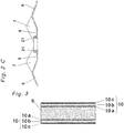
Fig. 3 is a cross-sectional view depicting a configuration of a fin material employed in the fin-tube heat exchanger according to the first embodiment. -
Fig. 4 is an explanatory view depicting a state where condensed water accumulates in a corrugated fin of a fin-tube heat exchanger according to a comparative example of the first embodiment. -
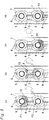
Fig. 5 is an explanatory view depicting a condensed water drainage action that takes place in the corrugated fin of the fin-tube heat exchanger according to the first embodiment. -
Fig. 6 is a cross-sectional view depicting a detailed configuration of a groove portion defined in the fin-tube heat exchanger according to the first embodiment. -
Fig. 7 is a cross-sectional view depicting another detailed configuration of the groove portion defined in the fin-tube heat exchanger according to the first embodiment. -
Fig. 8 is a top plan view of a corrugated fin of a fin-tube heat exchanger according to a second embodiment of the present invention. -
Fig. 9A is a top plan view of a corrugated fin of a fin-tube heat exchanger according to a third embodiment of the present invention. -
Fig. 9B is a cross-sectional view of the corrugated fin ofFig. 9A taken along a line A-A. -
Fig. 9C is a cross-sectional view of the corrugated fin ofFig. 9A taken along a line B-B. -
Fig. 10 is a top plan view of a fin of a conventional fin-tube heat exchanger. - A first aspect of the invention is directed to a fin-tube heat exchanger comprising: a plurality of fins arrayed parallel to one another to form flow paths of a gas therebetween; and a heat-transfer tube extending through the plurality of fins to allow a fluid to flow through the heat-transfer tube for heat exchange with the gas; each of the fins comprising; a plurality of first inclined portions that incline with respect to a direction of airflow so as to form at least one ridge portion; a plurality of tube-surrounding portions located around the heat-transfer tube that extends through each of the fins at a first position and a second position spaced away from each other in a direction of gravitational force; and a plurality of second inclined portions that incline with respect to the direction of airflow, the second inclined portions connecting the tube-surrounding portions and the first inclined portions together, wherein each of the first inclined portions includes a groove portion defined in a surface thereof to connect the second inclined portion at the first position to the second inclined portion at the second position.
- This configuration can efficiently introduce condensed water downwardly in the direction of gravitational force through the groove portion from the second inclined portion where the condensed water mainly accumulates (or from the tube-surrounding portion through the second inclined portion). That is, the condensed water accumulating on the second inclined portion at the first position can be efficiently introduced to another second inclined portion at the second position, which is positioned downwardly of the first position in the direction of gravitational force, through the groove portion. Accordingly, a fin-tube heat exchanger can be provided that can enhance the drainage performance of the condensed water adhering to the fin surfaces and restrain a bridge from being generated between adjacent fins and is superior in energy efficiency. Also, the groove portion can be formed through a comparatively simple working process, thus making it possible to restrain an increase in manufacturing cost associated with the formation of the groove portion.
- A second aspect of the invention is directed to a fin-tube heat exchanger according to the first aspect, wherein the groove portion has an opening of a width dimension of 2 mm or less.
- This configuration creates the effect of the capillary action between the groove portion and the condensed water to thereby further efficiently discharge the condensed water.
- A third aspect of the invention is directed to a fin-tube heat exchanger according to the first or second aspect, wherein in each of the fins, the ridge portion defined by the first inclined portions has a ridge line extending in the direction of gravitational force, and the groove portion extends in the direction of gravitational force.
- This configuration can efficiently discharge the condensed water, which has entered the groove portion, downwardly in the direction of gravitational force.
- A fourth aspect of the invention is directed to a fin-tube heat exchanger according to any one of the first to third aspects, wherein each of the fins comprises a base material and a coating formed on a surface of the base material, and the coating comprises a hydrophilic layer.
- In the presence of the hydrophilic layer, the condensed water accumulating on the tube-surrounding portion or the second inclined portion spreads flatly along the fin surface, thereby making it possible to further restrain the generation of the bridge and easily introduce the condensed water to the groove portion.
- A fifth aspect of the invention is directed to a method of manufacturing the fin-tube heat exchanger according to fourth aspect, comprising: forming the hydrophilic layer on the base material; and subsequently shaping each of the fins by shaping the first inclined portions, the second inclined portions and the groove portion at the same time using the base material.
- In this method, the first inclined portions, the second inclined portions and the groove portion of each fin are shaped at the same time, thus making it possible to provide a fin-tube heat exchanger that is superior in energy efficiency while restraining the manufacturing cost without addition of a new working process.
- Embodiments of the present invention are described hereinafter with reference to the drawings, but the present invention is not limited by the embodiments.
-
Fig. 1 depicts a perspective view of a fin-tube heat exchanger according to a first embodiment of the present invention. As shown inFig. 1 , the fin-tube heat exchanger 100 according to the first embodiment includes a plurality offins 1 arrayed parallel to one another at predetermined intervals to form flow paths of air A (a gas) and a heat-transfer tube 21 extending through thesefins 1. The fin-tube heat exchanger is configured to exchange heat between a medium B flowing through the heat-transfer tube 21 and the air A flowing along surfaces of thefins 1. - A refrigerant such as, for example, carbon dioxide or hydrofluorocarbon is employed as the medium B. The heat-
transfer tube 21 may be made up of only one tube or branched into a plurality of tubes. -
Figs. 2A ,2B and2C depict a detailed configuration of eachfin 1 according to the first embodiment. As shown inFig. 2A , thefin 1 is formed with at least oneridge portion 3 that appears with respect to a direction of airflow S. Specifically, thefin 1 has tworidge portions 3 with respect to the direction of airflow S and, as shown in a cross-sectional view ofFig. 2B , thefin 1 is formed as a corrugated fin having a cross-sectional shape generally in the form of an M. - Also, as shown in
Figs. 2B and2C , thefin 1 is provided with a plurality of tube-surroundingportions 5, a plurality of firstinclined portions 6 that incline with respect to the direction of airflow S so as to form theridge portions 3, and a plurality of secondinclined portions 7 that connect the tube-surroundingportions 5 and the firstinclined portions 6 together. - As shown in
Fig. 2B , the tworidge portions 3 and ahollow portion 4 positioned therebetween are formed by alternately connecting the firstinclined portions 6 having different inclined angles with respect to the direction of airflow S. In thefin 1 according to the first embodiment, ridge lines of theridge portions 3 and thehollow portion 4 are formed so as to extend along the direction of gravitational force. - Each tube-surrounding
portion 5 is an annular portion disposed so as to surround an associated heat-transfer tube 21 at a location where the heat-transfer tube 21 penetrates thefin 1. As shown inFig. 2C , in the first embodiment, the tube-surroundingportion 5 is formed as a plane or planar surface extending along the direction of airflow S. Also, as shown inFig. 2A , the heat-transfer tube 21 penetrates eachfin 1 at a plurality of locations spaced away from one another in the direction of gravitational force. The tube-surroundingportions 5 are provided at the locations where the heat-transfer tube 21 penetrates thefin 1. - Each second
inclined portion 7 is a portion provided around one of the tube-surroundingportions 5. As shown inFig. 2C , each planar tube-surroundingportion 5 and each firstinclined portion 6 having an inclined surface are connected to each other by one of the secondinclined portions 7 having an inclined surface. Accordingly, as shown inFig. 2C , a hollowed region surrounded by the inclined surfaces of the secondinclined portions 7 is formed around the location where the heat-transfer tube 21 penetrates thefin 1. The hollowed region is a region where condensed water is apt to accumulate. - The
fin 1 according to the first embodiment has a plurality of recessedgroove portions 8 defined therein to discharge condensed water that has accumulated on the secondinclined portions 7. Specifically, the recessedgroove portions 8 are formed in the surfaces of a pair of firstinclined portions 6, which form thehollow portion 4, so as to extend in the direction of gravitational force. Each of thegroove portions 8 is formed in the vicinity of thehollow portion 4 along an associated one of theridge portions 3 and thehollow portion 4. - Also, as shown in
Fig. 2A , two adjacent hollow regions (second inclined portions 7) formed around the heat-transfer tube 21, which extends through thefin 1 at a first position P1 and at a second position P2 spaced away from each other in the direction of gravitational force, are connected to each other by the plurality ofgroove portions 8. That is, eachgroove portion 8 is formed so as to extend in the direction of gravitational force to connect the hollow regions that are adjacent to each other in the direction of gravitational force and each surrounded by the secondinclined portion 7. Preferably, thegroove portion 8 is such that at least a portion of a hollow cross-sectional surface thereof is open into the secondinclined portion 7 at a connecting portion with the secondinclined portion 7. - When it comes to the surface material of the
fin 1, it is preferred that a metal having a water contact angle of 30 degrees or less be used. Also, an oxide layer or corrosion product is formed on the metal if the metal is exposed to air or moisture and, accordingly, in a surface treatment of a base material of thefin 1, a hydrophilic coating is preferably formed on respective surfaces of the base material. - In this case, as shown in
Fig. 3 , abase material 9 having acoating 10 on respective surfaces thereof is used. Thecoating 10 is made up of a corrosion-resistant layer 10a, ahydrophilic layer 10b laminated on the corrosion-resistant layer 10a, and a lubricant layer 10c laminated on thehydrophilic layer 10b. A ferrous material, a copper material or an aluminum material can be used for thebase material 9. - The corrosion-resistant layer 10a is formed through a chromate-phosphate treatment, while an inorganic (liquid glass-based or boehmite-based) layer, an organic resin-based layer, or an organic-inorganic composite layer can be used as the
hydrophilic layer 10b. In the first embodiment, a silica/resin-based composite layer that is an organic-inorganic composite layer and has been formed through a chemical conversion treatment is used as thehydrophilic layer 10b. - Also, the lubricant layer 10c is intended to enhance the lubricating property when the fin material is pressed into the
fin 1. If a water-soluble layer is used as the lubricant layer 10c, it readily disappears in the presence of condensed water generated on thefin 1. Accordingly, the hydrophilic property of thehydrophilic layer 10b is not lowered by the lubricant layer 10c formed thereon. - If at least one of the plurality of layers of the
coating 10 is made up of thehydrophilic layer 10b in the above-described manner, the condensed water spreads flatly along the fin surfaces, thus making it possible to restrain a bridge from being generated between adjacent fins land to readily lead the condensed water to thegroove portions 8 in a manner explained later. - In the fin-
tube heat exchanger 100 of the above-described construction according to the first embodiment, the action and operation of discharging the condensed water adhering to thefins 1 are explained hereinafter. -
Fig. 4 is a top plan view of afin 1 having nogroove portions 8 in a fin-tube heat exchanger according to a comparative example of the first embodiment. The same component parts other than thegroove portions 8 as those in thefin 1 according to the first embodiment are designated by the same reference numbers and explanation thereof is omitted. - As shown in
Fig. 4 , in the fin-tube heat exchanger with nogroove portions 8 according to the comparative example,condensed water 13 generated particularly around the heat-transfer tube 21 flows gradually downwardly along the surface of thefin 1 in the direction of gravitational force. This condensed water cannot climb over theridge portion 3 positioned at the boundary with the firstinclined portion 6 and gradually accumulates on the tube-surroundingportion 5 and the secondinclined portion 7. - Upon further generation of the
condensed water 13, the amount of accumulated condensed water increases and a bridge is generated betweenadjacent fins 1 to block a space between them. As a result, the airflow resistance increases and the heat-transfer area of the fin to be utilized for heat exchange with air reduces, thereby giving rise to a reduction in energy efficiency. - An operation of discharging the condensed water in the
fin 1 according to the first embodiment is explained hereinafter with reference toFig. 5 . InFig. 5,(a), (b), (c) and (d) are shown in order of time from the left. Firstly, as shown inFig. 5(a) , when thecondensed water 13 begins accumulating on the secondinclined portions 7 at the first position P1, as shown inFig. 5(b) , the accumulated condensed water is introduced into and passes through thegroove portions 8, which are respectively connected to lower portions of the secondinclined portions 7 in the direction of gravitational force, and is then introduced to the secondinclined portions 7 at the second position P2 adjacent to the first position P1 in the direction of gravitational force. Such a condensed water-introducing action of thegroove portions 8 conveys thecondensed water 13 from the tube-surroundingportion 5 and the secondinclined portions 7 both positioned at an upper portion (position P1) in the direction of gravitational force to the next tube-surroundingportion 5 and the next secondinclined portions 7 both positioned at a lower portion (position P2) in the direction of gravitational force (Fig. 5(c) ). The condensed water-introducing action of thegroove portions 8 is repeatedly conducted to thereby convey thecondensed water 13 further downwardly (Fig. 5(d) ). - In this way, the condensed water-introducing action of the
groove portions 8 can rapidly discharge thecondensed water 13 accumulating on the tube-surroundingportion 5 and the secondinclined portions 7, thus making it possible to dramatically enhance the drainage performance of thefin 1. - Although in this first embodiment the
groove portions 8 have been described as being formed so as to connect the secondinclined portions 7 adjacent to each other in the direction of gravitational force, thegroove portions 8 may be at least held in contact with the secondinclined portions 7 formed at a lower portion of the heat-transfer tube 21 in the direction of gravitational force to introduce the condensed water accumulating on the secondinclined portions 7 downwardly in the direction of gravitational force. - Although in the first embodiment two
parallel groove portions 8 are formed along the ridge lines of theridge portions 3 formed by the firstinclined portions 6, one or more than three groove portions may be formed. Also, in the first embodiment, thegroove portions 8 are formed to avoid the ridge lines of theridge portions 3 or thehollow portions 4 formed by the firstinclined portions 6, but the groove portions may be formed on the ridge lines by further hollowing theridge portions 3 or thehollow portions 4. - As shown in
Fig. 6 , a width dimension L of an opening of eachgroove portion 8 is preferably 2 mm or less to make use of the capillary action and, in order to further enhance the effect of the capillary action, the width dimension L is preferably 0.5 mm or less. By employing such an opening width dimension, the action of thegroove portions 8 for introducing thecondensed water 13 can be significantly enhanced. - Although the shape of each
groove portion 8 as shown inFig. 6 has inclined side surfaces 8a in consideration of a reduction in airflow resistance of air passing between thefins 1, as shown inFig. 7 , thegroove portion 8 may have vertically extending side surfaces 8a. Alternatively, thegroove portion 8 may be sharpened downwardly (in the form of a V) so as to have opposite side surfaces 8a that meet at a bottom portion 8b. - In manufacturing the
fins 1 of the above-described configuration according to the first embodiment, the firstinclined portions 6, the secondinclined portions 7 and thegroove portions 8 can be shaped at the same time by pressing a base material having coatings formed thereon. Accordingly, an inexpensive fin-tube heat exchanger that is superior in drainage property can be manufactured without addition of a new working process. -
Fig. 8 is a top plan view of a fin of a fin-tube heat exchanger according to a second embodiment of the present invention. In the second embodiment, the same component parts as those in the first embodiment referred to above are designated by the same reference numbers and explanation thereof is omitted. - The second embodiment differs from the first embodiment in that the
groove portions 8 are provided in the vicinity of theridge portions 3 of eachfin 1. - As shown in
Fig. 8 , eachgroove portion 8 is formed so as to connect two secondinclined portions 7 adjacent to each other in the direction of gravitational force along one of theridge portions 3 of thefin 1. - In this configuration, because a lower end of each second
inclined portion 7 in the direction of gravitational force is held in contact with an upper end of thegroove portion 8,condensed water 13 accumulating on the secondinclined portion 7 can be smoothly introduced downwardly. -
Fig. 9A is a top plan view of a corrugated fin of a fin-tube heat exchanger according to a third embodiment of the present invention.Figs. 9B and9C are cross-sectional views of the corrugated fin. In the third embodiment, the same component parts as those in the first embodiment referred to above are designated by the same reference numbers and explanation thereof is omitted. - The third embodiment differs from the first embodiment in that, as shown in
Figs. 9B and9C , eachfin 15 is formed as a corrugated fin having a cross-sectional shape generally in the form of an inverted V (that is, thefin 15 has only oneridge portion 3 formed thereon). - As shown in
Fig. 9A , eachgroove portion 8 is formed so as to connect two secondinclined portions 7 adjacent to each other in the direction of gravitational force along theridge portion 3 of thefin 15. - In general, a V-shaped corrugated fin can be formed so as to have a larger surface area than that of an M-shaped corrugated fin and is accordingly likely to have an increased heat exchanging performance.
- On the other hand, the V-shaped corrugated fin is provided with the flat tube-surrounding
portions 5 and the secondinclined portions 7 both having larger areas as those of the M-shaped corrugated fin and, accordingly, the area where thecondensed water 13 accumulates becomes large, thus posing a problem that thecondensed water 13 is likely to accumulate. - Therefore, the
condensed water 13 can be smoothly introduced downwardly in the direction of gravitational force by providing thegroove portions 8 in the manner as set forth in the third embodiment, thus making it possible to realize a V-shaped corrugate fin that has an enhanced heat exchanging performance and is superior in drainage performance. - Although in the above explanation the
groove portions 8 have been described as extending in the direction of gravitational force, it is sufficient if the groove portions continuously have components directed downwardly in the direction of gravitational force. By way of example, the groove portions may be inclined or curved with respect to the direction of gravitational force. - Although in the above explanation the groove portions formed in the fin surfaces have been also described as being able to enhance the drainage property of the condensed water adhering to the fin surfaces, the groove portions can enhance the drainage property of a liquid adhering to the fin surfaces as well as the condensed water.
- Although in the above explanation an example is taken in which a heat medium exchanges heat with air passing through a fin-tube heat exchanger, the heat medium may exchange heat with a gas passing through the fin-tube heat exchanger as well as the air.
- Although the present invention has been fully described by way of preferred embodiments with reference to the accompanying drawings, it is to be noted here that various changes and modifications will be apparent to those skilled in the art. Therefore, unless such changes and modifications otherwise depart from the scope of the present invention as set forth in the appended claims, they should be construed as being included therein.
- As described above, because the fin-tube heat exchanger according to the present invention has the groove portions formed in the fin surfaces to enhance the drainage property, the fin-tube heat exchanger according to the present invention can be utilized as a heat exchanger for use in an air conditioner, a water heater, a heating appliance or the like.
-
- 1, 15
- fin (corrugated fin)
- 3
- ridge portion
- 4
- hollow portion
- 5
- tube-surrounding portion
- 6
- first inclined portion
- 7
- second inclined portion
- 8
- groove portion
- 9
- base material
- 10
- coating
- 10a
- corrosion-resistant layer
- 10b
- hydrophilic layer
- 10c
- lubricant layer
- 13
- condensed water
- 21
- heat-transfer tube
- 100
- fin-tube heat exchanger
- P1
- first position
- P2
- second position
- S
- direction of airflow
- L
- width dimension of opening
Claims (5)
- A fin-tube heat exchanger (100) comprising:a plurality of fins (1; 15) arrayed parallel to one another to form flow paths of a gas there between; anda heat-transfer tube (21) extending through the plurality of fins (1; 15) to allow a fluid to flow through the heat-transfer tube (21) for heat exchange with the gas;each of the fins (1;15) comprising;a plurality of first inclined portions (6) that incline with respect to a direction of airflow so as to form at least one ridge portion (3);a plurality of tube-surrounding portions (5) located around the heat-transfer tube (21) that extends through each of the fins (1; 15) at a first position (P1) and a second position (P2) spaced away from each other in a direction of gravitational force; anda plurality of second inclined portions (7) that incline with respect to the direction of airflow, the second inclined (7) portions connecting the tube-surrounding portions (5) and the first inclined (6) portions together,characterized in that each of the first inclined portions (6) includes a groove portion (8) defined in a surface thereof to connect the second inclined portion (7) at the first position (P1) to the second inclined portion (7) at the second position (P2).
- The fin-tube heat exchanger according to claim 1, wherein the groove portion (8) has an opening of a width dimension of 2 mm or less.
- The fin-tube heat exchanger according to claim 1 or 2, wherein in each of the fins (1; 15), the ridge portion (3) defined by the first inclined portions (6) has a ridge line extending in the direction of gravitational force, and the groove portion (8) extends in the direction of gravitational force.
- The fin-tube heat exchanger according to any one of claims 1 to 3, wherein each of the fins (1; 15) comprises a base material (9) and a coating (10) formed on a surface of the base material (9), and the coating (10) comprises a hydrophilic layer (10b).
- A method of manufacturing the fin-tube heat exchanger according to claim 4, comprising:forming the hydrophilic layer on the base material; andsubsequently shaping each of the fins by shaping the first inclined portions, the second inclined portions and the groove portion at the same time using the base material.
Applications Claiming Priority (2)
| Application Number | Priority Date | Filing Date | Title |
|---|---|---|---|
| JP2012097380 | 2012-04-23 | ||
| PCT/JP2013/002710 WO2013161263A1 (en) | 2012-04-23 | 2013-04-22 | Fin tube heat exchanger and method for manufacturing same |
Publications (3)
| Publication Number | Publication Date |
|---|---|
| EP2843346A1 EP2843346A1 (en) | 2015-03-04 |
| EP2843346A4 EP2843346A4 (en) | 2015-06-03 |
| EP2843346B1 true EP2843346B1 (en) | 2018-12-26 |
Family
ID=49482606
Family Applications (1)
| Application Number | Title | Priority Date | Filing Date |
|---|---|---|---|
| EP13781866.2A Active EP2843346B1 (en) | 2012-04-23 | 2013-04-22 | Fin-tube heat exchanger and method of manufacturing the same |
Country Status (4)
| Country | Link |
|---|---|
| EP (1) | EP2843346B1 (en) |
| JP (1) | JP6128492B2 (en) |
| CN (1) | CN103857974B (en) |
| WO (1) | WO2013161263A1 (en) |
Families Citing this family (12)
| Publication number | Priority date | Publication date | Assignee | Title |
|---|---|---|---|---|
| JP6449032B2 (en) * | 2015-01-28 | 2019-01-09 | アクア株式会社 | COOLER, MANUFACTURING METHOD THEREOF, AND REFRIGERATOR HAVING THE COOLER |
| CN106066133A (en) * | 2016-06-22 | 2016-11-02 | 上海和衡能源科技发展有限公司 | Single-tube fin type heat exchanger and assembling thereof |
| DE102017120124A1 (en) * | 2017-09-01 | 2019-03-07 | Miele & Cie. Kg | Finned tube heat exchanger |
| DE102017120123A1 (en) * | 2017-09-01 | 2019-03-07 | Miele & Cie. Kg | Finned tube heat exchanger |
| CN108613232B (en) * | 2018-05-28 | 2024-08-30 | 广东美的厨房电器制造有限公司 | Heat exchanger for refrigeration hood and refrigeration hood having the same |
| CN111981583B (en) * | 2020-08-14 | 2021-12-07 | 青岛海信日立空调系统有限公司 | Outdoor unit of air conditioner |
| CN114526614B (en) * | 2022-02-28 | 2023-12-15 | 四川奥格莱能源科技有限公司 | High-temperature high-pressure multi-tube condensing type steam heat exchanger |
| JP7436895B1 (en) | 2022-08-12 | 2024-02-22 | ダイキン工業株式会社 | Heat exchanger |
| JP7453578B2 (en) * | 2022-08-12 | 2024-03-21 | ダイキン工業株式会社 | Heat exchanger |
| KR20240115602A (en) | 2023-01-19 | 2024-07-26 | 엘지전자 주식회사 | Heat exchanger |
| CN119436894B (en) * | 2024-10-28 | 2025-09-19 | 广东美的制冷设备有限公司 | Heat exchanger fins and heat exchanger |
| CN121932692A (en) * | 2024-10-28 | 2026-04-28 | 广东美的制冷设备有限公司 | Heat exchange device and air conditioning device |
Family Cites Families (20)
| Publication number | Priority date | Publication date | Assignee | Title |
|---|---|---|---|---|
| JPH053910Y2 (en) | 1987-07-28 | 1993-01-29 | ||
| JP2834339B2 (en) * | 1991-02-21 | 1998-12-09 | 松下電器産業株式会社 | Finned heat exchanger |
| JPH05322470A (en) * | 1992-05-28 | 1993-12-07 | Hitachi Ltd | Heat exchanger |
| JPH07280480A (en) * | 1994-04-01 | 1995-10-27 | Daikin Ind Ltd | Heat exchanger for outdoor unit |
| JPH0886584A (en) * | 1994-09-20 | 1996-04-02 | Fujitsu General Ltd | Heat exchanger with fins |
| JP2983861B2 (en) * | 1994-11-18 | 1999-11-29 | 古河電気工業株式会社 | Aluminum fin material for heat exchangers with excellent odor and moldability |
| JP3358355B2 (en) * | 1994-12-22 | 2002-12-16 | ダイキン工業株式会社 | Cross fin heat exchanger |
| TW340180B (en) * | 1995-09-14 | 1998-09-11 | Sanyo Electric Co | Heat exchanger having corrugated fins and air conditioner having the same |
| JPH10281674A (en) * | 1997-04-07 | 1998-10-23 | Daikin Ind Ltd | Cross fin heat exchanger for outdoor units |
| JP2000193389A (en) * | 1998-12-28 | 2000-07-14 | Hitachi Ltd | Outdoor unit of air conditioner |
| JP4497394B2 (en) * | 2001-04-20 | 2010-07-07 | 日立アプライアンス株式会社 | Heat exchanger and air conditioner |
| CA2391077A1 (en) * | 2001-06-28 | 2002-12-28 | York International Corporation | High-v plate fin for a heat exchanger and a method of manufacturing |
| JP2003314980A (en) * | 2002-04-18 | 2003-11-06 | Toyo Radiator Co Ltd | High-temperature plate fin heat exchanger |
| US7261147B2 (en) * | 2003-05-28 | 2007-08-28 | Lg Electronics Inc. | Heat exchanger |
| KR100555415B1 (en) * | 2003-05-28 | 2006-02-24 | 엘지전자 주식회사 | heat transmitter |
| JP2006138504A (en) * | 2004-11-10 | 2006-06-01 | Mitsubishi Heavy Ind Ltd | Heat exchanger and air conditioner |
| JP2006336904A (en) * | 2005-05-31 | 2006-12-14 | Matsushita Electric Ind Co Ltd | Heat exchanger and manufacturing method thereof |
| JP4169079B2 (en) * | 2006-10-02 | 2008-10-22 | ダイキン工業株式会社 | Finned tube heat exchanger |
| JP5417718B2 (en) * | 2007-03-07 | 2014-02-19 | ダイキン工業株式会社 | Heat exchanger |
| JP2010175131A (en) | 2009-01-29 | 2010-08-12 | Mitsubishi Electric Corp | Heat exchange device, refrigerating air conditioner and method of manufacturing heat exchanger |
-
2013
- 2013-04-22 JP JP2014512348A patent/JP6128492B2/en active Active
- 2013-04-22 EP EP13781866.2A patent/EP2843346B1/en active Active
- 2013-04-22 WO PCT/JP2013/002710 patent/WO2013161263A1/en not_active Ceased
- 2013-04-22 CN CN201380003502.3A patent/CN103857974B/en active Active
Non-Patent Citations (1)
| Title |
|---|
| None * |
Also Published As
| Publication number | Publication date |
|---|---|
| JPWO2013161263A1 (en) | 2015-12-21 |
| JP6128492B2 (en) | 2017-05-17 |
| WO2013161263A1 (en) | 2013-10-31 |
| EP2843346A4 (en) | 2015-06-03 |
| CN103857974B (en) | 2018-03-16 |
| EP2843346A1 (en) | 2015-03-04 |
| CN103857974A (en) | 2014-06-11 |
Similar Documents
| Publication | Publication Date | Title |
|---|---|---|
| EP2843346A1 (en) | Fin tube heat exchanger and method for manufacturing same | |
| US9459053B2 (en) | Heat exchanger and air-conditioning apparatus | |
| CN103874901B (en) | Finned tube heat exchanger | |
| AU2011279513B2 (en) | Evaporative heat exchange apparatus with finned elliptical tube coil assembly | |
| US9534827B2 (en) | Air heat exchanger | |
| CN105190216B (en) | Fin tubing heat exchanger and freezing cycle device | |
| US8613307B2 (en) | Finned tube heat exchanger | |
| CN106716042A (en) | Heat exchanger and method for manufacturing plate fins of heat exchanger | |
| CN104089517B (en) | Fin for heat exchanger and heat exchanger with fin | |
| CN1307400C (en) | Heat exchanger | |
| CN105556234A (en) | Multiport Extrusion (MPE) Design | |
| CN103492826A (en) | Heat exchanger | |
| JP6391969B2 (en) | Heat exchanger and air conditioner | |
| JP5974276B2 (en) | Finned tube heat exchanger | |
| JP2009121708A (en) | Heat exchanger | |
| WO2013161290A1 (en) | Finned tube heat exchanger | |
| CN103717993B (en) | Finned Tube Heat Exchanger | |
| CN203964745U (en) | Fin for heat exchanger and heat exchanger having same | |
| JP2013120044A (en) | Fin tube heat exchanger and method for manufacturing same | |
| CN204063690U (en) | Automobile air-conditioning evaporator | |
| CN104246408B (en) | Fin-tube heat exchanger | |
| JP2020139690A (en) | Heat exchanger of air conditioner | |
| KR101150932B1 (en) | Inner fin of heat exchanger | |
| JP6523557B2 (en) | Heat exchanger and heat pump device | |
| KR20080057070A (en) | heat transmitter |
Legal Events
| Date | Code | Title | Description |
|---|---|---|---|
| PUAI | Public reference made under article 153(3) epc to a published international application that has entered the european phase |
Free format text: ORIGINAL CODE: 0009012 |
|
| 17P | Request for examination filed |
Effective date: 20140324 |
|
| AK | Designated contracting states |
Kind code of ref document: A1 Designated state(s): AL AT BE BG CH CY CZ DE DK EE ES FI FR GB GR HR HU IE IS IT LI LT LU LV MC MK MT NL NO PL PT RO RS SE SI SK SM TR |
|
| AX | Request for extension of the european patent |
Extension state: BA ME |
|
| RA4 | Supplementary search report drawn up and despatched (corrected) |
Effective date: 20150504 |
|
| RIC1 | Information provided on ipc code assigned before grant |
Ipc: F28D 21/00 20060101ALI20150427BHEP Ipc: F28F 1/30 20060101ALI20150427BHEP Ipc: F28F 1/32 20060101AFI20150427BHEP Ipc: F25B 39/02 20060101ALI20150427BHEP Ipc: F28D 1/047 20060101ALI20150427BHEP Ipc: F28F 17/00 20060101ALI20150427BHEP |
|
| DAX | Request for extension of the european patent (deleted) | ||
| GRAP | Despatch of communication of intention to grant a patent |
Free format text: ORIGINAL CODE: EPIDOSNIGR1 |
|
| STAA | Information on the status of an ep patent application or granted ep patent |
Free format text: STATUS: GRANT OF PATENT IS INTENDED |
|
| RIC1 | Information provided on ipc code assigned before grant |
Ipc: F28D 1/047 20060101ALI20180529BHEP Ipc: F28F 1/32 20060101AFI20180529BHEP Ipc: F28D 21/00 20060101ALI20180529BHEP Ipc: F25B 39/02 20060101ALI20180529BHEP Ipc: F28F 1/30 20060101ALI20180529BHEP Ipc: F28F 17/00 20060101ALI20180529BHEP |
|
| INTG | Intention to grant announced |
Effective date: 20180612 |
|
| GRAS | Grant fee paid |
Free format text: ORIGINAL CODE: EPIDOSNIGR3 |
|
| GRAA | (expected) grant |
Free format text: ORIGINAL CODE: 0009210 |
|
| STAA | Information on the status of an ep patent application or granted ep patent |
Free format text: STATUS: THE PATENT HAS BEEN GRANTED |
|
| RIN1 | Information on inventor provided before grant (corrected) |
Inventor name: HONMA, MASAYA Inventor name: OKAICHI, ATSUO Inventor name: SUKAWA, TORU Inventor name: OHTSUBO, SHUHEI Inventor name: NAGOSHI, KENJI Inventor name: YOKOYAMA, SHOICHI Inventor name: HIROTA, MASANOBU |
|
| AK | Designated contracting states |
Kind code of ref document: B1 Designated state(s): AL AT BE BG CH CY CZ DE DK EE ES FI FR GB GR HR HU IE IS IT LI LT LU LV MC MK MT NL NO PL PT RO RS SE SI SK SM TR |
|
| REG | Reference to a national code |
Ref country code: GB Ref legal event code: FG4D |
|
| REG | Reference to a national code |
Ref country code: CH Ref legal event code: EP |
|
| REG | Reference to a national code |
Ref country code: AT Ref legal event code: REF Ref document number: 1081997 Country of ref document: AT Kind code of ref document: T Effective date: 20190115 |
|
| REG | Reference to a national code |
Ref country code: DE Ref legal event code: R096 Ref document number: 602013048858 Country of ref document: DE |
|
| REG | Reference to a national code |
Ref country code: IE Ref legal event code: FG4D |
|
| PG25 | Lapsed in a contracting state [announced via postgrant information from national office to epo] |
Ref country code: LV Free format text: LAPSE BECAUSE OF FAILURE TO SUBMIT A TRANSLATION OF THE DESCRIPTION OR TO PAY THE FEE WITHIN THE PRESCRIBED TIME-LIMIT Effective date: 20181226 Ref country code: LT Free format text: LAPSE BECAUSE OF FAILURE TO SUBMIT A TRANSLATION OF THE DESCRIPTION OR TO PAY THE FEE WITHIN THE PRESCRIBED TIME-LIMIT Effective date: 20181226 Ref country code: BG Free format text: LAPSE BECAUSE OF FAILURE TO SUBMIT A TRANSLATION OF THE DESCRIPTION OR TO PAY THE FEE WITHIN THE PRESCRIBED TIME-LIMIT Effective date: 20190326 Ref country code: HR Free format text: LAPSE BECAUSE OF FAILURE TO SUBMIT A TRANSLATION OF THE DESCRIPTION OR TO PAY THE FEE WITHIN THE PRESCRIBED TIME-LIMIT Effective date: 20181226 Ref country code: FI Free format text: LAPSE BECAUSE OF FAILURE TO SUBMIT A TRANSLATION OF THE DESCRIPTION OR TO PAY THE FEE WITHIN THE PRESCRIBED TIME-LIMIT Effective date: 20181226 Ref country code: NO Free format text: LAPSE BECAUSE OF FAILURE TO SUBMIT A TRANSLATION OF THE DESCRIPTION OR TO PAY THE FEE WITHIN THE PRESCRIBED TIME-LIMIT Effective date: 20190326 |
|
| REG | Reference to a national code |
Ref country code: NL Ref legal event code: MP Effective date: 20181226 |
|
| REG | Reference to a national code |
Ref country code: LT Ref legal event code: MG4D |
|
| PG25 | Lapsed in a contracting state [announced via postgrant information from national office to epo] |
Ref country code: RS Free format text: LAPSE BECAUSE OF FAILURE TO SUBMIT A TRANSLATION OF THE DESCRIPTION OR TO PAY THE FEE WITHIN THE PRESCRIBED TIME-LIMIT Effective date: 20181226 Ref country code: GR Free format text: LAPSE BECAUSE OF FAILURE TO SUBMIT A TRANSLATION OF THE DESCRIPTION OR TO PAY THE FEE WITHIN THE PRESCRIBED TIME-LIMIT Effective date: 20190327 Ref country code: SE Free format text: LAPSE BECAUSE OF FAILURE TO SUBMIT A TRANSLATION OF THE DESCRIPTION OR TO PAY THE FEE WITHIN THE PRESCRIBED TIME-LIMIT Effective date: 20181226 Ref country code: AL Free format text: LAPSE BECAUSE OF FAILURE TO SUBMIT A TRANSLATION OF THE DESCRIPTION OR TO PAY THE FEE WITHIN THE PRESCRIBED TIME-LIMIT Effective date: 20181226 |
|
| REG | Reference to a national code |
Ref country code: AT Ref legal event code: MK05 Ref document number: 1081997 Country of ref document: AT Kind code of ref document: T Effective date: 20181226 |
|
| PG25 | Lapsed in a contracting state [announced via postgrant information from national office to epo] |
Ref country code: NL Free format text: LAPSE BECAUSE OF FAILURE TO SUBMIT A TRANSLATION OF THE DESCRIPTION OR TO PAY THE FEE WITHIN THE PRESCRIBED TIME-LIMIT Effective date: 20181226 |
|
| PG25 | Lapsed in a contracting state [announced via postgrant information from national office to epo] |
Ref country code: ES Free format text: LAPSE BECAUSE OF FAILURE TO SUBMIT A TRANSLATION OF THE DESCRIPTION OR TO PAY THE FEE WITHIN THE PRESCRIBED TIME-LIMIT Effective date: 20181226 Ref country code: PT Free format text: LAPSE BECAUSE OF FAILURE TO SUBMIT A TRANSLATION OF THE DESCRIPTION OR TO PAY THE FEE WITHIN THE PRESCRIBED TIME-LIMIT Effective date: 20190426 Ref country code: IT Free format text: LAPSE BECAUSE OF FAILURE TO SUBMIT A TRANSLATION OF THE DESCRIPTION OR TO PAY THE FEE WITHIN THE PRESCRIBED TIME-LIMIT Effective date: 20181226 Ref country code: CZ Free format text: LAPSE BECAUSE OF FAILURE TO SUBMIT A TRANSLATION OF THE DESCRIPTION OR TO PAY THE FEE WITHIN THE PRESCRIBED TIME-LIMIT Effective date: 20181226 Ref country code: PL Free format text: LAPSE BECAUSE OF FAILURE TO SUBMIT A TRANSLATION OF THE DESCRIPTION OR TO PAY THE FEE WITHIN THE PRESCRIBED TIME-LIMIT Effective date: 20181226 |
|
| PG25 | Lapsed in a contracting state [announced via postgrant information from national office to epo] |
Ref country code: RO Free format text: LAPSE BECAUSE OF FAILURE TO SUBMIT A TRANSLATION OF THE DESCRIPTION OR TO PAY THE FEE WITHIN THE PRESCRIBED TIME-LIMIT Effective date: 20181226 Ref country code: SK Free format text: LAPSE BECAUSE OF FAILURE TO SUBMIT A TRANSLATION OF THE DESCRIPTION OR TO PAY THE FEE WITHIN THE PRESCRIBED TIME-LIMIT Effective date: 20181226 Ref country code: IS Free format text: LAPSE BECAUSE OF FAILURE TO SUBMIT A TRANSLATION OF THE DESCRIPTION OR TO PAY THE FEE WITHIN THE PRESCRIBED TIME-LIMIT Effective date: 20190426 Ref country code: EE Free format text: LAPSE BECAUSE OF FAILURE TO SUBMIT A TRANSLATION OF THE DESCRIPTION OR TO PAY THE FEE WITHIN THE PRESCRIBED TIME-LIMIT Effective date: 20181226 Ref country code: SM Free format text: LAPSE BECAUSE OF FAILURE TO SUBMIT A TRANSLATION OF THE DESCRIPTION OR TO PAY THE FEE WITHIN THE PRESCRIBED TIME-LIMIT Effective date: 20181226 |
|
| REG | Reference to a national code |
Ref country code: DE Ref legal event code: R097 Ref document number: 602013048858 Country of ref document: DE |
|
| PG25 | Lapsed in a contracting state [announced via postgrant information from national office to epo] |
Ref country code: DK Free format text: LAPSE BECAUSE OF FAILURE TO SUBMIT A TRANSLATION OF THE DESCRIPTION OR TO PAY THE FEE WITHIN THE PRESCRIBED TIME-LIMIT Effective date: 20181226 Ref country code: AT Free format text: LAPSE BECAUSE OF FAILURE TO SUBMIT A TRANSLATION OF THE DESCRIPTION OR TO PAY THE FEE WITHIN THE PRESCRIBED TIME-LIMIT Effective date: 20181226 |
|
| PLBE | No opposition filed within time limit |
Free format text: ORIGINAL CODE: 0009261 |
|
| STAA | Information on the status of an ep patent application or granted ep patent |
Free format text: STATUS: NO OPPOSITION FILED WITHIN TIME LIMIT |
|
| REG | Reference to a national code |
Ref country code: CH Ref legal event code: PL |
|
| 26N | No opposition filed |
Effective date: 20190927 |
|
| REG | Reference to a national code |
Ref country code: BE Ref legal event code: MM Effective date: 20190430 |
|
| GBPC | Gb: european patent ceased through non-payment of renewal fee |
Effective date: 20190422 |
|
| PG25 | Lapsed in a contracting state [announced via postgrant information from national office to epo] |
Ref country code: MC Free format text: LAPSE BECAUSE OF FAILURE TO SUBMIT A TRANSLATION OF THE DESCRIPTION OR TO PAY THE FEE WITHIN THE PRESCRIBED TIME-LIMIT Effective date: 20181226 Ref country code: LU Free format text: LAPSE BECAUSE OF NON-PAYMENT OF DUE FEES Effective date: 20190422 |
|
| PG25 | Lapsed in a contracting state [announced via postgrant information from national office to epo] |
Ref country code: CH Free format text: LAPSE BECAUSE OF NON-PAYMENT OF DUE FEES Effective date: 20190430 Ref country code: GB Free format text: LAPSE BECAUSE OF NON-PAYMENT OF DUE FEES Effective date: 20190422 Ref country code: LI Free format text: LAPSE BECAUSE OF NON-PAYMENT OF DUE FEES Effective date: 20190430 |
|
| PG25 | Lapsed in a contracting state [announced via postgrant information from national office to epo] |
Ref country code: FR Free format text: LAPSE BECAUSE OF NON-PAYMENT OF DUE FEES Effective date: 20190430 Ref country code: SI Free format text: LAPSE BECAUSE OF FAILURE TO SUBMIT A TRANSLATION OF THE DESCRIPTION OR TO PAY THE FEE WITHIN THE PRESCRIBED TIME-LIMIT Effective date: 20181226 Ref country code: BE Free format text: LAPSE BECAUSE OF NON-PAYMENT OF DUE FEES Effective date: 20190430 |
|
| PG25 | Lapsed in a contracting state [announced via postgrant information from national office to epo] |
Ref country code: TR Free format text: LAPSE BECAUSE OF FAILURE TO SUBMIT A TRANSLATION OF THE DESCRIPTION OR TO PAY THE FEE WITHIN THE PRESCRIBED TIME-LIMIT Effective date: 20181226 |
|
| PG25 | Lapsed in a contracting state [announced via postgrant information from national office to epo] |
Ref country code: IE Free format text: LAPSE BECAUSE OF NON-PAYMENT OF DUE FEES Effective date: 20190422 |
|
| PG25 | Lapsed in a contracting state [announced via postgrant information from national office to epo] |
Ref country code: CY Free format text: LAPSE BECAUSE OF FAILURE TO SUBMIT A TRANSLATION OF THE DESCRIPTION OR TO PAY THE FEE WITHIN THE PRESCRIBED TIME-LIMIT Effective date: 20181226 |
|
| PG25 | Lapsed in a contracting state [announced via postgrant information from national office to epo] |
Ref country code: MT Free format text: LAPSE BECAUSE OF FAILURE TO SUBMIT A TRANSLATION OF THE DESCRIPTION OR TO PAY THE FEE WITHIN THE PRESCRIBED TIME-LIMIT Effective date: 20181226 Ref country code: HU Free format text: LAPSE BECAUSE OF FAILURE TO SUBMIT A TRANSLATION OF THE DESCRIPTION OR TO PAY THE FEE WITHIN THE PRESCRIBED TIME-LIMIT; INVALID AB INITIO Effective date: 20130422 |
|
| PG25 | Lapsed in a contracting state [announced via postgrant information from national office to epo] |
Ref country code: MK Free format text: LAPSE BECAUSE OF FAILURE TO SUBMIT A TRANSLATION OF THE DESCRIPTION OR TO PAY THE FEE WITHIN THE PRESCRIBED TIME-LIMIT Effective date: 20181226 |
|
| PGFP | Annual fee paid to national office [announced via postgrant information from national office to epo] |
Ref country code: DE Payment date: 20250422 Year of fee payment: 13 |