EP2843291A1 - Straight tube type lamp and luminaire - Google Patents
Straight tube type lamp and luminaire Download PDFInfo
- Publication number
- EP2843291A1 EP2843291A1 EP14157883.1A EP14157883A EP2843291A1 EP 2843291 A1 EP2843291 A1 EP 2843291A1 EP 14157883 A EP14157883 A EP 14157883A EP 2843291 A1 EP2843291 A1 EP 2843291A1
- Authority
- EP
- European Patent Office
- Prior art keywords
- terminals
- pair
- cap
- tube type
- straight tube
- Prior art date
- Legal status (The legal status is an assumption and is not a legal conclusion. Google has not performed a legal analysis and makes no representation as to the accuracy of the status listed.)
- Withdrawn
Links
Images




Classifications
-
- F—MECHANICAL ENGINEERING; LIGHTING; HEATING; WEAPONS; BLASTING
- F21—LIGHTING
- F21V—FUNCTIONAL FEATURES OR DETAILS OF LIGHTING DEVICES OR SYSTEMS THEREOF; STRUCTURAL COMBINATIONS OF LIGHTING DEVICES WITH OTHER ARTICLES, NOT OTHERWISE PROVIDED FOR
- F21V23/00—Arrangement of electric circuit elements in or on lighting devices
- F21V23/06—Arrangement of electric circuit elements in or on lighting devices the elements being coupling devices, e.g. connectors
-
- F—MECHANICAL ENGINEERING; LIGHTING; HEATING; WEAPONS; BLASTING
- F21—LIGHTING
- F21K—NON-ELECTRIC LIGHT SOURCES USING LUMINESCENCE; LIGHT SOURCES USING ELECTROCHEMILUMINESCENCE; LIGHT SOURCES USING CHARGES OF COMBUSTIBLE MATERIAL; LIGHT SOURCES USING SEMICONDUCTOR DEVICES AS LIGHT-GENERATING ELEMENTS; LIGHT SOURCES NOT OTHERWISE PROVIDED FOR
- F21K9/00—Light sources using semiconductor devices as light-generating elements, e.g. using light-emitting diodes [LED] or lasers
- F21K9/20—Light sources comprising attachment means
- F21K9/27—Retrofit light sources for lighting devices with two fittings for each light source, e.g. for substitution of fluorescent tubes
-
- F—MECHANICAL ENGINEERING; LIGHTING; HEATING; WEAPONS; BLASTING
- F21—LIGHTING
- F21K—NON-ELECTRIC LIGHT SOURCES USING LUMINESCENCE; LIGHT SOURCES USING ELECTROCHEMILUMINESCENCE; LIGHT SOURCES USING CHARGES OF COMBUSTIBLE MATERIAL; LIGHT SOURCES USING SEMICONDUCTOR DEVICES AS LIGHT-GENERATING ELEMENTS; LIGHT SOURCES NOT OTHERWISE PROVIDED FOR
- F21K9/00—Light sources using semiconductor devices as light-generating elements, e.g. using light-emitting diodes [LED] or lasers
- F21K9/20—Light sources comprising attachment means
- F21K9/27—Retrofit light sources for lighting devices with two fittings for each light source, e.g. for substitution of fluorescent tubes
- F21K9/272—Details of end parts, i.e. the parts that connect the light source to a fitting; Arrangement of components within end parts
-
- F—MECHANICAL ENGINEERING; LIGHTING; HEATING; WEAPONS; BLASTING
- F21—LIGHTING
- F21S—NON-PORTABLE LIGHTING DEVICES; SYSTEMS THEREOF; VEHICLE LIGHTING DEVICES SPECIALLY ADAPTED FOR VEHICLE EXTERIORS
- F21S4/00—Lighting devices or systems using a string or strip of light sources
- F21S4/20—Lighting devices or systems using a string or strip of light sources with light sources held by or within elongate supports
- F21S4/28—Lighting devices or systems using a string or strip of light sources with light sources held by or within elongate supports rigid, e.g. LED bars
-
- F—MECHANICAL ENGINEERING; LIGHTING; HEATING; WEAPONS; BLASTING
- F21—LIGHTING
- F21S—NON-PORTABLE LIGHTING DEVICES; SYSTEMS THEREOF; VEHICLE LIGHTING DEVICES SPECIALLY ADAPTED FOR VEHICLE EXTERIORS
- F21S8/00—Lighting devices intended for fixed installation
- F21S8/03—Lighting devices intended for fixed installation of surface-mounted type
- F21S8/031—Lighting devices intended for fixed installation of surface-mounted type the device consisting essentially only of a light source holder with an exposed light source, e.g. a fluorescent tube
-
- H—ELECTRICITY
- H01—ELECTRIC ELEMENTS
- H01R—ELECTRICALLY-CONDUCTIVE CONNECTIONS; STRUCTURAL ASSOCIATIONS OF A PLURALITY OF MUTUALLY-INSULATED ELECTRICAL CONNECTING ELEMENTS; COUPLING DEVICES; CURRENT COLLECTORS
- H01R33/00—Coupling devices specially adapted for supporting apparatus and having one part acting as a holder providing support and electrical connection via a counterpart which is structurally associated with the apparatus, e.g. lamp holders; Separate parts thereof
- H01R33/05—Two-pole devices
- H01R33/06—Two-pole devices with two current-carrying pins, blades or analogous contacts, having their axes parallel to each other
- H01R33/08—Two-pole devices with two current-carrying pins, blades or analogous contacts, having their axes parallel to each other for supporting tubular fluorescent lamp
-
- F—MECHANICAL ENGINEERING; LIGHTING; HEATING; WEAPONS; BLASTING
- F21—LIGHTING
- F21Y—INDEXING SCHEME ASSOCIATED WITH SUBCLASSES F21K, F21L, F21S and F21V, RELATING TO THE FORM OR THE KIND OF THE LIGHT SOURCES OR OF THE COLOUR OF THE LIGHT EMITTED
- F21Y2103/00—Elongate light sources, e.g. fluorescent tubes
- F21Y2103/10—Elongate light sources, e.g. fluorescent tubes comprising a linear array of point-like light-generating elements
-
- F—MECHANICAL ENGINEERING; LIGHTING; HEATING; WEAPONS; BLASTING
- F21—LIGHTING
- F21Y—INDEXING SCHEME ASSOCIATED WITH SUBCLASSES F21K, F21L, F21S and F21V, RELATING TO THE FORM OR THE KIND OF THE LIGHT SOURCES OR OF THE COLOUR OF THE LIGHT EMITTED
- F21Y2115/00—Light-generating elements of semiconductor light sources
- F21Y2115/10—Light-emitting diodes [LED]
Definitions
- Embodiments described herein relate generally to a straight tube type lamp and a luminaire using the straight tube type lamp.
- a cap including a pair of L-shaped terminals specified in the Japan Lighting Manufactures Association standard (JEL801) "Straight Tube Type LED Lamp System (for General Lighting) with L-shaped Pin Cap GX16t-5" is used instead of a G13 cap used in a straight tube type fluorescent lamp.
- the pair of terminals is formed by bending flat metal plates into an L-shape, so that a function to prevent erroneous insertion into an incompatible socket for the G13 cap is obtained, and a function to prevent falling from a compatible socket is obtained.
- a straight tube type fluorescent lamp having a T5 size (for example, 16 mm) whose tube diameter is smaller than that of the straight tube type fluorescent lamp using the G13 cap and using a G5 cap.
- the terminals In order to provide the straight tube type lamp using the light source unit including the LED correspondingly to this straight tube type fluorescent lamp, when the cap including the L-shaped terminals is used instead of the G5 cap, the terminals must be miniaturized in accordance with the miniaturization of the cap, and there is a fear that the strength of the terminals is insufficient.
- a straight tube type lamp in general, includes a light source unit, a straight-tube cover and a cap. At least a part of the straight-tube cover is translucent, and the straight-tube cover contains the light source unit.
- the cap includes an insulating cap body disposed at an end part of the straight-tube cover, a pair of terminals projecting from an end face of the cap body and an insulating projection.
- the projection includes a holding part arranged between the pair of terminals, and a projecting part which projects from a tip of the holding part in a direction of arrangement of the pair of terminals and is arranged at a tip side of the pair of terminals.
- the erroneous insertion prevention and fall prevention functions are secured by the holding part and the projecting part of the projection projecting from the cap body, and the deformation of the terminal is expected to be prevented.
- a luminaire 10 includes a long luminaire body 11, a straight tube type lamp 12 arranged in the luminaire body 11, sockets 13 and 14 which are arranged at both ends of the luminaire body 11 so as to face each other and on which both ends of the straight tube type lamp 12 are mounted, and a power supply circuit 15 disposed in the luminaire body 11 and the like.
- FIG. 1 to FIG. 4 show the straight tube type lamp 12.
- the straight tube type lamp 12 has, for example, a T5 size of 16 mm in tube diameter, and includes a cylindrical straight-tube cover 20, a light source unit 21 contained in the straight-tube cover 20, and caps 22 and 23 disposed at both ends of the straight-tube cover 20.
- the straight-tube cover 20 is made of, for example, synthetic resin, and at least a part of a peripheral wall corresponding to a light irradiation direction is translucent.
- the light source unit 21 includes a base 25 formed to be thin and long in a lamp longitudinal direction and a plurality of light-emitting modules 26 disposed on the base 25 along the lamp longitudinal direction.
- the base 25 is a thermal radiator formed of a material such as aluminum by extrusion molding.
- the base 25 includes a flat base plate 27, and edge parts 28 are formed at a front side of the base plate 27 and at both side thereof in the width direction.
- the edge parts 28 are provided with groove parts 29 into which the light-emitting module 26 can be inserted from an end part in the lamp longitudinal direction and which hold the inserted light-emitting module 26.
- a plurality of groove parts 30 is formed at the back side of the base plate 27 along the lamp longitudinal direction.
- the light-emitting module 26 includes a substrate 31 and a plurality of light-emitting elements 32 mounted on the substrate 31 along the lamp longitudinal direction.
- the substrate 31 is made of a material such as, for example, metal, ceramic or resin, and a wiring pattern surface 31a on which a wiring pattern is formed through an insulating layer is provided at the front side thereof.
- the light-emitting elements 32 are mounted on the wiring pattern surface 31a, and the light-emitting elements 32 are electrically connected to the wiring pattern.
- the light-emitting elements 32 are semiconductor light-emitting elements such as LED elements or EL elements.
- a surface mount type SMD (Surface Mount Device) package is used.
- a COB (Chip On Board) module in which a plurality of LED elements is mounted on the substrate 31 and is sealed with translucent resin containing phosphor may be used as the light-emitting module 26.
- a series circuit 33 to which the plurality of light-emitting elements 32 is connected in series by the wiring pattern is formed on the substrate 31 (see FIG. 7 ), and a pair of power supply input parts of the series circuit 33 are provided at the cap 22 side of one end.
- the caps 22 and 23 at both ends of the straight tube type lamp have the same structure.
- Each of the caps 22 and 23 includes a cap body 34, a substantially T-shaped projection 35 projecting from the outer end face of the cap body 34, and a pair of terminals 36 projecting from the outer end face of the cap body 34 at both sides of the projection 35.
- the cap body 34 and the projection 35 are integrally molded of insulating synthetic resin.
- the pair of terminals 36 pass through from the inner end face of the cap body 34 to the outer end face and are combined.
- the cap body 34 includes a cylindrical part 37 having a substantially same diameter as the straight-tube cover 20, a fitting part 38 projecting from the center area of the inner end face of the cylindrical part 37 and fitted to the inside of the straight-tube cover 20, and a base part 39 projecting from the center area of the outer end face of the cylindrical part 37.
- the cylindrical part 37 is provided with a triangular recessed mark 40 which indicates the direction of the straight tube type lamp 12 corresponding to the light-emitting elements 32 and the direction of light irradiation direction of the straight tube type lamp 12.
- a flat substrate press 41 which is inserted in the groove part 29 of the base 25 and regulates the end face position of the substrate 31 projects from the inner end face of the fitting part 38. Further, a plurality of insertion parts 42 projects therefrom, which is inserted in the plurality of groove parts 30 of the base 25 and is positioned by the base 25.
- a housing part 43 to house the terminals 36 is opened and formed in the inner end face of the fitting part 38 above the substrate press 41.
- a pair of insertion holes 44 through which the pair of terminals 36 is inserted is formed from the housing part 43 to the outer end face of the cap body 34.
- a recess part 45 is formed on the peripheral surface of the fitting part 38 along the inner end face of the cylindrical part 37, and a ring 46 is fitted in the recess part 45.
- the ring 46 is made of silicone resin or rubber, for example, has elasticity and intervenes between the end face of the straight-tube cover 20 and the caps 22, 23 coupled to the base 25.
- the ring 46 absorbs the thermal expansion difference in the lamp longitudinal direction between the straight-tube cover 20 and the caps 22, 23 coupled to the base 25.
- the projection 35 integrally projects, the pair of terminals 36 is projected from the pair of insertion holes 44, and an attachment hole 47 is formed.
- the caps 22, 23 are fixed to the base 25 by screwing a screw 48 to the groove part 30 of the base 25 through the attachment hole 47.
- the projection 35 includes a holding part 51 which projects from the outer end face of the cap body 34 and is arranged between the pair of terminals 36, and a projecting part 52 which projects in the direction of arrangement of the pair of terminals 36 from the tip of the holding part 51 and is arranged at the tip side of the pair of terminals 36.
- the projection is formed to be substantially T-shaped.
- Semicircular holding grooves 53 in which the peripheral surface sides of the pair of terminals 36 facing each other are fitted are formed at both sides of the holding part 51.
- the projecting part 52 is provided with a pair of holding holes 54 in which the tips of the pair of terminals 36 are fitted.
- the projecting part 52 projects more than the pair of terminals 36 in the direction of arrangement of the pair of the terminals 36, and the holding part 51 and the projecting part 52 project more than the pair of terminals 36 in the direction perpendicular to the direction of arrangement of the pair of the terminals 36. Accordingly, the pair of terminals 36 is arranged inside the outer shape region of the holding part 51 and the projecting part 52.
- Grooves 55 are formed on one surface and the other surface of the holding part 51 between the pair of terminals 36 from the cap body 34 to the projecting part 52.
- the groove 55 on the one surface of the holding part 51 is continuously formed to the outer end face of the cap body 34 (base part 39), and the groove 55 on the other surface of the holding part 51 is continuous with the attachment hole 47 formed in the outer end face of the cap body 34 (base part 39).
- the pair of terminals 36 is formed by press-molding a conductive metal plate material, and respectively include fixing parts 58, cylindrical pins 59 projecting from one end of the fixing parts 58, and contact pieces 60 projecting from the other end of the fixing parts 58.
- the fixing parts 58 are curved and formed.
- the fixing parts 58 of the pair of terminals 36 are fitted in an insulating cylindrical fixing member 61, and the pair of terminals 36 is integrally held in an insulating state from each other.
- the fixing parts 58 of the pair of terminals 36 and the fixing member 61 are housed in the housing part 43 of the cap body 34.
- the pin 59 is formed into a cylindrical shape.
- the pin is inserted into the insertion hole 44 from the inner end face of the cap body 34, and projects from the outer end face of the cap body 34.
- the base end side of the pin 59 is inserted in the insertion hole 44 and is held.
- the tip side projecting from the cap body 34 is fitted in the holding groove 53 of the holding part 51 and the holding hole 54 of the projecting part 52 and is held.
- a contact 62 which contacts the wiring pattern surface 31a of the substrate 31 and is electrically connected is formed at the tip of the contact piece 60.
- a bent part 63 bent in a direction of separating from the substrate 31 is formed at a middle part thereof.
- the contact piece 60 has elasticity in a direction in which the contact 62 is in press contact with the substrate 31.
- the pair of terminals 36 of the cap 22 at one end is electrically connected to the pair of power supply input parts of the series circuit 33 formed on the substrate 31.
- the pair of terminals 36 at the other end is shorted through a fuse 64.
- the fuse 64 is mounted on, for example, the substrate 31.
- the pair of terminals 36 of the cap 23 at the other end contacts the wiring pattern surface 31a and is electrically connected, so that the pair of terminals is shorted through the fuse 64.
- the fuse 64 may be connected to the pair of terminals 36 without being mounted on the substrate 31.
- the straight tube type lamp 12 is constructed such that the directions of arrangement of the pair of terminals 36 of the caps 22 and 23 at both ends are coincident with each other, and the direction of arrangement of the pair of terminals 36 is parallel to the wiring pattern surface 31a.
- the thickness size of the holding part 51 and the projecting part 52 and the diameter size of the pair of terminals 36 are larger than the diameter size of the lamp pin specified for the G5 type cap.
- the caps 22 and 23 are not compatible with the G5 type cap, and can not be mounted (inserted) on the socket for the G5 type cap.
- a rotation mounting system is used for the sockets 13 and 14, in which after being inserted to a specified insertion position, the projection 35 and the pair of terminals 36 are rotated by 90° around the lamp axis of the straight tube type lamp 12 and are mounted.
- the sockets 13 and 14 have a common structure, and each of them includes a socket body 70, a pair of terminals 71 arranged in the socket body 70, and a rotator 72 rotatably arranged in the socket body 70.
- An insertion port 73 in which the projection 35 and the pair of terminals 36 are inserted is formed at the tip side of the socket body 70.
- a circular opening 74 in which the rotator 72 is rotatably arranged is formed in the front surface of the socket body 70.
- the pair of terminals 71 is arranged at both sides of the rotator 72. Insertion grooves 75 in which the projection 35 and the pair of terminals 36 are inserted are formed in the rotator 72.
- FIG. 7 is a wiring diagram of the luminaire 10.
- the power supply circuit 15 receives power from a commercial AC power supply E and converts into specified DC power, and supplies the converted DC power to the light source unit 21 of the straight tube type lamp 12 through the sockets 13 and 14.
- the pair of terminals 36 of the caps 22 and 23 contacts the pair of terminals 71 of the sockets 13 and 14 and is electrically connected.
- the projecting part 52 projecting in the direction of arrangement of the pair of terminals 36 is caught on the sockets 13, 14 side (for example, the edge of the terminal 71), and even if size change in the lamp longitudinal direction occurs by temperature change of the straight tube type lamp 12 or deflection due to its own weight, the caps 22 and 23 of the straight tube type lamp 12 are prevented from falling off from the sockets 13 and 14.
- caps 22 and 23 including the projections 35 and the pair of terminals 36 are not compatible with the G5 type cap, can not be mounted (inserted) on the socket for the G5 type cap, but can be mounted (inserted) only on the suitable sockets 13 and 14.
- the power supply circuit 15 converts AC power from the commercial AC power supply E into specified DC power, and supplies the converted DC power to the light source unit 21 of the straight tube type lamp 12 through the sockets 13 and 14.
- the light-emitting elements 32 of the light source unit 21 are lit, and the light from the light-emitting elements 32 passes through the straight-tube cover 20 and is irradiated to lighting space.
- the insulating projection 35 projects from the end face of the cap body 34.
- the projection 35 includes the holding part 51 arranged between the pair of terminals 36, and the projecting part 52 which projects from the tip of the holding part 51 in the direction of arrangement of the pair of terminals 36 and is arranged at the tip side of the pair of terminals 36.
- the projecting part 52 projects more than the pair of terminals 36 in the direction of arrangement of the pair of terminals 36
- the holding part 51 and the projecting part 52 project more than the pair of terminals 36 in the direction perpendicular to the direction of arrangement of the pair of terminals 36.
- the pair of terminals 36 can be arranged inside the outer shape region of the holding part 51 and the projecting part 52, and can be prevented from being deformed by load application thereto at the time of handling of the straight tube type lamp, at the time of attachment to and detachment from the sockets 13 and 14, or at the time of operation.
- the groove 55 is formed in the holding part 51 from the cap body 34 to the projecting part 52, even if the holding part 51 is arranged between the pair of terminals 36, a creeping distance between the pair of terminals 36 can be secured, and the insulation property can be improved.
- the pair of terminals 36 passes through the cap body 34 and is connected to the wiring pattern surface 31a of the substrate 31. Accordingly, electrical connection can be obtained by assembling the caps 22 and 23 to the light source unit 21, and thus the assembling property is excellent, and the structure can be simplified.
- the ring 46 intervening between the straight-tube cover 20 and the cap 22, 23 can absorb the expansion and contraction change of the straight-tube cover 20 in the lamp longitudinal direction due to temperature change.
- cap body 34 and the projection 35 are integrally formed, the number of parts can be reduced and the assembling property can be improved.
- the projection 35 may be formed separately from the cap body 34, and the projection 35 may be attached to the cap body 34.
- FIG. 8 a second embodiment is shown in FIG. 8 .
- the same components as those of the first embodiment are denoted by the same reference numerals, and a description about the structure, operation and effect thereof is omitted.
- the cap 22 at one end is provided with the terminals 36 and is a power supply side
- the cap 23 at the other end is not provided with the terminals 36 and is a non-power supply side.
- the cap 23 at the other end is such that the pair of terminals 36 is removed from the cap structure of the first embodiment. That is, the cap 23 at the other end includes only the cap body 34 in which the projection 35 is protrudingly provided.
- the same cap body 34 as that of the cap 22 at the one end can be commonly used for the cap 23 at the other end, and the cost of parts can be reduced.
- FIG. 9 a third embodiment is shown in FIG. 9 .
- the same components as those of the first embodiment are denoted by the same reference numerals, and a description about the structure, operation and effect thereof is omitted.
- the straight tube type lamp 12 is such that the cap 22 at one end is provided with the terminals 36 and is a power supply side, and the cap (second cap) 23 at the other end is not provided with the terminals 36 and is a non-power supply side.
- the cap 23 at the other end includes the cap body (second cap body) 34 in which the protrusion (second protrusion) 35 including the holding part 51 and the projecting part 52 is protrudingly provided.
- Both side surfaces of the holding part 51 in a width direction are formed to be arc-shaped.
- the insertion hole 44 is not opened in an end face of the cap body 34, and intrusion of insects and dust into the straight-tube cover 20 can be prevented.
- the pair of feeders 77 of the power supply circuit 15 is connected only to the socket 13 at the one end, and power is supplied to the straight tube type lamp 12 from the cap 22 connected to the socket 13 at the one end.
- colors of the rings 46 may be made different from each other, so that the cap 22 at the power supply side and the cap 23 at the non-power supply side are easily differentiated.
Landscapes
- Engineering & Computer Science (AREA)
- General Engineering & Computer Science (AREA)
- Physics & Mathematics (AREA)
- Microelectronics & Electronic Packaging (AREA)
- Optics & Photonics (AREA)
- Non-Portable Lighting Devices Or Systems Thereof (AREA)
- Fastening Of Light Sources Or Lamp Holders (AREA)
- Arrangement Of Elements, Cooling, Sealing, Or The Like Of Lighting Devices (AREA)
Abstract
According to one embodiment, a straight tube type lamp (12) includes a light source unit (21), a straight-tube cover (20) and a cap (22). The cap (22) includes an insulating cap body (34) disposed at an end part of the straight-tube cover (20), a pair of terminals (36) projecting from an end face of the cap body (34) and an insulating projection (35). The projection (35) includes a holding part (51) arranged between the pair of terminals (36), and a projecting part (52) which projects from a tip of the holding part (51) in a direction of arrangement of the pair of terminals (36) and is arranged at a tip side of the pair of terminals (36).
Description
- Embodiments described herein relate generally to a straight tube type lamp and a luminaire using the straight tube type lamp.
- Hitherto, in some straight tube type lamps using light source units including LEDs, a cap including a pair of L-shaped terminals specified in the Japan Lighting Manufactures Association standard (JEL801) "Straight Tube Type LED Lamp System (for General Lighting) with L-shaped Pin Cap GX16t-5" is used instead of a G13 cap used in a straight tube type fluorescent lamp.
- The pair of terminals is formed by bending flat metal plates into an L-shape, so that a function to prevent erroneous insertion into an incompatible socket for the G13 cap is obtained, and a function to prevent falling from a compatible socket is obtained.
- Besides, there is a straight tube type fluorescent lamp having a T5 size (for example, 16 mm) whose tube diameter is smaller than that of the straight tube type fluorescent lamp using the G13 cap and using a G5 cap. In order to provide the straight tube type lamp using the light source unit including the LED correspondingly to this straight tube type fluorescent lamp, when the cap including the L-shaped terminals is used instead of the G5 cap, the terminals must be miniaturized in accordance with the miniaturization of the cap, and there is a fear that the strength of the terminals is insufficient.
- When the strength of the terminals is insufficient, there is a fear that the terminals are deformed and an electrical defect occurs during the handling of the straight tube type lamp or during attachment to or detachment from the socket, or such a defect occurs that the erroneous insertion prevention and fall prevention functions are impaired.
-
-
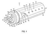
FIG. 1 is a perspective view showing a straight tube type lamp of a first embodiment. -
FIG. 2 is a perspective view showing a section of the straight tube type lamp. -
FIG. 3 is a perspective view showing an inner structure of the straight tube type lamp. -
FIG. 4 is a perspective view showing the whole straight tube type lamp. -
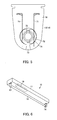
FIG. 5 is a front view of a socket on which the straight tube type lamp is mounted. -
FIG. 6 is a perspective view of a luminaire using the straight tube type lamp. -
FIG. 7 is a wiring diagram of the luminaire. -
FIG. 8 is a perspective view showing a straight tube type lamp of a second embodiment. -
FIG. 9 is a perspective view showing a straight tube type lamp of a third embodiment. - In general, according to one embodiment, a straight tube type lamp includes a light source unit, a straight-tube cover and a cap. At least a part of the straight-tube cover is translucent, and the straight-tube cover contains the light source unit. The cap includes an insulating cap body disposed at an end part of the straight-tube cover, a pair of terminals projecting from an end face of the cap body and an insulating projection. The projection includes a holding part arranged between the pair of terminals, and a projecting part which projects from a tip of the holding part in a direction of arrangement of the pair of terminals and is arranged at a tip side of the pair of terminals.
- The erroneous insertion prevention and fall prevention functions are secured by the holding part and the projecting part of the projection projecting from the cap body, and the deformation of the terminal is expected to be prevented.
- Hereinafter, a first embodiment will be described with reference to
FIG. 1 to FIG. 7 . - As shown in
FIG. 6 , a luminaire 10 includes a longluminaire body 11, a straighttube type lamp 12 arranged in theluminaire body 11,sockets luminaire body 11 so as to face each other and on which both ends of the straighttube type lamp 12 are mounted, and apower supply circuit 15 disposed in theluminaire body 11 and the like. -
FIG. 1 to FIG. 4 show the straighttube type lamp 12. The straighttube type lamp 12 has, for example, a T5 size of 16 mm in tube diameter, and includes a cylindrical straight-tube cover 20, alight source unit 21 contained in the straight-tube cover 20, andcaps tube cover 20. - The straight-
tube cover 20 is made of, for example, synthetic resin, and at least a part of a peripheral wall corresponding to a light irradiation direction is translucent. - The
light source unit 21 includes abase 25 formed to be thin and long in a lamp longitudinal direction and a plurality of light-emitting modules 26 disposed on thebase 25 along the lamp longitudinal direction. - The
base 25 is a thermal radiator formed of a material such as aluminum by extrusion molding. Thebase 25 includes aflat base plate 27, andedge parts 28 are formed at a front side of thebase plate 27 and at both side thereof in the width direction. Theedge parts 28 are provided withgroove parts 29 into which the light-emittingmodule 26 can be inserted from an end part in the lamp longitudinal direction and which hold the inserted light-emitting module 26. A plurality ofgroove parts 30 is formed at the back side of thebase plate 27 along the lamp longitudinal direction. - The light-
emitting module 26 includes asubstrate 31 and a plurality of light-emittingelements 32 mounted on thesubstrate 31 along the lamp longitudinal direction. Thesubstrate 31 is made of a material such as, for example, metal, ceramic or resin, and awiring pattern surface 31a on which a wiring pattern is formed through an insulating layer is provided at the front side thereof. The light-emitting elements 32 are mounted on thewiring pattern surface 31a, and the light-emitting elements 32 are electrically connected to the wiring pattern. The light-emitting elements 32 are semiconductor light-emitting elements such as LED elements or EL elements. In the case of the LED elements, a surface mount type SMD (Surface Mount Device) package is used. Incidentally, a COB (Chip On Board) module in which a plurality of LED elements is mounted on thesubstrate 31 and is sealed with translucent resin containing phosphor may be used as the light-emitting module 26. - A series circuit 33 to which the plurality of light-
emitting elements 32 is connected in series by the wiring pattern is formed on the substrate 31 (seeFIG. 7 ), and a pair of power supply input parts of the series circuit 33 are provided at thecap 22 side of one end. - The
caps caps cap body 34, a substantially T-shaped projection 35 projecting from the outer end face of thecap body 34, and a pair ofterminals 36 projecting from the outer end face of thecap body 34 at both sides of theprojection 35. - The
cap body 34 and theprojection 35 are integrally molded of insulating synthetic resin. The pair ofterminals 36 pass through from the inner end face of thecap body 34 to the outer end face and are combined. - The
cap body 34 includes acylindrical part 37 having a substantially same diameter as the straight-tube cover 20, afitting part 38 projecting from the center area of the inner end face of thecylindrical part 37 and fitted to the inside of the straight-tube cover 20, and abase part 39 projecting from the center area of the outer end face of thecylindrical part 37. - The
cylindrical part 37 is provided with a triangular recessedmark 40 which indicates the direction of the straighttube type lamp 12 corresponding to the light-emitting elements 32 and the direction of light irradiation direction of the straighttube type lamp 12. - A
flat substrate press 41 which is inserted in thegroove part 29 of thebase 25 and regulates the end face position of thesubstrate 31 projects from the inner end face of thefitting part 38. Further, a plurality ofinsertion parts 42 projects therefrom, which is inserted in the plurality ofgroove parts 30 of thebase 25 and is positioned by thebase 25. Ahousing part 43 to house theterminals 36 is opened and formed in the inner end face of thefitting part 38 above thesubstrate press 41. A pair ofinsertion holes 44 through which the pair ofterminals 36 is inserted is formed from thehousing part 43 to the outer end face of thecap body 34. - A
recess part 45 is formed on the peripheral surface of thefitting part 38 along the inner end face of thecylindrical part 37, and aring 46 is fitted in therecess part 45. Thering 46 is made of silicone resin or rubber, for example, has elasticity and intervenes between the end face of the straight-tube cover 20 and thecaps base 25. Thering 46 absorbs the thermal expansion difference in the lamp longitudinal direction between the straight-tube cover 20 and thecaps base 25. - In the
base part 39, theprojection 35 integrally projects, the pair ofterminals 36 is projected from the pair ofinsertion holes 44, and anattachment hole 47 is formed. Thecaps base 25 by screwing ascrew 48 to thegroove part 30 of thebase 25 through theattachment hole 47. - The
projection 35 includes aholding part 51 which projects from the outer end face of thecap body 34 and is arranged between the pair ofterminals 36, and a projectingpart 52 which projects in the direction of arrangement of the pair ofterminals 36 from the tip of theholding part 51 and is arranged at the tip side of the pair ofterminals 36. The projection is formed to be substantially T-shaped. -
Semicircular holding grooves 53 in which the peripheral surface sides of the pair ofterminals 36 facing each other are fitted are formed at both sides of theholding part 51. The projectingpart 52 is provided with a pair ofholding holes 54 in which the tips of the pair ofterminals 36 are fitted. - In the
projection 35, the projectingpart 52 projects more than the pair ofterminals 36 in the direction of arrangement of the pair of theterminals 36, and theholding part 51 and the projectingpart 52 project more than the pair ofterminals 36 in the direction perpendicular to the direction of arrangement of the pair of theterminals 36. Accordingly, the pair ofterminals 36 is arranged inside the outer shape region of theholding part 51 and the projectingpart 52. -
Grooves 55 are formed on one surface and the other surface of theholding part 51 between the pair ofterminals 36 from thecap body 34 to the projectingpart 52. Thegroove 55 on the one surface of theholding part 51 is continuously formed to the outer end face of the cap body 34 (base part 39), and thegroove 55 on the other surface of theholding part 51 is continuous with theattachment hole 47 formed in the outer end face of the cap body 34 (base part 39). - The pair of
terminals 36 is formed by press-molding a conductive metal plate material, and respectively includefixing parts 58,cylindrical pins 59 projecting from one end of thefixing parts 58, andcontact pieces 60 projecting from the other end of thefixing parts 58. - The fixing
parts 58 are curved and formed. The fixingparts 58 of the pair ofterminals 36 are fitted in an insulatingcylindrical fixing member 61, and the pair ofterminals 36 is integrally held in an insulating state from each other. The fixingparts 58 of the pair ofterminals 36 and the fixingmember 61 are housed in thehousing part 43 of thecap body 34. - The
pin 59 is formed into a cylindrical shape. The pin is inserted into theinsertion hole 44 from the inner end face of thecap body 34, and projects from the outer end face of thecap body 34. The base end side of thepin 59 is inserted in theinsertion hole 44 and is held. The tip side projecting from thecap body 34 is fitted in the holdinggroove 53 of the holdingpart 51 and the holdinghole 54 of the projectingpart 52 and is held. - A
contact 62 which contacts thewiring pattern surface 31a of thesubstrate 31 and is electrically connected is formed at the tip of thecontact piece 60. Abent part 63 bent in a direction of separating from thesubstrate 31 is formed at a middle part thereof. Thecontact piece 60 has elasticity in a direction in which thecontact 62 is in press contact with thesubstrate 31. - The pair of
terminals 36 of thecap 22 at one end is electrically connected to the pair of power supply input parts of the series circuit 33 formed on thesubstrate 31. The pair ofterminals 36 at the other end is shorted through afuse 64. Thefuse 64 is mounted on, for example, thesubstrate 31. The pair ofterminals 36 of thecap 23 at the other end contacts thewiring pattern surface 31a and is electrically connected, so that the pair of terminals is shorted through thefuse 64. Incidentally, thefuse 64 may be connected to the pair ofterminals 36 without being mounted on thesubstrate 31. - Incidentally, the straight
tube type lamp 12 is constructed such that the directions of arrangement of the pair ofterminals 36 of thecaps terminals 36 is parallel to thewiring pattern surface 31a. - Besides, the thickness size of the holding
part 51 and the projectingpart 52 and the diameter size of the pair ofterminals 36 are larger than the diameter size of the lamp pin specified for the G5 type cap. Thus, thecaps - Besides, as shown in
FIG. 5 , a rotation mounting system is used for thesockets projection 35 and the pair ofterminals 36 are rotated by 90° around the lamp axis of the straighttube type lamp 12 and are mounted. Thesockets socket body 70, a pair ofterminals 71 arranged in thesocket body 70, and arotator 72 rotatably arranged in thesocket body 70. Aninsertion port 73 in which theprojection 35 and the pair ofterminals 36 are inserted is formed at the tip side of thesocket body 70. Acircular opening 74 in which therotator 72 is rotatably arranged is formed in the front surface of thesocket body 70. The pair ofterminals 71 is arranged at both sides of therotator 72.Insertion grooves 75 in which theprojection 35 and the pair ofterminals 36 are inserted are formed in therotator 72. -
FIG. 7 is a wiring diagram of theluminaire 10. Thepower supply circuit 15 receives power from a commercial AC power supply E and converts into specified DC power, and supplies the converted DC power to thelight source unit 21 of the straighttube type lamp 12 through thesockets - In the
luminaire body 11, ones of the pair ofterminals 71 of both thesockets connection line 76, and the others are electrically connected to a pair offeeders 77 of thepower supply circuit 15. By this, even when thecaps tube type lamp 12 are connected to thesockets power supply circuit 15 can supply power to thelight source unit 21 of the straighttube type lamp 12. - When the straight
tube type lamp 12 constructed as stated above is mounted between thesockets insertion ports 73 of thesockets projections 35 and the pair ofterminals 36 of thecaps tube type lamp 12 to the specified mount position. - When the straight
tube type lamp 12 is rotated to the specified mount position, the pair ofterminals 36 of thecaps terminals 71 of thesockets - In the mount state of the straight
tube type lamp 12, the projectingpart 52 projecting in the direction of arrangement of the pair ofterminals 36 is caught on thesockets tube type lamp 12 or deflection due to its own weight, thecaps tube type lamp 12 are prevented from falling off from thesockets - Besides, the
caps projections 35 and the pair ofterminals 36 are not compatible with the G5 type cap, can not be mounted (inserted) on the socket for the G5 type cap, but can be mounted (inserted) only on thesuitable sockets - Besides, the
power supply circuit 15 converts AC power from the commercial AC power supply E into specified DC power, and supplies the converted DC power to thelight source unit 21 of the straighttube type lamp 12 through thesockets elements 32 of thelight source unit 21 are lit, and the light from the light-emittingelements 32 passes through the straight-tube cover 20 and is irradiated to lighting space. - In the
caps tube type lamp 12 of this embodiment, the insulatingprojection 35, together with the pair of terminals, projects from the end face of thecap body 34. Theprojection 35 includes the holdingpart 51 arranged between the pair ofterminals 36, and the projectingpart 52 which projects from the tip of the holdingpart 51 in the direction of arrangement of the pair ofterminals 36 and is arranged at the tip side of the pair ofterminals 36. By this structure, the rigidity of the pair ofterminals 36 can be increased, and the erroneous insertion prevention and fall prevention functions can be secured not by theterminals 36 but by the holdingpart 51 and the projectingpart 52. Accordingly, theterminals 36 can be prevented from being deformed by load application thereto. - Further, the projecting
part 52 projects more than the pair ofterminals 36 in the direction of arrangement of the pair ofterminals 36, and the holdingpart 51 and the projectingpart 52 project more than the pair ofterminals 36 in the direction perpendicular to the direction of arrangement of the pair ofterminals 36. Thus, the pair ofterminals 36 can be arranged inside the outer shape region of the holdingpart 51 and the projectingpart 52, and can be prevented from being deformed by load application thereto at the time of handling of the straight tube type lamp, at the time of attachment to and detachment from thesockets - Besides, since the
groove 55 is formed in the holdingpart 51 from thecap body 34 to the projectingpart 52, even if the holdingpart 51 is arranged between the pair ofterminals 36, a creeping distance between the pair ofterminals 36 can be secured, and the insulation property can be improved. - Besides, the pair of
terminals 36 passes through thecap body 34 and is connected to thewiring pattern surface 31a of thesubstrate 31. Accordingly, electrical connection can be obtained by assembling thecaps light source unit 21, and thus the assembling property is excellent, and the structure can be simplified. - Besides, the
ring 46 intervening between the straight-tube cover 20 and thecap tube cover 20 in the lamp longitudinal direction due to temperature change. - Besides, since the
cap body 34 and theprojection 35 are integrally formed, the number of parts can be reduced and the assembling property can be improved. - Incidentally, the
projection 35 may be formed separately from thecap body 34, and theprojection 35 may be attached to thecap body 34. - Next, a second embodiment is shown in
FIG. 8 . Incidentally, the same components as those of the first embodiment are denoted by the same reference numerals, and a description about the structure, operation and effect thereof is omitted. - In the straight
tube type lamp 12, thecap 22 at one end is provided with theterminals 36 and is a power supply side, and thecap 23 at the other end is not provided with theterminals 36 and is a non-power supply side. - Although the
cap 22 at the one end of the straighttube type lamp 12 has the same cap structure as that of the first embodiment, thecap 23 at the other end is such that the pair ofterminals 36 is removed from the cap structure of the first embodiment. That is, thecap 23 at the other end includes only thecap body 34 in which theprojection 35 is protrudingly provided. - In the straight
tube type lamp 12 in which thecap 22 at the one end is the power supply side, and thecap 23 at the other end is the non-power supply side, thesame cap body 34 as that of thecap 22 at the one end can be commonly used for thecap 23 at the other end, and the cost of parts can be reduced. - Next, a third embodiment is shown in
FIG. 9 . Incidentally, the same components as those of the first embodiment are denoted by the same reference numerals, and a description about the structure, operation and effect thereof is omitted. - The straight
tube type lamp 12 is such that thecap 22 at one end is provided with theterminals 36 and is a power supply side, and the cap (second cap) 23 at the other end is not provided with theterminals 36 and is a non-power supply side. - Although the
cap 22 at the one end of the straighttube type lamp 12 has the same cap structure as that of the first embodiment, thecap 23 at the other end includes the cap body (second cap body) 34 in which the protrusion (second protrusion) 35 including the holdingpart 51 and the projectingpart 52 is protrudingly provided. - Both side surfaces of the holding
part 51 in a width direction are formed to be arc-shaped. When theprojection 35 is inserted into thesocket 14, or is rotated and operated, the operation can be smoothly performed. - The
insertion hole 44 is not opened in an end face of thecap body 34, and intrusion of insects and dust into the straight-tube cover 20 can be prevented. - In the case of the second and third embodiments, with respect to wiring between the straight
tube type lamp 12 and thepower supply circuit 15, the pair offeeders 77 of thepower supply circuit 15 is connected only to thesocket 13 at the one end, and power is supplied to the straighttube type lamp 12 from thecap 22 connected to thesocket 13 at the one end. - Besides, in the case of the straight
tube type lamp 12 in which thecap 22 at the one end is the power supply side and thecap 23 at the other end is the non-power supply side, colors of therings 46 may be made different from each other, so that thecap 22 at the power supply side and thecap 23 at the non-power supply side are easily differentiated. - While certain embodiments have been described, these embodiments have been presented by way of example only, and are not intended to limit the scope of the inventions. Indeed, the novel embodiments described herein may be embodied in a variety of other forms; furthermore, various omissions, substitutions and changes in the form of the embodiments described herein may be made without departing from the spirit of the inventions. The accompanying claims and their equivalents are intended to cover such forms or modifications as would fall within the scope and spirit of the inventions.
Claims (5)
- A straight tube type lamp (12) comprising:a light source unit (21);a straight-tube cover (20) at least a part of which is translucent and which contains the light source unit (21); anda cap (22) including an insulating cap body (34) disposed at an end part of the straight-tube cover (20), a pair of terminals (36) projecting from an end face of the cap body (34) and an insulating projection (35), wherein the projection (35) includes a holding part (51) arranged between the pair of terminals (36), and a projecting part (52) which projects from a tip of the holding part (51) in a direction of arrangement of the pair of terminals (36) and is arranged at a tip side of the pair of terminals (36).
- The lamp (12) according to claim 1, wherein the projecting part (52) projects more than the pair of terminals (36) in the direction of arrangement of the pair of terminals (36), and the holding part (51) and the projecting part (52) project more than the pair of terminals (36) in a direction perpendicular to the direction of arrangement of the pair of terminals (36).
- The lamp (12) according to claim 1 or 2, wherein the holding part (51) is provided with a groove (55) from the cap body (34) to the projecting part (52).
- The lamp (12) according to any one of claims 1 to 3, wherein
the light source unit (21) includes a substrate (31) provided with a wiring pattern surface (31a) and a light-emitting element (32) mounted on the wiring pattern surface (31a) of the substrate (31), and
the pair of terminals (36) passes through the cap body (34) and is connected to the wiring pattern surface (31a) of the substrate (31). - A luminaire (10) comprising:a socket (13); andthe straight tube type lamp (12) which is according to any one of claims 1 to 4 and is mounted on the socket (13).
Applications Claiming Priority (1)
| Application Number | Priority Date | Filing Date | Title |
|---|---|---|---|
| JP2013177973A JP2015046352A (en) | 2013-08-29 | 2013-08-29 | Straight tube lamp and lighting device |
Publications (1)
| Publication Number | Publication Date |
|---|---|
| EP2843291A1 true EP2843291A1 (en) | 2015-03-04 |
Family
ID=50238197
Family Applications (1)
| Application Number | Title | Priority Date | Filing Date |
|---|---|---|---|
| EP14157883.1A Withdrawn EP2843291A1 (en) | 2013-08-29 | 2014-03-05 | Straight tube type lamp and luminaire |
Country Status (5)
| Country | Link |
|---|---|
| US (1) | US20150062889A1 (en) |
| EP (1) | EP2843291A1 (en) |
| JP (1) | JP2015046352A (en) |
| CN (1) | CN203810108U (en) |
| TW (1) | TW201508205A (en) |
Cited By (3)
| Publication number | Priority date | Publication date | Assignee | Title |
|---|---|---|---|---|
| WO2016146330A1 (en) * | 2015-03-19 | 2016-09-22 | Osram Gmbh | Semiconductor lamp |
| GB2541886A (en) * | 2015-08-31 | 2017-03-08 | Lin Ruei-Hsing | LED device |
| WO2017056110A1 (en) * | 2015-09-29 | 2017-04-06 | Corvi Led Pvt Ltd | Led tubular lamp assembly |
Families Citing this family (13)
| Publication number | Priority date | Publication date | Assignee | Title |
|---|---|---|---|---|
| MX2013010885A (en) * | 2011-03-25 | 2013-12-06 | Koninkl Philips Nv | Luminaire lens assembly having a thermal compensation unit and method thereof. |
| US9920893B2 (en) * | 2014-06-18 | 2018-03-20 | General Led Opco, Llc | Busline LED module |
| US20170336055A1 (en) * | 2014-10-23 | 2017-11-23 | Oy Mtg-Meltron Ltd | Lighting apparatus for hazardous areas |
| JP6690123B2 (en) * | 2015-03-16 | 2020-04-28 | 三菱電機株式会社 | Base for lighting lamp, lighting lamp and lighting device |
| JP6706440B2 (en) * | 2015-07-17 | 2020-06-10 | アイリスオーヤマ株式会社 | Lighting equipment |
| WO2017160883A1 (en) | 2016-03-15 | 2017-09-21 | Energy Focus, Inc. | Lamp and lamp socket having multiple connectors |
| US10236716B2 (en) * | 2016-04-22 | 2019-03-19 | Energy Focus, Inc. | Lamp with battery backup capability |
| US10145516B2 (en) * | 2016-08-30 | 2018-12-04 | Lecconnect, Llc | LED light tube end cap with self-docking driver comm board |
| US10892615B2 (en) | 2017-04-25 | 2021-01-12 | Energy Focus, Inc. | Circuit for mitigating electric shock |
| DE102017131063A1 (en) * | 2017-12-22 | 2019-06-27 | Ledvance Gmbh | LED module with a stabilized leadframe |
| WO2021125473A1 (en) * | 2019-12-19 | 2021-06-24 | 주식회사 필룩스 | Lighting device |
| FR3108707B1 (en) * | 2020-03-26 | 2022-02-25 | Lumila | Elongated light-emitting diode lighting device |
| USD1077318S1 (en) * | 2023-05-16 | 2025-05-27 | JumpLights, Inc. | Light fixture |
Citations (4)
| Publication number | Priority date | Publication date | Assignee | Title |
|---|---|---|---|---|
| EP1562269A1 (en) * | 2004-02-04 | 2005-08-10 | Light Sources, Inc. | Secure lamp base and socket |
| US20080182454A1 (en) * | 2006-02-27 | 2008-07-31 | Light Sources Inc. | Ultraviolet lamp for use in water purifiers |
| US20100019689A1 (en) * | 2006-02-09 | 2010-01-28 | Led Smart, Inc. | Led lighting system |
| EP2216859A1 (en) * | 2009-02-06 | 2010-08-11 | Tyco Electronics Corporation | End cap assembly for a light tube |
-
2013
- 2013-08-29 JP JP2013177973A patent/JP2015046352A/en active Pending
-
2014
- 2014-03-05 EP EP14157883.1A patent/EP2843291A1/en not_active Withdrawn
- 2014-03-07 US US14/200,044 patent/US20150062889A1/en not_active Abandoned
- 2014-03-19 CN CN201420125493.7U patent/CN203810108U/en not_active Expired - Fee Related
- 2014-03-20 TW TW103110397A patent/TW201508205A/en unknown
Patent Citations (4)
| Publication number | Priority date | Publication date | Assignee | Title |
|---|---|---|---|---|
| EP1562269A1 (en) * | 2004-02-04 | 2005-08-10 | Light Sources, Inc. | Secure lamp base and socket |
| US20100019689A1 (en) * | 2006-02-09 | 2010-01-28 | Led Smart, Inc. | Led lighting system |
| US20080182454A1 (en) * | 2006-02-27 | 2008-07-31 | Light Sources Inc. | Ultraviolet lamp for use in water purifiers |
| EP2216859A1 (en) * | 2009-02-06 | 2010-08-11 | Tyco Electronics Corporation | End cap assembly for a light tube |
Cited By (5)
| Publication number | Priority date | Publication date | Assignee | Title |
|---|---|---|---|---|
| WO2016146330A1 (en) * | 2015-03-19 | 2016-09-22 | Osram Gmbh | Semiconductor lamp |
| US10502370B2 (en) | 2015-03-19 | 2019-12-10 | Ledvance Gmbh | Semiconductor lamp |
| GB2541886A (en) * | 2015-08-31 | 2017-03-08 | Lin Ruei-Hsing | LED device |
| GB2541886B (en) * | 2015-08-31 | 2017-10-04 | Lin Ruei-Hsing | LED device |
| WO2017056110A1 (en) * | 2015-09-29 | 2017-04-06 | Corvi Led Pvt Ltd | Led tubular lamp assembly |
Also Published As
| Publication number | Publication date |
|---|---|
| US20150062889A1 (en) | 2015-03-05 |
| TW201508205A (en) | 2015-03-01 |
| JP2015046352A (en) | 2015-03-12 |
| CN203810108U (en) | 2014-09-03 |
Similar Documents
| Publication | Publication Date | Title |
|---|---|---|
| EP2843291A1 (en) | Straight tube type lamp and luminaire | |
| CN101960204B (en) | Integrated LED driver for LED socket | |
| US8157408B2 (en) | Lighting apparatus | |
| US9153882B2 (en) | Connector having a cylindrical section with a contact connected to an electrical wire therein | |
| US20130170233A1 (en) | Lamp device and lighting apparatus | |
| CN203453877U (en) | Lamp device and lighting device | |
| US9599289B2 (en) | Light source and lighting device including the same | |
| CN102483200A (en) | Light source device | |
| CN202598187U (en) | Luminous device, lamp with lamp socket and illuminating appliance | |
| CN205402432U (en) | Lighting device | |
| JP5472635B2 (en) | Straight tube lamp and luminaire | |
| CN204829426U (en) | Lamp device and lighting device | |
| CN103574525A (en) | End cap and method of making same | |
| CN203743939U (en) | Light emitting module, tubular light emitting lamp, and lighting fixture | |
| JP2011228117A (en) | Light emitting diode (led) lamp structure which can exchange light emitting units | |
| US20150109802A1 (en) | Led lighting device | |
| JP5477590B2 (en) | Lamp device and lighting device | |
| KR20090118293A (en) | LED lighting module | |
| US9307589B2 (en) | Illuminant device and lighting module thereof | |
| JP5572073B2 (en) | Lamp socket and lighting device | |
| JP6712167B2 (en) | Lighting equipment | |
| CN110120619B (en) | Lamp holder and lamp holder assembly | |
| US9671070B2 (en) | LED spherical lamp | |
| CN204313013U (en) | Lamp and lighting device | |
| CN207146080U (en) | Lighting device |
Legal Events
| Date | Code | Title | Description |
|---|---|---|---|
| 17P | Request for examination filed |
Effective date: 20140305 |
|
| AK | Designated contracting states |
Kind code of ref document: A1 Designated state(s): AL AT BE BG CH CY CZ DE DK EE ES FI FR GB GR HR HU IE IS IT LI LT LU LV MC MK MT NL NO PL PT RO RS SE SI SK SM TR |
|
| AX | Request for extension of the european patent |
Extension state: BA ME |
|
| PUAI | Public reference made under article 153(3) epc to a published international application that has entered the european phase |
Free format text: ORIGINAL CODE: 0009012 |
|
| STAA | Information on the status of an ep patent application or granted ep patent |
Free format text: STATUS: THE APPLICATION IS DEEMED TO BE WITHDRAWN |
|
| 18D | Application deemed to be withdrawn |
Effective date: 20150905 |