EP2843197A2 - Blade of a rotary flow machine with a radial strip seal - Google Patents
Blade of a rotary flow machine with a radial strip seal Download PDFInfo
- Publication number
- EP2843197A2 EP2843197A2 EP14179109.5A EP14179109A EP2843197A2 EP 2843197 A2 EP2843197 A2 EP 2843197A2 EP 14179109 A EP14179109 A EP 14179109A EP 2843197 A2 EP2843197 A2 EP 2843197A2
- Authority
- EP
- European Patent Office
- Prior art keywords
- slot
- seal
- radially
- blade
- shank
- Prior art date
- Legal status (The legal status is an assumption and is not a legal conclusion. Google has not performed a legal analysis and makes no representation as to the accuracy of the status listed.)
- Granted
Links
- 238000003780 insertion Methods 0.000 claims description 6
- 230000037431 insertion Effects 0.000 claims description 6
- 238000001816 cooling Methods 0.000 description 9
- 238000007789 sealing Methods 0.000 description 9
- 239000007789 gas Substances 0.000 description 7
- 238000009434 installation Methods 0.000 description 3
- 239000002184 metal Substances 0.000 description 2
- 230000007704 transition Effects 0.000 description 2
- 230000006978 adaptation Effects 0.000 description 1
- 230000000295 complement effect Effects 0.000 description 1
- 230000001419 dependent effect Effects 0.000 description 1
- 230000003467 diminishing effect Effects 0.000 description 1
- 230000000694 effects Effects 0.000 description 1
- 239000012530 fluid Substances 0.000 description 1
- 239000011888 foil Substances 0.000 description 1
- 239000003779 heat-resistant material Substances 0.000 description 1
- 230000001771 impaired effect Effects 0.000 description 1
- 238000011144 upstream manufacturing Methods 0.000 description 1
Images


Classifications
-
- F—MECHANICAL ENGINEERING; LIGHTING; HEATING; WEAPONS; BLASTING
- F01—MACHINES OR ENGINES IN GENERAL; ENGINE PLANTS IN GENERAL; STEAM ENGINES
- F01D—NON-POSITIVE DISPLACEMENT MACHINES OR ENGINES, e.g. STEAM TURBINES
- F01D11/00—Preventing or minimising internal leakage of working-fluid, e.g. between stages
- F01D11/005—Sealing means between non relatively rotating elements
- F01D11/006—Sealing the gap between rotor blades or blades and rotor
-
- F—MECHANICAL ENGINEERING; LIGHTING; HEATING; WEAPONS; BLASTING
- F01—MACHINES OR ENGINES IN GENERAL; ENGINE PLANTS IN GENERAL; STEAM ENGINES
- F01D—NON-POSITIVE DISPLACEMENT MACHINES OR ENGINES, e.g. STEAM TURBINES
- F01D11/00—Preventing or minimising internal leakage of working-fluid, e.g. between stages
- F01D11/005—Sealing means between non relatively rotating elements
-
- F—MECHANICAL ENGINEERING; LIGHTING; HEATING; WEAPONS; BLASTING
- F01—MACHINES OR ENGINES IN GENERAL; ENGINE PLANTS IN GENERAL; STEAM ENGINES
- F01D—NON-POSITIVE DISPLACEMENT MACHINES OR ENGINES, e.g. STEAM TURBINES
- F01D5/00—Blades; Blade-carrying members; Heating, heat-insulating, cooling or antivibration means on the blades or the members
- F01D5/30—Fixing blades to rotors; Blade roots ; Blade spacers
-
- F—MECHANICAL ENGINEERING; LIGHTING; HEATING; WEAPONS; BLASTING
- F05—INDEXING SCHEMES RELATING TO ENGINES OR PUMPS IN VARIOUS SUBCLASSES OF CLASSES F01-F04
- F05D—INDEXING SCHEME FOR ASPECTS RELATING TO NON-POSITIVE-DISPLACEMENT MACHINES OR ENGINES, GAS-TURBINES OR JET-PROPULSION PLANTS
- F05D2240/00—Components
- F05D2240/55—Seals
- F05D2240/57—Leaf seals
-
- F—MECHANICAL ENGINEERING; LIGHTING; HEATING; WEAPONS; BLASTING
- F05—INDEXING SCHEMES RELATING TO ENGINES OR PUMPS IN VARIOUS SUBCLASSES OF CLASSES F01-F04
- F05D—INDEXING SCHEME FOR ASPECTS RELATING TO NON-POSITIVE-DISPLACEMENT MACHINES OR ENGINES, GAS-TURBINES OR JET-PROPULSION PLANTS
- F05D2240/00—Components
- F05D2240/80—Platforms for stationary or moving blades
- F05D2240/81—Cooled platforms
-
- F—MECHANICAL ENGINEERING; LIGHTING; HEATING; WEAPONS; BLASTING
- F05—INDEXING SCHEMES RELATING TO ENGINES OR PUMPS IN VARIOUS SUBCLASSES OF CLASSES F01-F04
- F05D—INDEXING SCHEME FOR ASPECTS RELATING TO NON-POSITIVE-DISPLACEMENT MACHINES OR ENGINES, GAS-TURBINES OR JET-PROPULSION PLANTS
- F05D2250/00—Geometry
- F05D2250/70—Shape
- F05D2250/75—Shape given by its similarity to a letter, e.g. T-shaped
-
- F—MECHANICAL ENGINEERING; LIGHTING; HEATING; WEAPONS; BLASTING
- F05—INDEXING SCHEMES RELATING TO ENGINES OR PUMPS IN VARIOUS SUBCLASSES OF CLASSES F01-F04
- F05D—INDEXING SCHEME FOR ASPECTS RELATING TO NON-POSITIVE-DISPLACEMENT MACHINES OR ENGINES, GAS-TURBINES OR JET-PROPULSION PLANTS
- F05D2260/00—Function
- F05D2260/30—Retaining components in desired mutual position
Definitions
- the invention concerns a blade of a rotating flow machine.
- the blade comprising, an airfoil having a suction surface and a pressure surface joined together along a trailing and a leading edge, a radially outwardly extending airfoil tip and a radially inward extending end joining an inner platform connecting the airfoil to a shank located at a radial end of the airfoil.
- the shank includes at least one shank pocket whose radially outwardly extending point is encircled by a portion of the platform that extends axially.
- At least one radially extending rim extends from the trailing edge side of the shank and has a radially orientated slot for receiving a seal.
- a mount extends radially inwardly from the shank pocket.
- Blades of a rotary flow machine such as a compressor unit or a turbine stage of a gas turbine arrangement, are typically circumferentially arranged on a plurality of axially ordered rotor wheels.
- the platforms of each blade delimit the working channel of the rotary flow machine, which in case of a turbine stage is the hot gas channel where hot gases emerging from an upstream combustor expand and convert kinetic energy into rotational mechanical energy.
- Highly-compressed air is typically extracted from the compressor unit of an axial turbine for the purpose of cooling turbine components, particularly those in the hot gas path downstream of the combustor.
- the cooling air is required to maintain the temperature of the turbine components at an acceptable level for operation, but comes at a cost to overall turbine efficiency and output. Therefore it is important to reduce any cooling flow leakage out of the turbine components.
- the area between adjacent blades in a common blade row of a rotor wheel radially inward of the platforms of each blade is typically referred to as a shank pocket.
- cavities between rotating blades and axially adjacent stationary components axially forward and aft of each shank pocket operate at different pressures to enable a natural fluid flow from the higher pressure cavity to the lower pressure cavity through the gaps which are necessary for movement and expansion between adjacent rotating blades.
- Each of these gaps has a large leakage path for cooling flow to escape from the shank region of the blade.
- the cooling efficiency can also be impaired by ingress of hot gas from the hot gas path into the shank region.
- Document EP 2 584 151 A2 discloses a sealing system for a turbine rotor blade having at least one shank pocket encircled radially outwardly by an axially extending portion of the platform. At least one radially directed rim extending from the trailing edge side of the shank has a radially orientated first slot for receiving a seal.
- the seal may be a strip seal comprising an arm portion and a hook portion wherein the arm and hook portions are shaped to mate with the slot such that the slot restrains the movement of the seal, wherein size of the seal substantially prevents a cooling flow from leaking through the shank pocket.
- the strip like seal bordering the shank portion of a first and a second blade that has a width that substantially prevents a cooling flow from leaking through the shank pocket.
- a further sealing arrangement for a turbine blade is disclosed in the document US 2012/0237352 A .
- the sealing arrangement comprises two circumferentially adjacent arranged blades on a rotor wheel having an enclosed essentially radially oriented groove.
- the groove has at least one radial seal pin having an essentially uniformly round cross-section.
- a further objective is to simplify the assembling work required to introduce a seal in the slot between two neighboring shanks shall.
- a blade of a rotary flow machine comprises an air foil having a suction surface and a pressure surface joined together along a trailing and a leading edges, a radially outward directed airfoil tip and a radially inward directed end joining an inner platform that connects the airfoil to a shank at a radial end of the airfoil and further has at least one shank pocket encircled in the radially outward direction by an axially extending portion of the platform.
- At least one radially extending rim that extends from the trailing edge side of the shank has a radially orientated slot for receiving a seal and a mount that extends radially inwardly from said shank pocket.
- the blade is characterized by the shank has an aperture on the shank surface oriented in an axial direction.
- the axially facing surface of the shank is freely accessible even in the mounted state, i.e. all blades are circumferentially assembled in the rotor wheel.
- the inventive idea establishes a basis for the possibility to insert a seal after at least two neighboring blades, preferably all blades, are assembled onto a rotor wheel by inserting mounts of each blade into correspondingly shaped recesses in the rotor wheel.
- the shank of each blade has a second slot having an aperture on an opposite surface to the rim.
- the second slot and aperture preferably are of the same size and shape as the slot and aperture in the at least one radially directed rim.
- the shanks of two neighboring blades adjoin each other such that the slot and aperture in the at least one rim of one of the two adjoining blades aligns radially and axially with the second slot and aperture of the other blade.
- the aligned slots form a cavity with a radially oriented longitudinal extension that preferably has a rectangular cross-section having a circumferential orientation rectangular side that defines the width of the rectangular cavity. In this way both apertures complement each other so as to form a common access opening through which a strip-like seal may be received into the rectangular cavity after the blades are assembled.
- the strip-like seal received in the rectangular cavity is made of a heat resistant material, most preferable having a length and width which corresponds to the radial extension and width of the rectangular cavity respectively.
- the shape and size of the seal corresponds to individual arrangements of the slots described in more detail in the following illustrated embodiments.
- the aperture of the slot in the shank and the associated position of the access opening is radially arranged between the platform and the mount of the blade.
- the aperture of the essentially radially oriented slots is arranged at the radially outer end of the slot, that is, the aperture is located radially close to the platform of the blade. This location makes it possible to easily insert the strip-like seal through the access opening of the already assembled blades.
- the slot in the at least one radially directed rim is a grooved-shaped recess having a radially outward end bordered axially by a nose-like contour separating the radially outward end and the slot from the aperture.
- a further embodiment enables an easier way of loading the slot with a seal during blade assembly. Furthermore, this embodiment has accurate self-alignment of the seal within the slot bordered by the shanks of two neighboring blades.
- a blade of a rotary flow machine comprises an airfoil having a suction and a pressure surfaces joining together along a trailing and a leading edge, a radially outward directed airfoil tip and a radially inward directed end joining an inner platform that connects the airfoil to a shank radially opposite airfoil having at least one shank pocket encircled radially outwardly by an axially extending portion of the platform and by at least one radially extending rim of the trailing edge side of the shank having a radially orientated first slot suitable for receiving a seal and a mount extending radially inward from the shank pocket having a second slot arranged on an opposite surface to the rim configured such that when assembling two blades in the circumferential direction of the rotary flow machine both slots form a common gap in which a seal is receivable prior to the assembly the two blades.
- the received seal is preferably sized to substantially prevent a leakage flow through the shank pocket.
- the blade is characterized in that one of the two slots has a groove-shaped recess with a width and a depth adapted to a width of a strip-like seal such that a hypotenuse of the width and depth of the groove-shaped recess is of the same size or greater than the width of the strip-like seal.
- the width of the strip-like seal on the other hand is greater or equal 50% of the length of the hypotenuse, preferably equal or greater than 70% of the length of the hypotenuse.
- the strip-like seal Due to the geometry and size adaptation between the groove-shaped recess and the strip-like seal it is possible to insert the strip-like seal completely into the groove-shaped recess before assembling the two adjacent blades in circumferentially direction on a rotor wheel. In addition, because the strip-like seal resides completely inside the groove-shaped recess, it is possible to seamless join the two adjacent blades in circumferential direction. In order to ensure that the strip-like seal, which is received along the hypotenuse of the recess during assembly, performs the additional function of an axial facing cover for the gap between the shanks of the two adjacent blades, a tool is necessary to slip the strip-like seal from the starting position along the hypotenuse into the axial sealing position.
- the grooved-shaped recess has along its width a wedge-like contour with a flank portion inclined relative to the axial direction so that one side edge of the strip like seal can be slid along the flank while the strip-like seal is rotating around its length extension into the axial direction so as to seal the gap between the shanks of two adjacent blades to prevent a leakage flow through the shank pocket.
- the flank of the wedge-like contour is located adjacent to a first limiting wall of the groove-shaped recess while the wedge-like contour limits a first gap with a second limiting wall located opposite to the first limiting wall.
- the second slot has at least a second gap facing the first gap so that axial ends of the strip-like seal projects into both gaps simultaneously.
- a further preferred embodiment has a helical contour along the radial direction of one limiting wall inside the grooved-shaped recess such that the strip-like seal, which initially takes the position along the hypotenuse of the grooved-shaped recess during assembling the blades, will turn itself without any tooling by means of centrifugal forces applied during the first commissioning.
- the helical contour is provided only in a radial outward region along the grooved-shaped recess. Further details of the invention can be derived from the following disclosure describing preferred embodiments shown in the figures.
- Fig. 1 illustrates a first embodiment of a blade 1 of, for example, a moving low pressure turbine blade for a gas turbine arrangement.
- Fig. 1 a shows a side view in the circumferential direction c of rotary flow machine (not shown) of the radially inner section of the blade 1.
- the axes shown in fig. 1 a mark the axial direction a, the radial direction r and the circumferential direction c of the rotary flow machine. The further description makes reference to the axes defined in each illustration.
- the blade 1 comprises an airfoil 2 having a suction surface 3 and a pressure surface (not shown) joined together along a leading edge 4 and trailing edge 5.
- the radially inwardly extending end of the airfoil 2 joins an inner platform 6 connecting the airfoil 2 to a shank 7 at a radial end of airfoil 2.
- the shank 7 has at least one shank pocket 8 which is defined as an area recessed in the shank 7 that is radially encircled by an axially a portion of the platform 6 and by at least one radially directed rim 9 that extends from the trailing edge 5 side of the shank 7.
- the shank 7 has a slot 10, as shown in fig.
- the blade 1 further comprises a mount 12 extending radially inward from the shank pocket 8 for fixing the blade 1 into a counter-contoured recess in a rotor-wheel of the rotary flow machine.
- Fig. 1c is an enlarged view of the section of fig. 1 a enclosed by a dashed line.
- Fig. 1d shows an enlarged view of the section fig. 1c enclosed by a dashed line
- Fig. 1c shows a slot 10 configured as a wedge-like grooved-shaped recess with an axial recess width becoming narrower towards the radially inward direction.
- the slot 20 has an aperture 13 which merges at a shank surface 14 oriented to face an axial direction a.
- the aperture 13 is connected to the slot 10 such that a seal 11, preferably in form of a rectangular strip-like metal seal, as shown in fig. 1b , can be inserted through the aperture 13 into the slot 10.
- the length of the seal 11 corresponds to the length of the slot 10.
- the slot 10 has a longitudinal axis 15 which is incline to the radial direction r by an angle ⁇ in the range of 100° ⁇ ⁇ ⁇ 170° preferably 130° ⁇ ⁇ ⁇ 150°. Due to the inclination of the slot 10 the seal 11, which is inserted into the slot 10, is pressed against the radial outward surface 16 of the slot 10 by centrifugal forces 17 acting onto the seal 11 during rotation around an axis of rotation of the rotary flow machine. Due to the effect of centrifugal forces 17 onto the seal 11 the seal 11 is pressed in a gastight manner against the surface 16 countering pressure in the shank pocket 8 acting onto the seal 11.
- the slot has at its radially outward end a nose-like contour 18 which separates the radially outward end 19 of the slot 10 from the aperture 13 in the axial direction.
- a nose-like contour 18 which separates the radially outward end 19 of the slot 10 from the aperture 13 in the axial direction.
- the blade 1 has an opposed side in circumferential direction c to the represented side shown in fig. 1 a to d.
- the shank 7 has a second slot with an aperture which is a mirror image of the slot and aperture in the rim 9, so that when assembling two blades in circumferential direction c of the rotary flow machine both slots enclose a common gap and form a common aperture through which the seal 11 can be received wherein the seal is sized to prevent a leakage flow through the shank pocket 8.
- Fig. 1b shows an inserted seal into the slot 10.
- the circumferentially c protruding part of the seal 11 extends over the slot 10 into the second slot of a blade assembled adjacent to the blade shown in fig 1 b.
- Fig. 2a is a perspective view of the shank portion 7 of a blade that is comparable to the embodiment shown in fig. 1 c.
- Slot 10 has a wedge-like grooved-shaped recess that narrower in the radially inward direction r.
- the slot 10 is connected to an aperture 13 in the region of the radial outward directed end of the slot 10.
- the longitudinal axis 15 of the slot 10 is inclined to the radial direction r by an angle ⁇ greater than in case of fig. 1 c.
- the seal 11 which is a metal strip, has at its radially inner end an overfold feature 20 that is compressed at the radially inner end of the slot 10 such that the seal 11 is forced against the surface 16. It is further expected that after the rotary flow machines starts up, due to the centrifugal forces 17, the seal 11 will move to the radially outer end 19, marked by a ring in fig. 2b .
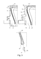
- Fig. 3a to c show a third preferred embodiment in which a radial seal is introduced into a slot 10 formed after blades are assembled on a rotary wheel.
- the slot 10 has a contoured grooved-shaped recess adapted for a clasped-like seal 11.
- the slot 10 comprises a bent strip having two close together strip ends 11', 11" at the radially outward end 19 of the slot 10 and a curved bent section 21 at the radially inward extending end of the slot 10.
- the curved bent section 21 of the seal 11 pushes the clasped-like seal 11 against the inner axial surfaces of the contoured grooved-shaped recess of the slot 10.
- the contoured grooved-shaped recess further has a longitudinal axis 15 which is slightly inclined to the radial direction r so that the upper strip end 11 ", which does not fit tightly at the radially outward surface 16 of the slot 10 as can be seen in fig. 3a , can move into a sealing location shown in fig. 3b as a result of centrifugal forces 17 generated during operation of the rotary flow machine.
- a nose-like contour 18 prevents the strip end 11" moving through the aperture 13 when the rotary flow machine is in stand still mode.
- Fig. 4a to d shows a fourth embodiment of a blade having a radially slot with an aperture formed after blade assembled in a rotary wheel for receiving a seal.
- the section of the shank 7 shown in fig. 4a has a rim 9 which is very small in axial direction and a slot 10 that forms an essentially rectangular grooved recess having a longitudinal axis 15 that is aligned radially without any inclination towards the radial direction r.
- the slot 10 has at its radially outer end an introduction slot 22 connecting the aperture 13 with the slot 10.
- Fig. 4a, b show an embodiment of a rectangular slot 1 that is suitable for the receiving a specially designed seal arrangement shown in fig. 4c and d.
- the specially designed 11 consists of a multiple strip design that a smaller groove angle ⁇ of insertion of the seal through the aperture 13 into the slot 10.
- a preferred multiple strip design shown in fig. 4c has three strip-like seals 11.1, 11.2, 11.3 spot welded together at one common end so that the three strip-like seals form a fan-shaped as shown in fig. 4c .
- one of the three strip-like seals has a greater thickness than the two others, for example a first strip-like seal 11.3 has a thickness of 0,5 mm while the other two 11.1, 11.2 have a thickness of 0,2 mm.
- a thicker strip seal has the advantage of avoid buckling while a thinner strip has increased resilience to plastic deformation when bend during assembly.
- Fig. 4d shows another embodiment of a strip-like seal 11 also having three strip-like seals 11.1, 11.2, 11.3 joined at a common end so that the strip-like seals form a fan-shaped. As shown in fig. 4b one of the strip-like seals 11.1 extends to form a lip 24 for locating the seal arrangement safely in the slot 10.
- the blades shown in the fig. 1 to 4 commonly has an aperture 13 formed after blade assembly through which a strip-like seal or a multi strip design is receivable into a freely accessible surface oriented to face in an axial direction a of the rotary flow machine.
- the blades shown in the f figures 5 and 6 have a slot that extends in the radial direction. The slot is configured to enable the insertion of a seal during assembly work without hindering or impeding the assembly work.
- Fig. 5a shows a perspective view of a blade 1 without an airfoil that would otherwise extend radially beyond the platform 6 from where cooling openings 25 are arranged.
- the shank pocket 8 of the blade 1 is radially encircled by both a portion of the platform 6 that extends axially and by at least one radially directed rim 9 extending from the trailing edge side of the shank 7.
- the rim 9 includes a radially oriented slot 10 for inserting a seal.
- the slot 10 does not have an access aperture for insertion the seal into the slot. Instead, the slot 10 is completely embedded into the rim 9 while having a single circumferentially oriented c opening on one side.
- Figs. 5 b1 to b3 show a cross-section of the slot 10.
- the illustrated upper cross-section shows a slot 10 in the rim 9 of a first blade 1.1 that borders a gap 26 formed in the circumferential direction c by a second blade 1.2 that is arranged adjacent to the first blade 1.1 in the circumferential direction of a rotary wheel (not shown).
- the strip-like seal 11 has a rectangular cross-section having a seal width ws equal or less than the length of the hypotenuse h but equal or greater than 50% but preferably equal or greater than 70% of the length of the hypotenuse h.
- slot 10 has along its width, i.e. in an axial direction, a wedge-like contour 27 with a flank 28 inclined relative to the axial direction a.
- the flank 28 is located adjacent to a first limiting wall 29 of the slot 10.
- the wedge-like contour 27 further limits a first gap 30 with a second limiting wall 31 located facing, in the axial direction, the first limiting wall 29 of the slot.
- the second blade 1.2 as it is arranged circumferentially to the first blade in the assembled configuration, it has a second gap 32 that faces the first gap 30.
- a tool is necessary to slide an end of the strip-like seal 11 along the flank 28 in axial direction whereby the sliding causes the other end of the strip-like seal 11 to enters the second gap 32 of the second blade 1.2.
- the strip-like seal 11 has to be pushed using axial force to move from the position P1 shown in fig. 5 b2 to position P2, i.e. so that the strip-like seal 11 is axially inside the first and second gap 30, 32 of the first and second blade 1.1, 1.2.
- Fig. 6a, b shows an alternative embodiment of a blade having a radially directed slot 10 having a cross-section that enable the movement of the strip-like seal into the slot 10 after positioning the strip-like seal 10 along the hypotenuse h of the cross-section of the slot.
- the slot 10 is extends radially r and has a radially inward end having a triangle cross-section that has a depth d, a width w and a hypotenuse h.
- the slot 10 further has a radially outward end having a cross-section in which the hypotenuse h forms a convex contour 33. There is a transition along the radial height of the slot 10 from a straight hypotenuse h at one end of the slot 10 to a convex contoured 33 hypotenuse h resulting in a surface of the slot 10 forming a helical contour 34.
- Fig. 6a shows the strip-like seal 11 located in the slot 10 before the assembly of an adjoining blade into the rotary wheel in circumferential direction.
- Fig. 6b shows the location of strip-like seal 11 in its axial sealing position. The transition from the seal location shown in fig. 6a and the seal location shown in fig.
Landscapes
- Engineering & Computer Science (AREA)
- Mechanical Engineering (AREA)
- General Engineering & Computer Science (AREA)
- Turbine Rotor Nozzle Sealing (AREA)
- Structures Of Non-Positive Displacement Pumps (AREA)
Abstract
an airfoil (2) having a suction surface (3) and a pressure surface joining each other along a trailing and a leading edge (4, 5), a radially outward directed airfoil tip and a radially inward directed end joining an inner platform (6) connecting the airfoil to a shank (7) at a radial end of the airfoil and providing, at least one shank pocket (8) radially encircled by an axially extending portion of the platform and at least one radially extending rim (9) that extends from the trailing edge side of the shank and has an essentially radially orientated first slot (10) for receiving a seal (11), and a mount (12) extending radially inwardly from said shank pocket. Said first slot has a first aperture (13) on a shank surface orientated in an axial direction.
Description
- The invention concerns a blade of a rotating flow machine. The blade comprising, an airfoil having a suction surface and a pressure surface joined together along a trailing and a leading edge, a radially outwardly extending airfoil tip and a radially inward extending end joining an inner platform connecting the airfoil to a shank located at a radial end of the airfoil. The shank includes at least one shank pocket whose radially outwardly extending point is encircled by a portion of the platform that extends axially. At least one radially extending rim extends from the trailing edge side of the shank and has a radially orientated slot for receiving a seal. A mount extends radially inwardly from the shank pocket.
- Blades of a rotary flow machine, such as a compressor unit or a turbine stage of a gas turbine arrangement, are typically circumferentially arranged on a plurality of axially ordered rotor wheels. The platforms of each blade delimit the working channel of the rotary flow machine, which in case of a turbine stage is the hot gas channel where hot gases emerging from an upstream combustor expand and convert kinetic energy into rotational mechanical energy. Highly-compressed air is typically extracted from the compressor unit of an axial turbine for the purpose of cooling turbine components, particularly those in the hot gas path downstream of the combustor. The cooling air is required to maintain the temperature of the turbine components at an acceptable level for operation, but comes at a cost to overall turbine efficiency and output. Therefore it is important to reduce any cooling flow leakage out of the turbine components.
- The area between adjacent blades in a common blade row of a rotor wheel radially inward of the platforms of each blade is typically referred to as a shank pocket. Typically, cavities between rotating blades and axially adjacent stationary components axially forward and aft of each shank pocket operate at different pressures to enable a natural fluid flow from the higher pressure cavity to the lower pressure cavity through the gaps which are necessary for movement and expansion between adjacent rotating blades. Each of these gaps has a large leakage path for cooling flow to escape from the shank region of the blade. The cooling efficiency can also be impaired by ingress of hot gas from the hot gas path into the shank region.
-
Document EP 2 584 151 A2 discloses a sealing system for a turbine rotor blade having at least one shank pocket encircled radially outwardly by an axially extending portion of the platform. At least one radially directed rim extending from the trailing edge side of the shank has a radially orientated first slot for receiving a seal. The seal may be a strip seal comprising an arm portion and a hook portion wherein the arm and hook portions are shaped to mate with the slot such that the slot restrains the movement of the seal, wherein size of the seal substantially prevents a cooling flow from leaking through the shank pocket. Further, it is disclosed that the strip like seal bordering the shank portion of a first and a second blade that has a width that substantially prevents a cooling flow from leaking through the shank pocket. - A further sealing arrangement for a turbine blade is disclosed in the document
US 2012/0237352 A . The sealing arrangement comprises two circumferentially adjacent arranged blades on a rotor wheel having an enclosed essentially radially oriented groove. The groove has at least one radial seal pin having an essentially uniformly round cross-section. - It is an object of the invention to provide an enhanced seal arrangement for constricting a leakage flow through a leakage gap between shanks of two adjacent circumferentially arranged blades of a rotary flow machine. A further objective is to simplify the assembling work required to introduce a seal in the slot between two neighboring shanks shall.
- The objectives are achieved by the sum of the features in
independent claims - Inventively, a blade of a rotary flow machine comprises an air foil having a suction surface and a pressure surface joined together along a trailing and a leading edges, a radially outward directed airfoil tip and a radially inward directed end joining an inner platform that connects the airfoil to a shank at a radial end of the airfoil and further has at least one shank pocket encircled in the radially outward direction by an axially extending portion of the platform. At least one radially extending rim that extends from the trailing edge side of the shank has a radially orientated slot for receiving a seal and a mount that extends radially inwardly from said shank pocket. The blade is characterized by the shank has an aperture on the shank surface oriented in an axial direction.
- The axially facing surface of the shank is freely accessible even in the mounted state, i.e. all blades are circumferentially assembled in the rotor wheel. The inventive idea establishes a basis for the possibility to insert a seal after at least two neighboring blades, preferably all blades, are assembled onto a rotor wheel by inserting mounts of each blade into correspondingly shaped recesses in the rotor wheel.
- The subsequent introduction of the seals into the slots after complete installation of all blades simplifies installation and reduces installation time associated with the assembling work of a rotary flow machine.
- In a preferred embodiment, the shank of each blade has a second slot having an aperture on an opposite surface to the rim. The second slot and aperture preferably are of the same size and shape as the slot and aperture in the at least one radially directed rim. In an assembled state, the shanks of two neighboring blades adjoin each other such that the slot and aperture in the at least one rim of one of the two adjoining blades aligns radially and axially with the second slot and aperture of the other blade. The aligned slots form a cavity with a radially oriented longitudinal extension that preferably has a rectangular cross-section having a circumferential orientation rectangular side that defines the width of the rectangular cavity. In this way both apertures complement each other so as to form a common access opening through which a strip-like seal may be received into the rectangular cavity after the blades are assembled.
- Preferably, the strip-like seal received in the rectangular cavity is made of a heat resistant material, most preferable having a length and width which corresponds to the radial extension and width of the rectangular cavity respectively. In other aspects, the shape and size of the seal corresponds to individual arrangements of the slots described in more detail in the following illustrated embodiments.
- In all cases the aperture of the slot in the shank and the associated position of the access opening is radially arranged between the platform and the mount of the blade. Preferably, the aperture of the essentially radially oriented slots is arranged at the radially outer end of the slot, that is, the aperture is located radially close to the platform of the blade. This location makes it possible to easily insert the strip-like seal through the access opening of the already assembled blades.
- After a seal is introduced into the rectangular cavity precaution must be taken to avoid the strip-like seal escaping through the access opening due to operational centrifugal and axial forces. To overcome this problem, in a preferred embodiment, the slot in the at least one radially directed rim is a grooved-shaped recess having a radially outward end bordered axially by a nose-like contour separating the radially outward end and the slot from the aperture.
- The described new design for a radial sealing slot in a shank of a blade enables the insertion of a seal strip after assembly of blades around a rotor wheel. With reference to the accompanying drawings several different embodiments for realizing the slot and the strip seal are described.
- An alternative inventive idea for inserting a seal in an essentially radially directed slot in the shank of a blade for reducing or diminishing leakage flow through a gap between the shanks of two adjacent blades to be assembled in one circumferentially row of a rotary wheel will now be described.
- In contrast to the previously discussed seal arrangement which allows insertion of strip-like seals after a complete assembly of blade on a rotary wheel a further embodiment enables an easier way of loading the slot with a seal during blade assembly. Furthermore, this embodiment has accurate self-alignment of the seal within the slot bordered by the shanks of two neighboring blades.
- In a known arrangement, a blade of a rotary flow machine comprises an airfoil having a suction and a pressure surfaces joining together along a trailing and a leading edge, a radially outward directed airfoil tip and a radially inward directed end joining an inner platform that connects the airfoil to a shank radially opposite airfoil having at least one shank pocket encircled radially outwardly by an axially extending portion of the platform and by at least one radially extending rim of the trailing edge side of the shank having a radially orientated first slot suitable for receiving a seal and a mount extending radially inward from the shank pocket having a second slot arranged on an opposite surface to the rim configured such that when assembling two blades in the circumferential direction of the rotary flow machine both slots form a common gap in which a seal is receivable prior to the assembly the two blades. The received seal is preferably sized to substantially prevent a leakage flow through the shank pocket. The blade is characterized in that one of the two slots has a groove-shaped recess with a width and a depth adapted to a width of a strip-like seal such that a hypotenuse of the width and depth of the groove-shaped recess is of the same size or greater than the width of the strip-like seal. The width of the strip-like seal on the other hand is greater or equal 50% of the length of the hypotenuse, preferably equal or greater than 70% of the length of the hypotenuse.
- Due to the geometry and size adaptation between the groove-shaped recess and the strip-like seal it is possible to insert the strip-like seal completely into the groove-shaped recess before assembling the two adjacent blades in circumferentially direction on a rotor wheel. In addition, because the strip-like seal resides completely inside the groove-shaped recess, it is possible to seamless join the two adjacent blades in circumferential direction. In order to ensure that the strip-like seal, which is received along the hypotenuse of the recess during assembly, performs the additional function of an axial facing cover for the gap between the shanks of the two adjacent blades, a tool is necessary to slip the strip-like seal from the starting position along the hypotenuse into the axial sealing position.
- To facility the slipping and rotating motion of the strip-like seal from the position along the hypotenuse to the end position the grooved-shaped recess has along its width a wedge-like contour with a flank portion inclined relative to the axial direction so that one side edge of the strip like seal can be slid along the flank while the strip-like seal is rotating around its length extension into the axial direction so as to seal the gap between the shanks of two adjacent blades to prevent a leakage flow through the shank pocket.
- The flank of the wedge-like contour is located adjacent to a first limiting wall of the groove-shaped recess while the wedge-like contour limits a first gap with a second limiting wall located opposite to the first limiting wall. In an assembled configuration of the two blades in circumferentially direction the second slot has at least a second gap facing the first gap so that axial ends of the strip-like seal projects into both gaps simultaneously.
- A further preferred embodiment has a helical contour along the radial direction of one limiting wall inside the grooved-shaped recess such that the strip-like seal, which initially takes the position along the hypotenuse of the grooved-shaped recess during assembling the blades, will turn itself without any tooling by means of centrifugal forces applied during the first commissioning. As will be described in more detail with a reference to the figures, the helical contour is provided only in a radial outward region along the grooved-shaped recess. Further details of the invention can be derived from the following disclosure describing preferred embodiments shown in the figures.
- The invention shall now be explained in more detail based on exemplary embodiments in conjunction with the drawing. In the drawing
- Fig. 1a to d
- first embodiment of an inventive blade according to a first inventive aspect,
- Fig. 2a to c
- second embodiment of an inventive blade according to the first inventive aspect,
- Fig. 3a to c
- first embodiment of an inventive blade according to the first inventive aspect,
- Fig. 4
- fourth embodiment of an inventive blade according to the first inventive aspect,
- Fig. 5
- first embodiment of an inventive blade concerning to the second inventive aspect, and
- Fig. 6
- second embodiment of an inventive blade concerning to the second inventive aspect.
-
Fig. 1 illustrates a first embodiment of ablade 1 of, for example, a moving low pressure turbine blade for a gas turbine arrangement.Fig. 1 a shows a side view in the circumferential direction c of rotary flow machine (not shown) of the radially inner section of theblade 1. The axes shown infig. 1 a mark the axial direction a, the radial direction r and the circumferential direction c of the rotary flow machine. The further description makes reference to the axes defined in each illustration. - The
blade 1 comprises anairfoil 2 having asuction surface 3 and a pressure surface (not shown) joined together along a leading edge 4 and trailing edge 5. The radially inwardly extending end of theairfoil 2 joins aninner platform 6 connecting theairfoil 2 to ashank 7 at a radial end ofairfoil 2. Theshank 7 has at least oneshank pocket 8 which is defined as an area recessed in theshank 7 that is radially encircled by an axially a portion of theplatform 6 and by at least one radially directedrim 9 that extends from the trailing edge 5 side of theshank 7. Theshank 7 has aslot 10, as shown infig. 1b , orientated radially r for receiving aseal 11 essentially in the axial direction a. Theblade 1 further comprises amount 12 extending radially inward from theshank pocket 8 for fixing theblade 1 into a counter-contoured recess in a rotor-wheel of the rotary flow machine. - Embodiments of the seal arrangement will be further description with reference to I
figures 1a to 1d. Fig. 1c is an enlarged view of the section offig. 1 a enclosed by a dashed line.Fig. 1d shows an enlarged view of the sectionfig. 1c enclosed by a dashed line -
Fig. 1c shows aslot 10 configured as a wedge-like grooved-shaped recess with an axial recess width becoming narrower towards the radially inward direction. Theslot 20 has anaperture 13 which merges at ashank surface 14 oriented to face an axial direction a. Theaperture 13 is connected to theslot 10 such that aseal 11, preferably in form of a rectangular strip-like metal seal, as shown infig. 1b , can be inserted through theaperture 13 into theslot 10. The length of theseal 11 corresponds to the length of theslot 10. Theslot 10 has alongitudinal axis 15 which is incline to the radial direction r by an angle β in the range of 100° ≤ β ≤ 170° preferably 130° ≤ β ≤ 150°. Due to the inclination of theslot 10 theseal 11, which is inserted into theslot 10, is pressed against the radialoutward surface 16 of theslot 10 bycentrifugal forces 17 acting onto theseal 11 during rotation around an axis of rotation of the rotary flow machine. Due to the effect ofcentrifugal forces 17 onto theseal 11 theseal 11 is pressed in a gastight manner against thesurface 16 countering pressure in theshank pocket 8 acting onto theseal 11. - To avoid an uncontrolled escape of the
seal 11 out of theslot 10 through theaperture 13 the slot has at its radially outward end a nose-like contour 18 which separates the radiallyoutward end 19 of theslot 10 from theaperture 13 in the axial direction. Infig. 1d it is illustrated clearly that theseal 11 is secured in the radiallyoutward end 19 of theslot 10 by the nose-like contour 18. - The
blade 1 has an opposed side in circumferential direction c to the represented side shown infig. 1 a to d. At this opposed side theshank 7 has a second slot with an aperture which is a mirror image of the slot and aperture in therim 9, so that when assembling two blades in circumferential direction c of the rotary flow machine both slots enclose a common gap and form a common aperture through which theseal 11 can be received wherein the seal is sized to prevent a leakage flow through theshank pocket 8.Fig. 1b shows an inserted seal into theslot 10. The circumferentially c protruding part of theseal 11 extends over theslot 10 into the second slot of a blade assembled adjacent to the blade shown infig 1 b. - In the following description previously referenced reference numbers will be discussed without repeated explanation.
-
Fig. 2a is a perspective view of theshank portion 7 of a blade that is comparable to the embodiment shown infig. 1 c.Slot 10 has a wedge-like grooved-shaped recess that narrower in the radially inward direction r. Theslot 10 is connected to anaperture 13 in the region of the radial outward directed end of theslot 10. In contrast to the embodiment shown infig. 1c thelongitudinal axis 15 of theslot 10 is inclined to the radial direction r by an angle β greater than in case offig. 1 c. By this means it is possible to configurerim 9 with a smaller axial width than for the configuration shown infig. 1 c. Further to ensure that theseal 11 contacts the radialoutward surface 16 of theslot 10 theseal 11, which is a metal strip, has at its radially inner end anoverfold feature 20 that is compressed at the radially inner end of theslot 10 such that theseal 11 is forced against thesurface 16. It is further expected that after the rotary flow machines starts up, due to thecentrifugal forces 17, theseal 11 will move to the radiallyouter end 19, marked by a ring infig. 2b . -
Fig. 3a to c show a third preferred embodiment in which a radial seal is introduced into aslot 10 formed after blades are assembled on a rotary wheel. Here theslot 10 has a contoured grooved-shaped recess adapted for a clasped-like seal 11. Theslot 10 comprises a bent strip having two close together strip ends 11', 11" at the radiallyoutward end 19 of theslot 10 and a curvedbent section 21 at the radially inward extending end of theslot 10. - The curved
bent section 21 of theseal 11 pushes the clasped-like seal 11 against the inner axial surfaces of the contoured grooved-shaped recess of theslot 10. This can be seen infig. 3a to c. The contoured grooved-shaped recess further has alongitudinal axis 15 which is slightly inclined to the radial direction r so that theupper strip end 11 ", which does not fit tightly at the radiallyoutward surface 16 of theslot 10 as can be seen infig. 3a , can move into a sealing location shown infig. 3b as a result ofcentrifugal forces 17 generated during operation of the rotary flow machine. In addition a nose-like contour 18 prevents thestrip end 11" moving through theaperture 13 when the rotary flow machine is in stand still mode. -
Fig. 4a to d shows a fourth embodiment of a blade having a radially slot with an aperture formed after blade assembled in a rotary wheel for receiving a seal. The section of theshank 7 shown infig. 4a has arim 9 which is very small in axial direction and aslot 10 that forms an essentially rectangular grooved recess having alongitudinal axis 15 that is aligned radially without any inclination towards the radial direction r. Theslot 10 has at its radially outer end anintroduction slot 22 connecting theaperture 13 with theslot 10. Theintroduction slot 22 has anaxis 23 which intersects theaxis 15 of theslot 10 at an angle α in the range of 120° <= α <= 150°, preferably 125 ° <= α <= 140 °, most preferably α = 131 °. -
Fig. 4a, b show an embodiment of arectangular slot 1 that is suitable for the receiving a specially designed seal arrangement shown infig. 4c and d. The specially designed 11 consists of a multiple strip design that a smaller groove angle α of insertion of the seal through theaperture 13 into theslot 10. A preferred multiple strip design shown infig. 4c has three strip-like seals 11.1, 11.2, 11.3 spot welded together at one common end so that the three strip-like seals form a fan-shaped as shown infig. 4c . In a preferred embodiment one of the three strip-like seals has a greater thickness than the two others, for example a first strip-like seal 11.3 has a thickness of 0,5 mm while the other two 11.1, 11.2 have a thickness of 0,2 mm. A thicker strip seal has the advantage of avoid buckling while a thinner strip has increased resilience to plastic deformation when bend during assembly. -
Fig. 4d shows another embodiment of a strip-like seal 11 also having three strip-like seals 11.1, 11.2, 11.3 joined at a common end so that the strip-like seals form a fan-shaped. As shown infig. 4b one of the strip-like seals 11.1 extends to form alip 24 for locating the seal arrangement safely in theslot 10. - The blades shown in the
fig. 1 to 4 commonly has anaperture 13 formed after blade assembly through which a strip-like seal or a multi strip design is receivable into a freely accessible surface oriented to face in an axial direction a of the rotary flow machine. The blades shown in the ffigures 5 and6 have a slot that extends in the radial direction. The slot is configured to enable the insertion of a seal during assembly work without hindering or impeding the assembly work. -
Fig. 5a shows a perspective view of ablade 1 without an airfoil that would otherwise extend radially beyond theplatform 6 from where coolingopenings 25 are arranged. Theshank pocket 8 of theblade 1 is radially encircled by both a portion of theplatform 6 that extends axially and by at least one radially directedrim 9 extending from the trailing edge side of theshank 7. Therim 9 includes a radially orientedslot 10 for inserting a seal. In contrast to the before described embodiments theslot 10 does not have an access aperture for insertion the seal into the slot. Instead, theslot 10 is completely embedded into therim 9 while having a single circumferentially oriented c opening on one side. -
Figs. 5 b1 to b3 show a cross-section of theslot 10. Infig. 5 b1 the illustrated upper cross-section shows aslot 10 in therim 9 of a first blade 1.1 that borders agap 26 formed in the circumferential direction c by a second blade 1.2 that is arranged adjacent to the first blade 1.1 in the circumferential direction of a rotary wheel (not shown). - The
slot 10 of the first blade 1.1 has a rectangular cross-section (see dashed line) having a slot width w and a slot depth d. According to the rectangular geometry of theslot 10 theslot 10 has a hypotenuse h wherein w2 + d2 = h2. - In addition, the strip-
like seal 11 has a rectangular cross-section having a seal width ws equal or less than the length of the hypotenuse h but equal or greater than 50% but preferably equal or greater than 70% of the length of the hypotenuse h. With the aforementioned mentioned geometrical requirements, it is possible to place theseal 11 inside theslot 10 so that theseal 11 does not project beyond theslot 10 in circumferential direction c as shown infig. 5 b1. Here theseal 11 takes a position along the hypotenuse h of theslot 10. In this position, it is possible to place an adjacent second blade onto the rotor wheel without disturbing with theseal 11 located inside theslot 10. - After assembling two adjoining blades onto the rotary wheel the strip-
like seal 11 has to be moved into a sealing position so as to close the anaxial gap 26 axially, as shown infig. 5 b3. To facilitate the movement of the strip-like seal 11,slot 10 has along its width, i.e. in an axial direction, a wedge-like contour 27 with aflank 28 inclined relative to the axial direction a. In addition, theflank 28 is located adjacent to a first limitingwall 29 of theslot 10. In this arrangement, the wedge-like contour 27 further limits afirst gap 30 with a second limitingwall 31 located facing, in the axial direction, the first limitingwall 29 of the slot. Additionally, the second blade 1.2, as it is arranged circumferentially to the first blade in the assembled configuration, it has asecond gap 32 that faces thefirst gap 30. - To move the strip-
like seal 11 from the position shown infig. 5 b1 to the axial sealing position shown infig. 5 b3 a tool is necessary to slide an end of the strip-like seal 11 along theflank 28 in axial direction whereby the sliding causes the other end of the strip-like seal 11 to enters thesecond gap 32 of the second blade 1.2. In the position shown in tofig. 5 b2, the strip-like seal 11 has to be pushed using axial force to move from the position P1 shown infig. 5 b2 to position P2, i.e. so that the strip-like seal 11 is axially inside the first andsecond gap -
Fig. 6a, b shows an alternative embodiment of a blade having a radially directedslot 10 having a cross-section that enable the movement of the strip-like seal into theslot 10 after positioning the strip-like seal 10 along the hypotenuse h of the cross-section of the slot. In offig. 6a theslot 10 is extends radially r and has a radially inward end having a triangle cross-section that has a depth d, a width w and a hypotenuse h. - The
slot 10 further has a radially outward end having a cross-section in which the hypotenuse h forms aconvex contour 33. There is a transition along the radial height of theslot 10 from a straight hypotenuse h at one end of theslot 10 to a convex contoured 33 hypotenuse h resulting in a surface of theslot 10 forming ahelical contour 34.Fig. 6a shows the strip-like seal 11 located in theslot 10 before the assembly of an adjoining blade into the rotary wheel in circumferential direction.Fig. 6b shows the location of strip-like seal 11 in its axial sealing position. The transition from the seal location shown infig. 6a and the seal location shown infig. 6b is achieved bycentrifugal forces 17 acting onto the strip-like seal 11 during operation of the rotary wheel wherein centrifugal forces move the strip-like seal in a radial direction resulting in a twisting of the strip-like seal as a result of the helical groove-shapedcontour 34 of theslot 10 as it is forced up theslot 10. -
- 1
- blade
- 1.1
- first blade
- 1.2
- second blade
- 2
- airfoil
- 3.
- suction surface
- 4
- leading edge
- 5
- trailing edge
- 6
- platform
- 7
- shank
- 8
- shank pocket
- 9
- rim
- 10
- slot
- 11
- seal
- 11'
- strip end
- 11"
- strip end
- 12
- mount
- 13
- aperture
- 14
- surface phasing and axial direction a
- 15
- longitudinal axis
- 16
- radial outward surface of the slot
- 17
- centrifugal force
- 18
- nose-like contour
- 19
- radially outward end of the slot
- 20
- overfold feature
- 21
- curved banded section
- 22
- introduction slot
- 23
- axis of introduction slot
- 24
- lip
- 25
- cooling opening
- 26
- gap
- 27
- wedge-like contour
- 28
- flank
- 29
- first limiting wall
- 30
- first gap
- 31
- second limiting wall
- 32
- second gap
- 33
- convex contour
- 34
- helical groove-shaped contour
Claims (17)
- A blade (1) of a rotary flow machine comprising:- an airfoil (2) having:a suction surface (3) and a pressure surface joined to each other along a trailing and a leading edge (4, 5);a radially outward directed airfoil tip; anda radially inward directed end joining an inner platform (6) connecting the airfoil (2) to a shank (7) at a radial end of the airfoil (2);- at least one shank pocket (8) radially encircled by an axially extending portion of the platform (6) and at least one radially extending rim (9) that extends from the trailing edge (5) side of the shank (7) and has an essentially radially orientated first slot (10) for receiving a seal (11); and- a mount (12) extending radially inwardly from said shank pocket (8),characterized in that said first slot (10) has a first aperture (13), on a shank surface (14), oriented in an axial direction.
- The blade of claim 1, wherein the shank (7) includes a second slot, having an aperture on the rim (9) facing axial axially away from the first aperture (13) of the first slot, wherein the first slot (10) and the second slot (10) are configured and arranged such that when two blades (1.1, 1.2) are assembled adjacent to each other the first slot (10) and the second slot (10) form, in circumferential direction of the rotary flow machine, a common gap having a common aperture formed by the first aperture (13) and the second aperture, for receiving a seal (11) for substantially preventing a leakage flow through the shank pocket (8).
- The blade according to claim 2, characterized in that the second slot is the same size and shape as the first slot (10).
- The blade according to one of the claims 1 to 3, wherein the first aperture (13) is radially between the platform (6) and the mount (12).
- The blade according to one of the claims 1 to 4, wherein the first aperture (13) is arranged at one end of the radially oriented slot (10) and said one end is the radially outer end (19) of the slot (10).
- The blade according to one of claims 1 to 5, wherein the slot (10) is a grooved-shaped recess in the at least one radially directed rim (9) and has a radially outward end (19) which is bordered axially by a nose-like contour (18) separating the radially outward end (19) of the slot (10) from the first aperture (13).
- The blade according to any one of claims 1 to 6, wherein the slot (10) is a wedge-like grooved-shaped recess that narrows in the radially inward direction.
- The blade according to claim 7, wherein the slot (10) has an inserted strip-like seal (11) having an overfold feature (20) at a radially inward extending end.
- The blade according to any one of claims 1 to 6, wherein the slot (10) has a contoured grooved-shaped recess and a clasp-like seal (11) received in the contoured grooved-shaped recess , wherein the clasp-like seal comprises a bended strip having two strip ends (11', 11 "), the contoured grooved-shaped recess and the clasp-like seal (11) configured such that being close together at the radially outward end (19) of the slot (10) and a curved bended section (21) at the radially inward directed end of the slot (10).
- The blade according to any one of claims 7 to 9, characterized in that the slot (10) has a longitudinal axis inclined in the radial direction by an angle β in the range of 100 ° ≤ β ≤ 170 °, preferably 130° ≤ β ≤ 150 °.
- The blade according to any one of the claims 1 to 6, wherein:the slot (10) has a radially aligned slot axis (15);an introduction slot (22) connects the first aperture (13) to the first slot (10); andan axis of the introduction slot (22) intersecting the slot axis (15) at an angle α in the range of 120°<α ≤ 150°, preferably 125° ≤α ≤ 140°.
- The blade according to claim 11, further comprising seal (11) in the slot wherein the seal (11) is a multiple strip seal (11) comprising at least two strip-like seals connected at one end of the seals.
- A blade of a rotary flow machine comprising:- an airfoil (2) having:a suction surface (3) and a pressure surface joining each other along a trailing and a leading edge (4, 5);a radially outward directed airfoil tip; anda radially inward directed end joining an inner platform (6) connecting the airfoil (2) to a shank (7) at a radial end of the airfoil (2);- at least one shank pocket (8) encircled radially outward directed by a portion of the platform (6) extending axially and by at least one radially directed rim (9) extending at the trailing edge (5) side of the shank (7) having a first slot (10) orientated radially mainly for insertion of a seal (11), and- a mount (12) extending radially inward from said shank pocket (8),- the shank (7) further has a second slot arranged on an opposite surface to the rim (9) configured such that when assembling two blades in circumferential direction of the rotary flow machine both slots enclosing a common gap in which a seal (11) is introducible before assembling the two blades, and the seal (11) is sized to substantially prevent a leakage flow through the shank pocket (8),characterized in that one of the two slots has a groove-shaped recess with a width (w) and a depth (d) being adapted to a width (ws) of a strip-like seal such that: w2 + d2 = h2 and h ≥ ws ≥ 0.5 h.
- The blade of claim 13, wherein the grooved-shaped recess has along its width a wedge-like contour (27) having a flank (28) inclined relative to the axial direction, said flank (28) is adjacent to a first limiting wall (29) of said groove-shaped recess, said wedge-like contour (27) further limits a first gap (30) with a second limiting wall (31) opposite to the first limiting wall (29), and the second slot has at least a second gap (32) facing the first gap (30) in an assembled configuration of the two blades.
- The blade of claim 13, wherein the grooved-shaped recess has at its' one limiting wall a helical contour (34) along the radial direction.
- The blade of any one of the claims 1 to 15, wherein the rotary flow machine is a compressor and/or a turbine stage of a gas turbine arrangement.
- The blade of claim 16 wherein the blade (1) is a compressor blade or turbine blade.
Priority Applications (1)
| Application Number | Priority Date | Filing Date | Title |
|---|---|---|---|
| EP14179109.5A EP2843197B1 (en) | 2013-08-29 | 2014-07-30 | Blade for a rotary flow machine, the blade having specific retaining means for a radial strip seal |
Applications Claiming Priority (2)
| Application Number | Priority Date | Filing Date | Title |
|---|---|---|---|
| EP13182178 | 2013-08-29 | ||
| EP14179109.5A EP2843197B1 (en) | 2013-08-29 | 2014-07-30 | Blade for a rotary flow machine, the blade having specific retaining means for a radial strip seal |
Publications (3)
| Publication Number | Publication Date |
|---|---|
| EP2843197A2 true EP2843197A2 (en) | 2015-03-04 |
| EP2843197A3 EP2843197A3 (en) | 2015-07-22 |
| EP2843197B1 EP2843197B1 (en) | 2019-09-04 |
Family
ID=49036498
Family Applications (1)
| Application Number | Title | Priority Date | Filing Date |
|---|---|---|---|
| EP14179109.5A Active EP2843197B1 (en) | 2013-08-29 | 2014-07-30 | Blade for a rotary flow machine, the blade having specific retaining means for a radial strip seal |
Country Status (4)
| Country | Link |
|---|---|
| US (2) | US9890651B2 (en) |
| EP (1) | EP2843197B1 (en) |
| JP (1) | JP2015048846A (en) |
| CN (1) | CN104420891B (en) |
Cited By (4)
| Publication number | Priority date | Publication date | Assignee | Title |
|---|---|---|---|---|
| EP3342988A1 (en) * | 2016-12-30 | 2018-07-04 | Ansaldo Energia Switzerland AG | Radial seal arrangement between adjacent blades of a gas turbine |
| EP3653844A1 (en) * | 2018-11-15 | 2020-05-20 | Siemens Aktiengesellschaft | Strip seal, annular segment and method for a gas turbine |
| US10851661B2 (en) | 2017-08-01 | 2020-12-01 | General Electric Company | Sealing system for a rotary machine and method of assembling same |
| EP3839218A1 (en) * | 2019-12-20 | 2021-06-23 | General Electric Company | Improved rotor blade sealing structures |
Families Citing this family (10)
| Publication number | Priority date | Publication date | Assignee | Title |
|---|---|---|---|---|
| US9845690B1 (en) | 2016-06-03 | 2017-12-19 | General Electric Company | System and method for sealing flow path components with front-loaded seal |
| EP3489464B1 (en) | 2016-07-25 | 2021-09-08 | IHI Corporation | Seal structure for gas turbine rotor blade |
| EP3498980B1 (en) * | 2017-12-15 | 2021-02-17 | Ansaldo Energia Switzerland AG | Shiplap seal arrangement |
| US10655489B2 (en) | 2018-01-04 | 2020-05-19 | General Electric Company | Systems and methods for assembling flow path components |
| US11248705B2 (en) * | 2018-06-19 | 2022-02-15 | General Electric Company | Curved seal with relief cuts for adjacent gas turbine components |
| US11231175B2 (en) | 2018-06-19 | 2022-01-25 | General Electric Company | Integrated combustor nozzles with continuously curved liner segments |
| US11047248B2 (en) | 2018-06-19 | 2021-06-29 | General Electric Company | Curved seal for adjacent gas turbine components |
| US11111802B2 (en) * | 2019-05-01 | 2021-09-07 | Raytheon Technologies Corporation | Seal for a gas turbine engine |
| US11299992B2 (en) * | 2020-03-25 | 2022-04-12 | General Electric Company | Rotor blade damping structures |
| US11608752B2 (en) | 2021-02-22 | 2023-03-21 | General Electric Company | Sealing apparatus for an axial flow turbomachine |
Citations (2)
| Publication number | Priority date | Publication date | Assignee | Title |
|---|---|---|---|---|
| US20120237352A1 (en) | 2011-03-17 | 2012-09-20 | General Electric Company | Damper and seal pin arrangement for a turbine blade |
| EP2584151A2 (en) | 2011-10-17 | 2013-04-24 | General Electric Company | Sealing system for a turbine rotor blade and corresponding gas turbine engine |
Family Cites Families (11)
| Publication number | Priority date | Publication date | Assignee | Title |
|---|---|---|---|---|
| US3975114A (en) * | 1975-09-23 | 1976-08-17 | Westinghouse Electric Corporation | Seal arrangement for turbine diaphragms and the like |
| US4523890A (en) | 1983-10-19 | 1985-06-18 | General Motors Corporation | End seal for turbine blade base |
| JP3462695B2 (en) * | 1997-03-12 | 2003-11-05 | 三菱重工業株式会社 | Gas turbine blade seal plate |
| US6273683B1 (en) * | 1999-02-05 | 2001-08-14 | Siemens Westinghouse Power Corporation | Turbine blade platform seal |
| EP1163427B1 (en) * | 1999-03-19 | 2003-12-10 | Siemens Aktiengesellschaft | Gas turbine rotor with internally-cooled gas turbine blade |
| EP1914386A1 (en) * | 2006-10-17 | 2008-04-23 | Siemens Aktiengesellschaft | Turbine blade assembly |
| GB2452515B (en) * | 2007-09-06 | 2009-08-05 | Siemens Ag | Seal coating between rotor blade and rotor disk slot in gas turbine engine |
| US8226365B2 (en) | 2009-04-22 | 2012-07-24 | General Electric Company | Systems, methods, and apparatus for thermally isolating a turbine rotor wheel |
| US8820754B2 (en) * | 2010-06-11 | 2014-09-02 | Siemens Energy, Inc. | Turbine blade seal assembly |
| US8790086B2 (en) | 2010-11-11 | 2014-07-29 | General Electric Company | Turbine blade assembly for retaining sealing and dampening elements |
| RU2557826C2 (en) * | 2010-12-09 | 2015-07-27 | Альстом Текнолоджи Лтд | Gas turbine with axial hot air flow, and axial compressor |
-
2014
- 2014-07-30 EP EP14179109.5A patent/EP2843197B1/en active Active
- 2014-08-25 US US14/467,752 patent/US9890651B2/en active Active
- 2014-08-26 JP JP2014171474A patent/JP2015048846A/en active Pending
- 2014-08-29 CN CN201410433623.8A patent/CN104420891B/en active Active
-
2018
- 2018-01-02 US US15/860,180 patent/US10233766B2/en active Active
Patent Citations (2)
| Publication number | Priority date | Publication date | Assignee | Title |
|---|---|---|---|---|
| US20120237352A1 (en) | 2011-03-17 | 2012-09-20 | General Electric Company | Damper and seal pin arrangement for a turbine blade |
| EP2584151A2 (en) | 2011-10-17 | 2013-04-24 | General Electric Company | Sealing system for a turbine rotor blade and corresponding gas turbine engine |
Cited By (5)
| Publication number | Priority date | Publication date | Assignee | Title |
|---|---|---|---|---|
| EP3342988A1 (en) * | 2016-12-30 | 2018-07-04 | Ansaldo Energia Switzerland AG | Radial seal arrangement between adjacent blades of a gas turbine |
| US10851661B2 (en) | 2017-08-01 | 2020-12-01 | General Electric Company | Sealing system for a rotary machine and method of assembling same |
| EP3653844A1 (en) * | 2018-11-15 | 2020-05-20 | Siemens Aktiengesellschaft | Strip seal, annular segment and method for a gas turbine |
| EP3839218A1 (en) * | 2019-12-20 | 2021-06-23 | General Electric Company | Improved rotor blade sealing structures |
| US11566528B2 (en) | 2019-12-20 | 2023-01-31 | General Electric Company | Rotor blade sealing structures |
Also Published As
| Publication number | Publication date |
|---|---|
| US10233766B2 (en) | 2019-03-19 |
| US20180156055A1 (en) | 2018-06-07 |
| US20150064012A1 (en) | 2015-03-05 |
| EP2843197A3 (en) | 2015-07-22 |
| CN104420891A (en) | 2015-03-18 |
| EP2843197B1 (en) | 2019-09-04 |
| JP2015048846A (en) | 2015-03-16 |
| CN104420891B (en) | 2019-05-21 |
| US9890651B2 (en) | 2018-02-13 |
Similar Documents
| Publication | Publication Date | Title |
|---|---|---|
| US10233766B2 (en) | Blade of a rotary flow machine with a radial strip seal | |
| EP2580432B1 (en) | Turbine blade seal assembly | |
| EP2048328B1 (en) | Seal assembly retention feature | |
| US7214034B2 (en) | Control of leak zone under blade platform | |
| EP1914386A1 (en) | Turbine blade assembly | |
| US9534500B2 (en) | Seal arrangement for segmented gas turbine engine components | |
| US9328621B2 (en) | Rotor blade assembly tool for gas turbine engine | |
| EP2039886A1 (en) | Seal in gas turbine | |
| EP2540981A2 (en) | Turbine vane | |
| US20090014964A1 (en) | Angled honeycomb seal between turbine rotors and turbine stators in a turbine engine | |
| EP3039249B1 (en) | Mateface surfaces having a geometry on turbomachinery hardware | |
| US8070421B2 (en) | Mechanically affixed turbine shroud plug | |
| EP2568121A1 (en) | Stepped conical honeycomb seal carrier and corresponding annular seal | |
| CN104379875A (en) | Rotor assembly, corresponding gas turbine engine and method of assembling | |
| US9404373B2 (en) | Turbine-blade retaining structure and rotary machine having the same | |
| EP2146055A1 (en) | Sealing element for a gas turbine, a gas turbine including said sealing element and method for cooling said sealing element | |
| EP2855888B1 (en) | Segmented seal with ship lap ends | |
| JP2009085256A (en) | Seal device for rotary fluid machine | |
| JP6775987B2 (en) | Turbine airfoil | |
| EP3438410B1 (en) | Sealing system for a rotary machine | |
| EP2634375B1 (en) | Method of producing a seal between stationary and rotating components of a turbine engine | |
| JP2010185367A (en) | Fixing structure of turbine blade and turbine | |
| EP3832070B1 (en) | Impingement insert for a hot gas path component and hot gas path component | |
| EP3177811B1 (en) | Gas turbine engine compressor | |
| EP3147452B1 (en) | Turboengine blading member |
Legal Events
| Date | Code | Title | Description |
|---|---|---|---|
| 17P | Request for examination filed |
Effective date: 20140730 |
|
| AK | Designated contracting states |
Kind code of ref document: A2 Designated state(s): AL AT BE BG CH CY CZ DE DK EE ES FI FR GB GR HR HU IE IS IT LI LT LU LV MC MK MT NL NO PL PT RO RS SE SI SK SM TR |
|
| AX | Request for extension of the european patent |
Extension state: BA ME |
|
| PUAI | Public reference made under article 153(3) epc to a published international application that has entered the european phase |
Free format text: ORIGINAL CODE: 0009012 |
|
| PUAL | Search report despatched |
Free format text: ORIGINAL CODE: 0009013 |
|
| AK | Designated contracting states |
Kind code of ref document: A3 Designated state(s): AL AT BE BG CH CY CZ DE DK EE ES FI FR GB GR HR HU IE IS IT LI LT LU LV MC MK MT NL NO PL PT RO RS SE SI SK SM TR |
|
| AX | Request for extension of the european patent |
Extension state: BA ME |
|
| RIC1 | Information provided on ipc code assigned before grant |
Ipc: F01D 11/00 20060101AFI20150618BHEP |
|
| R17P | Request for examination filed (corrected) |
Effective date: 20160122 |
|
| RBV | Designated contracting states (corrected) |
Designated state(s): AL AT BE BG CH CY CZ DE DK EE ES FI FR GB GR HR HU IE IS IT LI LT LU LV MC MK MT NL NO PL PT RO RS SE SI SK SM TR |
|
| RAP1 | Party data changed (applicant data changed or rights of an application transferred) |
Owner name: GENERAL ELECTRIC TECHNOLOGY GMBH |
|
| STAA | Information on the status of an ep patent application or granted ep patent |
Free format text: STATUS: EXAMINATION IS IN PROGRESS |
|
| 17Q | First examination report despatched |
Effective date: 20170303 |
|
| RAP1 | Party data changed (applicant data changed or rights of an application transferred) |
Owner name: ANSALDO ENERGIA SWITZERLAND AG |
|
| GRAP | Despatch of communication of intention to grant a patent |
Free format text: ORIGINAL CODE: EPIDOSNIGR1 |
|
| STAA | Information on the status of an ep patent application or granted ep patent |
Free format text: STATUS: GRANT OF PATENT IS INTENDED |
|
| INTG | Intention to grant announced |
Effective date: 20190301 |
|
| GRAS | Grant fee paid |
Free format text: ORIGINAL CODE: EPIDOSNIGR3 |
|
| GRAA | (expected) grant |
Free format text: ORIGINAL CODE: 0009210 |
|
| STAA | Information on the status of an ep patent application or granted ep patent |
Free format text: STATUS: THE PATENT HAS BEEN GRANTED |
|
| AK | Designated contracting states |
Kind code of ref document: B1 Designated state(s): AL AT BE BG CH CY CZ DE DK EE ES FI FR GB GR HR HU IE IS IT LI LT LU LV MC MK MT NL NO PL PT RO RS SE SI SK SM TR |
|
| REG | Reference to a national code |
Ref country code: GB Ref legal event code: FG4D |
|
| REG | Reference to a national code |
Ref country code: CH Ref legal event code: EP |
|
| REG | Reference to a national code |
Ref country code: AT Ref legal event code: REF Ref document number: 1175624 Country of ref document: AT Kind code of ref document: T Effective date: 20190915 |
|
| REG | Reference to a national code |
Ref country code: DE Ref legal event code: R096 Ref document number: 602014052868 Country of ref document: DE Ref country code: IE Ref legal event code: FG4D |
|
| REG | Reference to a national code |
Ref country code: NL Ref legal event code: MP Effective date: 20190904 |
|
| REG | Reference to a national code |
Ref country code: LT Ref legal event code: MG4D |
|
| PG25 | Lapsed in a contracting state [announced via postgrant information from national office to epo] |
Ref country code: NO Free format text: LAPSE BECAUSE OF FAILURE TO SUBMIT A TRANSLATION OF THE DESCRIPTION OR TO PAY THE FEE WITHIN THE PRESCRIBED TIME-LIMIT Effective date: 20191204 Ref country code: BG Free format text: LAPSE BECAUSE OF FAILURE TO SUBMIT A TRANSLATION OF THE DESCRIPTION OR TO PAY THE FEE WITHIN THE PRESCRIBED TIME-LIMIT Effective date: 20191204 Ref country code: LT Free format text: LAPSE BECAUSE OF FAILURE TO SUBMIT A TRANSLATION OF THE DESCRIPTION OR TO PAY THE FEE WITHIN THE PRESCRIBED TIME-LIMIT Effective date: 20190904 Ref country code: HR Free format text: LAPSE BECAUSE OF FAILURE TO SUBMIT A TRANSLATION OF THE DESCRIPTION OR TO PAY THE FEE WITHIN THE PRESCRIBED TIME-LIMIT Effective date: 20190904 Ref country code: SE Free format text: LAPSE BECAUSE OF FAILURE TO SUBMIT A TRANSLATION OF THE DESCRIPTION OR TO PAY THE FEE WITHIN THE PRESCRIBED TIME-LIMIT Effective date: 20190904 Ref country code: FI Free format text: LAPSE BECAUSE OF FAILURE TO SUBMIT A TRANSLATION OF THE DESCRIPTION OR TO PAY THE FEE WITHIN THE PRESCRIBED TIME-LIMIT Effective date: 20190904 |
|
| PG25 | Lapsed in a contracting state [announced via postgrant information from national office to epo] |
Ref country code: AL Free format text: LAPSE BECAUSE OF FAILURE TO SUBMIT A TRANSLATION OF THE DESCRIPTION OR TO PAY THE FEE WITHIN THE PRESCRIBED TIME-LIMIT Effective date: 20190904 Ref country code: ES Free format text: LAPSE BECAUSE OF FAILURE TO SUBMIT A TRANSLATION OF THE DESCRIPTION OR TO PAY THE FEE WITHIN THE PRESCRIBED TIME-LIMIT Effective date: 20190904 Ref country code: GR Free format text: LAPSE BECAUSE OF FAILURE TO SUBMIT A TRANSLATION OF THE DESCRIPTION OR TO PAY THE FEE WITHIN THE PRESCRIBED TIME-LIMIT Effective date: 20191205 Ref country code: RS Free format text: LAPSE BECAUSE OF FAILURE TO SUBMIT A TRANSLATION OF THE DESCRIPTION OR TO PAY THE FEE WITHIN THE PRESCRIBED TIME-LIMIT Effective date: 20190904 Ref country code: LV Free format text: LAPSE BECAUSE OF FAILURE TO SUBMIT A TRANSLATION OF THE DESCRIPTION OR TO PAY THE FEE WITHIN THE PRESCRIBED TIME-LIMIT Effective date: 20190904 |
|
| REG | Reference to a national code |
Ref country code: AT Ref legal event code: MK05 Ref document number: 1175624 Country of ref document: AT Kind code of ref document: T Effective date: 20190904 |
|
| PG25 | Lapsed in a contracting state [announced via postgrant information from national office to epo] |
Ref country code: PT Free format text: LAPSE BECAUSE OF FAILURE TO SUBMIT A TRANSLATION OF THE DESCRIPTION OR TO PAY THE FEE WITHIN THE PRESCRIBED TIME-LIMIT Effective date: 20200106 Ref country code: RO Free format text: LAPSE BECAUSE OF FAILURE TO SUBMIT A TRANSLATION OF THE DESCRIPTION OR TO PAY THE FEE WITHIN THE PRESCRIBED TIME-LIMIT Effective date: 20190904 Ref country code: AT Free format text: LAPSE BECAUSE OF FAILURE TO SUBMIT A TRANSLATION OF THE DESCRIPTION OR TO PAY THE FEE WITHIN THE PRESCRIBED TIME-LIMIT Effective date: 20190904 Ref country code: IT Free format text: LAPSE BECAUSE OF FAILURE TO SUBMIT A TRANSLATION OF THE DESCRIPTION OR TO PAY THE FEE WITHIN THE PRESCRIBED TIME-LIMIT Effective date: 20190904 Ref country code: EE Free format text: LAPSE BECAUSE OF FAILURE TO SUBMIT A TRANSLATION OF THE DESCRIPTION OR TO PAY THE FEE WITHIN THE PRESCRIBED TIME-LIMIT Effective date: 20190904 Ref country code: NL Free format text: LAPSE BECAUSE OF FAILURE TO SUBMIT A TRANSLATION OF THE DESCRIPTION OR TO PAY THE FEE WITHIN THE PRESCRIBED TIME-LIMIT Effective date: 20190904 Ref country code: PL Free format text: LAPSE BECAUSE OF FAILURE TO SUBMIT A TRANSLATION OF THE DESCRIPTION OR TO PAY THE FEE WITHIN THE PRESCRIBED TIME-LIMIT Effective date: 20190904 |
|
| PG25 | Lapsed in a contracting state [announced via postgrant information from national office to epo] |
Ref country code: IS Free format text: LAPSE BECAUSE OF FAILURE TO SUBMIT A TRANSLATION OF THE DESCRIPTION OR TO PAY THE FEE WITHIN THE PRESCRIBED TIME-LIMIT Effective date: 20200224 Ref country code: SK Free format text: LAPSE BECAUSE OF FAILURE TO SUBMIT A TRANSLATION OF THE DESCRIPTION OR TO PAY THE FEE WITHIN THE PRESCRIBED TIME-LIMIT Effective date: 20190904 Ref country code: SM Free format text: LAPSE BECAUSE OF FAILURE TO SUBMIT A TRANSLATION OF THE DESCRIPTION OR TO PAY THE FEE WITHIN THE PRESCRIBED TIME-LIMIT Effective date: 20190904 Ref country code: CZ Free format text: LAPSE BECAUSE OF FAILURE TO SUBMIT A TRANSLATION OF THE DESCRIPTION OR TO PAY THE FEE WITHIN THE PRESCRIBED TIME-LIMIT Effective date: 20190904 |
|
| REG | Reference to a national code |
Ref country code: DE Ref legal event code: R097 Ref document number: 602014052868 Country of ref document: DE |
|
| PLBE | No opposition filed within time limit |
Free format text: ORIGINAL CODE: 0009261 |
|
| STAA | Information on the status of an ep patent application or granted ep patent |
Free format text: STATUS: NO OPPOSITION FILED WITHIN TIME LIMIT |
|
| PG2D | Information on lapse in contracting state deleted |
Ref country code: IS |
|
| PG25 | Lapsed in a contracting state [announced via postgrant information from national office to epo] |
Ref country code: DK Free format text: LAPSE BECAUSE OF FAILURE TO SUBMIT A TRANSLATION OF THE DESCRIPTION OR TO PAY THE FEE WITHIN THE PRESCRIBED TIME-LIMIT Effective date: 20190904 Ref country code: IS Free format text: LAPSE BECAUSE OF FAILURE TO SUBMIT A TRANSLATION OF THE DESCRIPTION OR TO PAY THE FEE WITHIN THE PRESCRIBED TIME-LIMIT Effective date: 20200105 |
|
| 26N | No opposition filed |
Effective date: 20200605 |
|
| PG25 | Lapsed in a contracting state [announced via postgrant information from national office to epo] |
Ref country code: SI Free format text: LAPSE BECAUSE OF FAILURE TO SUBMIT A TRANSLATION OF THE DESCRIPTION OR TO PAY THE FEE WITHIN THE PRESCRIBED TIME-LIMIT Effective date: 20190904 |
|
| PG25 | Lapsed in a contracting state [announced via postgrant information from national office to epo] |
Ref country code: MC Free format text: LAPSE BECAUSE OF FAILURE TO SUBMIT A TRANSLATION OF THE DESCRIPTION OR TO PAY THE FEE WITHIN THE PRESCRIBED TIME-LIMIT Effective date: 20190904 |
|
| REG | Reference to a national code |
Ref country code: CH Ref legal event code: PL |
|
| GBPC | Gb: european patent ceased through non-payment of renewal fee |
Effective date: 20200730 |
|
| REG | Reference to a national code |
Ref country code: BE Ref legal event code: MM Effective date: 20200731 |
|
| PG25 | Lapsed in a contracting state [announced via postgrant information from national office to epo] |
Ref country code: LI Free format text: LAPSE BECAUSE OF NON-PAYMENT OF DUE FEES Effective date: 20200731 Ref country code: GB Free format text: LAPSE BECAUSE OF NON-PAYMENT OF DUE FEES Effective date: 20200730 Ref country code: CH Free format text: LAPSE BECAUSE OF NON-PAYMENT OF DUE FEES Effective date: 20200731 Ref country code: LU Free format text: LAPSE BECAUSE OF NON-PAYMENT OF DUE FEES Effective date: 20200730 Ref country code: FR Free format text: LAPSE BECAUSE OF NON-PAYMENT OF DUE FEES Effective date: 20200731 |
|
| PG25 | Lapsed in a contracting state [announced via postgrant information from national office to epo] |
Ref country code: BE Free format text: LAPSE BECAUSE OF NON-PAYMENT OF DUE FEES Effective date: 20200731 |
|
| PG25 | Lapsed in a contracting state [announced via postgrant information from national office to epo] |
Ref country code: IE Free format text: LAPSE BECAUSE OF NON-PAYMENT OF DUE FEES Effective date: 20200730 |
|
| PG25 | Lapsed in a contracting state [announced via postgrant information from national office to epo] |
Ref country code: TR Free format text: LAPSE BECAUSE OF FAILURE TO SUBMIT A TRANSLATION OF THE DESCRIPTION OR TO PAY THE FEE WITHIN THE PRESCRIBED TIME-LIMIT Effective date: 20190904 Ref country code: MT Free format text: LAPSE BECAUSE OF FAILURE TO SUBMIT A TRANSLATION OF THE DESCRIPTION OR TO PAY THE FEE WITHIN THE PRESCRIBED TIME-LIMIT Effective date: 20190904 Ref country code: CY Free format text: LAPSE BECAUSE OF FAILURE TO SUBMIT A TRANSLATION OF THE DESCRIPTION OR TO PAY THE FEE WITHIN THE PRESCRIBED TIME-LIMIT Effective date: 20190904 |
|
| PG25 | Lapsed in a contracting state [announced via postgrant information from national office to epo] |
Ref country code: MK Free format text: LAPSE BECAUSE OF FAILURE TO SUBMIT A TRANSLATION OF THE DESCRIPTION OR TO PAY THE FEE WITHIN THE PRESCRIBED TIME-LIMIT Effective date: 20190904 |
|
| PGFP | Annual fee paid to national office [announced via postgrant information from national office to epo] |
Ref country code: DE Payment date: 20231214 Year of fee payment: 10 |