EP2842698A1 - Gravity compensation mechanism and robot - Google Patents
Gravity compensation mechanism and robot Download PDFInfo
- Publication number
- EP2842698A1 EP2842698A1 EP12875443.9A EP12875443A EP2842698A1 EP 2842698 A1 EP2842698 A1 EP 2842698A1 EP 12875443 A EP12875443 A EP 12875443A EP 2842698 A1 EP2842698 A1 EP 2842698A1
- Authority
- EP
- European Patent Office
- Prior art keywords
- circular gear
- robot
- gravity compensation
- extension
- compensation mechanism
- Prior art date
- Legal status (The legal status is an assumption and is not a legal conclusion. Google has not performed a legal analysis and makes no representation as to the accuracy of the status listed.)
- Withdrawn
Links
Images








Classifications
-
- B—PERFORMING OPERATIONS; TRANSPORTING
- B25—HAND TOOLS; PORTABLE POWER-DRIVEN TOOLS; MANIPULATORS
- B25J—MANIPULATORS; CHAMBERS PROVIDED WITH MANIPULATION DEVICES
- B25J19/00—Accessories fitted to manipulators, e.g. for monitoring, for viewing; Safety devices combined with or specially adapted for use in connection with manipulators
- B25J19/0008—Balancing devices
- B25J19/0016—Balancing devices using springs
-
- F—MECHANICAL ENGINEERING; LIGHTING; HEATING; WEAPONS; BLASTING
- F16—ENGINEERING ELEMENTS AND UNITS; GENERAL MEASURES FOR PRODUCING AND MAINTAINING EFFECTIVE FUNCTIONING OF MACHINES OR INSTALLATIONS; THERMAL INSULATION IN GENERAL
- F16F—SPRINGS; SHOCK-ABSORBERS; MEANS FOR DAMPING VIBRATION
- F16F15/00—Suppression of vibrations in systems; Means or arrangements for avoiding or reducing out-of-balance forces, e.g. due to motion
- F16F15/32—Correcting- or balancing-weights or equivalent means for balancing rotating bodies, e.g. vehicle wheels
- F16F15/36—Correcting- or balancing-weights or equivalent means for balancing rotating bodies, e.g. vehicle wheels operating automatically, i.e. where, for a given amount of imbalance, there is movement of masses until balance is achieved
- F16F15/363—Correcting- or balancing-weights or equivalent means for balancing rotating bodies, e.g. vehicle wheels operating automatically, i.e. where, for a given amount of imbalance, there is movement of masses until balance is achieved using rolling bodies, e.g. balls free to move in a circumferential direction
-
- Y—GENERAL TAGGING OF NEW TECHNOLOGICAL DEVELOPMENTS; GENERAL TAGGING OF CROSS-SECTIONAL TECHNOLOGIES SPANNING OVER SEVERAL SECTIONS OF THE IPC; TECHNICAL SUBJECTS COVERED BY FORMER USPC CROSS-REFERENCE ART COLLECTIONS [XRACs] AND DIGESTS
- Y10—TECHNICAL SUBJECTS COVERED BY FORMER USPC
- Y10S—TECHNICAL SUBJECTS COVERED BY FORMER USPC CROSS-REFERENCE ART COLLECTIONS [XRACs] AND DIGESTS
- Y10S901/00—Robots
- Y10S901/48—Counterbalance
-
- Y—GENERAL TAGGING OF NEW TECHNOLOGICAL DEVELOPMENTS; GENERAL TAGGING OF CROSS-SECTIONAL TECHNOLOGIES SPANNING OVER SEVERAL SECTIONS OF THE IPC; TECHNICAL SUBJECTS COVERED BY FORMER USPC CROSS-REFERENCE ART COLLECTIONS [XRACs] AND DIGESTS
- Y10—TECHNICAL SUBJECTS COVERED BY FORMER USPC
- Y10T—TECHNICAL SUBJECTS COVERED BY FORMER US CLASSIFICATION
- Y10T74/00—Machine element or mechanism
- Y10T74/20—Control lever and linkage systems
- Y10T74/20207—Multiple controlling elements for single controlled element
- Y10T74/20305—Robotic arm
-
- Y—GENERAL TAGGING OF NEW TECHNOLOGICAL DEVELOPMENTS; GENERAL TAGGING OF CROSS-SECTIONAL TECHNOLOGIES SPANNING OVER SEVERAL SECTIONS OF THE IPC; TECHNICAL SUBJECTS COVERED BY FORMER USPC CROSS-REFERENCE ART COLLECTIONS [XRACs] AND DIGESTS
- Y10—TECHNICAL SUBJECTS COVERED BY FORMER USPC
- Y10T—TECHNICAL SUBJECTS COVERED BY FORMER US CLASSIFICATION
- Y10T74/00—Machine element or mechanism
- Y10T74/21—Elements
- Y10T74/211—Eccentric
- Y10T74/2111—Plural, movable relative to each other [including ball[s]]
Definitions
- the present invention relates to a gravity compensation mechanism and a robot.
- Patent Literature 1 a gravity balancing device that reduces torque, in a wide operational range, required of a driving motor used in an arm device of a multiple-joint robot or the like operated in the direction of the action of gravity is described.
- Patent Literature 1 Japanese Patent Application Laid-Open No. H5-69378
- the object of the present invention is to provide a gravity compensation mechanism and a robot with a high flexibility in designing a gravity compensation torque property.
- a gravity compensation mechanism which includes a first non-circular gear configured to rotate about a rotation axis of an arm part of a robot together with the arm part, a second non-circular gear driven by the first non-circular gear, and an extension/contraction body configured to extend and contract to produce force as the second non-circular gear rotates, one end portion of the extension/contraction body being connected to the second non-circular gear.
- a robot including a gravity compensation mechanism in which the gravity compensation mechanism includes a first non-circular gear configured to rotate about a rotation axis of an arm part of the robot together with the arm part, a second non-circular gear driven by the first non-circular gear, and an extension/contraction body configured to extend and contract to produce force as the second non-circular gear rotates, one end portion of the extension/contraction body being connected to the second non-circular gear.
- the present invention provides a high flexibility in designing gravity compensation torque property.
- a robot 10 according to a first exemplary embodiment of the present invention is, for example, an industrial robot with six axes as illustrated in Fig. 1 .
- the robot 10 includes a swing part 12 mounted on a floor F which is a mounting surface, a first arm part 14, a second arm part 16, a third arm part 18, a wrist part 22, and a flange part 24.
- the robot 10 also includes a gravity compensation mechanism 30.
- the swing part 12 can rotate about a pivot (rotation axis) S extending in the direction intersecting with the floor F.
- One end portion of the first arm part 14 is provided on the swing part 12, and the first arm part 14 can rotate about a rotation axis L which is parallel to the floor F.
- One end portion of the second arm part 16 is provided on the distal end portion of the first arm part 14, and the second arm part 16 can rotate about a rotation axis U which is parallel to the rotation axis L.
- One end portion of the third arm part 18 is provided on the distal end portion of the second arm part 16, and the third arm part 18 can rotate about a rotation axis R extending in the longitudinal direction of the second arm part 16.
- One end portion of the wrist part 22 is provided on the distal end portion of the third arm part 18, and the wrist part 22 can rotate about a rotation axis B which intersects with the longitudinal direction of the third arm part 18.
- the flange part 24 can rotate about a rotation axis T extending along the longitudinal direction of the wrist part 22.
- Fig. 1 illustrates a side view of the robot 10, and the arrow in Fig. 1 shows the direction of rotation about each axis.
- the rotational motion about each axis is controlled by a well-known control system using a servo motor or the like.
- the rightward direction in a sheet of Fig. 1 is defined as the forward direction of the robot, and the leftward direction in the sheet of Fig. 1 is defined as the rearward direction of the robot.
- the gravity compensation mechanism 30 includes a first non-circular gear 31 which is a driving gear, a second non-circular gear 32 which is a follower gear, and an extension/contraction body 34.
- first arm part 14, the second arm part 16, the third arm part 18, the wrist part 22, and the flange part 24 are schematically illustrated together as an arm AM.
- the center of gravity CG of the arm AM is also illustrated in the drawing.
- Each gear is schematically illustrated and teeth thereof are not shown.
- the first non-circular gear 31 has, for example, an elliptic shape.
- the first non-circular gear 31 is configured to rotate about the rotation axis L of the first arm part 14 together with the first arm part 14.
- the rotation axis L passes a position offset from the central portion of the first non-circular gear 31 in a front view (when viewed from the direction in which the rotation axis L of the first non-circular gear 31 extends).
- the second non-circular gear 32 has, for example, an elliptic shape.
- the second non-circular gear 32 meshes with and is driven by the first non-circular gear 31.
- the second non-circular gear 32 is allowed to rotate about a coupling shaft CAX1 provided in the swing part 12.
- the coupling shaft CAX1 is arranged to be offset from the central portion of the second non-circular gear 32 in a front view (when viewed from the direction in which the coupling shaft CAX1, which is the rotation axis of the second non-circular gear 32, extends).
- the extension/contraction body 34 can extend and contract as the second non-circular gear 32 rotates to produce force in the direction of extension and contraction.
- Examples of the extension/contraction body 34 include a coil spring and an air spring.
- One end portion of the extension/contraction body 34 is rotatably coupled to the second non-circular gear 32 via a coupling shaft CAX2 provided in the second non-circular gear 32.
- the coupling shaft CAX2 is arranged at a position offset from the central portion of the second non-circular gear 32 in a front view and being the opposite side of the coupling shaft CAX1 with the central portion therebetween.
- the second non-circular gear 32 may include a connecting member 36 to which distal end portion the coupling shaft CAX2 is provided. That is, one end portion of the extension/contraction body 34 may rotatably be coupled to the second non-circular gear 32 via the coupling shaft CAX2 provided in the connecting member 36.
- the other end portion of the extension/contraction body 34 is rotatably coupled to the swing part 12 via a coupling shaft CAX3 provided in the swing part 12.
- the second non-circular gear 32 and the extension/contraction body 34 are arranged so that the coupling shaft CAX1 and the coupling shaft CAX2 in the second non-circular gear 32 and the coupling shaft CAX3 provided in the swing part 12 are aligned when the center of gravity CG of the arm AM is positioned just above the rotation axis L, in other words, when there is no need to produce gravity compensation torque about the rotation axis L.
- the extension/contraction body 34 produces force F1 to pull the coupling shaft CAX2 in the linear direction defined by the coupling shaft CAX1 and the coupling shaft CAX2.
- the force F1 however does not act to rotate the first non-circular gear 31. So that no gravity compensation torque about the rotation axis L of the first non-circular gear 31 is produced via the second non-circular gear 32.
- the reduction ratio changes from a1 : b1 to a2 : b2 according to rotational positions of the first non-circular gear 31 and the second non-circular gear 32.
- the relationship between the rotational positions of the first non-circular gear 31 and the second non-circular gear 32 and the reduction ratio can be changed by suitably designing pitch curves of both gears 31 and 32.
- a designer therefore can design the shapes of the first non-circular gear 31 and the second non-circular gear 32, once the relationship between the rotational position and the reduction ratio is determined so as to satisfy the output torque property (gravity compensation torque property) required of the gravity compensation mechanism 30.
- the designer can change the gravity compensation torque property by changing the shapes of the first non-circular gear 31 and the second non-circular gear 32, which means that a high flexibility in designing a gravity compensation torque property is ensured.
- the gravity compensation mechanism 30 is simply configured with the first non-circular gear 31 and the second non-circular gear 32 and therefore has high reliability.
- the gravity compensation mechanism 30 described in the exemplary embodiment may have various exemplary configurations.
- a first exemplary configuration may be a gravity compensation mechanism 30a illustrated in Fig. 6A .
- One end portion of an extension/contraction body 34 of the gravity compensation mechanism 30a is guided by a guide 42 along the longitudinal direction of the extension/contraction body 34 and coupled to a second non-circular gear 32 via a link 44.
- the other end portion of the extension/contraction body 34 is fixed to a swing part 12.
- One end portion of the link 44 is coupled to one end portion of the extension/contraction body 34 via a coupling shaft CAX5.
- the other end portion of the link 44 is coupled to the second non-circular gear 32 via a coupling shaft CAX2.
- the gravity compensation mechanism 30a can thereby output gravity compensation torque according to a predetermined property.
- a second exemplary configuration may be a gravity compensation mechanism 30b illustrated in Fig. 6B .
- One end portion of an extension/contraction body 34 of the gravity compensation mechanism 30b is coupled to the central portion of a second non-circular gear 32 without a coupling shaft in between.
- the entire extension/contraction body 34 rotates about a coupling shaft CAX1 as the second non-circular gear 32 rotates (see the arrow shown in Fig. 6B ).
- the other end portion of the extension/contraction body 34 is coupled to one end of a link 46 via a coupling shaft CAX6.
- the other end portion of the link 46 is coupled to a swing part 12 via a coupling shaft CAX7.
- the length of the extension/contraction body 34 rotating together with the second non-circular gear 32 therefore changes according to the rotational position of the second non-circular gear 32 (posture of the link 46). That is, the extension/contraction body 34 extends and contracts according to the tilt of the arm AM, so that the gravity compensation mechanism 30b can output gravity compensation torque according to a predetermined property.
- the robot may be a so-called suspended robot 10a of which swing part 12 is mounted on a ceiling C as illustrated in Fig. 7A . Further, the robot may be a so-called wall-mounted robot 10b of which swing part 12 is mounted on a wall W as illustrated in Fig. 7B .
- a robot 100 according to a second exemplary embodiment of the present invention will be described.
- the same components as the robot 10 according to the first exemplary embodiment are appended with the same reference signs and detailed description will be omitted.
- the robot 100 is, for example, an industrial robot with six-axes as illustrated in Fig. 8 .
- a swing part 112 of the robot 100 is mounted on a wall and can swing about a pivot S which intersects with a vertical axis. That is, the robot 100 is a wall-mounted robot.
- Fig. 8 illustrates the wall-mounted robot 100 viewed in a direction facing the wall.
- the gravity compensation mechanism 30 is used for the rotation about the rotation axis L.
- a gravity compensation mechanism 130 is used for the rotation about a pivot S.
- the gravity compensation mechanism 130 includes a first non-circular gear 131 which is a driving gear, a second non-circular gear 132 which is a follower gear, and an extension/contraction body 134.
- the first non-circular gear 131 has, for example, an elliptic shape.
- the first non-circular gear 131 is configured to rotate about the pivot S of the swing part 112 together with the swing part 112.
- the pivot S passes a position offset from the central portion of the first non-circular gear 131 in a front view.
- the second non-circular gear 132 has, for example, an elliptic shape.
- the second non-circular gear 132 meshes with and is driven by the first non-circular gear 131.
- the second non-circular gear 132 can rotate about a coupling shaft CAX11.
- the coupling shaft CAX11 is arranged to be offset from the central portion of the second non-circular gear 132 in a front view.
- the coupling shaft CAX11 is provided in a fixed member 140 fixed on the wall which is a mounting surface.
- the extension/contraction body 134 extends and contracts as the second non-circular gear 132 rotates to produce force along the direction of extension and contraction.
- Examples of the extension/contraction body 134 include a coil spring and an air spring.
- One end portion of the extension/contraction body 134 is rotatably coupled to the second non-circular gear 132 via a coupling shaft CAX12 provided in the second non-circular gear 132.
- the coupling shaft CAX12 is provided in a connecting member 136 fixed to the second non-circular gear 132.
- the coupling shaft CAX12 is arranged at a positon offset from the central portion of the second non-circular gear 132 in a front view and being the opposite side of the coupling shaft CAX1 with the central portion therebetween.
- the other end portion of the extension/contraction body 134 is rotatably connected to the fixed member 140 via a coupling shaft CAX13 provided in the fixed member 140.
- the center of gravity of the arm changes according to the swing angle.
- the gravitational force acting on the center of gravity produces gravitational torque about the pivot S.
- the extension/contraction body 134 extends and contracts to produce force, whereby the gravity compensation mechanism 130 can produce gravity compensation torque to cancel the gravitational torque.
- the gravity compensation mechanism 130 includes the first non-circular gear 131 and the second non-circular gear 132, by changing the shapes of these non-circular gears, a high flexibility in designing a gravity compensation torque property is ensured.
- the present invention is not limited to the exemplary embodiments described above. Modifications can be made without changing the spirit of the present invention. For example, configurations of the present invention made by combining a portion or the entire part of the exemplary embodiments and the exemplary modification described above also fall within the technical scope of the present invention.
- the robot is not limited to an industrial robot with six axes.
- the number of joints of the robot may arbitrarily be determined.
- the gravity compensation mechanism can be applied to, for example, an arm part or a leg part of a humanoid robot.
Landscapes
- Engineering & Computer Science (AREA)
- Mechanical Engineering (AREA)
- General Engineering & Computer Science (AREA)
- Robotics (AREA)
- Physics & Mathematics (AREA)
- Acoustics & Sound (AREA)
- Aviation & Aerospace Engineering (AREA)
- Manipulator (AREA)
Abstract
Provided is a gravity compensation mechanism 30 and a robot 10 allowing a high flexibility in designing gravity compensation torque property. The gravity compensation mechanism 30 includes a first non-circular gear 31 configured to rotate about a rotation axis L of an arm part 14 of the robot 10 together with the arm part 14, a second non-circular gear 32 driven by the first non-circular gear 31, and an extension/contraction body 34 configured to extend and contract to produce force as the second non-circular gear 32 rotates, one end portion of the extension/contraction body 34 being connected to the second non-circular gear 32.
Description
- The present invention relates to a gravity compensation mechanism and a robot.
- In Patent Literature 1, a gravity balancing device that reduces torque, in a wide operational range, required of a driving motor used in an arm device of a multiple-joint robot or the like operated in the direction of the action of gravity is described.
- Patent Literature 1: Japanese Patent Application Laid-Open No.
H5-69378 - It is generally desired that the output torque property of a gravity compensation mechanism (gravity compensation torque property) is set as intended by a designer.
- The object of the present invention is to provide a gravity compensation mechanism and a robot with a high flexibility in designing a gravity compensation torque property.
- To solve the above problem, according to an aspect of the present invention, a gravity compensation mechanism is applied which includes a first non-circular gear configured to rotate about a rotation axis of an arm part of a robot together with the arm part, a second non-circular gear driven by the first non-circular gear, and an extension/contraction body configured to extend and contract to produce force as the second non-circular gear rotates, one end portion of the extension/contraction body being connected to the second non-circular gear.
- According to another aspect, a robot including a gravity compensation mechanism is applied, in which the gravity compensation mechanism includes a first non-circular gear configured to rotate about a rotation axis of an arm part of the robot together with the arm part, a second non-circular gear driven by the first non-circular gear, and an extension/contraction body configured to extend and contract to produce force as the second non-circular gear rotates, one end portion of the extension/contraction body being connected to the second non-circular gear.
- The present invention provides a high flexibility in designing gravity compensation torque property.
-
-
Fig. 1 is an explanatory drawing of a robot according to a first exemplary embodiment of the present invention. -
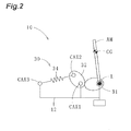
Fig. 2 is a basic structural drawing schematically illustrating a gravity compensation mechanism of the robot. -
Fig. 3 is an explanatory drawing of an exemplary modification of a second non-circular gear of the gravity compensation mechanism of the robot. -
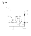
Fig. 4A is a first explanatory drawing of operation of the robot. -
Fig. 4B is a second explanatory drawing of operation of the robot. -
Fig. 4C is a third explanatory drawing of operation of the robot. -
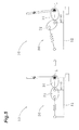
Fig. 5 is an explanatory drawing illustrating a reduction ratio of non-circular gears of the gravity compensation mechanism of the robot. -
Fig. 6A is an explanatory drawing illustrating a first exemplary configuration of the gravity compensation mechanism of the robot. -
Fig. 6B is an explanatory drawing illustrating a second exemplary configuration of the gravity compensation mechanism of the robot. -
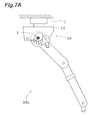
Fig. 7A is an explanatory drawing of the robot mounted on a ceiling. -
Fig. 7B is an explanatory drawing of the robot mounted on a wall. -
Fig. 8 is an explanatory drawing illustrating a front view of a robot according to a second exemplary embodiment of the present invention. - An exemplary embodiment embodying the present invention will be described referring to the attached drawings to promote understanding of the present invention. In each of the drawings, the part which is not related to the description may be omitted.
- A
robot 10 according to a first exemplary embodiment of the present invention is, for example, an industrial robot with six axes as illustrated inFig. 1 . - The
robot 10 includes aswing part 12 mounted on a floor F which is a mounting surface, afirst arm part 14, asecond arm part 16, athird arm part 18, awrist part 22, and aflange part 24. Therobot 10 also includes agravity compensation mechanism 30. - The
swing part 12 can rotate about a pivot (rotation axis) S extending in the direction intersecting with the floor F. - One end portion of the
first arm part 14 is provided on theswing part 12, and thefirst arm part 14 can rotate about a rotation axis L which is parallel to the floor F. - One end portion of the
second arm part 16 is provided on the distal end portion of thefirst arm part 14, and thesecond arm part 16 can rotate about a rotation axis U which is parallel to the rotation axis L. - One end portion of the
third arm part 18 is provided on the distal end portion of thesecond arm part 16, and thethird arm part 18 can rotate about a rotation axis R extending in the longitudinal direction of thesecond arm part 16. - One end portion of the
wrist part 22 is provided on the distal end portion of thethird arm part 18, and thewrist part 22 can rotate about a rotation axis B which intersects with the longitudinal direction of thethird arm part 18. - The
flange part 24 can rotate about a rotation axis T extending along the longitudinal direction of thewrist part 22. -
Fig. 1 illustrates a side view of therobot 10, and the arrow inFig. 1 shows the direction of rotation about each axis. The rotational motion about each axis is controlled by a well-known control system using a servo motor or the like. For convenience of description, the rightward direction in a sheet ofFig. 1 is defined as the forward direction of the robot, and the leftward direction in the sheet ofFig. 1 is defined as the rearward direction of the robot. - As illustrated in
Fig. 2 , thegravity compensation mechanism 30 includes a firstnon-circular gear 31 which is a driving gear, a secondnon-circular gear 32 which is a follower gear, and an extension/contraction body 34. InFig. 2 , thefirst arm part 14, thesecond arm part 16, thethird arm part 18, thewrist part 22, and theflange part 24 are schematically illustrated together as an arm AM. The center of gravity CG of the arm AM is also illustrated in the drawing. Each gear is schematically illustrated and teeth thereof are not shown. - The first
non-circular gear 31 has, for example, an elliptic shape. The firstnon-circular gear 31 is configured to rotate about the rotation axis L of thefirst arm part 14 together with thefirst arm part 14. The rotation axis L passes a position offset from the central portion of the firstnon-circular gear 31 in a front view (when viewed from the direction in which the rotation axis L of the firstnon-circular gear 31 extends). - The second
non-circular gear 32 has, for example, an elliptic shape. The secondnon-circular gear 32 meshes with and is driven by the firstnon-circular gear 31. The secondnon-circular gear 32 is allowed to rotate about a coupling shaft CAX1 provided in theswing part 12. The coupling shaft CAX1 is arranged to be offset from the central portion of the secondnon-circular gear 32 in a front view (when viewed from the direction in which the coupling shaft CAX1, which is the rotation axis of the secondnon-circular gear 32, extends). - The extension/
contraction body 34 can extend and contract as the secondnon-circular gear 32 rotates to produce force in the direction of extension and contraction. Examples of the extension/contraction body 34 include a coil spring and an air spring. - One end portion of the extension/
contraction body 34 is rotatably coupled to the secondnon-circular gear 32 via a coupling shaft CAX2 provided in the secondnon-circular gear 32. The coupling shaft CAX2 is arranged at a position offset from the central portion of the secondnon-circular gear 32 in a front view and being the opposite side of the coupling shaft CAX1 with the central portion therebetween. - Note that, as illustrated in
Fig. 3 , the secondnon-circular gear 32 may include a connectingmember 36 to which distal end portion the coupling shaft CAX2 is provided. That is, one end portion of the extension/contraction body 34 may rotatably be coupled to the secondnon-circular gear 32 via the coupling shaft CAX2 provided in the connectingmember 36. - The other end portion of the extension/
contraction body 34 is rotatably coupled to theswing part 12 via a coupling shaft CAX3 provided in theswing part 12. - Now, operation of the
robot 10 will be described. - As illustrated in
Fig. 4A , the secondnon-circular gear 32 and the extension/contraction body 34 are arranged so that the coupling shaft CAX1 and the coupling shaft CAX2 in the secondnon-circular gear 32 and the coupling shaft CAX3 provided in theswing part 12 are aligned when the center of gravity CG of the arm AM is positioned just above the rotation axis L, in other words, when there is no need to produce gravity compensation torque about the rotation axis L. In this state, the extension/contraction body 34 produces force F1 to pull the coupling shaft CAX2 in the linear direction defined by the coupling shaft CAX1 and the coupling shaft CAX2. The force F1 however does not act to rotate the firstnon-circular gear 31. So that no gravity compensation torque about the rotation axis L of the firstnon-circular gear 31 is produced via the secondnon-circular gear 32. - As illustrated in
Fig. 4B , when the arm AM tilts rearward, the gravitational force acting on the center of gravity CG produces a gravitational torque Tcg2 about the rotation axis L. On the other hand, by the firstnon-circular gear 31 rotating counter-clockwise inFig. 4B , the secondnon-circular gear 32 rotates clockwise to extend the extension/contraction body 34. The extended extension/contraction body 34 produces force F2 which hinders the rotation of the secondnon-circular gear 32. The force F2 produces a gravity compensation torque T2 about the rotation axis L via the secondnon-circular gear 32. The gravity compensation torque T2 cancels the gravitational torque Tcg2 produced about the rotation axis L to balance the force acting on the arm AM. - As illustrated in
Fig. 4C , when the arm AM tilts forward, the gravitational force acting on the center of gravity CG produces a gravitational torque Tcg3 about the rotation axis L. On the other hand, by the firstnon-circular gear 31 rotating clockwise inFig. 4C , the secondnon-circular gear 32 rotates counter-clockwise to extend the extension/contraction body 34. The extended extension/contraction body 34 produces force F3 which hinders the rotation of the secondnon-circular gear 32. The force F3 produces a gravity compensation torque T3 about the rotation axis L via the secondnon-circular gear 32. The gravity compensation torque T3 cancels the gravitational torque Tcg3 produced about the rotation axis L to balance the force acting on the arm AM. - As illustrated in
Fig. 5 , the reduction ratio changes from a1 : b1 to a2 : b2 according to rotational positions of the firstnon-circular gear 31 and the secondnon-circular gear 32. The relationship between the rotational positions of the firstnon-circular gear 31 and the secondnon-circular gear 32 and the reduction ratio can be changed by suitably designing pitch curves of bothgears - A designer therefore can design the shapes of the first
non-circular gear 31 and the secondnon-circular gear 32, once the relationship between the rotational position and the reduction ratio is determined so as to satisfy the output torque property (gravity compensation torque property) required of thegravity compensation mechanism 30. In other words, the designer can change the gravity compensation torque property by changing the shapes of the firstnon-circular gear 31 and the secondnon-circular gear 32, which means that a high flexibility in designing a gravity compensation torque property is ensured. - Further, the
gravity compensation mechanism 30 is simply configured with the firstnon-circular gear 31 and the secondnon-circular gear 32 and therefore has high reliability. - The
gravity compensation mechanism 30 described in the exemplary embodiment may have various exemplary configurations. - A first exemplary configuration may be a
gravity compensation mechanism 30a illustrated inFig. 6A . One end portion of an extension/contraction body 34 of thegravity compensation mechanism 30a is guided by aguide 42 along the longitudinal direction of the extension/contraction body 34 and coupled to a secondnon-circular gear 32 via alink 44. The other end portion of the extension/contraction body 34 is fixed to aswing part 12. One end portion of thelink 44 is coupled to one end portion of the extension/contraction body 34 via a coupling shaft CAX5. The other end portion of thelink 44 is coupled to the secondnon-circular gear 32 via a coupling shaft CAX2. - Therefore, since the rotation of the second
non-circular gear 32 is transferred to the extension/contraction body 34 via thelink 44, the extension/contraction body 34 extends and contracts according to the tilt of the arm AM. Thegravity compensation mechanism 30a can thereby output gravity compensation torque according to a predetermined property. - A second exemplary configuration may be a
gravity compensation mechanism 30b illustrated inFig. 6B . - One end portion of an extension/
contraction body 34 of thegravity compensation mechanism 30b is coupled to the central portion of a secondnon-circular gear 32 without a coupling shaft in between. The entire extension/contraction body 34 rotates about a coupling shaft CAX1 as the secondnon-circular gear 32 rotates (see the arrow shown inFig. 6B ). The other end portion of the extension/contraction body 34 is coupled to one end of alink 46 via a coupling shaft CAX6. The other end portion of thelink 46 is coupled to aswing part 12 via a coupling shaft CAX7. - The length of the extension/
contraction body 34 rotating together with the secondnon-circular gear 32 therefore changes according to the rotational position of the second non-circular gear 32 (posture of the link 46). That is, the extension/contraction body 34 extends and contracts according to the tilt of the arm AM, so that thegravity compensation mechanism 30b can output gravity compensation torque according to a predetermined property. - The robot may be a so-called suspended
robot 10a of which swingpart 12 is mounted on a ceiling C as illustrated inFig. 7A . Further, the robot may be a so-called wall-mountedrobot 10b of which swingpart 12 is mounted on a wall W as illustrated inFig. 7B . - A
robot 100 according to a second exemplary embodiment of the present invention will be described. The same components as therobot 10 according to the first exemplary embodiment are appended with the same reference signs and detailed description will be omitted. - The
robot 100 is, for example, an industrial robot with six-axes as illustrated inFig. 8 . - A
swing part 112 of therobot 100 is mounted on a wall and can swing about a pivot S which intersects with a vertical axis. That is, therobot 100 is a wall-mounted robot.Fig. 8 illustrates the wall-mountedrobot 100 viewed in a direction facing the wall. - In the first exemplary embodiment, the
gravity compensation mechanism 30 is used for the rotation about the rotation axis L. In the second exemplary embodiment, agravity compensation mechanism 130 is used for the rotation about a pivot S. - The
gravity compensation mechanism 130 includes a firstnon-circular gear 131 which is a driving gear, a secondnon-circular gear 132 which is a follower gear, and an extension/contraction body 134. - The first
non-circular gear 131 has, for example, an elliptic shape. The firstnon-circular gear 131 is configured to rotate about the pivot S of theswing part 112 together with theswing part 112. The pivot S passes a position offset from the central portion of the firstnon-circular gear 131 in a front view. - The second
non-circular gear 132 has, for example, an elliptic shape. The secondnon-circular gear 132 meshes with and is driven by the firstnon-circular gear 131. The secondnon-circular gear 132 can rotate about a coupling shaft CAX11. The coupling shaft CAX11 is arranged to be offset from the central portion of the secondnon-circular gear 132 in a front view. The coupling shaft CAX11 is provided in a fixedmember 140 fixed on the wall which is a mounting surface. - The extension/
contraction body 134 extends and contracts as the secondnon-circular gear 132 rotates to produce force along the direction of extension and contraction. Examples of the extension/contraction body 134 include a coil spring and an air spring. - One end portion of the extension/
contraction body 134 is rotatably coupled to the secondnon-circular gear 132 via a coupling shaft CAX12 provided in the secondnon-circular gear 132. The coupling shaft CAX12 is provided in a connectingmember 136 fixed to the secondnon-circular gear 132. The coupling shaft CAX12 is arranged at a positon offset from the central portion of the secondnon-circular gear 132 in a front view and being the opposite side of the coupling shaft CAX1 with the central portion therebetween. - The other end portion of the extension/
contraction body 134 is rotatably connected to the fixedmember 140 via a coupling shaft CAX13 provided in the fixedmember 140. - When the
swing part 112 swings, viewing in the direction of the pivot S, the center of gravity of the arm changes according to the swing angle. As a result, the gravitational force acting on the center of gravity produces gravitational torque about the pivot S. At this time, as theswing part 112 swings, the extension/contraction body 134 extends and contracts to produce force, whereby thegravity compensation mechanism 130 can produce gravity compensation torque to cancel the gravitational torque. - Since the
gravity compensation mechanism 130 includes the firstnon-circular gear 131 and the secondnon-circular gear 132, by changing the shapes of these non-circular gears, a high flexibility in designing a gravity compensation torque property is ensured. - Note that, the present invention is not limited to the exemplary embodiments described above. Modifications can be made without changing the spirit of the present invention. For example, configurations of the present invention made by combining a portion or the entire part of the exemplary embodiments and the exemplary modification described above also fall within the technical scope of the present invention.
- In the exemplary embodiments described above, the robot is not limited to an industrial robot with six axes. The number of joints of the robot may arbitrarily be determined. The gravity compensation mechanism can be applied to, for example, an arm part or a leg part of a humanoid robot.
-
- 10, 10a, 10b
- robot
- 12
- swing part
- 14
- first arm part
- 16
- second arm part
- 18
- third arm part
- 22
- wrist part
- 24
- flange part
- 30
- gravity compensation mechanism
- 30a
- gravity compensation mechanism
- 30b
- gravity compensation mechanism
- 31
- first non-circular gear
- 32
- second non-circular gear
- 34
- extension/contraction body
- 36
- connecting member
- 42
- guide
- 44, 46
- link
- 100
- robot
- 112
- swing part
- 130
- gravity compensation mechanism
- 131
- first non-circular gear
- 132
- second non-circular gear
- 134
- extension/contraction body
- 136
- connecting member
- 140
- fixed member
- AM
- arm
- C
- ceiling
- CAX1
- coupling shaft
- CAX2
- coupling shaft
- CAX3
- coupling shaft
- CAX5
- coupling shaft
- CAX6
- coupling shaft
- CAX7
- coupling shaft
- CAX11
- coupling shaft
- CAX12
- coupling shaft
- CAX13
- coupling shaft
- CG
- center of gravity
- F
- floor
- S
- pivot
- L, U, R, B, T
- rotation axis
- W
- wall
Claims (5)
- A gravity compensation mechanism comprising:a first non-circular gear configured to rotate about a rotation axis of an arm part of a robot together with the arm part;a second non-circular gear driven by the first non-circular gear; andan extension/contraction body configured to extend and contract to produce force as the second non-circular gear rotates, one end portion of the extension/contraction body being connected to the second non-circular gear.
- The gravity compensation mechanism according to claim 1,
wherein the extension/contraction body is a coil spring. - The gravity compensation mechanism according to claim 1,
wherein the extension/contraction body is an air spring. - The gravity compensation mechanism according to any one of claims 1 to 3,
wherein the robot includes a swing part configured to swing about a pivot which intersects with a vertical axis,
the swing part is provided in place of the arm part, and
the pivot of the swing part is provided in place of the rotation axis of the arm part. - A robot comprising
a gravity compensation mechanism including
a first non-circular gear configured to rotate about a rotation axis of an arm part of the robot together with the arm part,
a second non-circular gear driven by the first non-circular gear, and
an extension/contraction body configured to extend and contract to produce force as the second non-circular gear rotates, one end portion of the extension/contraction body being connected to the second non-circular gear.
Applications Claiming Priority (1)
| Application Number | Priority Date | Filing Date | Title |
|---|---|---|---|
| PCT/JP2012/060962 WO2013161006A1 (en) | 2012-04-24 | 2012-04-24 | Gravity compensation mechanism and robot |
Publications (1)
| Publication Number | Publication Date |
|---|---|
| EP2842698A1 true EP2842698A1 (en) | 2015-03-04 |
Family
ID=49482377
Family Applications (1)
| Application Number | Title | Priority Date | Filing Date |
|---|---|---|---|
| EP12875443.9A Withdrawn EP2842698A1 (en) | 2012-04-24 | 2012-04-24 | Gravity compensation mechanism and robot |
Country Status (5)
| Country | Link |
|---|---|
| US (1) | US20150040712A1 (en) |
| EP (1) | EP2842698A1 (en) |
| JP (1) | JPWO2013161006A1 (en) |
| CN (1) | CN104245250A (en) |
| WO (1) | WO2013161006A1 (en) |
Cited By (3)
| Publication number | Priority date | Publication date | Assignee | Title |
|---|---|---|---|---|
| DE102019002649B4 (en) | 2018-04-17 | 2022-06-09 | Fanuc Corporation | Installation mode determination device, computer program and recording medium for determining an installation mode |
| WO2023107020A1 (en) * | 2021-12-10 | 2023-06-15 | Ocali̇s Mühendi̇sli̇k Anoni̇m Şi̇rketi̇ | Arm supporting apparatus |
| WO2025078019A1 (en) * | 2023-10-13 | 2025-04-17 | Abb Schweiz Ag | Arrangement for industrial robot, and industrial robot |
Families Citing this family (18)
| Publication number | Priority date | Publication date | Assignee | Title |
|---|---|---|---|---|
| KR101683526B1 (en) * | 2015-02-12 | 2016-12-07 | 현대자동차 주식회사 | Counter-balancing linkage unit |
| JP6654308B2 (en) * | 2015-08-03 | 2020-02-26 | パスカルエンジニアリング株式会社 | Robot balancer device |
| WO2018051665A1 (en) | 2016-09-13 | 2018-03-22 | ソニー株式会社 | Medical support arm device, medical system, and surgical microscope system |
| DE102017203595B3 (en) * | 2017-03-06 | 2018-07-12 | Deutsches Zentrum für Luft- und Raumfahrt e.V. | The robotic articulation |
| DE202017006955U1 (en) * | 2017-07-06 | 2019-01-16 | Kuka Deutschland Gmbh | Robotic arm with a weight compensation device |
| IT201700081177A1 (en) | 2017-07-18 | 2019-01-18 | Iuvo S R L | "Operator assistance assistance system" |
| CN107914284B (en) * | 2017-11-08 | 2021-03-19 | 燕山大学 | A gravity compensation mechanism for a rotating joint mechanical arm |
| CN109986598B (en) * | 2017-12-29 | 2022-04-05 | 沈阳新松机器人自动化股份有限公司 | Balance cylinder and industrial robot |
| CN108284456A (en) * | 2018-01-31 | 2018-07-17 | 哈尔滨工业大学 | Gravitational compensation method in sensor load external force measurement based on dimensionality reduction parsing |
| CN109352678B (en) * | 2018-09-25 | 2020-11-27 | 珠海格力电器股份有限公司 | Gravity compensation method and device for robot shaft and robot |
| WO2020217191A1 (en) * | 2019-04-22 | 2020-10-29 | Iuvo S.R.L | System for assisting an operator in exerting efforts |
| SE543510C2 (en) * | 2019-07-02 | 2021-03-16 | Bae Systems Haegglunds Ab | Arrangement and method for balancing a gun barrel of a vehicle mounted weapon system |
| CN110202609B (en) * | 2019-07-04 | 2022-06-07 | 哈尔滨工业大学 | Spring boosting mechanism for compensating moment of rod piece |
| CN112223305B (en) * | 2020-09-23 | 2021-05-07 | 合肥铁榔头教育科技有限公司 | Waist joint of humanoid robot and implementation method |
| CN113459078B (en) * | 2021-06-28 | 2024-04-19 | 安徽工程大学 | Non-circular gear joint robot and design method thereof |
| CN116098713B (en) * | 2021-11-11 | 2025-09-23 | 深圳市精锋医疗科技股份有限公司 | Main wrist, main operating equipment and surgical robot |
| CN114459675A (en) * | 2021-12-30 | 2022-05-10 | 中国航空工业集团公司北京长城计量测试技术研究所 | Large-amplitude sine force generating device |
| JP2025005044A (en) * | 2023-06-27 | 2025-01-16 | 川崎重工業株式会社 | Painting robot |
Family Cites Families (10)
| Publication number | Priority date | Publication date | Assignee | Title |
|---|---|---|---|---|
| JPS55106787A (en) * | 1979-02-05 | 1980-08-15 | Hitachi Ltd | Device for balancing gravity |
| JPS61144993U (en) * | 1985-03-01 | 1986-09-06 | ||
| JPH0569378A (en) | 1991-09-11 | 1993-03-23 | Hitachi Ltd | Gravitation balancing device, articulated robot, and wrist device for robot |
| JPH07196150A (en) * | 1994-01-10 | 1995-08-01 | Morita & Co:Kk | Gripping device for coil spring |
| JPH10156770A (en) * | 1996-12-04 | 1998-06-16 | Komatsu Ltd | Handling robot |
| DE10393671D2 (en) * | 2002-08-23 | 2005-07-21 | Boehm Hubertus | Weight compensation system for devices with rotary axes |
| CN1319703C (en) * | 2004-07-09 | 2007-06-06 | 北京理工大学 | Six-freedom remote control arm with gravity compensation and length regulation |
| JP2009291843A (en) * | 2008-06-02 | 2009-12-17 | Tokyo Institute Of Technology | Manipulator |
| JP5432645B2 (en) * | 2009-09-14 | 2014-03-05 | トヨタ自動車株式会社 | Self-weight compensation mechanism |
| JP5256170B2 (en) * | 2009-11-05 | 2013-08-07 | 住友重機械工業株式会社 | Reduction gear |
-
2012
- 2012-04-24 EP EP12875443.9A patent/EP2842698A1/en not_active Withdrawn
- 2012-04-24 CN CN201280072627.7A patent/CN104245250A/en active Pending
- 2012-04-24 JP JP2014512062A patent/JPWO2013161006A1/en active Pending
- 2012-04-24 WO PCT/JP2012/060962 patent/WO2013161006A1/en not_active Ceased
-
2014
- 2014-10-23 US US14/521,466 patent/US20150040712A1/en not_active Abandoned
Non-Patent Citations (1)
| Title |
|---|
| See references of WO2013161006A1 * |
Cited By (3)
| Publication number | Priority date | Publication date | Assignee | Title |
|---|---|---|---|---|
| DE102019002649B4 (en) | 2018-04-17 | 2022-06-09 | Fanuc Corporation | Installation mode determination device, computer program and recording medium for determining an installation mode |
| WO2023107020A1 (en) * | 2021-12-10 | 2023-06-15 | Ocali̇s Mühendi̇sli̇k Anoni̇m Şi̇rketi̇ | Arm supporting apparatus |
| WO2025078019A1 (en) * | 2023-10-13 | 2025-04-17 | Abb Schweiz Ag | Arrangement for industrial robot, and industrial robot |
Also Published As
| Publication number | Publication date |
|---|---|
| WO2013161006A1 (en) | 2013-10-31 |
| US20150040712A1 (en) | 2015-02-12 |
| CN104245250A (en) | 2014-12-24 |
| JPWO2013161006A1 (en) | 2015-12-21 |
Similar Documents
| Publication | Publication Date | Title |
|---|---|---|
| US20150040712A1 (en) | Gravity compensation mechanism and robot | |
| JP5403303B2 (en) | Parallel mechanism | |
| EP2383082B1 (en) | Robot hand | |
| CN105307824B (en) | Industrial robot with a drive layout set on a cantilever | |
| US7407208B2 (en) | Joint drive mechanism and robot hand | |
| KR102009311B1 (en) | Hand of robot | |
| JP2011255493A (en) | Actuator module usable for various forms of joints | |
| WO2017149987A1 (en) | Flapping device | |
| WO2015166214A1 (en) | Compliant actuator | |
| CN107000202B (en) | Multi-joint robot and module thereof | |
| JP5459194B2 (en) | Articulated robot and robot joint structure | |
| CN105881585A (en) | Counterbalancing Linkage Mechanism | |
| JP6105024B2 (en) | Rotation drive mechanism in robot | |
| JP5521674B2 (en) | robot | |
| JP2013043279A (en) | Low-stroke actuation for serial robot | |
| JP2020015152A (en) | Robot arm | |
| CN106163746A (en) | The articulation mechanism of humanoid robot | |
| KR101207853B1 (en) | Actuator module applicable in various joint type and joint structure using the same | |
| CN104816313A (en) | Articulated robot | |
| CN220593176U (en) | Finger, mechanical gripper and robot thereof | |
| JP4442464B2 (en) | Articulated arm mechanism | |
| KR101867763B1 (en) | Bending stiffness control device for joint device | |
| US20170050312A1 (en) | Parallel Kinematics Robot With Rotational Degrees Of Freedom | |
| JP6687928B2 (en) | Joint drive device and multi-axis manipulator | |
| JPH02218583A (en) | industrial robot |
Legal Events
| Date | Code | Title | Description |
|---|---|---|---|
| PUAI | Public reference made under article 153(3) epc to a published international application that has entered the european phase |
Free format text: ORIGINAL CODE: 0009012 |
|
| 17P | Request for examination filed |
Effective date: 20141008 |
|
| AK | Designated contracting states |
Kind code of ref document: A1 Designated state(s): AL AT BE BG CH CY CZ DE DK EE ES FI FR GB GR HR HU IE IS IT LI LT LU LV MC MK MT NL NO PL PT RO RS SE SI SK SM TR |
|
| AX | Request for extension of the european patent |
Extension state: BA ME |
|
| DAX | Request for extension of the european patent (deleted) | ||
| STAA | Information on the status of an ep patent application or granted ep patent |
Free format text: STATUS: THE APPLICATION HAS BEEN WITHDRAWN |
|
| 18W | Application withdrawn |
Effective date: 20150831 |