EP2842149B1 - Dispositif de verrouillage amovible pour appareillage electrique - Google Patents
Dispositif de verrouillage amovible pour appareillage electrique Download PDFInfo
- Publication number
- EP2842149B1 EP2842149B1 EP13718324.0A EP13718324A EP2842149B1 EP 2842149 B1 EP2842149 B1 EP 2842149B1 EP 13718324 A EP13718324 A EP 13718324A EP 2842149 B1 EP2842149 B1 EP 2842149B1
- Authority
- EP
- European Patent Office
- Prior art keywords
- handle
- ratchet
- locking
- locking device
- support bracket
- Prior art date
- Legal status (The legal status is an assumption and is not a legal conclusion. Google has not performed a legal analysis and makes no representation as to the accuracy of the status listed.)
- Not-in-force
Links
Images

Classifications
-
- H—ELECTRICITY
- H01—ELECTRIC ELEMENTS
- H01H—ELECTRIC SWITCHES; RELAYS; SELECTORS; EMERGENCY PROTECTIVE DEVICES
- H01H9/00—Details of switching devices, not covered by groups H01H1/00 - H01H7/00
- H01H9/20—Interlocking, locking, or latching mechanisms
- H01H9/28—Interlocking, locking, or latching mechanisms for locking switch parts by a key or equivalent removable member
- H01H9/281—Interlocking, locking, or latching mechanisms for locking switch parts by a key or equivalent removable member making use of a padlock
- H01H9/282—Interlocking, locking, or latching mechanisms for locking switch parts by a key or equivalent removable member making use of a padlock and a separate part mounted or mountable on the switch assembly and movable between an unlocking position and a locking position where it can be secured by the padlock
-
- H—ELECTRICITY
- H01—ELECTRIC ELEMENTS
- H01H—ELECTRIC SWITCHES; RELAYS; SELECTORS; EMERGENCY PROTECTIVE DEVICES
- H01H9/00—Details of switching devices, not covered by groups H01H1/00 - H01H7/00
- H01H9/20—Interlocking, locking, or latching mechanisms
- H01H9/28—Interlocking, locking, or latching mechanisms for locking switch parts by a key or equivalent removable member
- H01H9/286—Interlocking, locking, or latching mechanisms for locking switch parts by a key or equivalent removable member making use of a removable locking part acting directly on the operating part
Definitions
- the invention relates to a device for locking an electrical equipment which is intended to prevent the movement of a component of the equipment.
- the invention more particularly relates to a locking device which is adapted to be removably mounted on the electrical equipment.
- the mobile components able to open or close the power transmission line are driven by a device. control.
- This control device comprises in particular a ratchet which is mechanically connected to the moving components and which is movably mounted in the control device between a rest position corresponding to a closed position of the disconnector, and an actuating position corresponding to an open state of the switch.
- the control device When an operator must intervene on the disconnector, the control device must be locked in an actuating position, that is to say in a position for which the disconnector is open, to guarantee intervention in a secure manner for the operator.
- the locking device comprises cavities of complementary shapes to the levers to be locked.
- This locking device is adapted to the blocking of a prominent component and only this component, it can not block other components of the equipment, along with a lever.
- the document CA2151867 describes a lever which is able to block the movement of a component of the apparatus, according to the operating position of the lever. This lever is thus adapted for blocking a single component of the apparatus.
- the lever is moved to its blocking position only when an operator actuates a push button, it is therefore possible that an operator does not act on the button, which would result in not achieving the blocking.
- EP-A-0610143 also describes a device for locking a control device of an electrical equipment.
- the object of the invention is to propose a locking device for electrical equipment, preferably for a line disconnector.
- high voltage current transport which allows a double locking of the control device, thus ensuring redundancy of the lock.
- the invention also aims to provide a locking device that can be implemented on an apparatus that was not designed with this locking device.
- the invention proposes a device for locking a control device of medium or high voltage electrical equipment, the control device comprising a support plate, a ratchet which is pivotally mounted with respect to the support plate around the a first axis between a rest position and an operating position of the apparatus, and a ratchet locking device in its rest position, the locking device being movable relative to the support plate between an active position ratchet lock and an inactive position allowing the ratchet to pivot relative to the support plate, characterized in that the locking device is adapted to be mounted on the apparatus removably and is adapted to lock the ratchet in its rest position and lock the locking device in its locking position of the ratchet when mounted on the apparatus.
- Such a locking device makes it possible, while simultaneously immobilizing the ratchet and the means blocking, to ensure redundancy of the locking of the control device.
- the locking device since the locking device is removable, it can be used successively on several similar devices or be mounted on an apparatus for which such a locking device has not been provided for its design.
- the locking device comprises a main body which is adapted to come into simultaneous contact with the ratchet and the locking device for their simultaneous locking, and a handle comprising means for securing the locking device on the apparatus.
- the body comprises a bearing face which is adapted to come into contact with a component of the locking device for locking the locking device.
- the body comprises means for its positioning transversely and vertically relative to the support plate and in that the handle comprises means for positioning and maintaining the position of the body longitudinally relative to the support plate.
- the handle comprises a tongue which is adapted to engage in at least one groove complementary to the support plate.
- the handle is able to deform elastically under manual action to allow the release of the tongue out of the groove.
- the handle consists of a metal blade folded U-shaped, a first branch is fixed to the main body, and the second branch carries the tongue and is adapted to be moved towards the first leg by elastic deformation of the handle.
- the locking device comprises a wedge adapted to be mounted between the branches of the handle to prevent the elastic deformation of the handle and in that each leg of the handle and the wedge each comprise a hole adapted to be traversed by a rod such as the handle of a padlock.
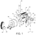
- figure 1 a part of a control device 10 of an electrical equipment such as a switch of high or very high voltage current transmission line.
- the control device 10 comprises a support plate 12 which here consists of a pair of parallel plates 14 spaced transversely from one another.
- Each plate comprises in particular two blades 15s, 15i of longitudinal main orientation, which are offset vertically.
- a magnetic core 18 is mounted between the two plates 14.
- the magnetic core 18 is made in two parts, a first part 24 is fixed to the support plate 12 by clamping between the two plates 14 by means of two bolts 20, 22, the other part 26 is fixed to the plate support 12 removably.
- connection of the removable part 26 to the support plate 12 is formed on the one hand by means of two pins 28 arranged with each side of the removable portion 26, each of which is adapted to be received in a longitudinal groove 30 formed in the free longitudinal end of the lower blade 15i. These pins 28 make it possible to vertically position the removable part 26 with respect to the support plate 12.
- connection of the removable part 26 is also achieved by a spring blade 32 providing a maintenance of the removable part 26, bearing longitudinally against the fixed part 24.
- the leaf spring 32 is fixed to the support plate 12, it is received in vertical grooves 33 open upwards, which are formed in the free longitudinal ends of the upper blades 15s and lower blades 15i.
- the control device also comprises an annular winding 34, part of which is introduced into the core 18 between the upper blades 15s and the lower blades 15i and the winding is arranged around the lower blades 15i.
- the control device also comprises a ratchet 36 which is pivotally mounted relative to the support plate 12 about a transverse axis A formed at a bolt 22.
- the ratchet 36 is connected to the live parts of the disconnector via a not shown connecting arm.
- the ratchet 36 is mounted on the plate outside the plates 14, that is to say that it is shifted transversely with respect to the magnetic core 18.
- the ratchet 36 is movable relative to the support plate 12 between a rest position shown in the figures, and an actuating position.
- the rest position of the ratchet corresponds to an open state of the disconnector, that is to say a state of the disconnector for which there is no current flow through the disconnector.
- the actuating position of the ratchet corresponds to a closed state of the disconnector, that is to say a state of the disconnector for which an electric current flows through the disconnector.
- the ratchet 36 is biased towards the rest position by means of a return spring 38.
- the control device 10 also includes a locking device of the ratchet 36 in its rest position, preventing an error closing of the disconnector.
- the locking device comprises an armature 40 arranged between the lower blades 15i, which carries a pin 42 protruding transversely with respect to the support plate 12, on the same side as the ratchet 36.
- the armature 40 is able to move between a rest position in which the pin 42 cooperates with a portion of the ratchet 36 to prevent the ratchet 36 from moving towards its actuating position, and an unobstructed position in which the pin 42 does not move. may not prevent the ratchet 36 from moving to its actuating position.
- the displacement of the armature 40 between its rest position and its released position consists of a pivoting around a second transverse axis B.
- a spring 44 resets the armature 40 and the pin 42 to their rest position. Means not shown cause the armature 40 to its unobstructed position.
- This securing of the intervention is effected by locking the control device 10 of the disconnector.
- control device 10 is deactivated by the disassembly of the magnetic core 18, that is to say by dismounting the mobile part 26 of the core 18.
- control device 10 is mechanically locked in its rest position, to prevent the ratchet 36 from moving to its active position.
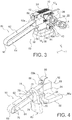
- the mechanical blocking of the control device 10 is achieved by means of a locking device 50 shown in figures 2 and following.
- the locking device 50 consists of a removable element which is adapted to be mounted on the control device 10 at the beginning of an operator intervention, to lock it in the rest position of the ratchet 36.
- the locking device 50 cooperates with the ratchet 36 to prevent any pivoting of the ratchet 36 towards its actuated position.
- the locking device 50 also cooperates with the locking device to hold it in its rest position
- the locking device 50 comprises a body 52 which is adapted with the armature 40 to maintain it in its rest position.
- the body 52 has a bearing face 54 which is of complementary shape to the shape of a face opposite the armature 40.
- the complementary shape between the bearing face 54 and the face opposite the armature prevents rotation of the armature 40 about its transverse pivot axis B.
- the body 52 also includes a finger 56 which is offset transversely relative to the body 52, which extends mainly longitudinally and a free end 56a is adapted to come into contact with the ratchet 36 to prevent the movement of the ratchet 36 to its position actuating.
- the assembly of the locking device 50 with the control device 10 is achieved by the insertion of the body 52 on the support plate 12, between the parallel plates 14.
- the transverse width of the body 52 is thus substantially equal to the transverse distance between the two parallel plates 14, thus achieving the transverse positioning of the body 52 with respect to the support plate 12.
- the body 52 has two shoulders 58 projecting transversely, which are distributed on either side of the body 52.
- each of these shoulders 58 is adapted to be received between the blades 15s, 15i of a plate 14, its vertical dimension is substantially equal to the vertical distance between the two blades 15s, 15i of the plate 14, thus achieving the vertical positioning of the body 52 relative to the support plate 12. Also, each shoulder 58 is elongated longitudinally, preventing any pivoting of the body 52 relative to the support plate 12 in a vertical longitudinal plane.
- the locking device 50 also comprises a handle 60 which is fixed to the body, which allows the handling of the locking device 50 and which also realizes the longitudinal positioning of the locking device 50 with respect to the support plate 12.
- the handle 60 consists of a U-shaped folded metal blade having two parallel branches 62, 64 of longitudinal main orientation which are offset vertically with respect to one another, a first branch 62 of which is fixed to the body 52 , and whose second lower leg 64 is adapted to cooperate with the support plate 12 for positioning and maintaining the position of the body 52 longitudinally relative to the plate.
- the handle 60 is located longitudinally relative to the body 52 on the opposite side to the bearing face 54 and the free end of the finger 56.
- the handle is located on the left side of the body 52.
- the first leg 62 thus extends longitudinally away from the plate 52 from a first end 62a at which the first leg 62 is fixed to the body 52.
- the first branch 62 and the second branch 64 are interconnected by a bent portion 66 located at their farthest ends of the body 52, that is to say here their left ends.
- the free end 64a of the second leg 64 which is the closest to the body 52, is folded downwardly forming a tongue 68 generally vertical transverse.
- the tongue 68 is adapted to be received in the vertical groove 33 made in each of the lower blades 15i, when the locking device 50 is mounted on the control device 10.
- the tongue 68 makes it possible to lock the locking device 50 in translation longitudinally with respect to the support plate 12.
- the grooves 33 are open vertically upwards.
- the tongue 68 is introduced into the grooves 33 or is removed from the grooves 33 by a vertical movement downwards for its introduction, or by a vertical upward movement for its extraction.
- the insertion and removal of the tongue 68 in / out of the grooves 33 is effected by the elastic deformation of the handle 60, bringing the branches 62, 64 towards one another. During this deformation of the handle 60, only the free end of the lower branch 64, which carries the tongue 68 moves upwards.
- the tongue 68 can not bear longitudinally against the free end of each lower blade 15i, thus making it possible for the body 52 to move relative to the support plate 12.
- the elasticity of the handle recalls resiliently the tab 68 downward, to fit into the grooves 33 where appropriate.
- the handle 60 is made from a metal blade, for example a spring steel, whose thickness is defined so that the elastic deformation of the handle 60 can be performed manually by an operator.
- each leg of the handle 60 is about 100 millimeters
- the handle 60 is made of a spring steel 1 millimeter thick.
- the body 52 of the locking means 50 is held in a position relative to the support plate 12 in which it is simultaneously resting against the ratchet 36 and the armature 40, thus preventing any movement of the ratchet 36 towards its actuating position.
- the locking device 50 When the locking device 50 is mounted on the control device 10, during a human intervention on the disconnector, it is preferable to prevent the locking device 50 from being disassembled by a person other than the operator.
- the locking device 50 is adapted to be immobilized by means of a wedge 70 inserted between the arms 62, 64 of the handle 60, to prevent their approximation.
- the tongue 68 can not be moved upwards, it can not be removed from the grooves 33 of the lower blades 15i.
- the shim 70 comprises a central portion 72 which is received between the arms 62, 64 of the handle 60 and two wings 74 distributed on either side of the arms 62, 64 of the handle 60, which make it possible to prevent the exit of hold 70 out of the handle.
- the central portion 72 of the shim 70 further comprises a vertical hole (not shown) which is aligned with holes 76 made in the branches 62, 64 of the handle 60 when the shim is in position, these holes 76 are capable of being crossed by the handle 78 of a padlock 80.
- the handle 60 has two pairs of holes 76, a first pair of holes 76 is located at the free end of the lower leg 64 of the handle 60, and is associated with the wedge 70 and the padlock 80 when the it is desired that the shim 70 prevent the tongue 68 from moving.
- a second pair of holes 76 is located at the bent portion 66, it is associated with the shim 70 and the padlock 80 when it is desired to be able to move the tongue 68, in order to set up the locking device 50 or the remove from the control device 10.
- the locking device 50 forms an apparatus which is adapted to be mounted on the control device 10 only when the control device 10 is to be locked.
- the locking device 50 which has just been described is able to be removed from the disconnector when not in use, the same locking device 50 can be used for the maintenance of multiple disconnectors.
- the design of the locking device 50 is further defined according to the control device on which it is to be mounted. This design can also be defined for a control device that was not originally designed to receive such a locking device 50.
Landscapes
- Switch Cases, Indication, And Locking (AREA)
- Breakers (AREA)
- Details Of Connecting Devices For Male And Female Coupling (AREA)
- Mounting Of Printed Circuit Boards And The Like (AREA)
Applications Claiming Priority (2)
| Application Number | Priority Date | Filing Date | Title |
|---|---|---|---|
| FR1253782A FR2990052B1 (fr) | 2012-04-25 | 2012-04-25 | Dispositif de verrouillage amovible pour appareillage electrique |
| PCT/EP2013/058347 WO2013160275A1 (fr) | 2012-04-25 | 2013-04-23 | Dispositif de verrouillage amovible pour appareillage electrique |
Publications (2)
| Publication Number | Publication Date |
|---|---|
| EP2842149A1 EP2842149A1 (fr) | 2015-03-04 |
| EP2842149B1 true EP2842149B1 (fr) | 2016-06-08 |
Family
ID=48182902
Family Applications (1)
| Application Number | Title | Priority Date | Filing Date |
|---|---|---|---|
| EP13718324.0A Not-in-force EP2842149B1 (fr) | 2012-04-25 | 2013-04-23 | Dispositif de verrouillage amovible pour appareillage electrique |
Country Status (5)
| Country | Link |
|---|---|
| EP (1) | EP2842149B1 (enExample) |
| CN (1) | CN104246951B (enExample) |
| FR (1) | FR2990052B1 (enExample) |
| IN (1) | IN2014MN02103A (enExample) |
| WO (1) | WO2013160275A1 (enExample) |
Families Citing this family (6)
| Publication number | Priority date | Publication date | Assignee | Title |
|---|---|---|---|---|
| AU2016204572A1 (en) | 2015-06-30 | 2017-01-19 | Remsafe Pty Ltd | An equipment isolation system |
| US10163592B2 (en) | 2015-06-30 | 2018-12-25 | Remsafe Pty Ltd. | Equipment isolation switch assembly |
| US10222763B2 (en) | 2015-06-30 | 2019-03-05 | Remsafe Pty Ltd | Remote isolation system and mobile device for use in the remote isolation system |
| CN112768272B (zh) * | 2020-12-28 | 2022-10-28 | 施耐德万高(天津)电气设备有限公司 | 一种双电源转换开关的手自动及挂锁结构 |
| CN115527794A (zh) * | 2022-10-26 | 2022-12-27 | 国网山东省电力公司枣庄供电公司 | 一种高压隔离开关 |
| CN116884817B (zh) * | 2023-09-07 | 2023-11-28 | 西门子能源高压开关(杭州)有限公司 | 传动装置、欠压脱扣器以及断路器 |
Family Cites Families (7)
| Publication number | Priority date | Publication date | Assignee | Title |
|---|---|---|---|---|
| US5310969A (en) * | 1992-04-21 | 1994-05-10 | Prinzing Enterprises, Inc. | Switch lockouts |
| FR2701159B1 (fr) * | 1993-02-03 | 1995-03-31 | Merlin Gerin | Dispositif de condamnation mécanique et électrique d'un bloc de télécommande pour disjoncteur modulaire. |
| DE4405934C1 (de) * | 1994-02-24 | 1995-06-14 | Felten & Guilleaume Energie | Blockierbaren Hauptschalter mit einer Vorrichtung zur Überwindung der Blockierung |
| CA2151867C (en) | 1994-06-27 | 2007-09-11 | Raymond K. Seymour | Modular accessory mechanical lockout mechanism |
| US7126067B2 (en) * | 2004-10-13 | 2006-10-24 | Entergy Corporation | Switch blocking apparatus |
| US8350648B2 (en) * | 2008-08-04 | 2013-01-08 | Gus Cueto | Power control device and assembly |
| CN101656163B (zh) * | 2008-08-22 | 2011-11-16 | 东莞安联电器元件有限公司 | 棘轮机构和带有棘轮机构的旋转开关 |
-
2012
- 2012-04-25 FR FR1253782A patent/FR2990052B1/fr active Active
-
2013
- 2013-04-23 WO PCT/EP2013/058347 patent/WO2013160275A1/fr not_active Ceased
- 2013-04-23 EP EP13718324.0A patent/EP2842149B1/fr not_active Not-in-force
- 2013-04-23 CN CN201380022243.9A patent/CN104246951B/zh not_active Expired - Fee Related
- 2013-04-23 IN IN2103MUN2014 patent/IN2014MN02103A/en unknown
Also Published As
| Publication number | Publication date |
|---|---|
| WO2013160275A1 (fr) | 2013-10-31 |
| CN104246951B (zh) | 2016-08-24 |
| EP2842149A1 (fr) | 2015-03-04 |
| FR2990052A1 (fr) | 2013-11-01 |
| IN2014MN02103A (enExample) | 2015-09-04 |
| CN104246951A (zh) | 2014-12-24 |
| FR2990052B1 (fr) | 2014-05-30 |
Similar Documents
| Publication | Publication Date | Title |
|---|---|---|
| EP2842149B1 (fr) | Dispositif de verrouillage amovible pour appareillage electrique | |
| EP2630318B1 (fr) | Dispositif de verrouillage a detection mecanique de fermeture et ouverture | |
| FR3015953A1 (fr) | Systeme de verrouillage de capots | |
| EP3221875B1 (fr) | Système de commande a déclenchement pour pôle de coupure et appareil de coupure | |
| EP3277072B1 (fr) | Dispositif de maintien d'une lame de coupe pivotante | |
| FR2789511A1 (fr) | Installation comportant un appareillage electrique de coupure et un interverrouillage a cable | |
| WO2000042441A1 (fr) | Pince de mesure d'un courant circulant dans des conducteurs | |
| EP1575067A1 (fr) | Sectionneur de terre pivotant à insertion directe et à mouvement simple | |
| EP2538495B1 (fr) | Pince de connexion électrique pour une plage de connexion d'un équipement électrique et appareil électrique équipé d'une telle pince de connexion | |
| FR2969950A1 (fr) | Pince a sertir | |
| EP3266030B1 (fr) | Systeme de commande de pole de coupure avec forçage et appareil de coupure | |
| FR3040581A1 (fr) | Baie de reception de materiel electronique par exemple avionique | |
| FR3061987A1 (fr) | Integration de contacts electriques a un appareil de connexion electrique | |
| EP1785528B1 (fr) | Dispositif de support pour un panneau de signalisation routière | |
| EP2257145B1 (fr) | Dispositif de connexion | |
| FR2899728A1 (fr) | Prise de courant electrique a forces d'insertion et d'extraction controlees | |
| EP3644339A1 (fr) | Appareil de coupure d'un courant électrique | |
| EP2527191B1 (fr) | Système d'ancrage de siège sur plancher | |
| EP2784885A1 (fr) | Elément amovible pour un appareillage modulaire électrique muni d une poignée pivotante | |
| EP0108022B1 (fr) | Disjoncteur à sectionnement de neutre | |
| EP0179961B1 (fr) | Bloc de traction pour treuil linéaire | |
| EP1439621B1 (fr) | Appareillage du type modulaire à monter sur des barres de différentes épaisseurs | |
| EP3588526B1 (fr) | Porte-fusibles | |
| FR3004286A1 (fr) | Dispositif de verrouillage de la manette d'un appareil de protection electrique, et appareil de protection electrique le comportant | |
| FR3038203A1 (fr) | Baie de reception de materiel electronique notamment avionique |
Legal Events
| Date | Code | Title | Description |
|---|---|---|---|
| PUAI | Public reference made under article 153(3) epc to a published international application that has entered the european phase |
Free format text: ORIGINAL CODE: 0009012 |
|
| 17P | Request for examination filed |
Effective date: 20141104 |
|
| AK | Designated contracting states |
Kind code of ref document: A1 Designated state(s): AL AT BE BG CH CY CZ DE DK EE ES FI FR GB GR HR HU IE IS IT LI LT LU LV MC MK MT NL NO PL PT RO RS SE SI SK SM TR |
|
| AX | Request for extension of the european patent |
Extension state: BA ME |
|
| RIN1 | Information on inventor provided before grant (corrected) |
Inventor name: LUESCHER, ROBERT Inventor name: VON ALLMEN, PETER Inventor name: KAELIN, DANIEL |
|
| DAX | Request for extension of the european patent (deleted) | ||
| GRAP | Despatch of communication of intention to grant a patent |
Free format text: ORIGINAL CODE: EPIDOSNIGR1 |
|
| INTG | Intention to grant announced |
Effective date: 20151204 |
|
| RIN1 | Information on inventor provided before grant (corrected) |
Inventor name: KAELIN, DANIEL Inventor name: VON ALLMEN, PETER Inventor name: LUESCHER, ROBERT |
|
| GRAS | Grant fee paid |
Free format text: ORIGINAL CODE: EPIDOSNIGR3 |
|
| RAP1 | Party data changed (applicant data changed or rights of an application transferred) |
Owner name: GENERAL ELECTRIC TECHNOLOGY GMBH |
|
| GRAA | (expected) grant |
Free format text: ORIGINAL CODE: 0009210 |
|
| AK | Designated contracting states |
Kind code of ref document: B1 Designated state(s): AL AT BE BG CH CY CZ DE DK EE ES FI FR GB GR HR HU IE IS IT LI LT LU LV MC MK MT NL NO PL PT RO RS SE SI SK SM TR |
|
| REG | Reference to a national code |
Ref country code: GB Ref legal event code: FG4D Free format text: NOT ENGLISH |
|
| REG | Reference to a national code |
Ref country code: CH Ref legal event code: EP Ref country code: CH Ref legal event code: NV Representative=s name: BOVARD AG, CH |
|
| REG | Reference to a national code |
Ref country code: IE Ref legal event code: FG4D Free format text: LANGUAGE OF EP DOCUMENT: FRENCH |
|
| REG | Reference to a national code |
Ref country code: AT Ref legal event code: REF Ref document number: 805757 Country of ref document: AT Kind code of ref document: T Effective date: 20160715 |
|
| REG | Reference to a national code |
Ref country code: DE Ref legal event code: R096 Ref document number: 602013008399 Country of ref document: DE |
|
| REG | Reference to a national code |
Ref country code: SE Ref legal event code: TRGR |
|
| REG | Reference to a national code |
Ref country code: LT Ref legal event code: MG4D |
|
| REG | Reference to a national code |
Ref country code: NL Ref legal event code: MP Effective date: 20160608 |
|
| PG25 | Lapsed in a contracting state [announced via postgrant information from national office to epo] |
Ref country code: NO Free format text: LAPSE BECAUSE OF FAILURE TO SUBMIT A TRANSLATION OF THE DESCRIPTION OR TO PAY THE FEE WITHIN THE PRESCRIBED TIME-LIMIT Effective date: 20160908 Ref country code: LT Free format text: LAPSE BECAUSE OF FAILURE TO SUBMIT A TRANSLATION OF THE DESCRIPTION OR TO PAY THE FEE WITHIN THE PRESCRIBED TIME-LIMIT Effective date: 20160608 Ref country code: FI Free format text: LAPSE BECAUSE OF FAILURE TO SUBMIT A TRANSLATION OF THE DESCRIPTION OR TO PAY THE FEE WITHIN THE PRESCRIBED TIME-LIMIT Effective date: 20160608 |
|
| REG | Reference to a national code |
Ref country code: AT Ref legal event code: MK05 Ref document number: 805757 Country of ref document: AT Kind code of ref document: T Effective date: 20160608 |
|
| PG25 | Lapsed in a contracting state [announced via postgrant information from national office to epo] |
Ref country code: ES Free format text: LAPSE BECAUSE OF FAILURE TO SUBMIT A TRANSLATION OF THE DESCRIPTION OR TO PAY THE FEE WITHIN THE PRESCRIBED TIME-LIMIT Effective date: 20160608 Ref country code: NL Free format text: LAPSE BECAUSE OF FAILURE TO SUBMIT A TRANSLATION OF THE DESCRIPTION OR TO PAY THE FEE WITHIN THE PRESCRIBED TIME-LIMIT Effective date: 20160608 Ref country code: HR Free format text: LAPSE BECAUSE OF FAILURE TO SUBMIT A TRANSLATION OF THE DESCRIPTION OR TO PAY THE FEE WITHIN THE PRESCRIBED TIME-LIMIT Effective date: 20160608 Ref country code: LV Free format text: LAPSE BECAUSE OF FAILURE TO SUBMIT A TRANSLATION OF THE DESCRIPTION OR TO PAY THE FEE WITHIN THE PRESCRIBED TIME-LIMIT Effective date: 20160608 Ref country code: RS Free format text: LAPSE BECAUSE OF FAILURE TO SUBMIT A TRANSLATION OF THE DESCRIPTION OR TO PAY THE FEE WITHIN THE PRESCRIBED TIME-LIMIT Effective date: 20160608 Ref country code: GR Free format text: LAPSE BECAUSE OF FAILURE TO SUBMIT A TRANSLATION OF THE DESCRIPTION OR TO PAY THE FEE WITHIN THE PRESCRIBED TIME-LIMIT Effective date: 20160909 |
|
| PG25 | Lapsed in a contracting state [announced via postgrant information from national office to epo] |
Ref country code: RO Free format text: LAPSE BECAUSE OF FAILURE TO SUBMIT A TRANSLATION OF THE DESCRIPTION OR TO PAY THE FEE WITHIN THE PRESCRIBED TIME-LIMIT Effective date: 20160608 Ref country code: IS Free format text: LAPSE BECAUSE OF FAILURE TO SUBMIT A TRANSLATION OF THE DESCRIPTION OR TO PAY THE FEE WITHIN THE PRESCRIBED TIME-LIMIT Effective date: 20161008 Ref country code: CZ Free format text: LAPSE BECAUSE OF FAILURE TO SUBMIT A TRANSLATION OF THE DESCRIPTION OR TO PAY THE FEE WITHIN THE PRESCRIBED TIME-LIMIT Effective date: 20160608 Ref country code: EE Free format text: LAPSE BECAUSE OF FAILURE TO SUBMIT A TRANSLATION OF THE DESCRIPTION OR TO PAY THE FEE WITHIN THE PRESCRIBED TIME-LIMIT Effective date: 20160608 Ref country code: SK Free format text: LAPSE BECAUSE OF FAILURE TO SUBMIT A TRANSLATION OF THE DESCRIPTION OR TO PAY THE FEE WITHIN THE PRESCRIBED TIME-LIMIT Effective date: 20160608 |
|
| PG25 | Lapsed in a contracting state [announced via postgrant information from national office to epo] |
Ref country code: PT Free format text: LAPSE BECAUSE OF FAILURE TO SUBMIT A TRANSLATION OF THE DESCRIPTION OR TO PAY THE FEE WITHIN THE PRESCRIBED TIME-LIMIT Effective date: 20161010 Ref country code: PL Free format text: LAPSE BECAUSE OF FAILURE TO SUBMIT A TRANSLATION OF THE DESCRIPTION OR TO PAY THE FEE WITHIN THE PRESCRIBED TIME-LIMIT Effective date: 20160608 Ref country code: AT Free format text: LAPSE BECAUSE OF FAILURE TO SUBMIT A TRANSLATION OF THE DESCRIPTION OR TO PAY THE FEE WITHIN THE PRESCRIBED TIME-LIMIT Effective date: 20160608 Ref country code: SM Free format text: LAPSE BECAUSE OF FAILURE TO SUBMIT A TRANSLATION OF THE DESCRIPTION OR TO PAY THE FEE WITHIN THE PRESCRIBED TIME-LIMIT Effective date: 20160608 |
|
| REG | Reference to a national code |
Ref country code: DE Ref legal event code: R097 Ref document number: 602013008399 Country of ref document: DE |
|
| PLBE | No opposition filed within time limit |
Free format text: ORIGINAL CODE: 0009261 |
|
| STAA | Information on the status of an ep patent application or granted ep patent |
Free format text: STATUS: NO OPPOSITION FILED WITHIN TIME LIMIT |
|
| REG | Reference to a national code |
Ref country code: FR Ref legal event code: PLFP Year of fee payment: 5 |
|
| 26N | No opposition filed |
Effective date: 20170309 |
|
| PG25 | Lapsed in a contracting state [announced via postgrant information from national office to epo] |
Ref country code: DK Free format text: LAPSE BECAUSE OF FAILURE TO SUBMIT A TRANSLATION OF THE DESCRIPTION OR TO PAY THE FEE WITHIN THE PRESCRIBED TIME-LIMIT Effective date: 20160608 Ref country code: SI Free format text: LAPSE BECAUSE OF FAILURE TO SUBMIT A TRANSLATION OF THE DESCRIPTION OR TO PAY THE FEE WITHIN THE PRESCRIBED TIME-LIMIT Effective date: 20160608 |
|
| PGFP | Annual fee paid to national office [announced via postgrant information from national office to epo] |
Ref country code: CH Payment date: 20170427 Year of fee payment: 5 Ref country code: FR Payment date: 20170426 Year of fee payment: 5 Ref country code: DE Payment date: 20170427 Year of fee payment: 5 |
|
| PGFP | Annual fee paid to national office [announced via postgrant information from national office to epo] |
Ref country code: IT Payment date: 20170421 Year of fee payment: 5 Ref country code: SE Payment date: 20170427 Year of fee payment: 5 |
|
| GBPC | Gb: european patent ceased through non-payment of renewal fee |
Effective date: 20170423 |
|
| REG | Reference to a national code |
Ref country code: IE Ref legal event code: MM4A |
|
| PG25 | Lapsed in a contracting state [announced via postgrant information from national office to epo] |
Ref country code: MC Free format text: LAPSE BECAUSE OF FAILURE TO SUBMIT A TRANSLATION OF THE DESCRIPTION OR TO PAY THE FEE WITHIN THE PRESCRIBED TIME-LIMIT Effective date: 20160608 |
|
| PG25 | Lapsed in a contracting state [announced via postgrant information from national office to epo] |
Ref country code: GB Free format text: LAPSE BECAUSE OF NON-PAYMENT OF DUE FEES Effective date: 20170423 Ref country code: LU Free format text: LAPSE BECAUSE OF NON-PAYMENT OF DUE FEES Effective date: 20170423 |
|
| REG | Reference to a national code |
Ref country code: BE Ref legal event code: MM Effective date: 20170430 |
|
| PG25 | Lapsed in a contracting state [announced via postgrant information from national office to epo] |
Ref country code: IE Free format text: LAPSE BECAUSE OF NON-PAYMENT OF DUE FEES Effective date: 20170423 |
|
| PG25 | Lapsed in a contracting state [announced via postgrant information from national office to epo] |
Ref country code: BE Free format text: LAPSE BECAUSE OF NON-PAYMENT OF DUE FEES Effective date: 20170430 |
|
| PG25 | Lapsed in a contracting state [announced via postgrant information from national office to epo] |
Ref country code: MT Free format text: LAPSE BECAUSE OF FAILURE TO SUBMIT A TRANSLATION OF THE DESCRIPTION OR TO PAY THE FEE WITHIN THE PRESCRIBED TIME-LIMIT Effective date: 20160608 |
|
| PG25 | Lapsed in a contracting state [announced via postgrant information from national office to epo] |
Ref country code: AL Free format text: LAPSE BECAUSE OF FAILURE TO SUBMIT A TRANSLATION OF THE DESCRIPTION OR TO PAY THE FEE WITHIN THE PRESCRIBED TIME-LIMIT Effective date: 20160608 |
|
| REG | Reference to a national code |
Ref country code: DE Ref legal event code: R119 Ref document number: 602013008399 Country of ref document: DE |
|
| REG | Reference to a national code |
Ref country code: CH Ref legal event code: PL |
|
| REG | Reference to a national code |
Ref country code: SE Ref legal event code: EUG |
|
| PG25 | Lapsed in a contracting state [announced via postgrant information from national office to epo] |
Ref country code: SE Free format text: LAPSE BECAUSE OF NON-PAYMENT OF DUE FEES Effective date: 20180424 Ref country code: DE Free format text: LAPSE BECAUSE OF NON-PAYMENT OF DUE FEES Effective date: 20181101 |
|
| PG25 | Lapsed in a contracting state [announced via postgrant information from national office to epo] |
Ref country code: CH Free format text: LAPSE BECAUSE OF NON-PAYMENT OF DUE FEES Effective date: 20180430 Ref country code: LI Free format text: LAPSE BECAUSE OF NON-PAYMENT OF DUE FEES Effective date: 20180430 |
|
| PG25 | Lapsed in a contracting state [announced via postgrant information from national office to epo] |
Ref country code: IT Free format text: LAPSE BECAUSE OF NON-PAYMENT OF DUE FEES Effective date: 20180423 Ref country code: FR Free format text: LAPSE BECAUSE OF NON-PAYMENT OF DUE FEES Effective date: 20180430 |
|
| PG25 | Lapsed in a contracting state [announced via postgrant information from national office to epo] |
Ref country code: HU Free format text: LAPSE BECAUSE OF FAILURE TO SUBMIT A TRANSLATION OF THE DESCRIPTION OR TO PAY THE FEE WITHIN THE PRESCRIBED TIME-LIMIT; INVALID AB INITIO Effective date: 20130423 |
|
| PG25 | Lapsed in a contracting state [announced via postgrant information from national office to epo] |
Ref country code: BG Free format text: LAPSE BECAUSE OF FAILURE TO SUBMIT A TRANSLATION OF THE DESCRIPTION OR TO PAY THE FEE WITHIN THE PRESCRIBED TIME-LIMIT Effective date: 20160608 |
|
| PG25 | Lapsed in a contracting state [announced via postgrant information from national office to epo] |
Ref country code: CY Free format text: LAPSE BECAUSE OF FAILURE TO SUBMIT A TRANSLATION OF THE DESCRIPTION OR TO PAY THE FEE WITHIN THE PRESCRIBED TIME-LIMIT Effective date: 20160608 |
|
| PG25 | Lapsed in a contracting state [announced via postgrant information from national office to epo] |
Ref country code: MK Free format text: LAPSE BECAUSE OF FAILURE TO SUBMIT A TRANSLATION OF THE DESCRIPTION OR TO PAY THE FEE WITHIN THE PRESCRIBED TIME-LIMIT Effective date: 20160608 |
|
| PG25 | Lapsed in a contracting state [announced via postgrant information from national office to epo] |
Ref country code: TR Free format text: LAPSE BECAUSE OF FAILURE TO SUBMIT A TRANSLATION OF THE DESCRIPTION OR TO PAY THE FEE WITHIN THE PRESCRIBED TIME-LIMIT Effective date: 20160608 |