EP2841934B1 - Method and structure for chemical analysis - Google Patents
Method and structure for chemical analysis Download PDFInfo
- Publication number
- EP2841934B1 EP2841934B1 EP13781756.5A EP13781756A EP2841934B1 EP 2841934 B1 EP2841934 B1 EP 2841934B1 EP 13781756 A EP13781756 A EP 13781756A EP 2841934 B1 EP2841934 B1 EP 2841934B1
- Authority
- EP
- European Patent Office
- Prior art keywords
- gas flow
- ionized gas
- flow
- ionized
- channel
- Prior art date
- Legal status (The legal status is an assumption and is not a legal conclusion. Google has not performed a legal analysis and makes no representation as to the accuracy of the status listed.)
- Active
Links
- 238000000034 method Methods 0.000 title claims description 22
- 238000004458 analytical method Methods 0.000 title claims description 11
- 239000000126 substance Substances 0.000 title claims description 10
- 238000001914 filtration Methods 0.000 claims description 46
- 150000002500 ions Chemical class 0.000 claims description 38
- 238000000766 differential mobility spectroscopy Methods 0.000 claims 2
- 230000005684 electric field Effects 0.000 description 9
- 238000005259 measurement Methods 0.000 description 6
- 230000007935 neutral effect Effects 0.000 description 6
- 230000037230 mobility Effects 0.000 description 5
- 238000010586 diagram Methods 0.000 description 4
- 239000000243 solution Substances 0.000 description 4
- 238000006386 neutralization reaction Methods 0.000 description 3
- 230000003472 neutralizing effect Effects 0.000 description 3
- 238000010276 construction Methods 0.000 description 2
- 239000000463 material Substances 0.000 description 2
- 239000000758 substrate Substances 0.000 description 2
- 230000006978 adaptation Effects 0.000 description 1
- 239000000443 aerosol Substances 0.000 description 1
- 238000001514 detection method Methods 0.000 description 1
- 238000001746 injection moulding Methods 0.000 description 1
- 238000001871 ion mobility spectroscopy Methods 0.000 description 1
- 238000004989 laser desorption mass spectroscopy Methods 0.000 description 1
- 238000004519 manufacturing process Methods 0.000 description 1
- 239000000203 mixture Substances 0.000 description 1
- 230000010355 oscillation Effects 0.000 description 1
- 239000002245 particle Substances 0.000 description 1
- 230000002285 radioactive effect Effects 0.000 description 1
- 238000004611 spectroscopical analysis Methods 0.000 description 1
Images


Classifications
-
- G—PHYSICS
- G01—MEASURING; TESTING
- G01N—INVESTIGATING OR ANALYSING MATERIALS BY DETERMINING THEIR CHEMICAL OR PHYSICAL PROPERTIES
- G01N27/00—Investigating or analysing materials by the use of electric, electrochemical, or magnetic means
- G01N27/62—Investigating or analysing materials by the use of electric, electrochemical, or magnetic means by investigating the ionisation of gases, e.g. aerosols; by investigating electric discharges, e.g. emission of cathode
- G01N27/622—Ion mobility spectrometry
-
- H—ELECTRICITY
- H01—ELECTRIC ELEMENTS
- H01J—ELECTRIC DISCHARGE TUBES OR DISCHARGE LAMPS
- H01J49/00—Particle spectrometers or separator tubes
- H01J49/26—Mass spectrometers or separator tubes
-
- G—PHYSICS
- G01—MEASURING; TESTING
- G01N—INVESTIGATING OR ANALYSING MATERIALS BY DETERMINING THEIR CHEMICAL OR PHYSICAL PROPERTIES
- G01N27/00—Investigating or analysing materials by the use of electric, electrochemical, or magnetic means
- G01N27/62—Investigating or analysing materials by the use of electric, electrochemical, or magnetic means by investigating the ionisation of gases, e.g. aerosols; by investigating electric discharges, e.g. emission of cathode
- G01N27/622—Ion mobility spectrometry
- G01N27/624—Differential mobility spectrometry [DMS]; Field asymmetric-waveform ion mobility spectrometry [FAIMS]
Definitions
- the present invention relates to a method for chemical analysis, in which
- Figure 1 shows an idealized diagram of the principle of the known FAIMS (Field Asymmetric-waveform Ion-Mobility Spectrometry) aka DMS (Differential Mobility Spectrometry) ion-filtering technique. It is used, for example, to separate different types of ions in a gaseous form. The technique is based on using a high-frequency variable electric field in the ion-filter structure.
- the filter structure consists of, for example, a substrate 102 arranged to form a flow channel 18 and planar filter electrodes 103 arranged on it facing each other.
- the structure permits the passage of only ions 104 that behave in a specific manner in an electric field and filters other ions 105 by neutralizing them electrically.
- the neutralization removes the ions, because the terminal velocity received by the ions in the electric field depends on the field's strength.
- the ions oscillate in the filter at an asymmetrical velocity, which causes a net transfer of ions towards the electrodes in an advantageous direction relative to the field.
- the electrical-field-dependence of the ions is very small and this difference can be compensated by increasing the DC component CV to the frequency-changing field, which cancels a specific type of field dependence.
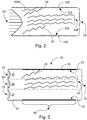
- Figure 2 shows a situation corresponding more to reality in the case of the behaviour of the ions in the aforementioned filtering technique.
- the flow profile 101 of the gas flow shows that the ionized gas flow to be analysed covers the entire cross-section area of the flow channel 18.
- the filter electrodes 103 will inevitably also collect ions 104b that it is particularly desired to pass through the filter.
- These ions 104b which are too close to the edge of the flow channel 18, are neutralized and thus out of the flow that has passed through the filter. This reduces the signal obtained from the system comprising the filter, and also the signal-noise ratio.
- Containment gas to achieve ion concentration toward the center of the flow path in FAIMS is known from WO 2006/060807 .
- the present invention is intended to create a method and structure, which will improve the signal obtained from chemical analysis.
- the characteristic features of the method according to the invention are stated in Claim 1 and those of the structure in Claim 6.
- a parallel mainly non-ionic gas flow which is on at least one side of the ionized gas flow, is led along with the ionized gas flow to the filter structure.
- the use of the solution prevents, or at least reduces, the filtering of ions that it is wished to pass through the filtering.
- the signal-noise ratio of the measurement signal in chemical analysis is also improved.
- the ionized gas flow can be led to the planar filter structure between a mainly non-ionized gas flow.
- the non-ionized gas flow is formed on both sides of the ionized gas flow, so that the flows create a kind of sandwich structure. Ion filtering implemented using the DMS/FAIMS principle can thus be operated in the so-called second-order manner.
- the ionized gas flow can also be flattened by the mainly non-ionized gas flow before both are led to the planar filter structure. In this way, the performance of the filtering can be further improved.
- the invention is the use of a shield flow as a factor preserving the signal, i.e. improving the signal-noise ratio.
- the actual measurement signal can be measured only outside the DMS filter and after it, in one way or another.
- chemical analysis can refer to, for example, the qualitative and/or quantitative detection from a gas flow of substances or similar structural units in the gas flow.
- An aerosol, in which particles are suspended in a gas, can also be considered to be a gas flow within the context of the invention.
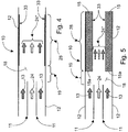
- Figure 3 shows schematically on a very rough level an example of the solution consistent with the invention and the behaviour of the ions in a filter structure 10.
- the so-called second-order solution is based on the idea of taking a planar ionized gas flow 24 to a planar filtering area 28 at one edge of or in the middle of a flow channel 18.
- the ionized gas flow 24, which is the object of the filtering is narrower in relation to the height of the whole flow channel 18.
- a description of the method can start, for example, from the ionization of the gas flow to be analysed. Ionization can take place, for example, outside the flow channel 18, in which case the ions are brought from the actual source to the flow channel 18 along with the gas flow. Ionization of the gas flow can be performed, for example, in some manner of the prior art that is, as such known, or is still under development. Some nonlimiting examples are a radioactive ionizer, a corona charger, the electrospray technique, or some other well-known method.
- the distance from the ionizer (not shown) to the entry opening of the flow-channel structure 18 is set to be relatively short, to reduce losses.
- the ionized gas flow 24 is led to the flow channel 18 forming the filter structure 10.
- a parallel, mainly non-ionized gas flow 13 is formed on at least one side of the ionized gas flow 24 inside the actual flow channel 18.
- the parallel, mainly non-ionized gas flow 13 is formed before the ionized gas flow 24 is taken to filtering in the filtering area 28.
- the gas flow 24 to be analysed is formed from a part flow that is narrower relative to the height of the flow channel 18.
- a kind of 'shield flow' 13 is created on at least one side of the ionized gas flow 24, in the flow direction between the gas flow 24 and the wall 12 of the flow channel 18.
- the use of the shield flow 13 makes it possible, for example, to reduce the neutralization of the edge ions 25 of the ion flow 24 that is intended for later analysis.
- FIG 3 shows the flow zones 26, 27 of the gas flows 13, 24 and their flow profiles.
- the neutral, i.e. mainly non-ionized flows 13 are on both sides relative to the ionized flow 24.
- the flows 13, 24 form a sandwich structure.
- Each flow 13, 24 can be separated from the other by a structure (not shown), which divides the flow channel 18 planarly into parts, before the filtering area 28.
- the ionized gas flow 24 is led to the filtering area 28 arranged in the flow channel 18, in which the desired ions are filter out of it.
- the parallel, mainly non-ionized gas flow 13, which is on at least one side of the ionized gas flow 24, is led to the filtering area 28 along with the ionized gas flow 24.
- the ionized gas flow 24 is led to the filtering area 28 in between the mainly non-ionized gas flow 13, which is thus on both sides of the ionized gas flow 24.
- the ionized gas flow 24 is filtered using the DMS/FAIMS method to remove at least some of the ions 105 from the gas flow 24.
- the implementation of the DMS/FAIMS filtering will be obvious to one skilled in the art, and for this reason will not be dealt with further in this connection.
- the ions 25 intended to be filtered out of the ionized gas flow 24 arranged in the middle move in the filtering area 28 through the passage zones 27 formed by the shield flows 13 at the edges of the flow channel 18 and are neutralized, because their field dependence causes them to move towards the filter electrodes 33.
- the ions 14 of the gas flow 24 passing the filtering have not time to move to the filter electrodes 33.
- In the middle of the flow channel 18 there is an oscillation zone 26 for the passing ions 14, which do not end up on the filtering area's 28 electrodes 33 in the filtering area 28.
- FIGS 4 - 7 show, in a roughly simplified form, some schematic structural solutions for implementing a filter structure 10 for chemical analysis, as cross-sections of the flow channel 18 in its longitudinal, i.e. flow direction.
- the structure 10 includes a flow-channel arrangement 18 for the ionized gas flow 24.
- the gas flow 24 is arranged to be filtered in the structure 10 using the DMS/FAIMS method in a planar filtering area 28 fitted to the flow channel 18.
- the filtering area 28 includes two DMS/FAIMS electrodes 33, which can be controlled in a manner that is, as such, known, using known control means (not shown).
- the structure 10 includes means 11 for creating a mainly non-ionized gas flow 13 on at least one side of the ionized gas flow 24.
- the means 11 include a structure 11 dividing the gas flow 18 into parts before the filtering area 28.
- a structure 11 By means of the structure 11, several narrower flow channels, whose height is only part of the height of the entire flow channel 18, are formed in the flow channel 18.
- the ionized gas flow 24 intended to be analysed can be arranged in the middle of the flow channel 18, with the mainly non-ionized, i.e. neutral gas flows 13 on both sides relative to it.
- the neutral, i.e. shield-flows 13 are kept separate from the ionized flow 24 in the middle.
- the structure 10 includes two longitudinal walls 11 in the direction of the flow channel 18 fitted to the flow channel 18.
- the walls 11 too are planar.
- the mainly non-ionized gas flow 13 and the ionized gas flow 24 are combined with each other before they are led to the filtering area 28.
- a small gap 19 is arranged to remain that is free of the dividing structures 11, between the structure 11 dividing the flow channel 18 into parts and the filtering area 28.
- the non-ionized gas flow 13 and the ionized gas flow 24 can be combined with each other already when they are brought to the flow channel 18, but they may then mix with each other detrimentally before the filtering area 28 to such an extent as to impair the result of the filtering.
- FIGS 5 - 7 show a second embodiment of the filter structure 10.
- the mainly non-ionized gas flow 13 is used to flatten the ionized gas flow 24 on both sides, when they are led to the filtering area 28.
- One way to implement this is to arrange a throttle structure 15 in the filtering area 28 in order to flatten the ionized gas flow 24 using the mainly non-ionized gas flow 13.
- the structure 15 is now implemented by means of a material layer fitted over the entire length of the filtering area 28, which reduces the height of the flow channel 18 in the filtering area 28.
- the structure 15 is in a substrate 12 on opposite edges of the flow channel 18.
- the DMS/FAIMS electrodes 33 are now on the surfaces of the material layer 15 opposite each other.
- the structure-free gap 19 remaining between the divider structure 11 and the filtering area 28 now permits the side flows 13 to turn and the combined flow 24* will fit to go to the filtering area 28.
- the flattening of the effective flow 24 in the middle, achieved by the turning of the side flows 13, improves performance.
- the entry-side edge 15a of the throttle structure 15 is vertical. Optimally, however, these shapes can be slightly curved or bevelled, so that the sharp corners will not cause problems.
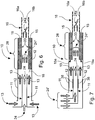
- Figures 6 and 7 show schematic examples of how the flows 13, 24 can be brought to the filter structure 10 and thus also to the flow channel 18.
- the figure shows schematically the analyser 16 that comes after the filter structure 10.
- the gas flows 13, 24 can be brought to the structure 10 from different sides of it, or even from the same side, depending on the implementation.
- the mainly non-ionized gas flow 13 is formed by bringing a neutral shield-gas flow 13 to the flow channel 18. If the filter structure 10 is examined in its typical operating attitude, in which the electrodes 33 are on the upper and lower surface of the flow channel 18, the ionised flow 24 is brought to the filter structure 10 from its end, without no change in direction. The neutral flows 13 are brought to the filter structure 10 from above it and below it.
- the embodiment of Figure 7 shows an example of the embodiment, in which a narrow ion flow 24 is created by neutralizing the side flows 13. Now the gas flows to be brought to the filter structure 10 can all be the same ionized gas flow 24' brought from the ionizer and, for example, led from above to the filter structure 10 in its typical operating attitude.
- the mainly non-ionized gas flow 13 is formed by neutralizing part of the gas flow 24' only once it is in the flow channel 18.
- the structure 11 dividing the flow channel 18 into parts is fitted with electrode means 38 by means of which are arranged to neutralize part of the ionized gas flow 24' brought to the flow channel 18, to create mainly non-ionized gas flows 13.
- This embodiment has the advantage of simple implementation. When creating an ionized flow 24 and a neutral flow 13 with the aid of the structure 10, there is no need at all for 'clean' flows as shields and for bringing to the structure 10.
- the flows 24, 13 after the divider structure 11 arranged in the flow channel 18 are combined to form a single flow 24', so that the ionization flow 24 remains as its own narrow band relative to the cross-section of the channel 18, for example in the centre of the channel 18.
- a flow arrangement like that of the second order can be implemented inside the DMS/FAIMS filter 10, when neutralization of the passage mobility will be reduced and the signal-noise ratio will improve.
- the flows can be arranged as shown in the figures and in such a way as to preserve the ionization zone 26, unless it is separately disturbed.
- Figures 6 and 7 show schematically the flight 24a of ions in an analyser 16 in an electric field set for measurement. This does not affect the flow profile, as the concentration is non-existent relative to the mass flow.
- a measurement field is created, or measurement is performed, using electrodes 16a and these have a counter electrode 16b.
- a mobility analysis of the ions is made, i.e. different mobilities are directed to different electrodes by using either a permanent electric field, or by varying the magnitude of the electric field in such a way as to change the so-called boundary mobility coming to the electrode.
- Figure 8 shows a further few examples of the dimensions, or dimension ratios of the structure 10.
- the length L DMS of the DMS electrodes 33, i.e. of the area 28, in the flow direction, i.e. the longitudinal direction of the structure 10, can be, for example 10 - 80 mm.
- the height D of the flow channel 18 can be, for example, 1 - 10 mm.
- the thickness W of the throttle structures 15 of the whole height H of the flow channel 18 can be, for example, 25 - 75%.
- the height S of the sub-flow channels formed by the divider structures 11 can be, for example, 0.1 - 2 mm.
- the ratio between the height D of the flow channel 18 and the sub-channels can be D > 3S, but, however, preferably D ⁇ 10S.
- the thickness W of the throttle structures 15 in the area of the DMS/FAIMS electrodes 33 can be 50 - 90% of the height S of the side-flow channels.
- the throttle plates 15 narrow the filter area 28 on the entry side, which flattens the combined flow 24* after the divider structures 11.
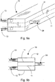
- Figures 9a and 9b show yet another, outwith the scope of the invention, of bringing the flows 13, 24 to the filter structure 10.
- Figure 9b shows a cross-section of the filter structure 10 of Figure 9a , seen from the end, from the entry point of the gas flows 13, 24 to the structure 10.
- the flows 13, 24 are brought to the filter structure 10 from the side, if the filter structure 10 is examined in its typical operating attitude, when the electrodes 33 are in the upper and lower walls 12 of the flow channel 18.
- the particular advantage of this embodiment is in the manufacture of the filter structure 10, especially when the parts of the piece 10 are made using injection moulding, or some other method that permits the entire set of channels to be made from a single part.
- the gas-flow connections can be easily arranged in the filter structure 10.
- the ionized gas flow 24 is brought from one side of the filter structure 10 to the sub-channel delimited by the wall structures 11 fitted to the flow channel 18.
- the non-ionized shield flows 13 are, for their part, brought to the filter structure 10 from the opposite side, to the under channels delimited by the wall structures 11 fitted to the flow channel 18 and the outer wall 12 of the flow channel 18.
- One other way would be to bring all the flows 13, 24 from the same side of the structure 10.
- the side flows 13 are arranged in such a way that a middle flow 24 forms the narrow and flattened part in the middle of the channel 18.
- the flows 13, 24 can be of the same magnitude (the same mass flow) in the same-sized sub-channels.
- one measure of the quality of the device 10 can be the narrowness (the narrower the better) of the flow 24 in the middle, relative to the total flow.
- the height of the side channels can be altered with the mass flows, in such a way that the flow velocities in the different channels are more or less the same. In that case, turbulence and spreading of the middle flow 24 will not take place when the flows 13, 24 combine.
- the use of single-size channels can be an optimum, in which the same mass flow produces the same velocities in all the single-size channels.
- Channels of different sizes are not, however, excluded, as in the practice device the large side-flow channels can, in some cases, be a significant advantage.
- the ratio of the flow quantities of the middle channel and the side channels can be 1:2, or even 1:200. In other words, 200 litres per minute would flow from the side channels, while 1 litre per minute would flow from the middle, but in that case, the dimensions should, of course, be quite large.
Landscapes
- Physics & Mathematics (AREA)
- Chemical & Material Sciences (AREA)
- Spectroscopy & Molecular Physics (AREA)
- Analytical Chemistry (AREA)
- Life Sciences & Earth Sciences (AREA)
- Health & Medical Sciences (AREA)
- Electrochemistry (AREA)
- Chemical Kinetics & Catalysis (AREA)
- Biochemistry (AREA)
- General Health & Medical Sciences (AREA)
- General Physics & Mathematics (AREA)
- Immunology (AREA)
- Pathology (AREA)
- Other Investigation Or Analysis Of Materials By Electrical Means (AREA)
Description
- The present invention relates to a method for chemical analysis, in which
- a gas flow is ionized in order to form an ionized gas flow that is brought to a flow channel,
- the ionized gas flow is led to a planar filter structure fitted to the flow channel,
- the ionized gas flow is filtered using the DMS/FAIMS method, in order to remove at least some of the ions from the ionized gas flow,
-
Figure 1 shows an idealized diagram of the principle of the known FAIMS (Field Asymmetric-waveform Ion-Mobility Spectrometry) aka DMS (Differential Mobility Spectrometry) ion-filtering technique. It is used, for example, to separate different types of ions in a gaseous form. The technique is based on using a high-frequency variable electric field in the ion-filter structure. The filter structure consists of, for example, asubstrate 102 arranged to form aflow channel 18 andplanar filter electrodes 103 arranged on it facing each other. - The structure permits the passage of
only ions 104 that behave in a specific manner in an electric field and filtersother ions 105 by neutralizing them electrically. The neutralization removes the ions, because the terminal velocity received by the ions in the electric field depends on the field's strength. In an asymmetrical field, the ions oscillate in the filter at an asymmetrical velocity, which causes a net transfer of ions towards the electrodes in an advantageous direction relative to the field. The electrical-field-dependence of the ions is very small and this difference can be compensated by increasing the DC component CV to the frequency-changing field, which cancels a specific type of field dependence. - By arranging the ion-transporting gas flow between two
parallel electrodes 103, and setting an electrical field of the type referred to above between these electrodes, some of theions 105 can be removed through the structure thus obtained and the desired passband can be selected with the aid of the aforementioned compensation voltage. By using an electric field after the filter in the flow direction to collect theions 104 that have passed through the filter, it is possible to determine the quality and/or number (reference number 16 inFigures 1 and6 - 8 ) of theions 104 that have passed through. - For its part,
Figure 2 shows a situation corresponding more to reality in the case of the behaviour of the ions in the aforementioned filtering technique. Theflow profile 101 of the gas flow shows that the ionized gas flow to be analysed covers the entire cross-section area of theflow channel 18. As the ions are distributed evenly over theflow channel 18, thefilter electrodes 103 will inevitably also collections 104b that it is particularly desired to pass through the filter. Theseions 104b, which are too close to the edge of theflow channel 18, are neutralized and thus out of the flow that has passed through the filter. This reduces the signal obtained from the system comprising the filter, and also the signal-noise ratio. - Containment gas to achieve ion concentration toward the center of the flow path in FAIMS is known from
WO 2006/060807 . - The present invention is intended to create a method and structure, which will improve the signal obtained from chemical analysis. The characteristic features of the method according to the invention are stated in Claim 1 and those of the structure in Claim 6.
- In the invention, a parallel mainly non-ionic gas flow, which is on at least one side of the ionized gas flow, is led along with the ionized gas flow to the filter structure. The use of the solution prevents, or at least reduces, the filtering of ions that it is wished to pass through the filtering. In addition to the measurement signal obtained, the signal-noise ratio of the measurement signal in chemical analysis is also improved.
- According to one embodiment, the ionized gas flow can be led to the planar filter structure between a mainly non-ionized gas flow. In this case, the non-ionized gas flow is formed on both sides of the ionized gas flow, so that the flows create a kind of sandwich structure. Ion filtering implemented using the DMS/FAIMS principle can thus be operated in the so-called second-order manner.
- According to one embodiment, the ionized gas flow can also be flattened by the mainly non-ionized gas flow before both are led to the planar filter structure. In this way, the performance of the filtering can be further improved.
- By means of the invention, it is possible to solve, for example, a problem relating to planar DMS/FAIMS filtering, in which some of the ions in the air or gas flowing in the flow channel of the filter structure are so close to the edge of the flow channel that they end up on the DMS/FAIMS collection electrodes, even though they should not. By using the shield flow according to the invention, for example on both sides of the ion flow in which one is interested, as a kind of sandwich structure, only the ions to be filtered end up on the collection electrodes and are neutralized, whereas the desired ions passing through the filter remain advantageously in the middle of the flow channel. Thus, stated generally, the invention is the use of a shield flow as a factor preserving the signal, i.e. improving the signal-noise ratio. The actual measurement signal can be measured only outside the DMS filter and after it, in one way or another. The other characteristic features of the invention and other advantages achieved with the invention, are examined in more extensively in the description portion.
- In the following, the invention, which is not restricted to the embodiments disclosed hereinafter, is described in greater detail with reference to the accompanying figures, in which
- Figure 1
- shows a schematic diagram of the principle of DMS/FAIMS filtering, in an ideal situation,
- Figure 2
- shows a schematic diagram of drawbacks in the operation of a filter according to the prior art, and the behaviour of ions in it,
- Figure 3
- shows a rough schematic diagram of the operating principle of the filtering structure according to the invention, and the behaviour of ions in it,
- Figure 4
- shows schematically one construction of the filter
- Figure 5
- shows schematically a second construction of the filter,
- Figures 6 and 7
- show a few ways of bringing the flows to the filter structure,
- Figure 8
- shows examples of the dimensions of one filter structure, and
- Figures 9a and 9b
- show yet a third way to bring the flows to the filter structure.
- In the following, the method according to the invention for chemical analysis is described with reference to
Figures 3 - 7 . The term chemical analysis can refer to, for example, the qualitative and/or quantitative detection from a gas flow of substances or similar structural units in the gas flow. An aerosol, in which particles are suspended in a gas, can also be considered to be a gas flow within the context of the invention. -
Figure 3 shows schematically on a very rough level an example of the solution consistent with the invention and the behaviour of the ions in afilter structure 10. The so-called second-order solution is based on the idea of taking a planar ionizedgas flow 24 to aplanar filtering area 28 at one edge of or in the middle of aflow channel 18. In other words, the ionizedgas flow 24, which is the object of the filtering, is narrower in relation to the height of thewhole flow channel 18. - A description of the method can start, for example, from the ionization of the gas flow to be analysed. Ionization can take place, for example, outside the
flow channel 18, in which case the ions are brought from the actual source to theflow channel 18 along with the gas flow. Ionization of the gas flow can be performed, for example, in some manner of the prior art that is, as such known, or is still under development. Some nonlimiting examples are a radioactive ionizer, a corona charger, the electrospray technique, or some other well-known method. The distance from the ionizer (not shown) to the entry opening of the flow-channel structure 18 is set to be relatively short, to reduce losses. - Next, the ionized
gas flow 24 is led to theflow channel 18 forming thefilter structure 10. A parallel, mainlynon-ionized gas flow 13 is formed on at least one side of the ionizedgas flow 24 inside theactual flow channel 18. In any event, the parallel, mainlynon-ionized gas flow 13 is formed before the ionizedgas flow 24 is taken to filtering in thefiltering area 28. Thus, in the invention, thegas flow 24 to be analysed is formed from a part flow that is narrower relative to the height of theflow channel 18. In this way, a kind of 'shield flow' 13 is created on at least one side of the ionizedgas flow 24, in the flow direction between thegas flow 24 and thewall 12 of theflow channel 18. The use of theshield flow 13 makes it possible, for example, to reduce the neutralization of theedge ions 25 of theion flow 24 that is intended for later analysis. -
Figure 3 shows theflow zones non-ionized flows 13 are on both sides relative to the ionizedflow 24. Thus theflows flow flow channel 18 planarly into parts, before thefiltering area 28. - Next, the ionized
gas flow 24 is led to thefiltering area 28 arranged in theflow channel 18, in which the desired ions are filter out of it. The parallel, mainlynon-ionized gas flow 13, which is on at least one side of the ionizedgas flow 24, is led to thefiltering area 28 along with the ionizedgas flow 24. In this case, the ionizedgas flow 24 is led to thefiltering area 28 in between the mainlynon-ionized gas flow 13, which is thus on both sides of the ionizedgas flow 24. - Next, the ionized
gas flow 24 is filtered using the DMS/FAIMS method to remove at least some of theions 105 from thegas flow 24. As such, in terms of the electric fields used in it, the implementation of the DMS/FAIMS filtering will be obvious to one skilled in the art, and for this reason will not be dealt with further in this connection. In the filtering, theions 25 intended to be filtered out of the ionizedgas flow 24 arranged in the middle move in thefiltering area 28 through thepassage zones 27 formed by the shield flows 13 at the edges of theflow channel 18 and are neutralized, because their field dependence causes them to move towards thefilter electrodes 33. For its part, theions 14 of thegas flow 24 passing the filtering have not time to move to thefilter electrodes 33. In the middle of theflow channel 18 there is anoscillation zone 26 for the passingions 14, which do not end up on the filtering area's 28electrodes 33 in thefiltering area 28. -
Figures 4 - 7 show, in a roughly simplified form, some schematic structural solutions for implementing afilter structure 10 for chemical analysis, as cross-sections of theflow channel 18 in its longitudinal, i.e. flow direction. Thestructure 10 includes a flow-channel arrangement 18 for the ionizedgas flow 24. Thegas flow 24 is arranged to be filtered in thestructure 10 using the DMS/FAIMS method in aplanar filtering area 28 fitted to theflow channel 18. Thefiltering area 28 includes two DMS/FAIMS electrodes 33, which can be controlled in a manner that is, as such, known, using known control means (not shown). Thestructure 10 includesmeans 11 for creating a mainlynon-ionized gas flow 13 on at least one side of the ionizedgas flow 24. - In the embodiment shown in
Figure 4 , themeans 11 include astructure 11 dividing thegas flow 18 into parts before thefiltering area 28. By means of thestructure 11, several narrower flow channels, whose height is only part of the height of theentire flow channel 18, are formed in theflow channel 18. By means of thestructure 11, the ionizedgas flow 24 intended to be analysed can be arranged in the middle of theflow channel 18, with the mainly non-ionized, i.e. neutral gas flows 13 on both sides relative to it. By means of thechannel structure 11, the neutral, i.e. shield-flows 13 are kept separate from the ionizedflow 24 in the middle. - In the embodiments of
Figures 4 - 7 , thestructure 10 includes twolongitudinal walls 11 in the direction of theflow channel 18 fitted to theflow channel 18. Thewalls 11 too are planar. - The mainly
non-ionized gas flow 13 and the ionizedgas flow 24 are combined with each other before they are led to thefiltering area 28. For this purpose asmall gap 19 is arranged to remain that is free of the dividingstructures 11, between thestructure 11 dividing theflow channel 18 into parts and thefiltering area 28. Of course, thenon-ionized gas flow 13 and the ionizedgas flow 24 can be combined with each other already when they are brought to theflow channel 18, but they may then mix with each other detrimentally before thefiltering area 28 to such an extent as to impair the result of the filtering. -
Figures 5 - 7 show a second embodiment of thefilter structure 10. In it the mainlynon-ionized gas flow 13 is used to flatten the ionizedgas flow 24 on both sides, when they are led to thefiltering area 28. One way to implement this is to arrange athrottle structure 15 in thefiltering area 28 in order to flatten the ionizedgas flow 24 using the mainlynon-ionized gas flow 13. Thestructure 15 is now implemented by means of a material layer fitted over the entire length of thefiltering area 28, which reduces the height of theflow channel 18 in thefiltering area 28. Thestructure 15 is in asubstrate 12 on opposite edges of theflow channel 18. For their part, the DMS/FAIMS electrodes 33 are now on the surfaces of thematerial layer 15 opposite each other. - The structure-
free gap 19 remaining between thedivider structure 11 and thefiltering area 28 now permits the side flows 13 to turn and the combinedflow 24* will fit to go to thefiltering area 28. The flattening of theeffective flow 24 in the middle, achieved by the turning of the side flows 13, improves performance. The entry-side edge 15a of thethrottle structure 15 is vertical. Optimally, however, these shapes can be slightly curved or bevelled, so that the sharp corners will not cause problems. -
Figures 6 and 7 show schematic examples of how theflows filter structure 10 and thus also to theflow channel 18. In addition, the figure shows schematically theanalyser 16 that comes after thefilter structure 10. The gas flows 13, 24 can be brought to thestructure 10 from different sides of it, or even from the same side, depending on the implementation. - In the structure of
Figure 6 , the mainlynon-ionized gas flow 13 is formed by bringing a neutral shield-gas flow 13 to theflow channel 18. If thefilter structure 10 is examined in its typical operating attitude, in which theelectrodes 33 are on the upper and lower surface of theflow channel 18, the ionisedflow 24 is brought to thefilter structure 10 from its end, without no change in direction. The neutral flows 13 are brought to thefilter structure 10 from above it and below it. The embodiment ofFigure 7 shows an example of the embodiment, in which anarrow ion flow 24 is created by neutralizing the side flows 13. Now the gas flows to be brought to thefilter structure 10 can all be the same ionized gas flow 24' brought from the ionizer and, for example, led from above to thefilter structure 10 in its typical operating attitude. In this case, the mainlynon-ionized gas flow 13 is formed by neutralizing part of the gas flow 24' only once it is in theflow channel 18. To neutralize the side flows 13, thestructure 11 dividing theflow channel 18 into parts is fitted with electrode means 38 by means of which are arranged to neutralize part of the ionized gas flow 24' brought to theflow channel 18, to create mainly non-ionized gas flows 13. This embodiment has the advantage of simple implementation. When creating an ionizedflow 24 and aneutral flow 13 with the aid of thestructure 10, there is no need at all for 'clean' flows as shields and for bringing to thestructure 10. - In both structures, the
flows divider structure 11 arranged in theflow channel 18 are combined to form a single flow 24', so that theionization flow 24 remains as its own narrow band relative to the cross-section of thechannel 18, for example in the centre of thechannel 18. A flow arrangement like that of the second order can be implemented inside the DMS/FAIMS filter 10, when neutralization of the passage mobility will be reduced and the signal-noise ratio will improve. In a structure according to the invention like that of the second order, the flows can be arranged as shown in the figures and in such a way as to preserve theionization zone 26, unless it is separately disturbed. -
Figures 6 and 7 show schematically theflight 24a of ions in ananalyser 16 in an electric field set for measurement. This does not affect the flow profile, as the concentration is non-existent relative to the mass flow. A measurement field is created, or measurement is performed, usingelectrodes 16a and these have acounter electrode 16b. Using the electrodes, for example a mobility analysis of the ions is made, i.e. different mobilities are directed to different electrodes by using either a permanent electric field, or by varying the magnitude of the electric field in such a way as to change the so-called boundary mobility coming to the electrode. -
Figure 8 shows a further few examples of the dimensions, or dimension ratios of thestructure 10. The length LDMS of theDMS electrodes 33, i.e. of thearea 28, in the flow direction, i.e. the longitudinal direction of thestructure 10, can be, for example 10 - 80 mm. The height D of theflow channel 18 can be, for example, 1 - 10 mm. The thickness W of thethrottle structures 15 of the whole height H of theflow channel 18 can be, for example, 25 - 75%. The height S of the sub-flow channels formed by thedivider structures 11 can be, for example, 0.1 - 2 mm. The ratio between the height D of theflow channel 18 and the sub-channels can be D > 3S, but, however, preferably D < 10S. - The thickness W of the
throttle structures 15 in the area of the DMS/FAIMS electrodes 33 can be 50 - 90% of the height S of the side-flow channels. Thethrottle plates 15 narrow thefilter area 28 on the entry side, which flattens the combinedflow 24* after thedivider structures 11. -
Figures 9a and 9b show yet another, outwith the scope of the invention, of bringing theflows filter structure 10.Figure 9b shows a cross-section of thefilter structure 10 ofFigure 9a , seen from the end, from the entry point of the gas flows 13, 24 to thestructure 10. In this embodiment, theflows filter structure 10 from the side, if thefilter structure 10 is examined in its typical operating attitude, when theelectrodes 33 are in the upper andlower walls 12 of theflow channel 18. The particular advantage of this embodiment is in the manufacture of thefilter structure 10, especially when the parts of thepiece 10 are made using injection moulding, or some other method that permits the entire set of channels to be made from a single part. When the gas flows 13, 24 are brought to thefilter structure 10 in this way, the gas-flow connections can be easily arranged in thefilter structure 10. - The ionized
gas flow 24 is brought from one side of thefilter structure 10 to the sub-channel delimited by thewall structures 11 fitted to theflow channel 18. The non-ionized shield flows 13 are, for their part, brought to thefilter structure 10 from the opposite side, to the under channels delimited by thewall structures 11 fitted to theflow channel 18 and theouter wall 12 of theflow channel 18. One other way would be to bring all theflows structure 10. - The side flows 13 are arranged in such a way that a
middle flow 24 forms the narrow and flattened part in the middle of thechannel 18. According to one embodiment, theflows device 10 can be the narrowness (the narrower the better) of theflow 24 in the middle, relative to the total flow. The height of the side channels can be altered with the mass flows, in such a way that the flow velocities in the different channels are more or less the same. In that case, turbulence and spreading of themiddle flow 24 will not take place when theflows - It must be understood that the above description and the related figures are only intended to illustrate the present invention. The invention is thus in no way restricted to only the embodiments disclosed or stated in the Claims, but many different variations and adaptations of the invention, which are possible within the scope on the inventive idea defined in the accompanying Claims, will be obvious to one skilled in the art.
Claims (9)
- Method for chemical analysis, in which- a gas flow is ionized in order to form an ionized gas flow (24', 24) that is brought to a flow channel (18),- the ionized gas flow (24) is led to a filtering area (28) fitted to the flow channel (18),- the ionized gas flow (24) is filtered using the DMS/FAIMS method, in order to remove at least some of the ions (25, 105) from the ionized gas flow (24), a mainly non-ionized gas flow (13), which is on at least one side of the ionized gas flow (24), is led to the filtering area (28) together with the ionized gas flow (24),characterized in that- part of the ionized gas flow (24') is neutralized within the flow channel (18) in order to form said mainly non-ionized gas flow (13),- wherein said mainly non-ionized gas flow (13) is parallel.
- Method according to Claim 1, characterized in that the ionized gas flow (24) is led to the filtering area (28) between the mainly non-ionized gas flow (13).
- Method according to Claim 1 or 2, characterized in that the mainly non-ionized gas flow (13) and the ionized gas flow (24) are combined with each other before being led to the filtering area (28).
- Method according to any of Claims 1 - 3, characterized in that the ionized gas flow (24) is flattened by the mainly non-ionized gas flow (13) when they are led to the filtering area (28) .
- Method according to any of Claims 1 - 4, characterized in that at least part of the gas flow (13, 24) is brought from the sides into the filtering structure (10), when it is in the operating attitude.
- Structure for chemical analysis, which includes a flow-channel arrangement (18) for an ionized gas flow (24), which is arranged to be filtered using the DMS/FAIMS method in a planar filtering area (28) fitted to the flow channel (18), wherein the structure includes means for creating a mainly non-ionized gas flow (13) on at least one side of the ionized gas flow (24) which means include a structure (11) dividing the flow channel (18) into parts, in the middle of which can be arranged the ionized gas flow (24), with the mainly non-ionized gas flowing (13) on both sides characterized in that said structure (11) dividing the flow channel (18) into parts includes electrode means (38) arranged to neutralize part of the ionized gas flow (24') brought to the flow channel (18) in order to create the mainly non-ionized gas flow (13).
- Structure according to Claim 6, characterized in that a gap (19) is arranged to remain between the structure (11) dividing the flow channel (18) into parts and the filtering area (28).
- Structure according to Claim 6 or 7, characterized in that the filtering area (28) includes a structure (15) for flattening the ionized gas flow (24) by the mainly non-ionized gas flow (13).
- Structure according to any of Claims 6 - 8, characterized in that at least part of the gas flows (13, 24, 24') is arranged to be brought from the sides into the filter structure (10) when it is in the operating attitude.
Applications Claiming Priority (2)
| Application Number | Priority Date | Filing Date | Title |
|---|---|---|---|
| FI20125440 | 2012-04-23 | ||
| PCT/FI2013/050440 WO2013160543A1 (en) | 2012-04-23 | 2013-04-19 | Method and structure for chemical analysis |
Publications (3)
| Publication Number | Publication Date |
|---|---|
| EP2841934A1 EP2841934A1 (en) | 2015-03-04 |
| EP2841934A4 EP2841934A4 (en) | 2016-01-06 |
| EP2841934B1 true EP2841934B1 (en) | 2019-04-03 |
Family
ID=49482266
Family Applications (1)
| Application Number | Title | Priority Date | Filing Date |
|---|---|---|---|
| EP13781756.5A Active EP2841934B1 (en) | 2012-04-23 | 2013-04-19 | Method and structure for chemical analysis |
Country Status (17)
| Country | Link |
|---|---|
| US (1) | US20150293059A1 (en) |
| EP (1) | EP2841934B1 (en) |
| JP (1) | JP6197028B2 (en) |
| KR (1) | KR20150012250A (en) |
| CN (1) | CN104246490B (en) |
| AU (1) | AU2013254543A1 (en) |
| CA (1) | CA2869520A1 (en) |
| DK (1) | DK2841934T3 (en) |
| ES (1) | ES2728909T3 (en) |
| IL (1) | IL234932B (en) |
| IN (1) | IN2014DN09820A (en) |
| MX (1) | MX360123B (en) |
| PH (1) | PH12014502126B1 (en) |
| RU (1) | RU2622480C2 (en) |
| SG (1) | SG11201406784YA (en) |
| TR (1) | TR201909601T4 (en) |
| WO (1) | WO2013160543A1 (en) |
Families Citing this family (2)
| Publication number | Priority date | Publication date | Assignee | Title |
|---|---|---|---|---|
| JP2020020746A (en) * | 2018-08-03 | 2020-02-06 | 株式会社リコー | Detector |
| CN112687516B (en) * | 2020-12-21 | 2022-03-29 | 清华大学 | Multi-channel high-field asymmetric waveform ion mobility tube |
Family Cites Families (20)
| Publication number | Priority date | Publication date | Assignee | Title |
|---|---|---|---|---|
| US4023398A (en) * | 1975-03-03 | 1977-05-17 | John Barry French | Apparatus for analyzing trace components |
| US5247842A (en) * | 1991-09-30 | 1993-09-28 | Tsi Incorporated | Electrospray apparatus for producing uniform submicrometer droplets |
| US5922976A (en) * | 1995-10-12 | 1999-07-13 | California Institute Of Technology | Method of measuring aerosol particles using automated mobility-classified aerosol detector |
| US6512224B1 (en) * | 1999-07-21 | 2003-01-28 | The Charles Stark Draper Laboratory, Inc. | Longitudinal field driven field asymmetric ion mobility filter and detection system |
| US6815668B2 (en) * | 1999-07-21 | 2004-11-09 | The Charles Stark Draper Laboratory, Inc. | Method and apparatus for chromatography-high field asymmetric waveform ion mobility spectrometry |
| RU2178929C2 (en) * | 2000-01-25 | 2002-01-27 | Конструкторско-технологический институт геофизического и экологического приборостроения СО РАН | Spectrometer of non-linearity of drift of ions |
| US6998608B2 (en) * | 2002-02-08 | 2006-02-14 | Ionalytics Corporation | FAIMS with non-destructive detection of selectively transmitted ions |
| US7358504B2 (en) * | 2002-09-25 | 2008-04-15 | Thermo Finnigan Llc | FAIMS apparatus and method for separating ions |
| AU2003291523A1 (en) * | 2002-11-22 | 2004-06-18 | The Regents Of The University Of California | Method and apparatus for performing ion mobility spectrometry |
| US7399959B2 (en) | 2004-12-03 | 2008-07-15 | Sionex Corporation | Method and apparatus for enhanced ion based sample filtering and detection |
| US8754366B2 (en) * | 2005-01-11 | 2014-06-17 | Hamilton Sundstrand Corporation | Tandem differential mobility ion mobility spectrometer for chemical vapor detection |
| DE102005007746B4 (en) * | 2005-02-18 | 2009-01-08 | Dräger Safety AG & Co. KGaA | Ion mobility spectrometer with parallel drift gas and ion carrier gas flow |
| DE102005031048A1 (en) * | 2005-07-02 | 2007-01-04 | Dräger Safety AG & Co. KGaA | Ion mobility spectrometer uses unidirectional drift with larger dominant drift gas flow before detector electrode in separation area |
| JP2007033064A (en) * | 2005-07-22 | 2007-02-08 | Institute Of Physical & Chemical Research | Fine particle counter |
| GB2441943A (en) * | 2005-07-26 | 2008-03-19 | Sionex Corp | Ultra compact ion mobility based analyzer system and method |
| CN101688848A (en) * | 2007-02-05 | 2010-03-31 | 卓漂仪谱公司 | Methods and apparatus of ion mobility spectrometer |
| CN101067616B (en) * | 2007-06-06 | 2011-07-20 | 中国科学院合肥物质科学研究院 | Longitudinal high-field asymmetrical wave form ion mobility spectrum device |
| FI123930B (en) * | 2008-04-03 | 2013-12-31 | Environics Oy | Method for measuring gases |
| US20100282966A1 (en) * | 2008-05-30 | 2010-11-11 | DH Technologies Development Pte Ltd. | Method and system for vacuum driven mass spectrometer interface with adjustable resolution and selectivity |
| JP5579706B2 (en) * | 2008-05-30 | 2014-08-27 | ディーエイチ テクノロジーズ デベロップメント プライベート リミテッド | Method and system for providing a regulator to a curtain gas for a differential mobility spectrometer |
-
2013
- 2013-04-19 KR KR1020147031419A patent/KR20150012250A/en not_active Application Discontinuation
- 2013-04-19 ES ES13781756T patent/ES2728909T3/en active Active
- 2013-04-19 CA CA2869520A patent/CA2869520A1/en not_active Abandoned
- 2013-04-19 EP EP13781756.5A patent/EP2841934B1/en active Active
- 2013-04-19 RU RU2014147025A patent/RU2622480C2/en active
- 2013-04-19 CN CN201380021376.4A patent/CN104246490B/en active Active
- 2013-04-19 MX MX2014012809A patent/MX360123B/en active IP Right Grant
- 2013-04-19 SG SG11201406784YA patent/SG11201406784YA/en unknown
- 2013-04-19 WO PCT/FI2013/050440 patent/WO2013160543A1/en active Application Filing
- 2013-04-19 DK DK13781756.5T patent/DK2841934T3/en active
- 2013-04-19 JP JP2015506273A patent/JP6197028B2/en active Active
- 2013-04-19 AU AU2013254543A patent/AU2013254543A1/en not_active Abandoned
- 2013-04-19 US US14/388,267 patent/US20150293059A1/en not_active Abandoned
- 2013-04-19 TR TR2019/09601T patent/TR201909601T4/en unknown
-
2014
- 2014-09-24 PH PH12014502126A patent/PH12014502126B1/en unknown
- 2014-10-02 IL IL234932A patent/IL234932B/en active IP Right Grant
- 2014-11-19 IN IN9820DEN2014 patent/IN2014DN09820A/en unknown
Non-Patent Citations (1)
| Title |
|---|
| None * |
Also Published As
| Publication number | Publication date |
|---|---|
| RU2014147025A (en) | 2016-06-10 |
| AU2013254543A1 (en) | 2014-11-06 |
| CA2869520A1 (en) | 2013-10-31 |
| RU2622480C2 (en) | 2017-06-15 |
| IL234932B (en) | 2018-08-30 |
| MX2014012809A (en) | 2015-01-22 |
| DK2841934T3 (en) | 2019-06-17 |
| MX360123B (en) | 2018-10-22 |
| EP2841934A4 (en) | 2016-01-06 |
| IN2014DN09820A (en) | 2015-07-31 |
| TR201909601T4 (en) | 2019-07-22 |
| PH12014502126A1 (en) | 2014-12-10 |
| JP2015514989A (en) | 2015-05-21 |
| EP2841934A1 (en) | 2015-03-04 |
| JP6197028B2 (en) | 2017-09-13 |
| KR20150012250A (en) | 2015-02-03 |
| US20150293059A1 (en) | 2015-10-15 |
| ES2728909T3 (en) | 2019-10-29 |
| CN104246490B (en) | 2016-10-12 |
| CN104246490A (en) | 2014-12-24 |
| SG11201406784YA (en) | 2014-11-27 |
| PH12014502126B1 (en) | 2014-12-10 |
| WO2013160543A1 (en) | 2013-10-31 |
Similar Documents
| Publication | Publication Date | Title |
|---|---|---|
| CN103650102B (en) | Ion migration spectrometer, include its gas analysis system and the method determining chemical race | |
| TWI484172B (en) | Process and device for the identification of gases | |
| US10139367B2 (en) | Ion mobility spectrometer with ion modification | |
| EP2850641B1 (en) | Control of gas flow in high field asymmetric waveform ion mobility spectrometry | |
| EP2428797B1 (en) | Device for identifying and detecting gases by means of ion mobility spectrometry | |
| US20160203967A1 (en) | Ion modification | |
| WO2011094529A3 (en) | Mass analysis system with low pressure differential mobility spectrometer | |
| US20170108480A1 (en) | Detector inlet and sampling method | |
| CN101999156B (en) | Method for measuring gases and corresponding ion mobility spectrometer | |
| US20100200745A1 (en) | Ion gate method and apparatus | |
| EP2841934B1 (en) | Method and structure for chemical analysis | |
| US9835588B2 (en) | Jet injector inlet for a differential mobility spectrometer | |
| CA2915927C (en) | Detectors and ion sources | |
| CA2525095A1 (en) | Ion mobility separation devices | |
| CA2634880A1 (en) | Faims cell having an offset ion inlet orifice | |
| CN207068790U (en) | A kind of BN types ion gate | |
| WO2012167254A1 (en) | Method and system for reducing interferences in the spectrometric analysis of steroids | |
| US20190323930A1 (en) | Method for determining concentrated form of analyte and method for converting concentrated form of analyte |
Legal Events
| Date | Code | Title | Description |
|---|---|---|---|
| PUAI | Public reference made under article 153(3) epc to a published international application that has entered the european phase |
Free format text: ORIGINAL CODE: 0009012 |
|
| 17P | Request for examination filed |
Effective date: 20141105 |
|
| AK | Designated contracting states |
Kind code of ref document: A1 Designated state(s): AL AT BE BG CH CY CZ DE DK EE ES FI FR GB GR HR HU IE IS IT LI LT LU LV MC MK MT NL NO PL PT RO RS SE SI SK SM TR |
|
| AX | Request for extension of the european patent |
Extension state: BA ME |
|
| DAX | Request for extension of the european patent (deleted) | ||
| RA4 | Supplementary search report drawn up and despatched (corrected) |
Effective date: 20151203 |
|
| RIC1 | Information provided on ipc code assigned before grant |
Ipc: G01N 27/62 20060101AFI20151127BHEP |
|
| STAA | Information on the status of an ep patent application or granted ep patent |
Free format text: STATUS: EXAMINATION IS IN PROGRESS |
|
| 17Q | First examination report despatched |
Effective date: 20180614 |
|
| GRAP | Despatch of communication of intention to grant a patent |
Free format text: ORIGINAL CODE: EPIDOSNIGR1 |
|
| STAA | Information on the status of an ep patent application or granted ep patent |
Free format text: STATUS: GRANT OF PATENT IS INTENDED |
|
| GRAJ | Information related to disapproval of communication of intention to grant by the applicant or resumption of examination proceedings by the epo deleted |
Free format text: ORIGINAL CODE: EPIDOSDIGR1 |
|
| INTG | Intention to grant announced |
Effective date: 20180831 |
|
| RIN1 | Information on inventor provided before grant (corrected) |
Inventor name: ANTTALAINEN, OSMO |
|
| STAA | Information on the status of an ep patent application or granted ep patent |
Free format text: STATUS: EXAMINATION IS IN PROGRESS |
|
| GRAP | Despatch of communication of intention to grant a patent |
Free format text: ORIGINAL CODE: EPIDOSNIGR1 |
|
| STAA | Information on the status of an ep patent application or granted ep patent |
Free format text: STATUS: GRANT OF PATENT IS INTENDED |
|
| INTC | Intention to grant announced (deleted) | ||
| INTG | Intention to grant announced |
Effective date: 20181031 |
|
| GRAS | Grant fee paid |
Free format text: ORIGINAL CODE: EPIDOSNIGR3 |
|
| GRAA | (expected) grant |
Free format text: ORIGINAL CODE: 0009210 |
|
| STAA | Information on the status of an ep patent application or granted ep patent |
Free format text: STATUS: THE PATENT HAS BEEN GRANTED |
|
| AK | Designated contracting states |
Kind code of ref document: B1 Designated state(s): AL AT BE BG CH CY CZ DE DK EE ES FI FR GB GR HR HU IE IS IT LI LT LU LV MC MK MT NL NO PL PT RO RS SE SI SK SM TR |
|
| REG | Reference to a national code |
Ref country code: GB Ref legal event code: FG4D |
|
| REG | Reference to a national code |
Ref country code: CH Ref legal event code: EP Ref country code: AT Ref legal event code: REF Ref document number: 1116361 Country of ref document: AT Kind code of ref document: T Effective date: 20190415 |
|
| REG | Reference to a national code |
Ref country code: DE Ref legal event code: R096 Ref document number: 602013053349 Country of ref document: DE |
|
| REG | Reference to a national code |
Ref country code: IE Ref legal event code: FG4D |
|
| REG | Reference to a national code |
Ref country code: DK Ref legal event code: T3 Effective date: 20190613 |
|
| REG | Reference to a national code |
Ref country code: NL Ref legal event code: FP |
|
| REG | Reference to a national code |
Ref country code: LT Ref legal event code: MG4D |
|
| REG | Reference to a national code |
Ref country code: AT Ref legal event code: MK05 Ref document number: 1116361 Country of ref document: AT Kind code of ref document: T Effective date: 20190403 |
|
| REG | Reference to a national code |
Ref country code: ES Ref legal event code: FG2A Ref document number: 2728909 Country of ref document: ES Kind code of ref document: T3 Effective date: 20191029 |
|
| PG25 | Lapsed in a contracting state [announced via postgrant information from national office to epo] |
Ref country code: PT Free format text: LAPSE BECAUSE OF FAILURE TO SUBMIT A TRANSLATION OF THE DESCRIPTION OR TO PAY THE FEE WITHIN THE PRESCRIBED TIME-LIMIT Effective date: 20190803 Ref country code: HR Free format text: LAPSE BECAUSE OF FAILURE TO SUBMIT A TRANSLATION OF THE DESCRIPTION OR TO PAY THE FEE WITHIN THE PRESCRIBED TIME-LIMIT Effective date: 20190403 Ref country code: SE Free format text: LAPSE BECAUSE OF FAILURE TO SUBMIT A TRANSLATION OF THE DESCRIPTION OR TO PAY THE FEE WITHIN THE PRESCRIBED TIME-LIMIT Effective date: 20190403 Ref country code: AL Free format text: LAPSE BECAUSE OF FAILURE TO SUBMIT A TRANSLATION OF THE DESCRIPTION OR TO PAY THE FEE WITHIN THE PRESCRIBED TIME-LIMIT Effective date: 20190403 Ref country code: NO Free format text: LAPSE BECAUSE OF FAILURE TO SUBMIT A TRANSLATION OF THE DESCRIPTION OR TO PAY THE FEE WITHIN THE PRESCRIBED TIME-LIMIT Effective date: 20190703 Ref country code: CZ Free format text: LAPSE BECAUSE OF FAILURE TO SUBMIT A TRANSLATION OF THE DESCRIPTION OR TO PAY THE FEE WITHIN THE PRESCRIBED TIME-LIMIT Effective date: 20190403 Ref country code: LT Free format text: LAPSE BECAUSE OF FAILURE TO SUBMIT A TRANSLATION OF THE DESCRIPTION OR TO PAY THE FEE WITHIN THE PRESCRIBED TIME-LIMIT Effective date: 20190403 |
|
| PG25 | Lapsed in a contracting state [announced via postgrant information from national office to epo] |
Ref country code: RS Free format text: LAPSE BECAUSE OF FAILURE TO SUBMIT A TRANSLATION OF THE DESCRIPTION OR TO PAY THE FEE WITHIN THE PRESCRIBED TIME-LIMIT Effective date: 20190403 Ref country code: LV Free format text: LAPSE BECAUSE OF FAILURE TO SUBMIT A TRANSLATION OF THE DESCRIPTION OR TO PAY THE FEE WITHIN THE PRESCRIBED TIME-LIMIT Effective date: 20190403 Ref country code: BG Free format text: LAPSE BECAUSE OF FAILURE TO SUBMIT A TRANSLATION OF THE DESCRIPTION OR TO PAY THE FEE WITHIN THE PRESCRIBED TIME-LIMIT Effective date: 20190703 Ref country code: GR Free format text: LAPSE BECAUSE OF FAILURE TO SUBMIT A TRANSLATION OF THE DESCRIPTION OR TO PAY THE FEE WITHIN THE PRESCRIBED TIME-LIMIT Effective date: 20190704 Ref country code: PL Free format text: LAPSE BECAUSE OF FAILURE TO SUBMIT A TRANSLATION OF THE DESCRIPTION OR TO PAY THE FEE WITHIN THE PRESCRIBED TIME-LIMIT Effective date: 20190403 |
|
| REG | Reference to a national code |
Ref country code: CH Ref legal event code: PL |
|
| PG25 | Lapsed in a contracting state [announced via postgrant information from national office to epo] |
Ref country code: IS Free format text: LAPSE BECAUSE OF FAILURE TO SUBMIT A TRANSLATION OF THE DESCRIPTION OR TO PAY THE FEE WITHIN THE PRESCRIBED TIME-LIMIT Effective date: 20190803 Ref country code: LU Free format text: LAPSE BECAUSE OF NON-PAYMENT OF DUE FEES Effective date: 20190419 Ref country code: AT Free format text: LAPSE BECAUSE OF FAILURE TO SUBMIT A TRANSLATION OF THE DESCRIPTION OR TO PAY THE FEE WITHIN THE PRESCRIBED TIME-LIMIT Effective date: 20190403 |
|
| REG | Reference to a national code |
Ref country code: DE Ref legal event code: R097 Ref document number: 602013053349 Country of ref document: DE |
|
| PG25 | Lapsed in a contracting state [announced via postgrant information from national office to epo] |
Ref country code: MC Free format text: LAPSE BECAUSE OF FAILURE TO SUBMIT A TRANSLATION OF THE DESCRIPTION OR TO PAY THE FEE WITHIN THE PRESCRIBED TIME-LIMIT Effective date: 20190403 Ref country code: CH Free format text: LAPSE BECAUSE OF NON-PAYMENT OF DUE FEES Effective date: 20190430 Ref country code: EE Free format text: LAPSE BECAUSE OF FAILURE TO SUBMIT A TRANSLATION OF THE DESCRIPTION OR TO PAY THE FEE WITHIN THE PRESCRIBED TIME-LIMIT Effective date: 20190403 Ref country code: LI Free format text: LAPSE BECAUSE OF NON-PAYMENT OF DUE FEES Effective date: 20190430 Ref country code: RO Free format text: LAPSE BECAUSE OF FAILURE TO SUBMIT A TRANSLATION OF THE DESCRIPTION OR TO PAY THE FEE WITHIN THE PRESCRIBED TIME-LIMIT Effective date: 20190403 Ref country code: SK Free format text: LAPSE BECAUSE OF FAILURE TO SUBMIT A TRANSLATION OF THE DESCRIPTION OR TO PAY THE FEE WITHIN THE PRESCRIBED TIME-LIMIT Effective date: 20190403 |
|
| PLBE | No opposition filed within time limit |
Free format text: ORIGINAL CODE: 0009261 |
|
| STAA | Information on the status of an ep patent application or granted ep patent |
Free format text: STATUS: NO OPPOSITION FILED WITHIN TIME LIMIT |
|
| PG25 | Lapsed in a contracting state [announced via postgrant information from national office to epo] |
Ref country code: SM Free format text: LAPSE BECAUSE OF FAILURE TO SUBMIT A TRANSLATION OF THE DESCRIPTION OR TO PAY THE FEE WITHIN THE PRESCRIBED TIME-LIMIT Effective date: 20190403 |
|
| 26N | No opposition filed |
Effective date: 20200106 |
|
| PG25 | Lapsed in a contracting state [announced via postgrant information from national office to epo] |
Ref country code: IE Free format text: LAPSE BECAUSE OF NON-PAYMENT OF DUE FEES Effective date: 20190419 |
|
| PG25 | Lapsed in a contracting state [announced via postgrant information from national office to epo] |
Ref country code: SI Free format text: LAPSE BECAUSE OF FAILURE TO SUBMIT A TRANSLATION OF THE DESCRIPTION OR TO PAY THE FEE WITHIN THE PRESCRIBED TIME-LIMIT Effective date: 20190403 |
|
| PG25 | Lapsed in a contracting state [announced via postgrant information from national office to epo] |
Ref country code: CY Free format text: LAPSE BECAUSE OF FAILURE TO SUBMIT A TRANSLATION OF THE DESCRIPTION OR TO PAY THE FEE WITHIN THE PRESCRIBED TIME-LIMIT Effective date: 20190403 |
|
| PG25 | Lapsed in a contracting state [announced via postgrant information from national office to epo] |
Ref country code: HU Free format text: LAPSE BECAUSE OF FAILURE TO SUBMIT A TRANSLATION OF THE DESCRIPTION OR TO PAY THE FEE WITHIN THE PRESCRIBED TIME-LIMIT; INVALID AB INITIO Effective date: 20130419 Ref country code: MT Free format text: LAPSE BECAUSE OF FAILURE TO SUBMIT A TRANSLATION OF THE DESCRIPTION OR TO PAY THE FEE WITHIN THE PRESCRIBED TIME-LIMIT Effective date: 20190403 |
|
| PG25 | Lapsed in a contracting state [announced via postgrant information from national office to epo] |
Ref country code: MK Free format text: LAPSE BECAUSE OF FAILURE TO SUBMIT A TRANSLATION OF THE DESCRIPTION OR TO PAY THE FEE WITHIN THE PRESCRIBED TIME-LIMIT Effective date: 20190403 |
|
| PGFP | Annual fee paid to national office [announced via postgrant information from national office to epo] |
Ref country code: FI Payment date: 20230302 Year of fee payment: 11 |
|
| PGFP | Annual fee paid to national office [announced via postgrant information from national office to epo] |
Ref country code: NL Payment date: 20230419 Year of fee payment: 11 |
|
| PGFP | Annual fee paid to national office [announced via postgrant information from national office to epo] |
Ref country code: IT Payment date: 20230426 Year of fee payment: 11 Ref country code: FR Payment date: 20230424 Year of fee payment: 11 Ref country code: ES Payment date: 20230627 Year of fee payment: 11 Ref country code: DK Payment date: 20230421 Year of fee payment: 11 Ref country code: DE Payment date: 20230420 Year of fee payment: 11 |
|
| PGFP | Annual fee paid to national office [announced via postgrant information from national office to epo] |
Ref country code: TR Payment date: 20230417 Year of fee payment: 11 |
|
| PGFP | Annual fee paid to national office [announced via postgrant information from national office to epo] |
Ref country code: BE Payment date: 20230419 Year of fee payment: 11 |
|
| PGFP | Annual fee paid to national office [announced via postgrant information from national office to epo] |
Ref country code: GB Payment date: 20230419 Year of fee payment: 11 |