EP2841753B1 - Gas turbine engine with thermal management system - Google Patents
Gas turbine engine with thermal management system Download PDFInfo
- Publication number
- EP2841753B1 EP2841753B1 EP13781579.1A EP13781579A EP2841753B1 EP 2841753 B1 EP2841753 B1 EP 2841753B1 EP 13781579 A EP13781579 A EP 13781579A EP 2841753 B1 EP2841753 B1 EP 2841753B1
- Authority
- EP
- European Patent Office
- Prior art keywords
- low pressure
- flow
- shaft
- high pressure
- rotor
- Prior art date
- Legal status (The legal status is an assumption and is not a legal conclusion. Google has not performed a legal analysis and makes no representation as to the accuracy of the status listed.)
- Active
Links
Images

Classifications
-
- F—MECHANICAL ENGINEERING; LIGHTING; HEATING; WEAPONS; BLASTING
- F02—COMBUSTION ENGINES; HOT-GAS OR COMBUSTION-PRODUCT ENGINE PLANTS
- F02C—GAS-TURBINE PLANTS; AIR INTAKES FOR JET-PROPULSION PLANTS; CONTROLLING FUEL SUPPLY IN AIR-BREATHING JET-PROPULSION PLANTS
- F02C7/00—Features, components parts, details or accessories, not provided for in, or of interest apart form groups F02C1/00 - F02C6/00; Air intakes for jet-propulsion plants
- F02C7/12—Cooling of plants
-
- F—MECHANICAL ENGINEERING; LIGHTING; HEATING; WEAPONS; BLASTING
- F01—MACHINES OR ENGINES IN GENERAL; ENGINE PLANTS IN GENERAL; STEAM ENGINES
- F01D—NON-POSITIVE DISPLACEMENT MACHINES OR ENGINES, e.g. STEAM TURBINES
- F01D5/00—Blades; Blade-carrying members; Heating, heat-insulating, cooling or antivibration means on the blades or the members
- F01D5/02—Blade-carrying members, e.g. rotors
- F01D5/08—Heating, heat-insulating or cooling means
- F01D5/081—Cooling fluid being directed on the side of the rotor disc or at the roots of the blades
- F01D5/082—Cooling fluid being directed on the side of the rotor disc or at the roots of the blades on the side of the rotor disc
-
- F—MECHANICAL ENGINEERING; LIGHTING; HEATING; WEAPONS; BLASTING
- F01—MACHINES OR ENGINES IN GENERAL; ENGINE PLANTS IN GENERAL; STEAM ENGINES
- F01D—NON-POSITIVE DISPLACEMENT MACHINES OR ENGINES, e.g. STEAM TURBINES
- F01D5/00—Blades; Blade-carrying members; Heating, heat-insulating, cooling or antivibration means on the blades or the members
- F01D5/02—Blade-carrying members, e.g. rotors
- F01D5/06—Rotors for more than one axial stage, e.g. of drum or multiple disc type; Details thereof, e.g. shafts, shaft connections
- F01D5/066—Connecting means for joining rotor-discs or rotor-elements together, e.g. by a central bolt, by clamps
-
- F—MECHANICAL ENGINEERING; LIGHTING; HEATING; WEAPONS; BLASTING
- F02—COMBUSTION ENGINES; HOT-GAS OR COMBUSTION-PRODUCT ENGINE PLANTS
- F02C—GAS-TURBINE PLANTS; AIR INTAKES FOR JET-PROPULSION PLANTS; CONTROLLING FUEL SUPPLY IN AIR-BREATHING JET-PROPULSION PLANTS
- F02C7/00—Features, components parts, details or accessories, not provided for in, or of interest apart form groups F02C1/00 - F02C6/00; Air intakes for jet-propulsion plants
- F02C7/12—Cooling of plants
- F02C7/16—Cooling of plants characterised by cooling medium
- F02C7/18—Cooling of plants characterised by cooling medium the medium being gaseous, e.g. air
-
- F—MECHANICAL ENGINEERING; LIGHTING; HEATING; WEAPONS; BLASTING
- F04—POSITIVE - DISPLACEMENT MACHINES FOR LIQUIDS; PUMPS FOR LIQUIDS OR ELASTIC FLUIDS
- F04D—NON-POSITIVE-DISPLACEMENT PUMPS
- F04D29/00—Details, component parts, or accessories
- F04D29/26—Rotors specially for elastic fluids
- F04D29/32—Rotors specially for elastic fluids for axial flow pumps
- F04D29/321—Rotors specially for elastic fluids for axial flow pumps for axial flow compressors
Definitions
- Gas turbine engines may include a low pressure compressor section 1 including a fan blade 2, a high pressure compressor section 3, a combustion section 4, a high pressure turbine section 5, and a low pressure turbine section 6.
- the high pressure compressor section 3 is connected to the high pressure turbine section by a hollow outer shaft 7 known as a tie shaft.
- the low pressure compressor section 1 is connected to the low pressure turbine section 6 by a second shaft 8, known as the low pressure shaft, which extends within the tie shaft 7.
- the compressor section 10 includes a hollow shaft 12, known as a tie shaft, which connects the compressor rotor 11 to a turbine rotor (not shown).
- the tie shaft 12 connects the high pressure rotor 11 to the high pressure turbine rotor.
- a low pressure shaft 14 located within the interior of the shaft 12 is a low pressure shaft 14 which connects a low pressure compressor rotor (not shown) to a low pressure turbine rotor (not shown) of the engine.
- the compressor rotor 11 has a plurality of disks R1 - R8 connected to the tie shaft 12. Each respective disk may carry one or more rotor blades 16. Each of the disks R1 - R8 has a rim 18. A main gas flow path 20 is formed between the rims 18 of the disks and a casing 22 which surrounds the compressor rotor 11. A plurality of bore cavities are located between the disk rims 18 and the outer diameter of the tie shaft 12. The bore cavities include forward cavities 24, 26, 28, 30, 32, and 34 and aft cavities 36, 38, and 40.
- a front hub 42 is mounted to the tie shaft 12.
- One or more flow holes 44 are provided in the front hub 42.
- a supply of cooling air is delivered to the rotor cavities 24, 26, 28, 30, 32, and 34 via the flow holes 44. Prior to being delivered to the flow holes 44, the air may be cooled using a heat exchanger 46. The cooling air passing through the flow holes 44 conditions the disk temperature and transient response as well as controls the tie shaft temperature. After passing through the forward cavities, the flow 48 of cooling air exits through one or more radial holes 50 in the tie shaft 12.
- the flow 48 of cooling air flowing through the holes 50 mixes with an intershaft flow 52 of cooling air between the tie shaft 12 and the low shaft 14.
- the intershaft flow 52 may be created in any suitable manner.
- the aft cavities 36, 38, and 40 are conditioned and may be secondarily cooled by bleeding air from the main gas path 20 via one or more radial bleed slots 56 located in a disk rim 18.
- the flow 54 of bleed air may be brought down to the rotor inner diameter using anti-vortex tubes 58 to minimize pressure loss while maximizing disk web conditioning.
- the air cavities 36, 38, and 40 are isolated from the forward cavity air by a piston ring seal 60 between the aft side of the R6 disk bore 62 and the outer diameter wall of the tie shaft 12.
- the aft cavity flow of cooling air is typically hotter and at higher pressure than the forward cavity cooling air.
- some leakage 59 of hotter aft cavity cooling air may occur under the R6 disk through the piston ring.
- the leakage 59 may join or mix with the colder forward cavity bore flow 48 prior to exiting the forward cavities through the holes 50 in the tie shaft 12.
- the majority of the flow 54 of cooling air moves aft under disk R8 and exits through an array of axial holes 66 in the foot 68 of the rear hub 69, mounted to the tie shaft 12, to form a flow 70 which flows on to a high pressure turbine (HPT)(not shown).
- HPT high pressure turbine
- the aft cavity flow 54 conditions the rotors R7 and R8 and also serves as turbine conditioning and blade cooling air. Radial gaps between the bores of rotors R1 to R8 and the tie shaft 12 may be held tight throughout all stages to enhance the heat transfer of the passing flow jet while operating sufficiently large to minimize pressure losses.
- Intershaft air flow 52 between the tie shaft 12 and the low shaft 14 may be sourced from the same cooler supply as the forward cavity air flow 48.
- the intershaft air flow 52 cools the tie shaft 12 and mixes with the forward cavity bore flow 48 coming through the holes 50 in the tie shaft 12. The mixed flow then travels aft to the low pressure turbine (LPT) section of the engine for cooling purposes.
- LPT low pressure turbine
- the outer diameter of the tie shaft 12 may be designed to favor near-straight-line forward and aft bore flows and to keep the flow at a lowest possible radius.
- the tie shaft 12 may feature thin wall barrels with wall thickness-to-radius ratios sized to prevent ovalization flutter under the air flows washing both the outer diameter and inner diameter at different velocities and axial/circumferential directions (same flow and counter flow)/clockwise and counterclockwise).
- the coupling nut 74 may be designed to have a low profile to preclude obstruction of the flow lines.
- Segregation of the forward and aft bore flows 48, 54, and 59 with an interseal 60 along with intershaft flow 52 allows optimization of the temperature and pressure of the flows to meet local high pressure compressor disk conditioning, overall tie shaft thermal expansion control, and turbine cooling requirements. This is achieved using existing rotor disk and shaft hardware to define flow/thermal zones avoiding additional disk components for the sole purpose of zone boundaries.
- the segregated aft cavities 36, 38, and 40 operate at a high pressure which provides driving force for high pressure turbine blade cooling and margin requirements.
- the radial bleed slots 56 and anti-vortex tubes 58 maximize the recoverable pressure from the source.
- Each anti-vortex tube 58 may be positioned radially to allow free vortexing of the flow near the bore and upper web 80 of the R7 and R8 disks to provide high heat transfer rapid thermal response, thereby reducing stress inducing gradients.
- the higher temperatures of the aft cavities flow source 54 and 59 are beneficial to the rear high pressure compressor disks R6 - R8 which require higher temperatures for proper conditioning.
- the cooled flow of the forward cavities 24, 26, 28, 30, 32, and 34 and the flow's direction forward-to-aft helps to match the rim temperature progression fore-to-aft as it picks up heat. This, along with the intershaft flow 52 with high heat transfer from counter-rotating walls, helps to maintain the lowest possible tie shaft temperature. This is significant in maintaining elevated preload levels in the rotor stack.
- the contoured flow guide 92 minimizes heat generation and rear hub temperature.
- Fig. 3 there is shown an alternative arrangement for the anti-vortex tubes 58.
- one anti-vortex tube 58 may be attached to the rear wall 82 of the R6 disk and a second anti-vortex tube 58' may be mounted to the front wall 84 of the R8 rotor. If desired, the tube 58' may be shorter than the tube 58.
- thermal management system for a gas turbine engine. While the thermal management system has been discussed in the context of specific embodiments thereof, other unforeseeable alternatives, variations, and modifications may become apparent to those skilled in the art. Accordingly, it is intended to embrace those alternatives, modifications, and variations which fall within the broad scope of the appended claims.
Landscapes
- Engineering & Computer Science (AREA)
- Mechanical Engineering (AREA)
- General Engineering & Computer Science (AREA)
- Chemical & Material Sciences (AREA)
- Combustion & Propulsion (AREA)
- Structures Of Non-Positive Displacement Pumps (AREA)
- Turbine Rotor Nozzle Sealing (AREA)
Description
- The present disclosure relates to a gas turbine having a thermal management system, in particular in a compressor section of the engine.
- Gas turbine engines, such as that shown in
FIG. 1 , may include a lowpressure compressor section 1 including afan blade 2, a highpressure compressor section 3, acombustion section 4, a highpressure turbine section 5, and a lowpressure turbine section 6. The highpressure compressor section 3 is connected to the high pressure turbine section by a hollowouter shaft 7 known as a tie shaft. The lowpressure compressor section 1 is connected to the lowpressure turbine section 6 by asecond shaft 8, known as the low pressure shaft, which extends within thetie shaft 7. - A gas turbine engine may have a high pressure compressor rotor drum cavity in the high
pressure compressor section 3 which includes a single conditioning bore flow. Sometimes, the conditioning bore flow may be insufficient in pressure to be used for cooling of the high pressure turbine blades or may have a reduced effectiveness for disk heat transfer conditioning. Furthermore, thetie shaft 7 faces the additional requirement of maintaining a favorable preload through temperature control. - Gas turbine engines having thermal management systems are disclosed in
WO 2013/154631 A1 ,US5327719 A ,EP 1059420 A1 ,US 6334755 B1 andGB 2266927 A - These factors drive the need for a multifunction airflow scheme that bridges multiple thermal zones, cavities, and compressor/turbine rotors. Thus, engine designers face a technical challenge of providing high pressure turbine blade cooling, rotor disk conditioning, and tie shaft temperature control from the high pressure compressor air system without the addition of major rotating air-system hardware.
- In accordance with the present invention, there is provided a gas turbine engine having a thermal management system, as set forth in
claim 1. - Other details of the gas turbine engine and thermal management system are described in the following detailed description and the accompanying drawings wherein like reference numerals depict like elements.
-
-
Fig. 1 is a schematic representation of a prior art gas turbine engine; -
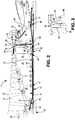
Fig. 2 is a sectional view of a thermal management system for a section of a gas turbine engine in accordance with the invention; and -
Fig. 3 is a sectional view showing an alternative arrangement for anti-vortex tubes used in the thermal management system ofFig. 2 . - Referring now to
Figure 2 , there is shown acompressor section 10 of a turbine engine, such as a high pressure compressor section, which includes the thermal management system of the present disclosure. Thecompressor section 10 includes ahollow shaft 12, known as a tie shaft, which connects thecompressor rotor 11 to a turbine rotor (not shown). In the case of thesection 10 being a high pressure compressor section, thetie shaft 12 connects thehigh pressure rotor 11 to the high pressure turbine rotor. In such a case, located within the interior of theshaft 12 is alow pressure shaft 14 which connects a low pressure compressor rotor (not shown) to a low pressure turbine rotor (not shown) of the engine. - The
compressor rotor 11 has a plurality of disks R1 - R8 connected to thetie shaft 12. Each respective disk may carry one ormore rotor blades 16. Each of the disks R1 - R8 has arim 18. A maingas flow path 20 is formed between therims 18 of the disks and acasing 22 which surrounds thecompressor rotor 11. A plurality of bore cavities are located between thedisk rims 18 and the outer diameter of thetie shaft 12. The bore cavities includeforward cavities aft cavities - A
front hub 42 is mounted to thetie shaft 12. One ormore flow holes 44 are provided in thefront hub 42. A supply of cooling air is delivered to therotor cavities flow holes 44. Prior to being delivered to theflow holes 44, the air may be cooled using aheat exchanger 46. The cooling air passing through theflow holes 44 conditions the disk temperature and transient response as well as controls the tie shaft temperature. After passing through the forward cavities, theflow 48 of cooling air exits through one or moreradial holes 50 in thetie shaft 12. - The
flow 48 of cooling air flowing through theholes 50, as shown inFig. 2 , mixes with anintershaft flow 52 of cooling air between thetie shaft 12 and thelow shaft 14. Theintershaft flow 52 may be created in any suitable manner. Theaft cavities main gas path 20 via one or moreradial bleed slots 56 located in adisk rim 18. Theflow 54 of bleed air may be brought down to the rotor inner diameter usinganti-vortex tubes 58 to minimize pressure loss while maximizing disk web conditioning. Theair cavities piston ring seal 60 between the aft side of theR6 disk bore 62 and the outer diameter wall of thetie shaft 12. The aft cavity flow of cooling air is typically hotter and at higher pressure than the forward cavity cooling air. As shown inFig. 2 , someleakage 59 of hotter aft cavity cooling air may occur under the R6 disk through the piston ring. Theleakage 59 may join or mix with the colder forwardcavity bore flow 48 prior to exiting the forward cavities through theholes 50 in thetie shaft 12. The majority of theflow 54 of cooling air moves aft under disk R8 and exits through an array ofaxial holes 66 in thefoot 68 of therear hub 69, mounted to thetie shaft 12, to form aflow 70 which flows on to a high pressure turbine (HPT)(not shown). The aft cavity flow 54 conditions the rotors R7 and R8 and also serves as turbine conditioning and blade cooling air. Radial gaps between the bores of rotors R1 to R8 and thetie shaft 12 may be held tight throughout all stages to enhance the heat transfer of the passing flow jet while operating sufficiently large to minimize pressure losses. - Intershaft
air flow 52 between thetie shaft 12 and thelow shaft 14 may be sourced from the same cooler supply as the forwardcavity air flow 48. Theintershaft air flow 52 cools thetie shaft 12 and mixes with the forwardcavity bore flow 48 coming through theholes 50 in thetie shaft 12. The mixed flow then travels aft to the low pressure turbine (LPT) section of the engine for cooling purposes. -
Rear hub flow 90 may be channeled closely along the rotor surface by a static flow guide. The gap may be held to a minimum allowable to avoid clashing. This allows the momentum of air flow to counter the effects of disk pumping and provide a more uniform flow thereby minimizing losses and potential sources of heat generation. - The outer diameter of the
tie shaft 12 may be designed to favor near-straight-line forward and aft bore flows and to keep the flow at a lowest possible radius. Thetie shaft 12 may feature thin wall barrels with wall thickness-to-radius ratios sized to prevent ovalization flutter under the air flows washing both the outer diameter and inner diameter at different velocities and axial/circumferential directions (same flow and counter flow)/clockwise and counterclockwise). Thecoupling nut 74 may be designed to have a low profile to preclude obstruction of the flow lines. - Segregation of the forward and aft bore flows 48, 54, and 59 with an interseal 60 along with
intershaft flow 52 allows optimization of the temperature and pressure of the flows to meet local high pressure compressor disk conditioning, overall tie shaft thermal expansion control, and turbine cooling requirements. This is achieved using existing rotor disk and shaft hardware to define flow/thermal zones avoiding additional disk components for the sole purpose of zone boundaries. The segregatedaft cavities radial bleed slots 56 andanti-vortex tubes 58 maximize the recoverable pressure from the source. Eachanti-vortex tube 58 may be positioned radially to allow free vortexing of the flow near the bore andupper web 80 of the R7 and R8 disks to provide high heat transfer rapid thermal response, thereby reducing stress inducing gradients. The higher temperatures of the aftcavities flow source forward cavities intershaft flow 52 with high heat transfer from counter-rotating walls, helps to maintain the lowest possible tie shaft temperature. This is significant in maintaining elevated preload levels in the rotor stack. Thecontoured flow guide 92 minimizes heat generation and rear hub temperature. - Referring now to
Fig. 3 , there is shown an alternative arrangement for theanti-vortex tubes 58. If desired, oneanti-vortex tube 58 may be attached to therear wall 82 of the R6 disk and a second anti-vortex tube 58' may be mounted to thefront wall 84 of the R8 rotor. If desired, the tube 58' may be shorter than thetube 58. - While the
compressor section 10 has been shown as having 8 disks, thesection 10 could have more or less disks. - There has been provided a thermal management system for a gas turbine engine. While the thermal management system has been discussed in the context of specific embodiments thereof, other unforeseeable alternatives, variations, and modifications may become apparent to those skilled in the art. Accordingly, it is intended to embrace those alternatives, modifications, and variations which fall within the broad scope of the appended claims.
Claims (1)
- A gas turbine engine comprising:a high pressure compressor section (10) having a high pressure compressor rotor (11);a low pressure compressor rotor;a high pressure turbine rotor;a low pressure turbine section comprising a low pressure turbine rotor;a hollow shaft (12), which connects the high pressure compressor rotor (11) to the high pressure turbine rotor;a low pressure shaft (14) located within the interior of the shaft (12), the low pressure shaft (14) connecting the low pressure compressor rotor to the low pressure turbine rotor;an intershaft space being defined between the low pressure shaft (14) and the hollow shaft (12);wherein the high pressure compressor rotor (11) comprises a plurality of disks (R1 - R8) connected to the hollow shaft (12), each of the disks (R1 - R8) having a rim (18)and a web;a plurality of bore cavities located between the disk rims (18) and the outer diameter of the hollow shaft (12), the bore cavities including at least one forward cavity (24, 26, 28, 30, 32, 34) and at least one aft cavity (36, 38, 40); anda thermal management system comprising:means for delivering a first stream (48) of cooling air to said at least one forward cavity (24, 26, 28, 30, 32, 34) for controlling disk temperature and shaft temperature in said at least one forward cavity (24, 26, 28, 30, 32, 34);means for delivering a second stream (54) of cooling air to said at least one aft cavity (36, 38, 40)for providing disk web cooling in said at least one aft cavity (36, 38, 40); andmeans for delivering a flow (52) of cooling air into said intershaft space; characterized by further comprising:means for allowing said first stream (48) of cooling air to exit said at least one forward cavity (24, 26, 28, 30, 32, 34) through said hollow shaft (12)into said intershaft space, whereby said first stream (48) of cooling air exiting said at least one forward cavity (24, 26, 28, 30, 32, 34) is mixed with said flow (52) of cooling air flowing through said intershaft space to form a mixed flow ; andmeans for conducting said mixed flow aft to said low pressure turbine section for cooling purposes.
Applications Claiming Priority (2)
| Application Number | Priority Date | Filing Date | Title |
|---|---|---|---|
| US13/454,304 US9234463B2 (en) | 2012-04-24 | 2012-04-24 | Thermal management system for a gas turbine engine |
| PCT/US2013/031955 WO2013162752A1 (en) | 2012-04-24 | 2013-03-15 | Thermal management system for a gas turbine engine |
Related Child Applications (1)
| Application Number | Title | Priority Date | Filing Date |
|---|---|---|---|
| EP17166881.7 Division-Into | 2017-04-18 |
Publications (3)
| Publication Number | Publication Date |
|---|---|
| EP2841753A1 EP2841753A1 (en) | 2015-03-04 |
| EP2841753A4 EP2841753A4 (en) | 2016-10-19 |
| EP2841753B1 true EP2841753B1 (en) | 2019-03-13 |
Family
ID=49380274
Family Applications (1)
| Application Number | Title | Priority Date | Filing Date |
|---|---|---|---|
| EP13781579.1A Active EP2841753B1 (en) | 2012-04-24 | 2013-03-15 | Gas turbine engine with thermal management system |
Country Status (3)
| Country | Link |
|---|---|
| US (1) | US9234463B2 (en) |
| EP (1) | EP2841753B1 (en) |
| WO (1) | WO2013162752A1 (en) |
Families Citing this family (25)
| Publication number | Priority date | Publication date | Assignee | Title |
|---|---|---|---|---|
| US10208609B2 (en) | 2014-06-09 | 2019-02-19 | General Electric Company | Turbine and methods of assembling the same |
| US10731502B2 (en) | 2014-11-03 | 2020-08-04 | Raytheon Technologies Corporation | High pressure compressor rotor thermal conditioning using outer diameter gas extraction |
| US10030582B2 (en) | 2015-02-09 | 2018-07-24 | United Technologies Corporation | Orientation feature for swirler tube |
| KR101675269B1 (en) | 2015-10-02 | 2016-11-11 | 두산중공업 주식회사 | Gas Turbine disk |
| US10612383B2 (en) * | 2016-01-27 | 2020-04-07 | General Electric Company | Compressor aft rotor rim cooling for high OPR (T3) engine |
| DE102016102049A1 (en) * | 2016-02-05 | 2017-08-10 | Rolls-Royce Deutschland Ltd & Co Kg | Gas turbine and method for conditioning the temperature of a turbine disk of a gas turbine |
| US10767485B2 (en) | 2018-01-08 | 2020-09-08 | Raytheon Technologies Corporation | Radial cooling system for gas turbine engine compressors |
| US10563672B2 (en) * | 2018-02-07 | 2020-02-18 | United Technologies Corporation | Gas turbine engine compressor |
| FR3078369B1 (en) * | 2018-02-23 | 2020-03-20 | Safran Aircraft Engines | TURBOMACHINE COMPRISING A HEAT EXCHANGER CONSISTING OF AT LEAST ONE INTER AUBES PLATFORM |
| US10746098B2 (en) | 2018-03-09 | 2020-08-18 | General Electric Company | Compressor rotor cooling apparatus |
| US10774742B2 (en) * | 2018-03-21 | 2020-09-15 | Raytheon Technologies Corporation | Flared anti-vortex tube rotor insert |
| US10808627B2 (en) * | 2018-03-26 | 2020-10-20 | Raytheon Technologies Corporation | Double bore basket |
| US10954796B2 (en) * | 2018-08-13 | 2021-03-23 | Raytheon Technologies Corporation | Rotor bore conditioning for a gas turbine engine |
| US11346282B2 (en) | 2019-01-18 | 2022-05-31 | Raytheon Technologies Corporation | Gas turbine engine component for acoustic attenuation |
| IT202000006439A1 (en) | 2020-03-26 | 2021-09-26 | Ge Avio Srl | METHOD AND APPARATUS FOR COOLING A PORTION OF A COUNTER-ROTARY TURBINE ENGINE |
| US20220213802A1 (en) | 2021-01-06 | 2022-07-07 | General Electric Company | System for controlling blade clearances within a gas turbine engine |
| US11365629B1 (en) | 2021-04-14 | 2022-06-21 | General Electric Company | Flow structure for turbine engine |
| US11674396B2 (en) | 2021-07-30 | 2023-06-13 | General Electric Company | Cooling air delivery assembly |
| US11920500B2 (en) | 2021-08-30 | 2024-03-05 | General Electric Company | Passive flow modulation device |
| US11692448B1 (en) | 2022-03-04 | 2023-07-04 | General Electric Company | Passive valve assembly for a nozzle of a gas turbine engine |
| CN117469030A (en) * | 2022-07-22 | 2024-01-30 | 通用电气公司 | Cooling systems for turbine engines |
| US12516606B2 (en) * | 2023-08-18 | 2026-01-06 | Rtx Corporation | Piston-ring seal leakage tolerant HPC tie-shaft |
| US12234733B1 (en) * | 2023-11-10 | 2025-02-25 | Rtx Corporation | Seal flow bypass |
| US20250257692A1 (en) * | 2024-02-09 | 2025-08-14 | Rtx Corporation | Thermal conditioning assembly for a gas turbine engine |
| US12291997B1 (en) | 2024-04-30 | 2025-05-06 | General Electric Company | Variable area turbine nozzle assembly |
Family Cites Families (22)
| Publication number | Priority date | Publication date | Assignee | Title |
|---|---|---|---|---|
| DE2633291C3 (en) * | 1976-07-23 | 1981-05-14 | Kraftwerk Union AG, 4330 Mülheim | Gas turbine system with cooling by two independent cooling air flows |
| US5472313A (en) | 1991-10-30 | 1995-12-05 | General Electric Company | Turbine disk cooling system |
| FR2690482B1 (en) * | 1992-04-23 | 1994-06-03 | Snecma | CIRCUIT FOR VENTILATION OF COMPRESSOR AND TURBINE DISCS. |
| US5271711A (en) | 1992-05-11 | 1993-12-21 | General Electric Company | Compressor bore cooling manifold |
| US5317877A (en) | 1992-08-03 | 1994-06-07 | General Electric Company | Intercooled turbine blade cooling air feed system |
| US5555721A (en) | 1994-09-28 | 1996-09-17 | General Electric Company | Gas turbine engine cooling supply circuit |
| US6134880A (en) | 1997-12-31 | 2000-10-24 | Concepts Eti, Inc. | Turbine engine with intercooler in bypass air passage |
| FR2782539B1 (en) * | 1998-08-20 | 2000-10-06 | Snecma | TURBOMACHINE HAVING A PRESSURIZED GAS SUPPLY DEVICE |
| US6267553B1 (en) | 1999-06-01 | 2001-07-31 | Joseph C. Burge | Gas turbine compressor spool with structural and thermal upgrades |
| FR2794816B1 (en) * | 1999-06-10 | 2001-07-06 | Snecma | HIGH PRESSURE COMPRESSOR STATOR |
| US6361277B1 (en) | 2000-01-24 | 2002-03-26 | General Electric Company | Methods and apparatus for directing airflow to a compressor bore |
| US20020108376A1 (en) | 2001-02-14 | 2002-08-15 | Stevens Eloy C. | Thermal management system for turbomachinery |
| DE10159670A1 (en) | 2001-12-05 | 2003-06-18 | Rolls Royce Deutschland | Vortex rectifier in the high pressure compressor of a gas turbine |
| US6910852B2 (en) | 2003-09-05 | 2005-06-28 | General Electric Company | Methods and apparatus for cooling gas turbine engine rotor assemblies |
| US7269955B2 (en) | 2004-08-25 | 2007-09-18 | General Electric Company | Methods and apparatus for maintaining rotor assembly tip clearances |
| US7448221B2 (en) * | 2004-12-17 | 2008-11-11 | United Technologies Corporation | Turbine engine rotor stack |
| FR2892148B1 (en) * | 2005-10-19 | 2011-07-22 | Snecma | TURBOREACTOR TREE SHAFT AND TURBOJET COMPRISING THE SAME |
| GB0603030D0 (en) | 2006-02-15 | 2006-03-29 | Rolls Royce Plc | Gas turbine engine rotor ventilation arrangement |
| US7870742B2 (en) * | 2006-11-10 | 2011-01-18 | General Electric Company | Interstage cooled turbine engine |
| FR2933458B1 (en) * | 2008-07-01 | 2010-09-03 | Snecma | AXIALO-CENTRIFUGAL COMPRESSOR WITH STEERING SYSTEM |
| US8650885B2 (en) | 2009-12-22 | 2014-02-18 | United Technologies Corporation | Retaining member for use with gas turbine engine shaft and method of assembly |
| US10018116B2 (en) | 2012-01-31 | 2018-07-10 | United Technologies Corporation | Gas turbine engine buffer system providing zoned ventilation |
-
2012
- 2012-04-24 US US13/454,304 patent/US9234463B2/en active Active
-
2013
- 2013-03-15 WO PCT/US2013/031955 patent/WO2013162752A1/en not_active Ceased
- 2013-03-15 EP EP13781579.1A patent/EP2841753B1/en active Active
Non-Patent Citations (1)
| Title |
|---|
| None * |
Also Published As
| Publication number | Publication date |
|---|---|
| US9234463B2 (en) | 2016-01-12 |
| WO2013162752A1 (en) | 2013-10-31 |
| EP2841753A4 (en) | 2016-10-19 |
| US20130280028A1 (en) | 2013-10-24 |
| EP2841753A1 (en) | 2015-03-04 |
Similar Documents
| Publication | Publication Date | Title |
|---|---|---|
| US9234463B2 (en) | Thermal management system for a gas turbine engine | |
| EP2540993B1 (en) | Aircraft gas turbine | |
| EP2702251B1 (en) | Turbine comprising a casing cooling duct | |
| US9816963B2 (en) | High pressure compressor thermal management | |
| EP1923539B1 (en) | Gas turbine with active tip clearance control | |
| EP2809909B1 (en) | Gas turbine engine buffer system providing zoned ventilation | |
| EP2218892B1 (en) | Cooled vane for gas turbine exhaust duct | |
| US8894352B2 (en) | Ring segment with forked cooling passages | |
| JP5036496B2 (en) | Leaching gap control turbine | |
| EP2820272B1 (en) | Buffer cooling system providing gas turbine engine architecture cooling | |
| EP2907978B1 (en) | Engine mid-turbine frame having distributive coolant flow | |
| US8092152B2 (en) | Device for cooling slots of a turbomachine rotor disk | |
| EP3018288B1 (en) | High pressure compressor rotor thermal conditioning using discharge pressure air and a corresponding method | |
| BR102016030609A2 (en) | GAS TURBINE MOTOR AND HEAT EXCHANGER SYSTEM | |
| US20140119880A1 (en) | Temperature control within a cavity of a turbine engine | |
| CN102187062A (en) | Ventilation of turbine high pressure turbine | |
| JP2008121677A (en) | Combined nozzle cooling engine | |
| JP2014111930A (en) | Gas turbine engine heat exchanger and assembly method of the same | |
| CN102454480A (en) | Axial compressor and associated operating method | |
| RU2506435C2 (en) | Gas turbine engine and method for radial clearance adjustment in gas turbine | |
| RU2352788C1 (en) | High-temperature gas turbine | |
| EP3312383B1 (en) | Air mixing systems having mixing chambers for gas turbine engines | |
| UA77163C2 (en) | Rotor of turbo-machine with combined air pump-through |
Legal Events
| Date | Code | Title | Description |
|---|---|---|---|
| PUAI | Public reference made under article 153(3) epc to a published international application that has entered the european phase |
Free format text: ORIGINAL CODE: 0009012 |
|
| 17P | Request for examination filed |
Effective date: 20141110 |
|
| AK | Designated contracting states |
Kind code of ref document: A1 Designated state(s): AL AT BE BG CH CY CZ DE DK EE ES FI FR GB GR HR HU IE IS IT LI LT LU LV MC MK MT NL NO PL PT RO RS SE SI SK SM TR |
|
| AX | Request for extension of the european patent |
Extension state: BA ME |
|
| DAX | Request for extension of the european patent (deleted) | ||
| RAP1 | Party data changed (applicant data changed or rights of an application transferred) |
Owner name: MTU AERO ENGINES AG Owner name: UNITED TECHNOLOGIES CORPORATION |
|
| RIN1 | Information on inventor provided before grant (corrected) |
Inventor name: CARMINATI, DANIEL Inventor name: JANG, DAVID S Inventor name: BENJAMIN, DANIEL Inventor name: PROESTLER, STEPHAN, DR. |
|
| RIC1 | Information provided on ipc code assigned before grant |
Ipc: F01D 5/08 20060101AFI20160523BHEP Ipc: F02C 7/18 20060101ALI20160523BHEP |
|
| RA4 | Supplementary search report drawn up and despatched (corrected) |
Effective date: 20160916 |
|
| RIC1 | Information provided on ipc code assigned before grant |
Ipc: F01D 5/08 20060101AFI20160912BHEP Ipc: F02C 7/18 20060101ALI20160912BHEP |
|
| RAP1 | Party data changed (applicant data changed or rights of an application transferred) |
Owner name: UNITED TECHNOLOGIES CORPORATION Owner name: MTU AERO ENGINES AG |
|
| STAA | Information on the status of an ep patent application or granted ep patent |
Free format text: STATUS: REQUEST FOR EXAMINATION WAS MADE |
|
| REG | Reference to a national code |
Ref country code: DE Ref legal event code: R079 Ref document number: 602013052336 Country of ref document: DE Free format text: PREVIOUS MAIN CLASS: F02K0003000000 Ipc: F01D0005080000 |
|
| RIC1 | Information provided on ipc code assigned before grant |
Ipc: F01D 5/08 20060101AFI20180702BHEP Ipc: F02C 7/18 20060101ALI20180702BHEP |
|
| GRAP | Despatch of communication of intention to grant a patent |
Free format text: ORIGINAL CODE: EPIDOSNIGR1 |
|
| STAA | Information on the status of an ep patent application or granted ep patent |
Free format text: STATUS: GRANT OF PATENT IS INTENDED |
|
| INTG | Intention to grant announced |
Effective date: 20180920 |
|
| RIN1 | Information on inventor provided before grant (corrected) |
Inventor name: JANG, DAVID S Inventor name: PROESTLER, STEPHAN, DR. Inventor name: CARMINATI, DANIEL Inventor name: BENJAMIN, DANIEL |
|
| GRAS | Grant fee paid |
Free format text: ORIGINAL CODE: EPIDOSNIGR3 |
|
| GRAA | (expected) grant |
Free format text: ORIGINAL CODE: 0009210 |
|
| STAA | Information on the status of an ep patent application or granted ep patent |
Free format text: STATUS: THE PATENT HAS BEEN GRANTED |
|
| AK | Designated contracting states |
Kind code of ref document: B1 Designated state(s): AL AT BE BG CH CY CZ DE DK EE ES FI FR GB GR HR HU IE IS IT LI LT LU LV MC MK MT NL NO PL PT RO RS SE SI SK SM TR |
|
| REG | Reference to a national code |
Ref country code: GB Ref legal event code: FG4D |
|
| REG | Reference to a national code |
Ref country code: CH Ref legal event code: EP Ref country code: AT Ref legal event code: REF Ref document number: 1107935 Country of ref document: AT Kind code of ref document: T Effective date: 20190315 |
|
| REG | Reference to a national code |
Ref country code: IE Ref legal event code: FG4D |
|
| REG | Reference to a national code |
Ref country code: DE Ref legal event code: R096 Ref document number: 602013052336 Country of ref document: DE |
|
| REG | Reference to a national code |
Ref country code: NL Ref legal event code: MP Effective date: 20190313 |
|
| REG | Reference to a national code |
Ref country code: LT Ref legal event code: MG4D |
|
| PG25 | Lapsed in a contracting state [announced via postgrant information from national office to epo] |
Ref country code: SE Free format text: LAPSE BECAUSE OF FAILURE TO SUBMIT A TRANSLATION OF THE DESCRIPTION OR TO PAY THE FEE WITHIN THE PRESCRIBED TIME-LIMIT Effective date: 20190313 Ref country code: FI Free format text: LAPSE BECAUSE OF FAILURE TO SUBMIT A TRANSLATION OF THE DESCRIPTION OR TO PAY THE FEE WITHIN THE PRESCRIBED TIME-LIMIT Effective date: 20190313 Ref country code: NO Free format text: LAPSE BECAUSE OF FAILURE TO SUBMIT A TRANSLATION OF THE DESCRIPTION OR TO PAY THE FEE WITHIN THE PRESCRIBED TIME-LIMIT Effective date: 20190613 Ref country code: LT Free format text: LAPSE BECAUSE OF FAILURE TO SUBMIT A TRANSLATION OF THE DESCRIPTION OR TO PAY THE FEE WITHIN THE PRESCRIBED TIME-LIMIT Effective date: 20190313 |
|
| PG25 | Lapsed in a contracting state [announced via postgrant information from national office to epo] |
Ref country code: HR Free format text: LAPSE BECAUSE OF FAILURE TO SUBMIT A TRANSLATION OF THE DESCRIPTION OR TO PAY THE FEE WITHIN THE PRESCRIBED TIME-LIMIT Effective date: 20190313 Ref country code: GR Free format text: LAPSE BECAUSE OF FAILURE TO SUBMIT A TRANSLATION OF THE DESCRIPTION OR TO PAY THE FEE WITHIN THE PRESCRIBED TIME-LIMIT Effective date: 20190614 Ref country code: NL Free format text: LAPSE BECAUSE OF FAILURE TO SUBMIT A TRANSLATION OF THE DESCRIPTION OR TO PAY THE FEE WITHIN THE PRESCRIBED TIME-LIMIT Effective date: 20190313 Ref country code: RS Free format text: LAPSE BECAUSE OF FAILURE TO SUBMIT A TRANSLATION OF THE DESCRIPTION OR TO PAY THE FEE WITHIN THE PRESCRIBED TIME-LIMIT Effective date: 20190313 Ref country code: LV Free format text: LAPSE BECAUSE OF FAILURE TO SUBMIT A TRANSLATION OF THE DESCRIPTION OR TO PAY THE FEE WITHIN THE PRESCRIBED TIME-LIMIT Effective date: 20190313 Ref country code: BG Free format text: LAPSE BECAUSE OF FAILURE TO SUBMIT A TRANSLATION OF THE DESCRIPTION OR TO PAY THE FEE WITHIN THE PRESCRIBED TIME-LIMIT Effective date: 20190613 |
|
| REG | Reference to a national code |
Ref country code: AT Ref legal event code: MK05 Ref document number: 1107935 Country of ref document: AT Kind code of ref document: T Effective date: 20190313 |
|
| PG25 | Lapsed in a contracting state [announced via postgrant information from national office to epo] |
Ref country code: RO Free format text: LAPSE BECAUSE OF FAILURE TO SUBMIT A TRANSLATION OF THE DESCRIPTION OR TO PAY THE FEE WITHIN THE PRESCRIBED TIME-LIMIT Effective date: 20190313 Ref country code: SK Free format text: LAPSE BECAUSE OF FAILURE TO SUBMIT A TRANSLATION OF THE DESCRIPTION OR TO PAY THE FEE WITHIN THE PRESCRIBED TIME-LIMIT Effective date: 20190313 Ref country code: CZ Free format text: LAPSE BECAUSE OF FAILURE TO SUBMIT A TRANSLATION OF THE DESCRIPTION OR TO PAY THE FEE WITHIN THE PRESCRIBED TIME-LIMIT Effective date: 20190313 Ref country code: IT Free format text: LAPSE BECAUSE OF FAILURE TO SUBMIT A TRANSLATION OF THE DESCRIPTION OR TO PAY THE FEE WITHIN THE PRESCRIBED TIME-LIMIT Effective date: 20190313 Ref country code: EE Free format text: LAPSE BECAUSE OF FAILURE TO SUBMIT A TRANSLATION OF THE DESCRIPTION OR TO PAY THE FEE WITHIN THE PRESCRIBED TIME-LIMIT Effective date: 20190313 Ref country code: PT Free format text: LAPSE BECAUSE OF FAILURE TO SUBMIT A TRANSLATION OF THE DESCRIPTION OR TO PAY THE FEE WITHIN THE PRESCRIBED TIME-LIMIT Effective date: 20190713 Ref country code: AL Free format text: LAPSE BECAUSE OF FAILURE TO SUBMIT A TRANSLATION OF THE DESCRIPTION OR TO PAY THE FEE WITHIN THE PRESCRIBED TIME-LIMIT Effective date: 20190313 Ref country code: ES Free format text: LAPSE BECAUSE OF FAILURE TO SUBMIT A TRANSLATION OF THE DESCRIPTION OR TO PAY THE FEE WITHIN THE PRESCRIBED TIME-LIMIT Effective date: 20190313 |
|
| REG | Reference to a national code |
Ref country code: CH Ref legal event code: PL |
|
| PG25 | Lapsed in a contracting state [announced via postgrant information from national office to epo] |
Ref country code: LU Free format text: LAPSE BECAUSE OF NON-PAYMENT OF DUE FEES Effective date: 20190315 Ref country code: SM Free format text: LAPSE BECAUSE OF FAILURE TO SUBMIT A TRANSLATION OF THE DESCRIPTION OR TO PAY THE FEE WITHIN THE PRESCRIBED TIME-LIMIT Effective date: 20190313 Ref country code: PL Free format text: LAPSE BECAUSE OF FAILURE TO SUBMIT A TRANSLATION OF THE DESCRIPTION OR TO PAY THE FEE WITHIN THE PRESCRIBED TIME-LIMIT Effective date: 20190313 |
|
| REG | Reference to a national code |
Ref country code: BE Ref legal event code: MM Effective date: 20190331 |
|
| REG | Reference to a national code |
Ref country code: DE Ref legal event code: R097 Ref document number: 602013052336 Country of ref document: DE |
|
| PG25 | Lapsed in a contracting state [announced via postgrant information from national office to epo] |
Ref country code: AT Free format text: LAPSE BECAUSE OF FAILURE TO SUBMIT A TRANSLATION OF THE DESCRIPTION OR TO PAY THE FEE WITHIN THE PRESCRIBED TIME-LIMIT Effective date: 20190313 Ref country code: IS Free format text: LAPSE BECAUSE OF FAILURE TO SUBMIT A TRANSLATION OF THE DESCRIPTION OR TO PAY THE FEE WITHIN THE PRESCRIBED TIME-LIMIT Effective date: 20190713 |
|
| PLBE | No opposition filed within time limit |
Free format text: ORIGINAL CODE: 0009261 |
|
| STAA | Information on the status of an ep patent application or granted ep patent |
Free format text: STATUS: NO OPPOSITION FILED WITHIN TIME LIMIT |
|
| PG25 | Lapsed in a contracting state [announced via postgrant information from national office to epo] |
Ref country code: IE Free format text: LAPSE BECAUSE OF NON-PAYMENT OF DUE FEES Effective date: 20190315 Ref country code: CH Free format text: LAPSE BECAUSE OF NON-PAYMENT OF DUE FEES Effective date: 20190331 Ref country code: LI Free format text: LAPSE BECAUSE OF NON-PAYMENT OF DUE FEES Effective date: 20190331 Ref country code: DK Free format text: LAPSE BECAUSE OF FAILURE TO SUBMIT A TRANSLATION OF THE DESCRIPTION OR TO PAY THE FEE WITHIN THE PRESCRIBED TIME-LIMIT Effective date: 20190313 Ref country code: MC Free format text: LAPSE BECAUSE OF FAILURE TO SUBMIT A TRANSLATION OF THE DESCRIPTION OR TO PAY THE FEE WITHIN THE PRESCRIBED TIME-LIMIT Effective date: 20190313 |
|
| 26N | No opposition filed |
Effective date: 20191216 |
|
| PG25 | Lapsed in a contracting state [announced via postgrant information from national office to epo] |
Ref country code: BE Free format text: LAPSE BECAUSE OF NON-PAYMENT OF DUE FEES Effective date: 20190331 Ref country code: SI Free format text: LAPSE BECAUSE OF FAILURE TO SUBMIT A TRANSLATION OF THE DESCRIPTION OR TO PAY THE FEE WITHIN THE PRESCRIBED TIME-LIMIT Effective date: 20190313 |
|
| PG25 | Lapsed in a contracting state [announced via postgrant information from national office to epo] |
Ref country code: TR Free format text: LAPSE BECAUSE OF FAILURE TO SUBMIT A TRANSLATION OF THE DESCRIPTION OR TO PAY THE FEE WITHIN THE PRESCRIBED TIME-LIMIT Effective date: 20190313 |
|
| PG25 | Lapsed in a contracting state [announced via postgrant information from national office to epo] |
Ref country code: MT Free format text: LAPSE BECAUSE OF NON-PAYMENT OF DUE FEES Effective date: 20190315 |
|
| PG25 | Lapsed in a contracting state [announced via postgrant information from national office to epo] |
Ref country code: CY Free format text: LAPSE BECAUSE OF FAILURE TO SUBMIT A TRANSLATION OF THE DESCRIPTION OR TO PAY THE FEE WITHIN THE PRESCRIBED TIME-LIMIT Effective date: 20190313 |
|
| PG25 | Lapsed in a contracting state [announced via postgrant information from national office to epo] |
Ref country code: HU Free format text: LAPSE BECAUSE OF FAILURE TO SUBMIT A TRANSLATION OF THE DESCRIPTION OR TO PAY THE FEE WITHIN THE PRESCRIBED TIME-LIMIT; INVALID AB INITIO Effective date: 20130315 |
|
| PG25 | Lapsed in a contracting state [announced via postgrant information from national office to epo] |
Ref country code: MK Free format text: LAPSE BECAUSE OF FAILURE TO SUBMIT A TRANSLATION OF THE DESCRIPTION OR TO PAY THE FEE WITHIN THE PRESCRIBED TIME-LIMIT Effective date: 20190313 |
|
| REG | Reference to a national code |
Ref country code: DE Ref legal event code: R081 Ref document number: 602013052336 Country of ref document: DE Owner name: RAYTHEON TECHNOLOGIES CORPORATION (N.D.GES.D.S, US Free format text: FORMER OWNERS: MTU AERO ENGINES AG, 80995 MUENCHEN, DE; UNITED TECHNOLOGIES CORPORATION, FARMINGTON, CONN., US Ref country code: DE Ref legal event code: R081 Ref document number: 602013052336 Country of ref document: DE Owner name: MTU AERO ENGINES AG, DE Free format text: FORMER OWNERS: MTU AERO ENGINES AG, 80995 MUENCHEN, DE; UNITED TECHNOLOGIES CORPORATION, FARMINGTON, CONN., US Ref country code: DE Ref legal event code: R081 Ref document number: 602013052336 Country of ref document: DE Owner name: RTX CORPORATION (N.D.GES.D. STAATES DELAWARE),, US Free format text: FORMER OWNERS: MTU AERO ENGINES AG, 80995 MUENCHEN, DE; UNITED TECHNOLOGIES CORPORATION, FARMINGTON, CONN., US |
|
| REG | Reference to a national code |
Ref country code: DE Ref legal event code: R081 Ref document number: 602013052336 Country of ref document: DE Owner name: MTU AERO ENGINES AG, DE Free format text: FORMER OWNERS: MTU AERO ENGINES AG, 80995 MUENCHEN, DE; RAYTHEON TECHNOLOGIES CORPORATION (N.D.GES.D.STAATES DELAWARE), ARLINGTON, VA, US Ref country code: DE Ref legal event code: R081 Ref document number: 602013052336 Country of ref document: DE Owner name: RTX CORPORATION (N.D.GES.D. STAATES DELAWARE),, US Free format text: FORMER OWNERS: MTU AERO ENGINES AG, 80995 MUENCHEN, DE; RAYTHEON TECHNOLOGIES CORPORATION (N.D.GES.D.STAATES DELAWARE), ARLINGTON, VA, US |
|
| PGFP | Annual fee paid to national office [announced via postgrant information from national office to epo] |
Ref country code: GB Payment date: 20260219 Year of fee payment: 14 |
|
| PGFP | Annual fee paid to national office [announced via postgrant information from national office to epo] |
Ref country code: DE Payment date: 20260219 Year of fee payment: 14 |
|
| PGFP | Annual fee paid to national office [announced via postgrant information from national office to epo] |
Ref country code: FR Payment date: 20260219 Year of fee payment: 14 |