EP2840806A1 - Ultrasonic generator manufacturing method and ultrasonic generator assembly system - Google Patents
Ultrasonic generator manufacturing method and ultrasonic generator assembly system Download PDFInfo
- Publication number
- EP2840806A1 EP2840806A1 EP13777739.7A EP13777739A EP2840806A1 EP 2840806 A1 EP2840806 A1 EP 2840806A1 EP 13777739 A EP13777739 A EP 13777739A EP 2840806 A1 EP2840806 A1 EP 2840806A1
- Authority
- EP
- European Patent Office
- Prior art keywords
- bolt
- shaped member
- axial direction
- attachment unit
- bar portion
- Prior art date
- Legal status (The legal status is an assumption and is not a legal conclusion. Google has not performed a legal analysis and makes no representation as to the accuracy of the status listed.)
- Granted
Links
Images




Classifications
-
- H—ELECTRICITY
- H10—SEMICONDUCTOR DEVICES; ELECTRIC SOLID-STATE DEVICES NOT OTHERWISE PROVIDED FOR
- H10N—ELECTRIC SOLID-STATE DEVICES NOT OTHERWISE PROVIDED FOR
- H10N30/00—Piezoelectric or electrostrictive devices
- H10N30/01—Manufacture or treatment
- H10N30/03—Assembling devices that include piezoelectric or electrostrictive parts
-
- B—PERFORMING OPERATIONS; TRANSPORTING
- B06—GENERATING OR TRANSMITTING MECHANICAL VIBRATIONS IN GENERAL
- B06B—METHODS OR APPARATUS FOR GENERATING OR TRANSMITTING MECHANICAL VIBRATIONS OF INFRASONIC, SONIC, OR ULTRASONIC FREQUENCY, e.g. FOR PERFORMING MECHANICAL WORK IN GENERAL
- B06B1/00—Methods or apparatus for generating mechanical vibrations of infrasonic, sonic, or ultrasonic frequency
- B06B1/02—Methods or apparatus for generating mechanical vibrations of infrasonic, sonic, or ultrasonic frequency making use of electrical energy
- B06B1/06—Methods or apparatus for generating mechanical vibrations of infrasonic, sonic, or ultrasonic frequency making use of electrical energy operating with piezoelectric effect or with electrostriction
-
- B—PERFORMING OPERATIONS; TRANSPORTING
- B06—GENERATING OR TRANSMITTING MECHANICAL VIBRATIONS IN GENERAL
- B06B—METHODS OR APPARATUS FOR GENERATING OR TRANSMITTING MECHANICAL VIBRATIONS OF INFRASONIC, SONIC, OR ULTRASONIC FREQUENCY, e.g. FOR PERFORMING MECHANICAL WORK IN GENERAL
- B06B1/00—Methods or apparatus for generating mechanical vibrations of infrasonic, sonic, or ultrasonic frequency
- B06B1/02—Methods or apparatus for generating mechanical vibrations of infrasonic, sonic, or ultrasonic frequency making use of electrical energy
- B06B1/06—Methods or apparatus for generating mechanical vibrations of infrasonic, sonic, or ultrasonic frequency making use of electrical energy operating with piezoelectric effect or with electrostriction
- B06B1/0607—Methods or apparatus for generating mechanical vibrations of infrasonic, sonic, or ultrasonic frequency making use of electrical energy operating with piezoelectric effect or with electrostriction using multiple elements
- B06B1/0611—Methods or apparatus for generating mechanical vibrations of infrasonic, sonic, or ultrasonic frequency making use of electrical energy operating with piezoelectric effect or with electrostriction using multiple elements in a pile
-
- B—PERFORMING OPERATIONS; TRANSPORTING
- B60—VEHICLES IN GENERAL
- B60B—VEHICLE WHEELS; CASTORS; AXLES FOR WHEELS OR CASTORS; INCREASING WHEEL ADHESION
- B60B1/00—Spoked wheels; Spokes thereof
- B60B1/06—Wheels with compression spokes
-
- H—ELECTRICITY
- H10—SEMICONDUCTOR DEVICES; ELECTRIC SOLID-STATE DEVICES NOT OTHERWISE PROVIDED FOR
- H10N—ELECTRIC SOLID-STATE DEVICES NOT OTHERWISE PROVIDED FOR
- H10N30/00—Piezoelectric or electrostrictive devices
- H10N30/01—Manufacture or treatment
- H10N30/05—Manufacture of multilayered piezoelectric or electrostrictive devices, or parts thereof, e.g. by stacking piezoelectric bodies and electrodes
- H10N30/057—Manufacture of multilayered piezoelectric or electrostrictive devices, or parts thereof, e.g. by stacking piezoelectric bodies and electrodes by stacking bulk piezoelectric or electrostrictive bodies and electrodes
-
- Y—GENERAL TAGGING OF NEW TECHNOLOGICAL DEVELOPMENTS; GENERAL TAGGING OF CROSS-SECTIONAL TECHNOLOGIES SPANNING OVER SEVERAL SECTIONS OF THE IPC; TECHNICAL SUBJECTS COVERED BY FORMER USPC CROSS-REFERENCE ART COLLECTIONS [XRACs] AND DIGESTS
- Y10—TECHNICAL SUBJECTS COVERED BY FORMER USPC
- Y10T—TECHNICAL SUBJECTS COVERED BY FORMER US CLASSIFICATION
- Y10T29/00—Metal working
- Y10T29/42—Piezoelectric device making
Definitions
- the present invention relates to a manufacturing method of an ultrasonic generating device which configured to generate an ultrasonic vibration when supplied with a current, and an assembling system of the ultrasonic generating device.
- Patent Literature 1 has disclosed an ultrasonic generating device which is configured to generate an ultrasonic vibration when supplied with a current.
- This ultrasonic generating device includes a bolt which includes a head portion, and a bar portion smaller in an outside diameter than the head portion.
- An attachment unit which includes piezoelectric elements configured to convert the current to the ultrasonic vibration is attached to the bar portion of the bolt.
- the attachment unit is fastened between the head portion of the bolt and a nut which is a fastening member, and is contracted.
- the piezoelectric element is contracted by the contraction of the attachment unit, and the conversion from the current to the ultrasonic vibration is properly performed by the piezoelectric elements.
- the attachment unit which includes the piezoelectric elements.
- the attachment unit is fastened by the nut to apply a compressive force to the attachment unit (piezoelectric elements) from the nut and contract the attachment unit.
- a compressive force is applied to the attachment unit (piezoelectric elements) by a force applying unit separate from the nut to contract the attachment unit.
- the attachment unit is contracted to a predetermined contraction state
- the nut is attached to the bar portion of the bolt, and the attachment unit is fastened between the head portion of the bolt and the nut.
- the predetermined contraction state of the attachment unit is maintained.
- both ends of the bolt are fixed in directions parallel to a longitudinal axis, and are fixed ends.
- Patent Literature 1 Jpn. Pat. Appln. KOKAI Publication No. 64-36200
- the contraction state of the attachment unit including the piezoelectric elements varies according to the variation in fastening torque of the nut, the characteristic variation of the bolt, and the characteristic variation of the nut.
- vibration characteristics of the ultrasonic vibrations to be generated vary from device to device.
- the attachment unit is contracted to the predetermined contraction state by the force applying unit, and the attachment unit is fastened by the nut to maintain the predetermined contraction state.
- both ends of the bolt are fixed in the directions parallel to the longitudinal axis, and are fixed ends.
- the bolt is not stretched by the elastic force of the contracted attachment unit.
- both ends of the bolt are not fixed in the directions parallel to the longitudinal axis, and are free ends.
- the bolt is expanded by the elastic force of the attachment unit contracted to the predetermined contraction state.
- the vibration characteristic of the ultrasonic vibration to be generated varies because of the expansion of the bolt.
- An object of the present invention is to provide a manufacturing method of an ultrasonic generating device and an assembling system of the ultrasonic generating device that effectively inhibit the variation of the vibration characteristic of the ultrasonic generating device.
- a manufacturing method of an ultrasonic generating device including: attaching an attachment unit to a bar portion from a second axial direction side in a bolt-shaped member, the attachment unit including a piezoelectric element configured to convert a current to an ultrasonic vibration, a head portion forming a first end of the bolt-shaped member on a first axial direction side, the first axial direction being a direction parallel to a longitudinal axis, the bar portion smaller in an outside diameter than the head portion forming a second end of the bolt-shaped member on the second axial direction side, the second axial direction being opposite to the first axial direction; fixing, as a fixed end, the second end of the bolt-shaped member to which the attachment unit is attached, by using a bolt fixing portion of a jig, while the bolt-shaped member is expandable by a movement of the first end which is a free end toward the first axial direction; applying a compressive force to the attachment unit toward the first axial
- an assembling system of an ultrasonic generating device including: a bolt-shaped member, the bolt-shaped member including a head portion forming a first end of the bolt-shaped member on a first axial direction side, the first axial direction being a direction parallel to a longitudinal axis, and a bar portion which is smaller in an outside diameter than the head portion and which forms a second end of the bolt-shaped member on the second axial direction side, the second axial direction being opposite to the first axial direction; an attachment unit which includes a piezoelectric element configured to convert a current to an ultrasonic vibration, and which is attached to the bar portion of the bolt-shaped member from the second axial direction side; a jig which includes a bolt-shaped member fixing portion, the bolt-shaped member fixing portion fixing, as a fixed end, the second end of the bolt-shaped member to which the attachment unit is attached while the bolt-shaped member is expandable by an movement of the first end which is a free end toward the first axial
- a manufacturing method of an ultrasonic generating device and an assembling system of the ultrasonic generating device which effectively inhibit the variation of the vibration characteristic of the ultrasonic generating device, can be provided.
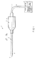
- FIG. 1 is a diagram showing an ultrasonic treatment device 1 according to the present embodiment.
- the ultrasonic treatment device 1 is an example in which an ultrasonic generating device 10 described later is used.
- the ultrasonic treatment device 1 has a longitudinal axis C.
- one of two directions parallel to the longitudinal axis C is a distal direction (direction of an arrow C1 in FIG. 1 ), and a direction opposite to the distal direction is a proximal direction (direction of an arrow C2 in FIG. 1 ).
- the ultrasonic treatment device 1 includes a vibration generating unit 2, and an ultrasonic probe 3 which extends from a proximal end to a distal end thereof along the longitudinal axis C.
- the vibration generating unit 2 includes a vibrator case 11. One end of a cable 5 is connected to a proximal end of the oscillator case 11. The other end of the cable 5 is connected to a power supply unit 6.
- the power supply unit 6 includes an ultrasonic generating current supplier 7 and an input section 9. A distal treatment section 8 is provided to a distal portion of the ultrasonic probe 3.
- FIG. 2 is a diagram showing a configuration of the vibration generating unit 2.
- the ultrasonic generating device 10 is provided inside the vibrator case 11.
- One end of each of electric wiring lines 13A and 13B is connected to the ultrasonic generating device 10.
- the other end of each of the electric wiring lines 13A and 13B is connected to the ultrasonic generating current supplier 7 of the power supply unit 6 through an inside of the cable 5.
- An ultrasonic vibration is generated in the ultrasonic generating device 10 by the supply of a current to the ultrasonic generating device 10 from the ultrasonic generating current supplier 7 via the electric wiring lines 13A and 13B.
- a horn 15 configured to increase the amplitude of the ultrasonic vibration is coupled to a distal direction side of the ultrasonic generating device 10.
- the horn 15 is attached to the transducer case 11.
- An internal thread portion 17 is formed in a distal portion of the horn 15.
- An external thread portion 19 is formed in a proximal portion of the ultrasonic probe 3.
- the external thread portion 19 is threaded into the internal thread portion 17 of the horn 15, and the ultrasonic probe 3 is thereby attached to the vibration generating unit 2.
- the ultrasonic vibration generated in the ultrasonic generating device 10 is transmitted to the ultrasonic probe 3.
- the distal treatment section 8 of the ultrasonic probe 3 treats a treatment target such as a living tissue by using the ultrasonic vibration.
- the ultrasonic vibration is a longitudinal vibration having vibration directions and a transmission direction parallel to the longitudinal axis C.
- FIG. 3 and FIG. 4 are diagrams showing a configuration of the ultrasonic generating device 10.
- the ultrasonic generating device 10 includes a bolt-shaped member 21 as a holing member which is configured to hold an attachment unit 30 described later.
- the bolt-shaped member 21 includes a bar portion 23 as a shaft to which the attachment unit 30 is inserted and which extends parallel to the longitudinal axis C, and a head portion 22 as a regulating portion which is provided to one end portion of the bar portion 23 and which is configured to regulate the movement of the attachment unit 30 inserted to the bar portion 23.
- An outside diameter of the bar portion 23 is smaller than an outside diameter of the head portion 22.
- Longitudinal axis directions of the bolt-shaped member 21 correspond to the longitudinal axis C.
- one of directions parallel to the longitudinal axis C is a first axial direction (direction of an arrow A1 in FIG. 3 and FIG. 4 ), and a direction opposite to the first axial direction is a second axial direction (direction of an arrow A2 in FIG. 3 and FIG. 4 ).
- a first end E1 on the first axial direction side is formed by the head portion 22, and a second end E2 on the second axial direction side is formed by the bar portion 23.
- an external thread portion 25 is formed on an outer peripheral portion at an end portion on the second axial direction side.
- a depression 26 depressed toward the first axial direction is provided at the second end E2 of the bolt-shaped member 21.
- An internal thread portion 28 is formed in the concave portion 26.
- the attachment unit 30 is attached to the bar portion 23 of the bolt-shaped member 21.
- the attachment unit 30 includes (three in the present embodiment) ring-shaped piezoelectric elements 29A to 29C.
- the piezoelectric elements 29A to 29C are made of, for example, ceramics.
- the attachment unit 30 also includes a first electrode 31 and a second electrode 32.
- the first electrode 31 includes an electrode ring portion 33A located to the first axial direction side of the piezoelectric element 29A, and an electrode ring portion 33B located between the piezoelectric element 29B and the piezoelectric element 29C.
- the first electrode 31 also includes an electrode belt-shaped portion 35A continuing between the electrode ring portion 33A and the electrode ring portion 33B, and an electrode belt-shaped portion 35B which has one end continuing to the electrode ring portion 33B.
- One end of the electric wiring line 13A is connected to the electrode belt-shaped portion 35B of the first electrode 31.
- the second electrode 32 includes an electrode ring portion 37A located between the piezoelectric element 29A and the piezoelectric element 29B, and an electrode ring portion 37B located to the second axial direction side of the piezoelectric element 29C.
- the second electrode 32 also includes an electrode belt-shaped portion 39A continuing between the electrode ring portion 37A and the electrode ring portion 37B, and an electrode belt-shaped portion 39B which has one end continuing to the electrode ring portion 37B.
- One end of the electric wiring line 13B is connected to the electrode belt-shaped portion 39B of the second electrode 32.
- a current (alternating current) is supplied to the first electrode 31 and the second electrode 32 from the ultrasonic generating current supplier 7 of the power supply unit 6.
- the piezoelectric elements 29A to 29C convert the current to an ultrasonic vibration, and the ultrasonic vibration is generated.
- the attachment unit 30 includes insulating rings 41A and 41B.
- the insulating ring 41A is located to the first axial direction side of the electrode ring portion 33A of the first electrode 31.
- the insulating ring 41B is located to the second axial direction side of the ring portion 37B of the second electrode 32.
- a nut 43 which is a fastening member is attached to the bar portion 23 of the bolt-shaped member 21 in addition to the attachment unit 30.
- the nut 43 is located to the second axial direction side of the attachment unit 30 (washer 42).
- An internal thread portion 45 is provided to the nut 43.
- the attachment unit 30 (the piezoelectric elements 29A to 29C, the first electrode 31, the second electrode 32, the insulating rings 41A and 41B, and the washer 42) is fastened between the nut 43 and the head portion 22 of the bolt-shaped member 21. Therefore, the attachment unit 30 is fixed between the nut 43 and the head portion 22 of the bolt-shaped member 21.
- An outside diameter D1 of the washer 42 is larger than an outside diameter D2 of the nut 43.
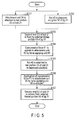
- FIG. 5 is a flowchart showing the manufacturing method of the ultrasonic generating device 10.
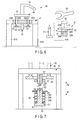
- FIG. 6 is a diagram showing an assembling system 50 of the ultrasonic generating device 10 for use in the manufacture of the ultrasonic generating device 10. As shown in FIG. 6 , the assembling system 50 includes the above-mentioned bolt-shaped member 21, the attachment unit 30, and the nut 43 constituting the ultrasonic generating device 10.
- the assembling system 50 also includes a jig 51.
- the jig 51 includes a seat 55, and legs 57A and 57B.
- the jig 51 is placed on the ground by the legs 57A and 57B.
- the jig 51 is provided with a jig bar portion 52 protruding toward a vertically downward direction from the seat 55.
- An external thread portion 53 is formed at a vertically-downward-direction-side end portion of the jig bar portion 52.
- Hole portions 59A and 59B which pass penetrate through the seat 55 in vertically upward-and-downward directions are provided in the seat 55.
- the assembling system 50 includes a force applying unit 60.
- the force applying unit 60 includes an operation lever 61 located to the vertically upward direction side of the seat 55 of the jig 51.
- the operation lever 61 is connected to a plate-shaped portion 62.
- Link portions 65A and 65B extend toward the vertically downward direction from the plate-shaped portion 62.
- the link portion 65A extends toward the vertically downward direction side beyond the seat 55 through the hole portion 59A.
- the link portion 65B extends toward the vertically downward direction side beyond the seat 55 through the hole portion 59B.
- the link portions 65A and 65B are connected to a plate-shaped press portion 63 located to the vertically downward direction side of the seat 55.
- a hole portion 67 which penetrates through the press portion 63 in the vertically upward-and-downward directions is provided to the press portion 63.
- the jig bar portion 52 is inserted through the hole portion 67 of the press portion 63.
- the force applying unit 60 can be moved relative to the jig 51 in the vertically upward-and-downward directions by the manual operation of the operation lever 61.
- the force applying unit 60 is supported by a support unit (not shown) with being movable in the vertically upward-and-downward directions.
- the assembling system 50 also includes a spanner 69 as an attaching member used to attach the nut 43 to the bar portion 23 of the bolt-shaped member 21.
- a spanner 69 is used to rotate the nut 43 relative to the bar portion 23.
- the attachment unit 30 (the piezoelectric elements 29A to 29C, the first electrode 31, the second electrode 32, the insulating rings 41A and 41B, and the washer 42) is first attached to the bar portion 23 of the bolt-shaped member 21 (step S101).
- FIG. 7 is a diagram showing a state before the second end E2 of the bolt-shaped member 21 is fixed by the external thread portion 53 of the jig 51 in the manufacture of the ultrasonic generating device 10.
- the bar portion 23 of the bolt-shaped member 21 is inserted through the attachment unit 30 including the piezoelectric elements 29A to 29C, and the attachment unit 30 is thereby attached to the bar portion 23. That is, the attachment unit 30 is attached to the bar portion 23 of the bolt-shaped member 21 from the second axial direction side.
- components constituting the attachment unit 30 such as the piezoelectric elements 29A to 29C, the first electrode 31, and the second electrode 32 are located at the above-mentioned positions.
- the first axial direction (direction of the arrow A1 in FIG. 7 ) corresponds to the vertically downward direction
- the second axial direction corresponds to the vertically upward direction.
- the nut 43 which is the fastening member is disposed on the jig bar portion 52 of the jig 51 (step S102) in simultaneous with the attachment of the attachment unit 30 to the bar portion 23 (step S101).
- the nut 43 is disposed on the jig bar portion 52. That is, the nut 43 is disposed on the jig bar portion 52 from the first axial direction side.
- the external thread portion 53 is located at the end portion of the jig bar portion 52 on the first axial direction side.
- FIG. 8 is a diagram showing a state in which the second end E2 of the bolt-shaped member 21 is fixed by the external thread portion 53 of the jig 51 in the manufacture of the ultrasonic generating device 10.
- the external thread portion 53 of the jig 51 is a bolt-shaped member fixing portion (fixing portion) which fixes, as a fixed end, the second end E2 of the bolt-shaped member 21 to which the attachment unit 30 is attached.
- the first end E1 of the bolt-shaped member 21 is a free end movable parallel to the longitudinal axis C.
- the first end E1 as the free end moves toward the first axial direction.
- the bolt-shaped member 21 stretches.
- the nut 43 When the second end E2 of the bolt-shaped member 21 is fixed, the nut 43 is located in the jig bar portion 52 of the jig 51. That is, before the second end E2 of the bolt-shaped member 21 is fixed, the nut 43 is disposed on the jig bar portion 52 (step S102).
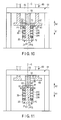
- FIG. 9 is a diagram showing a state in which the compressive force F1 is applied to the attachment unit 30 in the manufacture of the ultrasonic generating device 10.
- an inside diameter D3 of the hole portion 67 formed in the press portion 63 of the force applying unit 60 is larger than the outside diameter D2 of the nut 43.
- the inside diameter D3 of the hole portion 67 is smaller than the outside diameter D1 of the washer 42 of the attachment unit 30.
- the press portion 63 abuts on the washer 42 by the movement of the force applying unit 60 in the first axial direction.
- the compressive force F1 is applied to the attachment unit 30 from the force applying unit 60 toward the first axial direction.
- the attachment unit 30 including the piezoelectric elements 29A to 29C is contracted by the compressive force F1.
- a first elastic force F2 is generated in the attachment unit 30 by the contraction of the attachment unit 30.
- the first elastic force F2 acts on the head portion 22 of the bolt-shaped member 21 from the attachment unit 30.
- the first end E1 is the free end
- the second end E2 is the fixed end.
- the first elastic force F2 acts on the bolt-shaped member 21
- the first end E1 moves toward the first axial direction, and the bolt-shaped member 21 expands.
- a second elastic force F3 is generated in the bolt-shaped member 21 by the expansion of the bolt-shaped member 21.
- the second elastic force F3 acts toward a direction opposite to that of the first elastic force F2.
- the second elastic force F3 increases in accordance with the increase in the expansion amount of the bolt-shaped member 21.
- the bolt-shaped member 21 expands until the second elastic force F3 equals the first elastic force F2. That is, the bolt-shaped member 21 expands up to a balanced condition in which the first elastic force F2 and the second elastic force F3 are in balance. In the balanced condition, the bolt-shaped member 21 does not expand even if the compressive force F1 is applied to the attachment unit 30 by the force applying unit 60.
- FIG. 10 is a diagram showing a state in which the nut 43 is attached to the bar portion 23 of the bolt-shaped member 21 in the manufacture of the ultrasonic generating device 10. As shown in FIG. 10 , the nut 43 is attached while the compressive force F1 is being applied to the attachment unit 30 from the force applying unit 60. As a result, the balanced condition in which the first elastic force F2 and the second elastic force F3 are in balance is maintained when the nut 43 is attached.
- the spanner 69 is used to rotate the nut 43 relative to the bar portion 23.
- the nut 43 located in the jig bar portion 52 moves up to the bar portion 23 toward the first axial direction.
- the nut 43 is attached to the bar portion 23 of the bolt-shaped member 21.
- the attachment unit 30 is fastened between the nut 43 and the head portion 22 of the bolt-shaped member 21 by the attachment of the nut 43. As a result, the balanced condition in which the first elastic force F2 and the second elastic force F3 are in balance is maintained.
- the nut 43 is attached so as to the bar portion 23 of the bolt-shaped member 21 to maintain the balanced condition of the first elastic force F2 and the second elastic force F3.
- the nut 43 is attached with a small fastening torque, and the fastening of the nut 43 prevents the attachment unit 30 from being further contracted from the balanced condition.
- the nut 43 may be manually rotated without the use of the spanner 69.
- FIG. 11 is a diagram showing a state in which the application of the compressive force F1 to the attachment unit 30 by the force applying unit 60 is stopped in the manufacture of the ultrasonic generating device 10.
- the force applying unit 60 is moved toward the second axial direction (vertically upward direction).
- the press portion 63 of the force applying unit 60 is out of contact with the washer 42, and the application of the compressive force F1 to the attachment unit 30 from the force applying unit 60 is stopped.
- the attachment unit 30 including the piezoelectric elements 29A to 29C is fastened between the nut 43 and the head portion 22 of the bolt-shaped member 21 by the nut 43, and fixed between the nut 43 and the head portion 22.
- the compressive force F1 is not applied to the attachment unit 30 from the force applying unit 60, the balanced condition in which the first elastic force F2 and the second elastic force F3 are in balance is maintained.
- the internal thread portion 28 of the bolt-shaped member 21 is then unthreaded from the external thread portion 53 of the jig 51.
- the second end E2 of the bolt-shaped member 21 is unfixed from the external thread portion 53 of the jig 51 (step S107). In this way, the ultrasonic generating device 10 is manufactured.
- the manufacturing method of the ultrasonic generating device 10 and the assembling system 50 described above is provided by the manufacturing method of the ultrasonic generating device 10 and the assembling system 50 described above. That is, during the manufacture of the ultrasonic generating device 10, the compressive force F1 is applied to the attachment unit 30 including the piezoelectric elements 29A to 29C by the force applying unit 60 separate from the nut 43. Since the attachment unit 30 is not contracted by the fastening of the nut 43, the fastening torque of the nut 43, the characteristics of the bolt-shaped member 21, and the characteristics of the nut 43 have no influence on the contracted state of the attachment unit 30 (the piezoelectric elements 29A to 29C). Therefore, it is possible to effectively prevent the contracted state of the attachment units 30 from varying due to differences in the ultrasonic generating devices 10. This makes it possible to effectively prevent the vibration characteristics of the ultrasonic vibrations from varying due to differences in the ultrasonic generating devices 10, and prevent the vibration characteristics from varying under the influence of differences in the characteristics of the bolts.
- the compressive force F1 is applied to the attachment unit 30 from the force applying unit 60 toward the first axial direction while the first end E1 of the bolt-shaped member 21 is a free end and the second end E2 of the bolt-shaped member 21 is the fixed end.
- the attachment unit 30 is contracted by the compressive force F1, so that the first elastic force F2 is generated in the attachment unit 30.
- the bolt-shaped member 21 is expanded by the first elastic force F2, and the second elastic force F3 which acts toward a direction opposite to the first elastic force F2 is generated in the bolt-shaped member 21.
- the bolt-shaped member 21 expands to the balanced condition in which the first elastic force F2 and the second elastic force F3 are in balance.
- the nut 43 In the balanced condition, the nut 43 is attached to the bar portion 23 of the bolt-shaped member 21, and the attachment unit 30 is fastened between the nut 43 and the head portion 22 of the bolt-shaped member 21.
- the balanced condition in which the first elastic force F2 and the second elastic force F3 are in balance is maintained. Since the ultrasonic generating device 10 is manufactured as described above, the first elastic force F2 and the second elastic force F3 are in balance at the completion of the ultrasonic generating device 10. Therefore, the expansion of the bolt-shaped member 21 caused by the first elastic force F2 is effectively prevented after the manufacture of the ultrasonic generating device 10.
- the second end E2 of the bolt-shaped member 21 is fixed as the fixed end while the first axial direction corresponds to the vertically downward direction and the second axial direction corresponds to the vertically upward direction.
- the operation lever 61 of the force applying unit 60 is manually operated to apply the compressive force F1 to the attachment unit 30 from the force applying unit 60.
- the present invention is not limited to this.
- the second end E2 of the bolt-shaped member 21 may be fixed as the fixed end while the first axial direction (direction of the arrow A1 in FIG. 12 ) and the second axial direction (direction of the arrow A2 in FIG. 12 ) are perpendicular to the vertical directions.
- a jig 71 is used instead of the jig 51.
- the first axial direction is a first horizontal direction perpendicular to the vertical directions
- the second axial direction is a second horizontal direction opposite to the first horizontal direction.
- the jig 71 includes a seat 75, and a jig bar portion 72 protruding from the seat 75 toward the first axial direction (first horizontal direction).
- the nut 43 which is the fastening member is disposed on the jig bar portion 72 before the second end E2 of the bolt-shaped member 21 is fixed.
- An external thread portion 73 is formed at an end portion of the jig bar portion 72 on the first axial direction side.
- the external thread portion 73 is a fixing portion (bolt-shaped member fixing portion) which fixes the second end E2 of the bolt-shaped member 21 to which the attachment unit 30 is attached. When the second end E2 is fixed, the first end E1 of the bolt-shaped member 21 is a free end.
- the bolt-shaped member 21 can be expanded by the movement of the first end E1 toward the first axial direction.
- Hole portions 79A and 79B which pass through the seat 75 along the longitudinal axis C are provided to the seat 75.
- a force applying unit 80 is used instead of the force applying unit 60.
- the force applying unit 80 includes a body portion 82 located to the second axial direction (second horizontal direction) side of the seat 75 of the jig 71. Expanding-and-contracting portions 85A and 85B extend from the body portion 82 toward the first axial direction.
- the telescopic portion 85A extends toward the first axial direction side beyond the seat 75 through the hole portion 79A.
- the telescopic portion 85B extends toward the first axial direction side beyond the seat 75 through the hole portion 79B.
- the telescopic portions 85A and 85B are connected to a plate-shaped press portion 83 located to the first axial direction side of the seat 75.
- a hole portion 87 which penetrates through the press portion 83 along the longitudinal axis C is provided in the press portion 83.
- the jig bar portion 72 is inserted through the hole portion 87 of the press portion 83.
- One end of a tube 93 is connected to the body portion 82 of the force applying unit 80.
- the other end of the tube 93 is connected to a hydraulic tank 91.
- the hydraulic tank 91 is electrically connected to an input section 92.
- the press portion 83 since the hole portion 87 is provided to the press portion 83, the press portion 83 does not contact the nut 43 located in the jig bar portion 72 when the press portion 83 moves toward the first axial direction. Thus, the press portion 83 is movable toward the first axial direction side beyond the nut 43.
- the compressive force (F1) has only to be applied to the attachment unit 30 from the force applying unit (60, 80) toward the first axial direction while the first end E1 of the bolt-shaped member 21 is the free end and the second end E2 is the fixed end.
- the attachment unit 30 is contracted, and the bolt-shaped member 21 is expanded by the first elastic force (F2) of the contracted attachment unit 30.
- the bolt-shaped member 21 expands up to the balanced condition in which the second elastic force (F3) of the expanded bolt-shaped member 21 and the first elastic force (F2) are in balance.
- the second end E2 of the bolt-shaped member 21 is fixed as the fixed end when the internal thread portion 28 of the bolt-shaped member 21 is threaded to the external thread portion 53 of the jig 51.
- the present invention is not limited to this.
- an engagement concave 95 depressed from the second end E2 of the bolt-shaped member 21 toward the first axial direction may be provided.
- the section of the engagement slot 95 is substantially hexagonally shaped.
- an engagement protrusion 96 is formed at the first-axial-direction-side end portion of the jig bar portion 52 of the jig 51.
- the section of the engagement protrusion 96 is substantially hexagonally shaped which is correspond to the engagement slot 95, and the engagement protrusion 96 can engage with the engagement slot 95.
- the engagement protrusion 96 is engaged with the engagement slot 95, the second end E2 of the bolt-shaped member 21 is fixed as the fixed end. That is, the engagement protrusion 96 is a fixing portion which fixes, as a fixed end, the second end E2 of the bolt-shaped member 21 to which the attachment unit 30 is attached.
- the jig (51, 71) has only to be provided with the fixing portion (53, 73, 96) which fixes, as the fixed end, the second end E2 of the bolt-shaped member 21 to which the attachment unit 30 is attached.
- the attachment unit 30 is fastened between the nut 43 and the head portion 22 of the bolt-shaped member 21 by the nut 43.
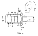
- a U-shaped member 97 may be used as the fastening member.
- the U-shaped member 97 is attached to the bar portion 23 of the bolt-shaped member 21 from one of directions perpendicular to the longitudinal axis C.
- a width D4 of a slot of the U-shaped member 97 is smaller than an outside diameter D5 of the bar portion 23. This ensures that the U-shaped member 97 is fixed to the bar portion 23 when the U-shaped member 97 is attached to the bar portion 23.
- the U-shaped member 97 which is the fastening member is attached to the bar portion 23 in the balanced condition in which the first elastic force F2 of the attachment unit 30 and the second elastic force F3 of the bolt-shaped member 21 are in balance, as in the first embodiment.
- the attachment unit 30 including the piezoelectric elements 29A to 29C is fastened between the U-shaped member 97 and the head portion 22 of the bolt-shaped member 21. Consequently, the balanced condition in which the first elastic force F2 and the second elastic force F3 are in balance is maintained.
- the U-shaped member 97 is attached to the bar portion from one of the directions perpendicular to the longitudinal axis C, it is not necessary to provide the jig bar portion (52, 72) in the jig (51, 71). That is, in contrast with the first embodiment, it is not necessary to dispose the fastening member (43) on the jig bar portion (52, 72) before the second end E2 of the bolt-shaped member 21 is fixed as the fixed end.
- the ultrasonic generating device 10 is more easily manufactured.
- the fastening member (43, 97) has only to be attached to the bar portion 23 of the bolt-shaped member 21 in the balanced condition in which the second elastic force F3 of the expanded bolt-shaped member 21 and the first elastic force F2 of the attachment unit 30 are in balance. Consequently, the attachment unit 30 is fastened between the fastening member (43, 97) and the head portion 22 of the bolt-shaped member 21, and the balanced condition is maintained.
- the attachment unit 30 includes the piezoelectric elements 29A to 29C, the first electrode 31, the second electrode 32, the insulating rings 41A and 41B, and the washer 42.
- the present invention is not limited to this.
- no insulating rings 41A and 41B may be provided, and four piezoelectric elements (29A to 29C) may be provided. That is, the attachment unit 30 has only to include at least one piezoelectric element (29A to 29C).
Landscapes
- Engineering & Computer Science (AREA)
- Manufacturing & Machinery (AREA)
- Mechanical Engineering (AREA)
- General Electrical Machinery Utilizing Piezoelectricity, Electrostriction Or Magnetostriction (AREA)
- Surgical Instruments (AREA)
- Transducers For Ultrasonic Waves (AREA)
Abstract
Description
- The present invention relates to a manufacturing method of an ultrasonic generating device which configured to generate an ultrasonic vibration when supplied with a current, and an assembling system of the ultrasonic generating device.
- Patent Literature 1 has disclosed an ultrasonic generating device which is configured to generate an ultrasonic vibration when supplied with a current. This ultrasonic generating device includes a bolt which includes a head portion, and a bar portion smaller in an outside diameter than the head portion. An attachment unit which includes piezoelectric elements configured to convert the current to the ultrasonic vibration is attached to the bar portion of the bolt. The attachment unit is fastened between the head portion of the bolt and a nut which is a fastening member, and is contracted. The piezoelectric element is contracted by the contraction of the attachment unit, and the conversion from the current to the ultrasonic vibration is properly performed by the piezoelectric elements.
- In the manufacture of the ultrasonic generating device having the configuration described above, it is necessary to contract the attachment unit which includes the piezoelectric elements. In a general manufacturing method, the attachment unit is fastened by the nut to apply a compressive force to the attachment unit (piezoelectric elements) from the nut and contract the attachment unit. In the manufacturing method according to Patent Literature 1, a compressive force is applied to the attachment unit (piezoelectric elements) by a force applying unit separate from the nut to contract the attachment unit. When the attachment unit is contracted to a predetermined contraction state, the nut is attached to the bar portion of the bolt, and the attachment unit is fastened between the head portion of the bolt and the nut. As a result, the predetermined contraction state of the attachment unit is maintained. Here, when the compressive force is applied to the attachment unit from the force applying unit, both ends of the bolt are fixed in directions parallel to a longitudinal axis, and are fixed ends.
- Patent Literature 1: Jpn. Pat. Appln. KOKAI Publication No.
64-36200 - In the manufacture of the ultrasonic generating device, when the attachment unit (piezoelectric elements) is contracted by the fastening of the nut, the contraction state of the attachment unit including the piezoelectric elements varies according to the variation in fastening torque of the nut, the characteristic variation of the bolt, and the characteristic variation of the nut. Thus, even if each of ultrasonic generating devices having the same designs is manufactured, vibration characteristics of the ultrasonic vibrations to be generated vary from device to device.
- In the ultrasonic generating device according to Patent Literature 1, the attachment unit is contracted to the predetermined contraction state by the force applying unit, and the attachment unit is fastened by the nut to maintain the predetermined contraction state. However, in the manufacture of the ultrasonic generating device, when the compressive force is applied to the attachment unit from the force applying unit, both ends of the bolt are fixed in the directions parallel to the longitudinal axis, and are fixed ends. Thus, when the compressive force is applied to the attachment unit from the force applying unit, the bolt is not stretched by the elastic force of the contracted attachment unit. On the other hand, in the manufactured ultrasonic generating device, both ends of the bolt are not fixed in the directions parallel to the longitudinal axis, and are free ends. Thus, the bolt is expanded by the elastic force of the attachment unit contracted to the predetermined contraction state. The vibration characteristic of the ultrasonic vibration to be generated varies because of the expansion of the bolt.
- The present invention has been made in view of the above-mentioned problems. An object of the present invention is to provide a manufacturing method of an ultrasonic generating device and an assembling system of the ultrasonic generating device that effectively inhibit the variation of the vibration characteristic of the ultrasonic generating device.
- To solve above mentioned problems, according to one aspect of the invention, a manufacturing method of an ultrasonic generating device, the method including: attaching an attachment unit to a bar portion from a second axial direction side in a bolt-shaped member, the attachment unit including a piezoelectric element configured to convert a current to an ultrasonic vibration, a head portion forming a first end of the bolt-shaped member on a first axial direction side, the first axial direction being a direction parallel to a longitudinal axis, the bar portion smaller in an outside diameter than the head portion forming a second end of the bolt-shaped member on the second axial direction side, the second axial direction being opposite to the first axial direction; fixing, as a fixed end, the second end of the bolt-shaped member to which the attachment unit is attached, by using a bolt fixing portion of a jig, while the bolt-shaped member is expandable by a movement of the first end which is a free end toward the first axial direction; applying a compressive force to the attachment unit toward the first axial direction by a force applying unit while the second end of the bolt-shaped member is fixed and thereby contracting the attachment unit, and expanding the bolt-shaped member by a first elastic force of the contracted attachment unit; and attaching a fastening member to the bar portion of the bolt-shaped member in a balanced condition in which a second elastic force of the expanded bolt-shaped member and the first elastic force of the attachment unit are in balance, and fastening the attachment unit between the fastening member and the head portion of the bolt-shaped member to maintain the balanced condition.
- According to one another aspect of the invention, an assembling system of an ultrasonic generating device, the system including: a bolt-shaped member, the bolt-shaped member including a head portion forming a first end of the bolt-shaped member on a first axial direction side, the first axial direction being a direction parallel to a longitudinal axis, and a bar portion which is smaller in an outside diameter than the head portion and which forms a second end of the bolt-shaped member on the second axial direction side, the second axial direction being opposite to the first axial direction; an attachment unit which includes a piezoelectric element configured to convert a current to an ultrasonic vibration, and which is attached to the bar portion of the bolt-shaped member from the second axial direction side; a jig which includes a bolt-shaped member fixing portion, the bolt-shaped member fixing portion fixing, as a fixed end, the second end of the bolt-shaped member to which the attachment unit is attached while the bolt-shaped member is expandable by an movement of the first end which is a free end toward the first axial direction; a force applying unit which is configured to apply a compressive force to the attachment unit toward the first axial direction while the second end of the bolt-shaped member is fixed, and thereby configured to contract the attachment unit, the force applying unit being configured to expand the bolt-shaped member by a first elastic force of the contracted attachment unit; and a fastening member which is attached to the bar portion of the bolt-shaped member in a balanced condition in which a second elastic force of the expanded bolt-shaped member and the first elastic force of the attachment unit are in balance, and which is configured to fasten the attachment unit between the fastening member and the head portion of the bolt-shaped member to maintain the balanced condition.
- According to the present invention, a manufacturing method of an ultrasonic generating device and an assembling system of the ultrasonic generating device, which effectively inhibit the variation of the vibration characteristic of the ultrasonic generating device, can be provided.
-
-
FIG. 1 is a schematic diagram showing an ultrasonic treatment device according to a first embodiment of the present invention; -
FIG. 2 is a schematic sectional view showing a configuration of a vibration generating unit according to the first embodiment; -
FIG. 3 is a schematic perspective view showing the configuration of an ultrasonic generating device according to the first embodiment; -
FIG. 4 is a schematic sectional view showing the configuration of the ultrasonic generating device according to the first embodiment; -
FIG. 5 is a flowchart showing a manufacturing method of the ultrasonic generating device according to the first embodiment; -
FIG. 6 is a schematic diagram showing an assembling system of the ultrasonic generating device for use in the manufacture of the ultrasonic generating device according to the first embodiment; -
FIG. 7 is a schematic diagram showing a state before a second end of a bolt-shaped member is fixed by an external thread portion of a jig in the manufacture of the ultrasonic generating device according to the first embodiment; -
FIG. 8 is a schematic diagram showing a state in which the second end of the bolt-shaped member is fixed by the external thread portion of the jig in the manufacture of the ultrasonic generating device according to the first embodiment; -
FIG. 9 is a schematic diagram showing a state in which the compressive force is applied to an attachment unit after the state inFIG. 8 in the manufacture of the ultrasonic generating device according to the first embodiment; -
FIG. 10 is a schematic diagram showing a state in which a nut is attached to a bar portion of the bolt-shaped member in the manufacture of the ultrasonic generating device according to the first embodiment; -
FIG. 11 is a schematic diagram showing a state in which the application of the compressive force to the attachment unit by a force applying unit is stopped after the state inFIG. 10 in the manufacture of the ultrasonic generating device according to the first embodiment; -
FIG. 12 is a schematic diagram showing the assembling system of the ultrasonic generating device according to a first modification; -
FIG. 13 is a schematic perspective view showing the bolt-shaped member and a jig bar portion of the jig according to a second modification; and -
FIG. 14 is a schematic perspective view showing the configuration of the ultrasonic generating device according to a third modification. - A first embodiment of the present invention is described with reference to
FIG. 1 to FIG. 6 .FIG. 1 is a diagram showing an ultrasonic treatment device 1 according to the present embodiment. Here, the ultrasonic treatment device 1 is an example in which anultrasonic generating device 10 described later is used. As shown inFIG. 1 , the ultrasonic treatment device 1 has a longitudinal axis C. Here, one of two directions parallel to the longitudinal axis C is a distal direction (direction of an arrow C1 inFIG. 1 ), and a direction opposite to the distal direction is a proximal direction (direction of an arrow C2 inFIG. 1 ). The ultrasonic treatment device 1 includes a vibration generatingunit 2, and anultrasonic probe 3 which extends from a proximal end to a distal end thereof along the longitudinal axis C. - The vibration generating
unit 2 includes avibrator case 11. One end of acable 5 is connected to a proximal end of theoscillator case 11. The other end of thecable 5 is connected to apower supply unit 6. Thepower supply unit 6 includes an ultrasonic generating current supplier 7 and aninput section 9. A distal treatment section 8 is provided to a distal portion of theultrasonic probe 3. -
FIG. 2 is a diagram showing a configuration of the vibration generatingunit 2. As shown inFIG. 2 , theultrasonic generating device 10 is provided inside thevibrator case 11. One end of each ofelectric wiring lines ultrasonic generating device 10. The other end of each of theelectric wiring lines power supply unit 6 through an inside of thecable 5. An ultrasonic vibration is generated in theultrasonic generating device 10 by the supply of a current to theultrasonic generating device 10 from the ultrasonic generating current supplier 7 via theelectric wiring lines horn 15 configured to increase the amplitude of the ultrasonic vibration is coupled to a distal direction side of theultrasonic generating device 10. Thehorn 15 is attached to thetransducer case 11. Aninternal thread portion 17 is formed in a distal portion of thehorn 15. - An
external thread portion 19 is formed in a proximal portion of theultrasonic probe 3. Theexternal thread portion 19 is threaded into theinternal thread portion 17 of thehorn 15, and theultrasonic probe 3 is thereby attached to thevibration generating unit 2. When theultrasonic probe 3 is attached to thevibration generating unit 2, the ultrasonic vibration generated in theultrasonic generating device 10 is transmitted to theultrasonic probe 3. When the ultrasonic vibration is transmitted to the distal treatment section 8 of theultrasonic probe 3, the distal treatment section 8 treats a treatment target such as a living tissue by using the ultrasonic vibration. The ultrasonic vibration is a longitudinal vibration having vibration directions and a transmission direction parallel to the longitudinal axis C. -
FIG. 3 andFIG. 4 are diagrams showing a configuration of theultrasonic generating device 10. As shown inFIG. 3 andFIG. 4 , theultrasonic generating device 10 includes a bolt-shapedmember 21 as a holing member which is configured to hold anattachment unit 30 described later. The bolt-shapedmember 21 includes abar portion 23 as a shaft to which theattachment unit 30 is inserted and which extends parallel to the longitudinal axis C, and ahead portion 22 as a regulating portion which is provided to one end portion of thebar portion 23 and which is configured to regulate the movement of theattachment unit 30 inserted to thebar portion 23. An outside diameter of thebar portion 23 is smaller than an outside diameter of thehead portion 22. Longitudinal axis directions of the bolt-shapedmember 21 correspond to the longitudinal axis C. - Here, in the
ultrasonic generating device 10, one of directions parallel to the longitudinal axis C is a first axial direction (direction of an arrow A1 inFIG. 3 andFIG. 4 ), and a direction opposite to the first axial direction is a second axial direction (direction of an arrow A2 inFIG. 3 andFIG. 4 ). - In the bolt-shaped
member 21, a first end E1 on the first axial direction side is formed by thehead portion 22, and a second end E2 on the second axial direction side is formed by thebar portion 23. - In the
bar portion 23, anexternal thread portion 25 is formed on an outer peripheral portion at an end portion on the second axial direction side. Adepression 26 depressed toward the first axial direction is provided at the second end E2 of the bolt-shapedmember 21. Aninternal thread portion 28 is formed in theconcave portion 26. - The
attachment unit 30 is attached to thebar portion 23 of the bolt-shapedmember 21. Theattachment unit 30 includes (three in the present embodiment) ring-shapedpiezoelectric elements 29A to 29C. Thepiezoelectric elements 29A to 29C are made of, for example, ceramics. Theattachment unit 30 also includes afirst electrode 31 and asecond electrode 32. - The
first electrode 31 includes anelectrode ring portion 33A located to the first axial direction side of thepiezoelectric element 29A, and anelectrode ring portion 33B located between thepiezoelectric element 29B and thepiezoelectric element 29C. Thefirst electrode 31 also includes an electrode belt-shapedportion 35A continuing between theelectrode ring portion 33A and theelectrode ring portion 33B, and an electrode belt-shapedportion 35B which has one end continuing to theelectrode ring portion 33B. One end of theelectric wiring line 13A is connected to the electrode belt-shapedportion 35B of thefirst electrode 31. - The
second electrode 32 includes anelectrode ring portion 37A located between thepiezoelectric element 29A and thepiezoelectric element 29B, and anelectrode ring portion 37B located to the second axial direction side of thepiezoelectric element 29C. Thesecond electrode 32 also includes an electrode belt-shapedportion 39A continuing between theelectrode ring portion 37A and theelectrode ring portion 37B, and an electrode belt-shapedportion 39B which has one end continuing to theelectrode ring portion 37B. One end of theelectric wiring line 13B is connected to the electrode belt-shapedportion 39B of thesecond electrode 32. - According to this configuration, a current (alternating current) is supplied to the
first electrode 31 and thesecond electrode 32 from the ultrasonic generating current supplier 7 of thepower supply unit 6. When the current is supplied to thefirst electrode 31 and thesecond electrode 32, thepiezoelectric elements 29A to 29C convert the current to an ultrasonic vibration, and the ultrasonic vibration is generated. - The
attachment unit 30 includes insulatingrings ring 41A is located to the first axial direction side of theelectrode ring portion 33A of thefirst electrode 31. The insulatingring 41B is located to the second axial direction side of thering portion 37B of thesecond electrode 32. By the provision of the insulatingring 41A, the current supplied from the ultrasonic generating current supplier 7 is not transmitted toward the first axial direction side from the insulatingring 41A. By the provision of the insulatingring 41B, the current supplied from the ultrasonic generating current supplier 7 is not transmitted toward the second axial direction side from the insulatingring 41B. Theattachment unit 30 also includes awasher 42 provided to the second axial direction side of the insulatingring 41B. - A
nut 43 which is a fastening member is attached to thebar portion 23 of the bolt-shapedmember 21 in addition to theattachment unit 30. Thenut 43 is located to the second axial direction side of the attachment unit 30 (washer 42). Aninternal thread portion 45 is provided to thenut 43. When theinternal thread portion 45 is threaded to theexternal thread portion 25 of thebar portion 23, thenut 43 is attached to thebar portion 23. By the provision of thenut 43, the attachment unit 30 (thepiezoelectric elements 29A to 29C, thefirst electrode 31, thesecond electrode 32, the insulatingrings nut 43 and thehead portion 22 of the bolt-shapedmember 21. Therefore, theattachment unit 30 is fixed between thenut 43 and thehead portion 22 of the bolt-shapedmember 21. An outside diameter D1 of thewasher 42 is larger than an outside diameter D2 of thenut 43. - Now, a manufacturing method of the
ultrasonic generating device 10 is described.FIG. 5 is a flowchart showing the manufacturing method of theultrasonic generating device 10.FIG. 6 is a diagram showing an assemblingsystem 50 of theultrasonic generating device 10 for use in the manufacture of theultrasonic generating device 10. As shown inFIG. 6 , the assemblingsystem 50 includes the above-mentioned bolt-shapedmember 21, theattachment unit 30, and thenut 43 constituting theultrasonic generating device 10. - The assembling
system 50 also includes ajig 51. Thejig 51 includes aseat 55, andlegs jig 51 is placed on the ground by thelegs jig 51 is provided with ajig bar portion 52 protruding toward a vertically downward direction from theseat 55. Anexternal thread portion 53 is formed at a vertically-downward-direction-side end portion of thejig bar portion 52.Hole portions seat 55 in vertically upward-and-downward directions are provided in theseat 55. - The assembling
system 50 includes aforce applying unit 60. Theforce applying unit 60 includes anoperation lever 61 located to the vertically upward direction side of theseat 55 of thejig 51. Theoperation lever 61 is connected to a plate-shapedportion 62.Link portions portion 62. Thelink portion 65A extends toward the vertically downward direction side beyond theseat 55 through thehole portion 59A. Similarly, thelink portion 65B extends toward the vertically downward direction side beyond theseat 55 through thehole portion 59B. - The
link portions press portion 63 located to the vertically downward direction side of theseat 55. Ahole portion 67 which penetrates through thepress portion 63 in the vertically upward-and-downward directions is provided to thepress portion 63. Thejig bar portion 52 is inserted through thehole portion 67 of thepress portion 63. According to this configuration described above, theforce applying unit 60 can be moved relative to thejig 51 in the vertically upward-and-downward directions by the manual operation of theoperation lever 61. Theforce applying unit 60 is supported by a support unit (not shown) with being movable in the vertically upward-and-downward directions. - The assembling
system 50 also includes aspanner 69 as an attaching member used to attach thenut 43 to thebar portion 23 of the bolt-shapedmember 21. When thenut 43 is attached to thebar portion 23, thespanner 69 is used to rotate thenut 43 relative to thebar portion 23. As shown inFIG. 5 , when theultrasonic generating device 10 is manufactured, the attachment unit 30 (thepiezoelectric elements 29A to 29C, thefirst electrode 31, thesecond electrode 32, the insulatingrings bar portion 23 of the bolt-shaped member 21 (step S101).FIG. 7 is a diagram showing a state before the second end E2 of the bolt-shapedmember 21 is fixed by theexternal thread portion 53 of thejig 51 in the manufacture of theultrasonic generating device 10. As shown inFIG. 7 , thebar portion 23 of the bolt-shapedmember 21 is inserted through theattachment unit 30 including thepiezoelectric elements 29A to 29C, and theattachment unit 30 is thereby attached to thebar portion 23. That is, theattachment unit 30 is attached to thebar portion 23 of the bolt-shapedmember 21 from the second axial direction side. - Here, components constituting the
attachment unit 30 such as thepiezoelectric elements 29A to 29C, thefirst electrode 31, and thesecond electrode 32 are located at the above-mentioned positions. In the present embodiment, the first axial direction (direction of the arrow A1 inFIG. 7 ) corresponds to the vertically downward direction, and the second axial direction (direction of the arrow A2 inFIG. 7 ) corresponds to the vertically upward direction. - The
nut 43 which is the fastening member is disposed on thejig bar portion 52 of the jig 51 (step S102) in simultaneous with the attachment of theattachment unit 30 to the bar portion 23 (step S101). As shown inFIG. 7 , when thejig bar portion 52 is inserted through thenut 43, thenut 43 is disposed on thejig bar portion 52. That is, thenut 43 is disposed on thejig bar portion 52 from the first axial direction side. Theexternal thread portion 53 is located at the end portion of thejig bar portion 52 on the first axial direction side. - The second end E2 of the bolt-shaped
member 21 is fixed as a fixed end by theexternal thread portion 53 of the jig 51 (step S103).FIG. 8 is a diagram showing a state in which the second end E2 of the bolt-shapedmember 21 is fixed by theexternal thread portion 53 of thejig 51 in the manufacture of theultrasonic generating device 10. As shown inFIG. 8 , when theinternal thread portion 28 of the bolt-shapedmember 21 is threaded to theexternal thread portion 53 of thejig 51, the second end E2 of the bolt-shapedmember 21 is fixed. That is, theexternal thread portion 53 of thejig 51 is a bolt-shaped member fixing portion (fixing portion) which fixes, as a fixed end, the second end E2 of the bolt-shapedmember 21 to which theattachment unit 30 is attached. - Here, when the second end E2 of the bolt-shaped
member 21 is fixed, the first end E1 of the bolt-shapedmember 21 is a free end movable parallel to the longitudinal axis C. Thus, when, for example, an external force is applied to the bolt-shapedmember 21 toward the first axial direction, the first end E1 as the free end moves toward the first axial direction. When the first end E1 moves toward the first axial direction while the second end E2 is fixed, the bolt-shapedmember 21 stretches. - When the second end E2 of the bolt-shaped
member 21 is fixed, thenut 43 is located in thejig bar portion 52 of thejig 51. That is, before the second end E2 of the bolt-shapedmember 21 is fixed, thenut 43 is disposed on the jig bar portion 52 (step S102). - The
force applying unit 60 is then moved toward the first axial direction (vertically downward direction), and a compressive force F1 is applied to theattachment unit 30 by the force applying unit 60 (step S104).FIG. 9 is a diagram showing a state in which the compressive force F1 is applied to theattachment unit 30 in the manufacture of theultrasonic generating device 10. As shown inFIG. 9 , an inside diameter D3 of thehole portion 67 formed in thepress portion 63 of theforce applying unit 60 is larger than the outside diameter D2 of thenut 43. Thus, when theforce applying unit 60 moves toward the first axial direction (direction of the arrow A1 inFIG. 9 ), thepress portion 63 does not contact thenut 43 located to thejig bar portion 52, and thepress portion 63 moves toward the first axial direction side beyond thenut 43. - The inside diameter D3 of the
hole portion 67 is smaller than the outside diameter D1 of thewasher 42 of theattachment unit 30. Thus, thepress portion 63 abuts on thewasher 42 by the movement of theforce applying unit 60 in the first axial direction. When thepress portion 63 abuts on thewasher 42, the compressive force F1 is applied to theattachment unit 30 from theforce applying unit 60 toward the first axial direction. Theattachment unit 30 including thepiezoelectric elements 29A to 29C is contracted by the compressive force F1. A first elastic force F2 is generated in theattachment unit 30 by the contraction of theattachment unit 30. - The first elastic force F2 acts on the
head portion 22 of the bolt-shapedmember 21 from theattachment unit 30. Here, in the bolt-shapedmember 21, the first end E1 is the free end, and the second end E2 is the fixed end. Thus, when the first elastic force F2 acts on the bolt-shapedmember 21, the first end E1 moves toward the first axial direction, and the bolt-shapedmember 21 expands. - A second elastic force F3 is generated in the bolt-shaped
member 21 by the expansion of the bolt-shapedmember 21. The second elastic force F3 acts toward a direction opposite to that of the first elastic force F2. The second elastic force F3 increases in accordance with the increase in the expansion amount of the bolt-shapedmember 21. The bolt-shapedmember 21 expands until the second elastic force F3 equals the first elastic force F2. That is, the bolt-shapedmember 21 expands up to a balanced condition in which the first elastic force F2 and the second elastic force F3 are in balance. In the balanced condition, the bolt-shapedmember 21 does not expand even if the compressive force F1 is applied to theattachment unit 30 by theforce applying unit 60. - In the balanced condition, the
nut 43 is attached to thebar portion 23 of the bolt-shaped member 21 (step S105).FIG. 10 is a diagram showing a state in which thenut 43 is attached to thebar portion 23 of the bolt-shapedmember 21 in the manufacture of theultrasonic generating device 10. As shown inFIG. 10 , thenut 43 is attached while the compressive force F1 is being applied to theattachment unit 30 from theforce applying unit 60. As a result, the balanced condition in which the first elastic force F2 and the second elastic force F3 are in balance is maintained when thenut 43 is attached. - When the
nut 43 is attached to thebar portion 23, thespanner 69 is used to rotate thenut 43 relative to thebar portion 23. As a result, thenut 43 located in thejig bar portion 52 moves up to thebar portion 23 toward the first axial direction. When theinternal thread portion 45 of thenut 43 is threaded to theexternal thread portion 25 of the bolt-shapedmember 21, thenut 43 is attached to thebar portion 23 of the bolt-shapedmember 21. Theattachment unit 30 is fastened between thenut 43 and thehead portion 22 of the bolt-shapedmember 21 by the attachment of thenut 43. As a result, the balanced condition in which the first elastic force F2 and the second elastic force F3 are in balance is maintained. In other words, thenut 43 is attached so as to thebar portion 23 of the bolt-shapedmember 21 to maintain the balanced condition of the first elastic force F2 and the second elastic force F3. Thenut 43 is attached with a small fastening torque, and the fastening of thenut 43 prevents theattachment unit 30 from being further contracted from the balanced condition. Thenut 43 may be manually rotated without the use of thespanner 69. - The application of the compressive force F1 to the
attachment unit 30 by theforce applying unit 60 is then stopped (step S106).FIG. 11 is a diagram showing a state in which the application of the compressive force F1 to theattachment unit 30 by theforce applying unit 60 is stopped in the manufacture of theultrasonic generating device 10. As shown inFIG. 11 , after thenut 43 is attached to thebar portion 23 of the bolt-shapedmember 21, theforce applying unit 60 is moved toward the second axial direction (vertically upward direction). As a result, thepress portion 63 of theforce applying unit 60 is out of contact with thewasher 42, and the application of the compressive force F1 to theattachment unit 30 from theforce applying unit 60 is stopped. - Here, the
attachment unit 30 including thepiezoelectric elements 29A to 29C is fastened between thenut 43 and thehead portion 22 of the bolt-shapedmember 21 by thenut 43, and fixed between thenut 43 and thehead portion 22. Thus, even if the compressive force F1 is not applied to theattachment unit 30 from theforce applying unit 60, the balanced condition in which the first elastic force F2 and the second elastic force F3 are in balance is maintained. - The
internal thread portion 28 of the bolt-shapedmember 21 is then unthreaded from theexternal thread portion 53 of thejig 51. As a result, the second end E2 of the bolt-shapedmember 21 is unfixed from theexternal thread portion 53 of the jig 51 (step S107). In this way, theultrasonic generating device 10 is manufactured. - Accordingly, the following advantageous effects are provided by the manufacturing method of the
ultrasonic generating device 10 and the assemblingsystem 50 described above. That is, during the manufacture of theultrasonic generating device 10, the compressive force F1 is applied to theattachment unit 30 including thepiezoelectric elements 29A to 29C by theforce applying unit 60 separate from thenut 43. Since theattachment unit 30 is not contracted by the fastening of thenut 43, the fastening torque of thenut 43, the characteristics of the bolt-shapedmember 21, and the characteristics of thenut 43 have no influence on the contracted state of the attachment unit 30 (thepiezoelectric elements 29A to 29C). Therefore, it is possible to effectively prevent the contracted state of theattachment units 30 from varying due to differences in theultrasonic generating devices 10. This makes it possible to effectively prevent the vibration characteristics of the ultrasonic vibrations from varying due to differences in theultrasonic generating devices 10, and prevent the vibration characteristics from varying under the influence of differences in the characteristics of the bolts. - During the manufacture of the
ultrasonic generating device 10, the compressive force F1 is applied to theattachment unit 30 from theforce applying unit 60 toward the first axial direction while the first end E1 of the bolt-shapedmember 21 is a free end and the second end E2 of the bolt-shapedmember 21 is the fixed end. Thus, theattachment unit 30 is contracted by the compressive force F1, so that the first elastic force F2 is generated in theattachment unit 30. The bolt-shapedmember 21 is expanded by the first elastic force F2, and the second elastic force F3 which acts toward a direction opposite to the first elastic force F2 is generated in the bolt-shapedmember 21. The bolt-shapedmember 21 expands to the balanced condition in which the first elastic force F2 and the second elastic force F3 are in balance. In the balanced condition, thenut 43 is attached to thebar portion 23 of the bolt-shapedmember 21, and theattachment unit 30 is fastened between thenut 43 and thehead portion 22 of the bolt-shapedmember 21. Thus, even if the application of the compressive force F1 to theattachment unit 30 is canceled, the balanced condition in which the first elastic force F2 and the second elastic force F3 are in balance is maintained. Since theultrasonic generating device 10 is manufactured as described above, the first elastic force F2 and the second elastic force F3 are in balance at the completion of theultrasonic generating device 10. Therefore, the expansion of the bolt-shapedmember 21 caused by the first elastic force F2 is effectively prevented after the manufacture of theultrasonic generating device 10. Consequently, it is possible to effectively prevent the vibration characteristic of the ultrasonic vibration of the manufacturedultrasonic generating device 10 from changing from the time of the completion of theultrasonic generating device 10, and also effectively prevent the vibration characteristic from varying under the influence of the characteristic of the bolt. - In the first embodiment, the second end E2 of the bolt-shaped
member 21 is fixed as the fixed end while the first axial direction corresponds to the vertically downward direction and the second axial direction corresponds to the vertically upward direction. However, the present invention is not limited to this. Moreover, in the first embodiment, theoperation lever 61 of theforce applying unit 60 is manually operated to apply the compressive force F1 to theattachment unit 30 from theforce applying unit 60. However, the present invention is not limited to this. - For example, as in a first modification shown in
FIG. 12 , the second end E2 of the bolt-shapedmember 21 may be fixed as the fixed end while the first axial direction (direction of the arrow A1 inFIG. 12 ) and the second axial direction (direction of the arrow A2 inFIG. 12 ) are perpendicular to the vertical directions. In the present modification, ajig 71 is used instead of thejig 51. Moreover, in the present modification, the first axial direction is a first horizontal direction perpendicular to the vertical directions, and the second axial direction is a second horizontal direction opposite to the first horizontal direction. - The
jig 71 includes aseat 75, and ajig bar portion 72 protruding from theseat 75 toward the first axial direction (first horizontal direction). As in the first embodiment, thenut 43 which is the fastening member is disposed on thejig bar portion 72 before the second end E2 of the bolt-shapedmember 21 is fixed. Anexternal thread portion 73 is formed at an end portion of thejig bar portion 72 on the first axial direction side. As in the first embodiment, theexternal thread portion 73 is a fixing portion (bolt-shaped member fixing portion) which fixes the second end E2 of the bolt-shapedmember 21 to which theattachment unit 30 is attached. When the second end E2 is fixed, the first end E1 of the bolt-shapedmember 21 is a free end. Thus, when the second end E2 is fixed, the bolt-shapedmember 21 can be expanded by the movement of the first end E1 toward the first axial direction.Hole portions seat 75 along the longitudinal axis C are provided to theseat 75. - In the present modification, a
force applying unit 80 is used instead of theforce applying unit 60. Theforce applying unit 80 includes abody portion 82 located to the second axial direction (second horizontal direction) side of theseat 75 of thejig 71. Expanding-and-contracting portions body portion 82 toward the first axial direction. Thetelescopic portion 85A extends toward the first axial direction side beyond theseat 75 through thehole portion 79A. Similarly, thetelescopic portion 85B extends toward the first axial direction side beyond theseat 75 through thehole portion 79B. - The
telescopic portions press portion 83 located to the first axial direction side of theseat 75. Ahole portion 87 which penetrates through thepress portion 83 along the longitudinal axis C is provided in thepress portion 83. Thejig bar portion 72 is inserted through thehole portion 87 of thepress portion 83. One end of atube 93 is connected to thebody portion 82 of theforce applying unit 80. The other end of thetube 93 is connected to ahydraulic tank 91. Thehydraulic tank 91 is electrically connected to aninput section 92. - When the compressive force (F1) is applied to the
attachment unit 30 by theforce applying unit 80, oil is supplied to thetelescopic portions hydraulic tank 91 through thetube 93 and an inside of thebody portion 82 by the operation in theinput section 92. Then thepress portion 83 is moved toward the first axial direction by the hydraulic expansion of thetelescopic portions press portion 83 abuts on thewasher 42. When thepress portion 83 abuts on thewasher 42, the compressive force (F1) is applied to theattachment unit 30 from theforce applying unit 80 toward the first axial direction. Here, since thehole portion 87 is provided to thepress portion 83, thepress portion 83 does not contact thenut 43 located in thejig bar portion 72 when thepress portion 83 moves toward the first axial direction. Thus, thepress portion 83 is movable toward the first axial direction side beyond thenut 43. - As described above, according to the first modification, in the manufacture of the
ultrasonic generating device 10, the compressive force (F1) has only to be applied to theattachment unit 30 from the force applying unit (60, 80) toward the first axial direction while the first end E1 of the bolt-shapedmember 21 is the free end and the second end E2 is the fixed end. Thus, theattachment unit 30 is contracted, and the bolt-shapedmember 21 is expanded by the first elastic force (F2) of the contractedattachment unit 30. The bolt-shapedmember 21 expands up to the balanced condition in which the second elastic force (F3) of the expanded bolt-shapedmember 21 and the first elastic force (F2) are in balance. - In the first embodiment, the second end E2 of the bolt-shaped
member 21 is fixed as the fixed end when theinternal thread portion 28 of the bolt-shapedmember 21 is threaded to theexternal thread portion 53 of thejig 51. However, the present invention is not limited to this. For example, as in a second modification shown inFIG. 13 , an engagement concave 95 depressed from the second end E2 of the bolt-shapedmember 21 toward the first axial direction may be provided. The section of theengagement slot 95 is substantially hexagonally shaped. In the present modification, anengagement protrusion 96 is formed at the first-axial-direction-side end portion of thejig bar portion 52 of thejig 51. The section of theengagement protrusion 96 is substantially hexagonally shaped which is correspond to theengagement slot 95, and theengagement protrusion 96 can engage with theengagement slot 95. When theengagement protrusion 96 is engaged with theengagement slot 95, the second end E2 of the bolt-shapedmember 21 is fixed as the fixed end. That is, theengagement protrusion 96 is a fixing portion which fixes, as a fixed end, the second end E2 of the bolt-shapedmember 21 to which theattachment unit 30 is attached. - As described above, according to the second modification, the jig (51, 71) has only to be provided with the fixing portion (53, 73, 96) which fixes, as the fixed end, the second end E2 of the bolt-shaped
member 21 to which theattachment unit 30 is attached. - In the first embodiment, the
attachment unit 30 is fastened between thenut 43 and thehead portion 22 of the bolt-shapedmember 21 by thenut 43. However, the present invention is not limited to this. For example, as in a third modification shown inFIG. 14 , aU-shaped member 97 may be used as the fastening member. TheU-shaped member 97 is attached to thebar portion 23 of the bolt-shapedmember 21 from one of directions perpendicular to the longitudinal axis C. A width D4 of a slot of theU-shaped member 97 is smaller than an outside diameter D5 of thebar portion 23. This ensures that theU-shaped member 97 is fixed to thebar portion 23 when theU-shaped member 97 is attached to thebar portion 23. - In the present modification, the
U-shaped member 97 which is the fastening member is attached to thebar portion 23 in the balanced condition in which the first elastic force F2 of theattachment unit 30 and the second elastic force F3 of the bolt-shapedmember 21 are in balance, as in the first embodiment. When theU-shaped member 97 is attached, theattachment unit 30 including thepiezoelectric elements 29A to 29C is fastened between theU-shaped member 97 and thehead portion 22 of the bolt-shapedmember 21. Consequently, the balanced condition in which the first elastic force F2 and the second elastic force F3 are in balance is maintained. - In the present modification, since the
U-shaped member 97 is attached to the bar portion from one of the directions perpendicular to the longitudinal axis C, it is not necessary to provide the jig bar portion (52, 72) in the jig (51, 71). That is, in contrast with the first embodiment, it is not necessary to dispose the fastening member (43) on the jig bar portion (52, 72) before the second end E2 of the bolt-shapedmember 21 is fixed as the fixed end. Thus, theultrasonic generating device 10 is more easily manufactured. - As described above, according to the third modification, in the manufacture of the
ultrasonic generating device 10, the fastening member (43, 97) has only to be attached to thebar portion 23 of the bolt-shapedmember 21 in the balanced condition in which the second elastic force F3 of the expanded bolt-shapedmember 21 and the first elastic force F2 of theattachment unit 30 are in balance. Consequently, theattachment unit 30 is fastened between the fastening member (43, 97) and thehead portion 22 of the bolt-shapedmember 21, and the balanced condition is maintained. - In the first embodiment, the
attachment unit 30 includes thepiezoelectric elements 29A to 29C, thefirst electrode 31, thesecond electrode 32, the insulatingrings washer 42. However, the present invention is not limited to this. For example, no insulatingrings attachment unit 30 has only to include at least one piezoelectric element (29A to 29C). - Incidentally, the present invention is not limited to the above embodiments and various modifications can naturally be made without deviating from the spirit and scope of the present invention.
Claims (4)
- A manufacturing method of an ultrasonic generating device, the method comprising:attaching an attachment unit to a bar portion from a second axial direction side in a bolt-shaped member, the attachment unit including a piezoelectric element configured to convert a current to an ultrasonic vibration, a head portion forming a first end of the bolt-shaped member on a first axial direction side, the first axial direction being a direction parallel to a longitudinal axis, the bar portion smaller in an outside diameter than the head portion forming a second end of the bolt-shaped member on the second axial direction side, the second axial direction being opposite to the first axial direction;fixing, as a fixed end, the second end of the bolt-shaped member to which the attachment unit is attached, by using a bolt fixing portion of a jig, while the bolt-shaped member is expandable by a movement of the first end which is a free end toward the first axial direction;applying a compressive force to the attachment unit toward the first axial direction by a force applying unit while the second end of the bolt-shaped member is fixed and thereby contracting the attachment unit, and expanding the bolt-shaped member by a first elastic force of the contracted attachment unit; andattaching a fastening member to the bar portion of the bolt-shaped member in a balanced condition in which a second elastic force of the expanded bolt-shaped member and the first elastic force of the attachment unit are in balance, and fastening the attachment unit between the fastening member and the head portion of the bolt-shaped member to maintain the balanced condition.
- The manufacturing method according to claim 1, further comprising disposing the fastening member on a jig bar portion in which the bolt fixing portion is provided at an end portion on the first axial direction side, before the second end of the bolt-shaped member is fixed,
wherein the attaching the fastening member to the bar portion of the bolt-shaped member includes moving the fastening member from the jig bar portion to the bar portion of the bolt-shaped member toward the first axial direction in the balanced condition. - An assembling system of an ultrasonic generating device, the system comprising:a bolt-shaped member, the bolt-shaped member including a head portion forming a first end of the bolt-shaped member on a first axial direction side, the first axial direction being a direction parallel to a longitudinal axis, and a bar portion which is smaller in an outside diameter than the head portion and which forms a second end of the bolt-shaped member on the second axial direction side, the second axial direction being opposite to the first axial direction;an attachment unit which includes a piezoelectric element configured to convert a current to an ultrasonic vibration, and which is attached to the bar portion of the bolt-shaped member from the second axial direction side;a jig which includes a bolt-shaped member fixing portion, the bolt-shaped member fixing portion fixing, as a fixed end, the second end of the bolt-shaped member to which the attachment unit is attached while the bolt-shaped member is expandable by an movement of the first end which is a free end toward the first axial direction;a force applying unit which is configured to apply a compressive force to the attachment unit toward the first axial direction while the second end of the bolt-shaped member is fixed, and thereby configured to contract the attachment unit, the force applying unit being configured to expand the bolt-shaped member by a first elastic force of the contracted attachment unit; anda fastening member which is attached to the bar portion of the bolt-shaped member in a balanced condition in which a second elastic force of the expanded bolt-shaped member and the first elastic force of the attachment unit are in balance, and which is configured to fasten the attachment unit between the fastening member and the head portion of the bolt-shaped member to maintain the balanced condition.
- The assembling system according to claim 3, wherein the jig includes a jig bar portion in which the bolt-shaped member fixing portion is provided at an end portion on the first axial direction side,
wherein the fastening member is disposed on the jig bar portion before the second end of the bolt-shaped member is fixed, and the fastening member is configured to be moved from the jig bar portion to the bar portion of the bolt-shaped member toward the first axial direction in the balanced condition.
Applications Claiming Priority (2)
| Application Number | Priority Date | Filing Date | Title |
|---|---|---|---|
| US201261635492P | 2012-04-19 | 2012-04-19 | |
| PCT/JP2013/060638 WO2013157432A1 (en) | 2012-04-19 | 2013-04-08 | Ultrasonic generator manufacturing method and ultrasonic generator assembly system |
Publications (3)
| Publication Number | Publication Date |
|---|---|
| EP2840806A1 true EP2840806A1 (en) | 2015-02-25 |
| EP2840806A4 EP2840806A4 (en) | 2016-05-25 |
| EP2840806B1 EP2840806B1 (en) | 2018-02-28 |
Family
ID=49383393
Family Applications (1)
| Application Number | Title | Priority Date | Filing Date |
|---|---|---|---|
| EP13777739.7A Not-in-force EP2840806B1 (en) | 2012-04-19 | 2013-04-08 | Ultrasonic generator manufacturing method and ultrasonic generator assembly system |
Country Status (5)
| Country | Link |
|---|---|
| US (1) | US9172027B2 (en) |
| EP (1) | EP2840806B1 (en) |
| JP (1) | JP5507020B2 (en) |
| CN (1) | CN103999483B (en) |
| WO (1) | WO2013157432A1 (en) |
Cited By (1)
| Publication number | Priority date | Publication date | Assignee | Title |
|---|---|---|---|---|
| EP3473345A4 (en) * | 2016-06-17 | 2020-02-19 | Jiangsu SMTP Technology Co., Ltd. | DEVICE FOR CONNECTING PIEZOELECTRIC CERAMICS OF ULTRASONIC TRANSDUCER |
Families Citing this family (2)
| Publication number | Priority date | Publication date | Assignee | Title |
|---|---|---|---|---|
| CN103999483B (en) * | 2012-04-19 | 2017-03-01 | 奥林巴斯株式会社 | Manufacturing method of ultrasonic generating device and assembly system of ultrasonic generating device |
| EP3771500A1 (en) * | 2019-07-31 | 2021-02-03 | A O Ideas GmbH | Separator and method of operation |
Family Cites Families (13)
| Publication number | Priority date | Publication date | Assignee | Title |
|---|---|---|---|---|
| US4803763A (en) * | 1986-08-28 | 1989-02-14 | Nippon Soken, Inc. | Method of making a laminated piezoelectric transducer |
| JPS6436200A (en) | 1987-07-30 | 1989-02-07 | Cho Onpa Kogyo Co | Assembling method for bolt tightening langevin vibrator |
| JP2965732B2 (en) * | 1991-03-29 | 1999-10-18 | キヤノン株式会社 | Transducer assembly method |
| JP3236207B2 (en) * | 1995-12-27 | 2001-12-10 | 神鋼パンテツク株式会社 | Water electrolysis cell tightening device |
| JP3709368B2 (en) * | 2001-11-07 | 2005-10-26 | オリンパス株式会社 | Method and apparatus for producing bolted Langevin vibrator |
| JP4256303B2 (en) * | 2004-06-04 | 2009-04-22 | 日本電信電話株式会社 | Fastening parts and preload transmission device |
| JP4144640B2 (en) * | 2006-10-13 | 2008-09-03 | オムロン株式会社 | Method for manufacturing vibration sensor |
| US8840559B2 (en) * | 2008-03-14 | 2014-09-23 | Konica Minolta Medical & Graphic, Inc. | Organic piezoelectric material, ultrasonic oscillator using the material, method for manufacturing the ultrasonic oscillator, ultrasonic probe, and ultrasonic medical diagnostic imaging device |
| CN102189073A (en) * | 2010-03-10 | 2011-09-21 | 鸿富锦精密工业(深圳)有限公司 | Ultrasonic wave generator |
| JP5556893B2 (en) * | 2010-08-24 | 2014-07-23 | 株式会社村田製作所 | Ultrasonic generator |
| DE102010036257A1 (en) * | 2010-09-03 | 2012-03-08 | Epcos Ag | Method for controlling bending vibrations of a piezoactuator |
| CN103547380B (en) * | 2011-08-19 | 2015-10-07 | 奥林巴斯医疗株式会社 | Ultrasonic wave generator and manufacture method, ultrasonic treatment unit and manufacture method thereof |
| CN103999483B (en) * | 2012-04-19 | 2017-03-01 | 奥林巴斯株式会社 | Manufacturing method of ultrasonic generating device and assembly system of ultrasonic generating device |
-
2013
- 2013-04-08 CN CN201380004279.4A patent/CN103999483B/en not_active Expired - Fee Related
- 2013-04-08 WO PCT/JP2013/060638 patent/WO2013157432A1/en not_active Ceased
- 2013-04-08 US US14/150,244 patent/US9172027B2/en not_active Expired - Fee Related
- 2013-04-08 EP EP13777739.7A patent/EP2840806B1/en not_active Not-in-force
- 2013-04-08 JP JP2013555668A patent/JP5507020B2/en active Active
Cited By (2)
| Publication number | Priority date | Publication date | Assignee | Title |
|---|---|---|---|---|
| EP3473345A4 (en) * | 2016-06-17 | 2020-02-19 | Jiangsu SMTP Technology Co., Ltd. | DEVICE FOR CONNECTING PIEZOELECTRIC CERAMICS OF ULTRASONIC TRANSDUCER |
| US11583895B2 (en) | 2016-06-17 | 2023-02-21 | Jiangsu Smtp Technology Co., Ltd. | Connection device for piezoceramics of an ultrasonic transducer |
Also Published As
| Publication number | Publication date |
|---|---|
| JP5507020B2 (en) | 2014-05-28 |
| CN103999483B (en) | 2017-03-01 |
| CN103999483A (en) | 2014-08-20 |
| EP2840806B1 (en) | 2018-02-28 |
| EP2840806A4 (en) | 2016-05-25 |
| WO2013157432A1 (en) | 2013-10-24 |
| US9172027B2 (en) | 2015-10-27 |
| JPWO2013157432A1 (en) | 2015-12-21 |
| US20150026939A1 (en) | 2015-01-29 |
Similar Documents
| Publication | Publication Date | Title |
|---|---|---|
| EP2840806A1 (en) | Ultrasonic generator manufacturing method and ultrasonic generator assembly system | |
| DE69728758T2 (en) | DEVICE FOR COUPLING TRANSMISSION ELEMENTS | |
| JP2011038578A (en) | Fastening device for fastening attachment member to workpiece to be welded | |
| JP6968658B2 (en) | How to install bolt device, connecting device and connecting device | |
| EP2744047A1 (en) | Terminal connection joint and terminal block | |
| JP6937099B2 (en) | Dielectric elastomer power generator | |
| KR101505410B1 (en) | Ultrasonic generator for pest repeller | |
| JP2010223422A (en) | Pressing wheel assembly for connecting pipes | |
| CN104209734B (en) | Spring ring assembly fixture and spring ring installation equipment using same | |
| JP4555381B2 (en) | Stress cone compression device and cable connection using the same | |
| WO2015093066A1 (en) | Highly pressure resistant pipe connector and high proof strength pipe connector | |
| WO2014038272A1 (en) | Ultrasonic wave transmission unit and ultrasonic wave treatment apparatus | |
| US9993843B2 (en) | Adapter for ultrasonic transducer assembly | |
| JP6076871B2 (en) | Connection structure of screw rebar | |
| EP4599999A1 (en) | Bending structure and semi-finished product thereof | |
| CN105934373A (en) | Method for securing a gas generator and assembly with a gas generator | |
| RU2713216C2 (en) | Device for attachment of blanket module on vacuum housing of thermonuclear reactor | |
| WO2018163701A1 (en) | Cushion pin | |
| JP2020530193A (en) | Pluggable bushing | |
| CN101221840B (en) | High voltage insulator with glue coupling | |
| JP2012024790A (en) | Ultrasonic welding device | |
| CN117015459A (en) | curved structure | |
| JP2009097571A (en) | Spring device and link mechanism | |
| JP6053671B2 (en) | Boiler tube reinforcement method | |
| CN116337601B (en) | A traction head for submarine cable tension test and its installation method |
Legal Events
| Date | Code | Title | Description |
|---|---|---|---|
| PUAI | Public reference made under article 153(3) epc to a published international application that has entered the european phase |
Free format text: ORIGINAL CODE: 0009012 |
|
| 17P | Request for examination filed |
Effective date: 20141029 |
|
| AK | Designated contracting states |
Kind code of ref document: A1 Designated state(s): AL AT BE BG CH CY CZ DE DK EE ES FI FR GB GR HR HU IE IS IT LI LT LU LV MC MK MT NL NO PL PT RO RS SE SI SK SM TR |
|
| AX | Request for extension of the european patent |
Extension state: BA ME |
|
| DAX | Request for extension of the european patent (deleted) | ||
| RAP1 | Party data changed (applicant data changed or rights of an application transferred) |
Owner name: OLYMPUS CORPORATION |
|
| REG | Reference to a national code |
Ref country code: DE Ref legal event code: R079 Ref document number: 602013033741 Country of ref document: DE Free format text: PREVIOUS MAIN CLASS: H04R0017100000 Ipc: B06B0001060000 |
|
| RA4 | Supplementary search report drawn up and despatched (corrected) |
Effective date: 20160428 |
|
| RIC1 | Information provided on ipc code assigned before grant |
Ipc: B06B 1/06 20060101AFI20160421BHEP Ipc: H01L 41/277 20130101ALI20160421BHEP |
|
| RAP1 | Party data changed (applicant data changed or rights of an application transferred) |
Owner name: OLYMPUS CORPORATION |
|
| RAP1 | Party data changed (applicant data changed or rights of an application transferred) |
Owner name: OLYMPUS CORPORATION |
|
| RIN1 | Information on inventor provided before grant (corrected) |
Inventor name: AKAGANE, TSUNETAKA |
|
| RIN1 | Information on inventor provided before grant (corrected) |
Inventor name: AKAGANE, TSUNETAKA |
|
| GRAP | Despatch of communication of intention to grant a patent |
Free format text: ORIGINAL CODE: EPIDOSNIGR1 |
|
| STAA | Information on the status of an ep patent application or granted ep patent |
Free format text: STATUS: GRANT OF PATENT IS INTENDED |
|
| INTG | Intention to grant announced |
Effective date: 20170928 |
|
| GRAS | Grant fee paid |
Free format text: ORIGINAL CODE: EPIDOSNIGR3 |
|
| GRAA | (expected) grant |
Free format text: ORIGINAL CODE: 0009210 |
|
| STAA | Information on the status of an ep patent application or granted ep patent |
Free format text: STATUS: THE PATENT HAS BEEN GRANTED |
|
| AK | Designated contracting states |
Kind code of ref document: B1 Designated state(s): AL AT BE BG CH CY CZ DE DK EE ES FI FR GB GR HR HU IE IS IT LI LT LU LV MC MK MT NL NO PL PT RO RS SE SI SK SM TR |
|
| REG | Reference to a national code |
Ref country code: GB Ref legal event code: FG4D Ref country code: CH Ref legal event code: EP |
|
| REG | Reference to a national code |
Ref country code: AT Ref legal event code: REF Ref document number: 973552 Country of ref document: AT Kind code of ref document: T Effective date: 20180315 |
|
| REG | Reference to a national code |
Ref country code: IE Ref legal event code: FG4D |
|
| REG | Reference to a national code |
Ref country code: DE Ref legal event code: R096 Ref document number: 602013033741 Country of ref document: DE |
|
| REG | Reference to a national code |
Ref country code: NL Ref legal event code: MP Effective date: 20180228 |
|
| REG | Reference to a national code |
Ref country code: LT Ref legal event code: MG4D |
|
| REG | Reference to a national code |
Ref country code: AT Ref legal event code: MK05 Ref document number: 973552 Country of ref document: AT Kind code of ref document: T Effective date: 20180228 |
|
| PG25 | Lapsed in a contracting state [announced via postgrant information from national office to epo] |
Ref country code: HR Free format text: LAPSE BECAUSE OF FAILURE TO SUBMIT A TRANSLATION OF THE DESCRIPTION OR TO PAY THE FEE WITHIN THE PRESCRIBED TIME-LIMIT Effective date: 20180228 Ref country code: NL Free format text: LAPSE BECAUSE OF FAILURE TO SUBMIT A TRANSLATION OF THE DESCRIPTION OR TO PAY THE FEE WITHIN THE PRESCRIBED TIME-LIMIT Effective date: 20180228 Ref country code: CY Free format text: LAPSE BECAUSE OF FAILURE TO SUBMIT A TRANSLATION OF THE DESCRIPTION OR TO PAY THE FEE WITHIN THE PRESCRIBED TIME-LIMIT Effective date: 20180228 Ref country code: FI Free format text: LAPSE BECAUSE OF FAILURE TO SUBMIT A TRANSLATION OF THE DESCRIPTION OR TO PAY THE FEE WITHIN THE PRESCRIBED TIME-LIMIT Effective date: 20180228 Ref country code: NO Free format text: LAPSE BECAUSE OF FAILURE TO SUBMIT A TRANSLATION OF THE DESCRIPTION OR TO PAY THE FEE WITHIN THE PRESCRIBED TIME-LIMIT Effective date: 20180528 Ref country code: LT Free format text: LAPSE BECAUSE OF FAILURE TO SUBMIT A TRANSLATION OF THE DESCRIPTION OR TO PAY THE FEE WITHIN THE PRESCRIBED TIME-LIMIT Effective date: 20180228 Ref country code: ES Free format text: LAPSE BECAUSE OF FAILURE TO SUBMIT A TRANSLATION OF THE DESCRIPTION OR TO PAY THE FEE WITHIN THE PRESCRIBED TIME-LIMIT Effective date: 20180228 |
|
| PG25 | Lapsed in a contracting state [announced via postgrant information from national office to epo] |
Ref country code: LV Free format text: LAPSE BECAUSE OF FAILURE TO SUBMIT A TRANSLATION OF THE DESCRIPTION OR TO PAY THE FEE WITHIN THE PRESCRIBED TIME-LIMIT Effective date: 20180228 Ref country code: SE Free format text: LAPSE BECAUSE OF FAILURE TO SUBMIT A TRANSLATION OF THE DESCRIPTION OR TO PAY THE FEE WITHIN THE PRESCRIBED TIME-LIMIT Effective date: 20180228 Ref country code: AT Free format text: LAPSE BECAUSE OF FAILURE TO SUBMIT A TRANSLATION OF THE DESCRIPTION OR TO PAY THE FEE WITHIN THE PRESCRIBED TIME-LIMIT Effective date: 20180228 Ref country code: BG Free format text: LAPSE BECAUSE OF FAILURE TO SUBMIT A TRANSLATION OF THE DESCRIPTION OR TO PAY THE FEE WITHIN THE PRESCRIBED TIME-LIMIT Effective date: 20180528 Ref country code: RS Free format text: LAPSE BECAUSE OF FAILURE TO SUBMIT A TRANSLATION OF THE DESCRIPTION OR TO PAY THE FEE WITHIN THE PRESCRIBED TIME-LIMIT Effective date: 20180228 Ref country code: GR Free format text: LAPSE BECAUSE OF FAILURE TO SUBMIT A TRANSLATION OF THE DESCRIPTION OR TO PAY THE FEE WITHIN THE PRESCRIBED TIME-LIMIT Effective date: 20180529 |
|
| PG25 | Lapsed in a contracting state [announced via postgrant information from national office to epo] |
Ref country code: AL Free format text: LAPSE BECAUSE OF FAILURE TO SUBMIT A TRANSLATION OF THE DESCRIPTION OR TO PAY THE FEE WITHIN THE PRESCRIBED TIME-LIMIT Effective date: 20180228 Ref country code: IT Free format text: LAPSE BECAUSE OF FAILURE TO SUBMIT A TRANSLATION OF THE DESCRIPTION OR TO PAY THE FEE WITHIN THE PRESCRIBED TIME-LIMIT Effective date: 20180228 Ref country code: RO Free format text: LAPSE BECAUSE OF FAILURE TO SUBMIT A TRANSLATION OF THE DESCRIPTION OR TO PAY THE FEE WITHIN THE PRESCRIBED TIME-LIMIT Effective date: 20180228 Ref country code: PL Free format text: LAPSE BECAUSE OF FAILURE TO SUBMIT A TRANSLATION OF THE DESCRIPTION OR TO PAY THE FEE WITHIN THE PRESCRIBED TIME-LIMIT Effective date: 20180228 Ref country code: EE Free format text: LAPSE BECAUSE OF FAILURE TO SUBMIT A TRANSLATION OF THE DESCRIPTION OR TO PAY THE FEE WITHIN THE PRESCRIBED TIME-LIMIT Effective date: 20180228 |
|
| REG | Reference to a national code |
Ref country code: DE Ref legal event code: R097 Ref document number: 602013033741 Country of ref document: DE |
|
| PG25 | Lapsed in a contracting state [announced via postgrant information from national office to epo] |
Ref country code: SM Free format text: LAPSE BECAUSE OF FAILURE TO SUBMIT A TRANSLATION OF THE DESCRIPTION OR TO PAY THE FEE WITHIN THE PRESCRIBED TIME-LIMIT Effective date: 20180228 Ref country code: DK Free format text: LAPSE BECAUSE OF FAILURE TO SUBMIT A TRANSLATION OF THE DESCRIPTION OR TO PAY THE FEE WITHIN THE PRESCRIBED TIME-LIMIT Effective date: 20180228 Ref country code: SK Free format text: LAPSE BECAUSE OF FAILURE TO SUBMIT A TRANSLATION OF THE DESCRIPTION OR TO PAY THE FEE WITHIN THE PRESCRIBED TIME-LIMIT Effective date: 20180228 Ref country code: MC Free format text: LAPSE BECAUSE OF FAILURE TO SUBMIT A TRANSLATION OF THE DESCRIPTION OR TO PAY THE FEE WITHIN THE PRESCRIBED TIME-LIMIT Effective date: 20180228 Ref country code: CZ Free format text: LAPSE BECAUSE OF FAILURE TO SUBMIT A TRANSLATION OF THE DESCRIPTION OR TO PAY THE FEE WITHIN THE PRESCRIBED TIME-LIMIT Effective date: 20180228 |
|
| REG | Reference to a national code |
Ref country code: CH Ref legal event code: PL |
|
| REG | Reference to a national code |
Ref country code: BE Ref legal event code: MM Effective date: 20180430 |
|
| PLBE | No opposition filed within time limit |
Free format text: ORIGINAL CODE: 0009261 |
|
| STAA | Information on the status of an ep patent application or granted ep patent |
Free format text: STATUS: NO OPPOSITION FILED WITHIN TIME LIMIT |
|
| REG | Reference to a national code |
Ref country code: IE Ref legal event code: MM4A |
|
| GBPC | Gb: european patent ceased through non-payment of renewal fee |
Effective date: 20180528 |
|
| PG25 | Lapsed in a contracting state [announced via postgrant information from national office to epo] |
Ref country code: LU Free format text: LAPSE BECAUSE OF NON-PAYMENT OF DUE FEES Effective date: 20180408 |
|
| 26N | No opposition filed |
Effective date: 20181129 |
|
| PG25 | Lapsed in a contracting state [announced via postgrant information from national office to epo] |
Ref country code: LI Free format text: LAPSE BECAUSE OF NON-PAYMENT OF DUE FEES Effective date: 20180430 Ref country code: SI Free format text: LAPSE BECAUSE OF FAILURE TO SUBMIT A TRANSLATION OF THE DESCRIPTION OR TO PAY THE FEE WITHIN THE PRESCRIBED TIME-LIMIT Effective date: 20180228 Ref country code: CH Free format text: LAPSE BECAUSE OF NON-PAYMENT OF DUE FEES Effective date: 20180430 Ref country code: BE Free format text: LAPSE BECAUSE OF NON-PAYMENT OF DUE FEES Effective date: 20180430 |
|
| PG25 | Lapsed in a contracting state [announced via postgrant information from national office to epo] |
Ref country code: GB Free format text: LAPSE BECAUSE OF NON-PAYMENT OF DUE FEES Effective date: 20180528 Ref country code: FR Free format text: LAPSE BECAUSE OF NON-PAYMENT OF DUE FEES Effective date: 20180428 Ref country code: IE Free format text: LAPSE BECAUSE OF NON-PAYMENT OF DUE FEES Effective date: 20180408 |
|
| PGFP | Annual fee paid to national office [announced via postgrant information from national office to epo] |
Ref country code: DE Payment date: 20190418 Year of fee payment: 7 |
|
| PG25 | Lapsed in a contracting state [announced via postgrant information from national office to epo] |
Ref country code: MT Free format text: LAPSE BECAUSE OF NON-PAYMENT OF DUE FEES Effective date: 20180408 |
|
| PG25 | Lapsed in a contracting state [announced via postgrant information from national office to epo] |
Ref country code: TR Free format text: LAPSE BECAUSE OF FAILURE TO SUBMIT A TRANSLATION OF THE DESCRIPTION OR TO PAY THE FEE WITHIN THE PRESCRIBED TIME-LIMIT Effective date: 20180228 |
|
| PG25 | Lapsed in a contracting state [announced via postgrant information from national office to epo] |
Ref country code: HU Free format text: LAPSE BECAUSE OF FAILURE TO SUBMIT A TRANSLATION OF THE DESCRIPTION OR TO PAY THE FEE WITHIN THE PRESCRIBED TIME-LIMIT; INVALID AB INITIO Effective date: 20130408 Ref country code: PT Free format text: LAPSE BECAUSE OF FAILURE TO SUBMIT A TRANSLATION OF THE DESCRIPTION OR TO PAY THE FEE WITHIN THE PRESCRIBED TIME-LIMIT Effective date: 20180228 |
|
| PG25 | Lapsed in a contracting state [announced via postgrant information from national office to epo] |
Ref country code: MK Free format text: LAPSE BECAUSE OF NON-PAYMENT OF DUE FEES Effective date: 20180228 |
|
| PG25 | Lapsed in a contracting state [announced via postgrant information from national office to epo] |
Ref country code: IS Free format text: LAPSE BECAUSE OF FAILURE TO SUBMIT A TRANSLATION OF THE DESCRIPTION OR TO PAY THE FEE WITHIN THE PRESCRIBED TIME-LIMIT Effective date: 20180628 |
|
| REG | Reference to a national code |
Ref country code: DE Ref legal event code: R119 Ref document number: 602013033741 Country of ref document: DE |
|
| PG25 | Lapsed in a contracting state [announced via postgrant information from national office to epo] |
Ref country code: DE Free format text: LAPSE BECAUSE OF NON-PAYMENT OF DUE FEES Effective date: 20201103 |