EP2840702A2 - Systems for wound field synchronous machines with zero speed rotor position detection during start for motoring and improved transient response for generation - Google Patents
Systems for wound field synchronous machines with zero speed rotor position detection during start for motoring and improved transient response for generation Download PDFInfo
- Publication number
- EP2840702A2 EP2840702A2 EP14178531.1A EP14178531A EP2840702A2 EP 2840702 A2 EP2840702 A2 EP 2840702A2 EP 14178531 A EP14178531 A EP 14178531A EP 2840702 A2 EP2840702 A2 EP 2840702A2
- Authority
- EP
- European Patent Office
- Prior art keywords
- velocity
- operatively connected
- winding
- electrical machine
- rotor
- Prior art date
- Legal status (The legal status is an assumption and is not a legal conclusion. Google has not performed a legal analysis and makes no representation as to the accuracy of the status listed.)
- Granted
Links
- 230000001360 synchronised effect Effects 0.000 title claims description 29
- 230000004044 response Effects 0.000 title description 4
- 230000001052 transient effect Effects 0.000 title description 3
- 238000001514 detection method Methods 0.000 title 1
- 238000004804 winding Methods 0.000 claims abstract description 131
- 230000005284 excitation Effects 0.000 claims abstract description 31
- 230000004907 flux Effects 0.000 claims description 27
- 238000000034 method Methods 0.000 claims description 21
- 230000009466 transformation Effects 0.000 claims description 13
- 101500027988 Mus musculus ADGRV1 subunit beta Proteins 0.000 claims description 5
- 238000010586 diagram Methods 0.000 description 11
- 239000003990 capacitor Substances 0.000 description 4
- 238000002347 injection Methods 0.000 description 3
- 239000007924 injection Substances 0.000 description 3
- 238000012545 processing Methods 0.000 description 3
- 239000007858 starting material Substances 0.000 description 3
- 230000010355 oscillation Effects 0.000 description 2
- 230000001133 acceleration Effects 0.000 description 1
- 230000000903 blocking effect Effects 0.000 description 1
- 238000007796 conventional method Methods 0.000 description 1
- 238000013016 damping Methods 0.000 description 1
- 238000013461 design Methods 0.000 description 1
- 230000008030 elimination Effects 0.000 description 1
- 238000003379 elimination reaction Methods 0.000 description 1
- 230000006872 improvement Effects 0.000 description 1
- 230000016507 interphase Effects 0.000 description 1
- 238000012986 modification Methods 0.000 description 1
- 230000004048 modification Effects 0.000 description 1
- 238000005457 optimization Methods 0.000 description 1
- 238000010248 power generation Methods 0.000 description 1
- 230000009467 reduction Effects 0.000 description 1
- 239000004065 semiconductor Substances 0.000 description 1
- 239000000243 solution Substances 0.000 description 1
Images


Classifications
-
- H—ELECTRICITY
- H02—GENERATION; CONVERSION OR DISTRIBUTION OF ELECTRIC POWER
- H02P—CONTROL OR REGULATION OF ELECTRIC MOTORS, ELECTRIC GENERATORS OR DYNAMO-ELECTRIC CONVERTERS; CONTROLLING TRANSFORMERS, REACTORS OR CHOKE COILS
- H02P6/00—Arrangements for controlling synchronous motors or other dynamo-electric motors using electronic commutation dependent on the rotor position; Electronic commutators therefor
- H02P6/20—Arrangements for starting
-
- H—ELECTRICITY
- H02—GENERATION; CONVERSION OR DISTRIBUTION OF ELECTRIC POWER
- H02P—CONTROL OR REGULATION OF ELECTRIC MOTORS, ELECTRIC GENERATORS OR DYNAMO-ELECTRIC CONVERTERS; CONTROLLING TRANSFORMERS, REACTORS OR CHOKE COILS
- H02P9/00—Arrangements for controlling electric generators for the purpose of obtaining a desired output
- H02P9/14—Arrangements for controlling electric generators for the purpose of obtaining a desired output by variation of field
-
- H—ELECTRICITY
- H02—GENERATION; CONVERSION OR DISTRIBUTION OF ELECTRIC POWER
- H02P—CONTROL OR REGULATION OF ELECTRIC MOTORS, ELECTRIC GENERATORS OR DYNAMO-ELECTRIC CONVERTERS; CONTROLLING TRANSFORMERS, REACTORS OR CHOKE COILS
- H02P21/00—Arrangements or methods for the control of electric machines by vector control, e.g. by control of field orientation
- H02P21/14—Estimation or adaptation of machine parameters, e.g. flux, current or voltage
- H02P21/18—Estimation of position or speed
-
- H—ELECTRICITY
- H02—GENERATION; CONVERSION OR DISTRIBUTION OF ELECTRIC POWER
- H02P—CONTROL OR REGULATION OF ELECTRIC MOTORS, ELECTRIC GENERATORS OR DYNAMO-ELECTRIC CONVERTERS; CONTROLLING TRANSFORMERS, REACTORS OR CHOKE COILS
- H02P25/00—Arrangements or methods for the control of AC motors characterised by the kind of AC motor or by structural details
- H02P25/02—Arrangements or methods for the control of AC motors characterised by the kind of AC motor or by structural details characterised by the kind of motor
- H02P25/022—Synchronous motors
- H02P25/03—Synchronous motors with brushless excitation
-
- H—ELECTRICITY
- H02—GENERATION; CONVERSION OR DISTRIBUTION OF ELECTRIC POWER
- H02P—CONTROL OR REGULATION OF ELECTRIC MOTORS, ELECTRIC GENERATORS OR DYNAMO-ELECTRIC CONVERTERS; CONTROLLING TRANSFORMERS, REACTORS OR CHOKE COILS
- H02P9/00—Arrangements for controlling electric generators for the purpose of obtaining a desired output
- H02P9/08—Control of generator circuit during starting or stopping of driving means, e.g. for initiating excitation
Definitions
- the present invention relates to electrical machines such as motors and generators, and more particularly to angular position and velocity estimation of wound field synchronous machines (WFSM).
- WFSM wound field synchronous machines
- Electrical machines can be used as motors or as generators. In aeronautical applications, for example, it is desirable to use a single machine for a starter motor and a generator to reduce size and weight.
- An aircraft generator can be used as a motor to start the propulsion engine for the aircraft when it is powered by an inverter.
- the engine starter To reduce cost and improve reliability, it is very desirable for the engine starter to eliminate mechanical shaft sensors.
- the back EMF based method is easy to implement, and usually works quite well at high angular rotor velocity, but it is inadequate for low velocity or standstill.
- the signal injection method is more difficult to implement, but can be advantageous for operation at low angular rotor velocity or standstill.
- Most systems that utilize the signal injection method are also subject to a 180 degree rotor position anomaly because these systems are not able to recognize if they are locking onto the positive or negative pole of the rotor.
- An electrical machine includes a stator including a main armature winding, an exciter field winding, and a transformer primary winding.
- a rotor is operatively connected to rotate relative to the stator, wherein the rotor includes an exciter armature winding operatively connected to the exciter field winding for field excitation therebetween, a main field winding operatively connected to the main armature winding for field excitation therebetween, and a transformer secondary winding operatively connected to the transformer primary winding to form a rotating transformer.
- a generator control unit is operatively connected to the main armature winding, exciter field winding, and transformer primary winding to control the main armature and exciter field windings based on excitation in the transformer primary winding received from the transformer secondary winding.
- the generator control unit can be configured to direct external power through the stator to drive the rotor in a motoring mode and to deliver power from the stator to an external load in a generate mode.
- An AC power source can be operatively connected between the generator control unit and the transformer primary winding to control power to the rotating transformer.
- a damper can be connected in parallel with the transformer primary winding.
- the generator control unit includes an electric engine start controller having a position and velocity decoder configured and adapted to receive inverter voltage signals and to output position and velocity feedback.
- a proportional and integral regulator is included with a first switch for switching between a velocity reference input for the motoring mode and a DC voltage reference for a generate mode, and a second switch for switching between the velocity feedback and a DC voltage feedback input.
- the proportional and integral regulator is configured to output a quadrature current reference signal in the motoring mode and a direct current reference signal in the generate mode.
- a field oriented control is operatively connected to receive the reference signals from the proportional and integral regulator, the position feedback from the position and velocity decoder, and inverter current signals and to output stationary reference frame command signals.
- a quadrature generator can be operatively connected to an AC power source to inject a signal, e.g., a sine signal, into the rotating transformer.
- the position and velocity decoder can include a Clark's Transformation component operatively connected to convert three phase inverter voltage signals into two phase voltage signals.
- a pair of synchronous filters can each be operatively connected to receive a respective one of the two phase voltage signals.
- Each synchronous filter can also be operatively connected to receive sine and cosine signals from a quadrature generator and to output first and second filtered two phase voltage signals phase-shifted by 90 electrical degrees that contain rotor position information.
- a second Clark's Transformation component is operatively connected to convert three phase inverter current signals into two phase current signals and an extended rotor flux estimator is operatively connected to receive the two phase current signals and the two phase voltage signals and to output first and second extended flux voltage signals phase-shifted by 90 electrical degrees that contain extended rotor flux information.
- a position/velocity estimator can be included with a first switch for switching between a first extended flux voltage input in a high speed mode and a first filtered two phase voltage signal input in a low speed mode and a second switch for switching between a second extended flux voltage signal input in a high speed mode and a second filtered two phase voltage signal in a low speed mode.
- the position/velocity estimator is configured to output the position feedback and the velocity feedback.
- An estimated mode selector can be operatively connected to receive the velocity feedback and control the first and second switches of the position/velocity estimator for selection between the high and low speed modes.
- a method of controlling an electrical machine includes receiving an excitation signal with a primary transformer winding of an electrical machine such as described above. The method also includes estimating position and velocity of the rotor based on the excitation signal and using estimated position and velocity of the rotor to control the electrical machine. Using estimated position and velocity of the rotor to control the electrical machine can include controlling rotor toque in a motoring mode and controlling output voltage in a generate mode.
- FIG. 1 a partial view of an exemplary embodiment of an electrical machine is shown in Fig. 1 and is designated generally by reference character 100.
- Other embodiments of electrical machines, or aspects thereof, are provided in Figs. 2-8 , as will be described.
- the systems and methods of the disclosure can be used, for example, to completely eliminate the resolver as a position sensor for electric engine start and active rectification commutation to improve system reliability, complexity, and cost without necessarily reducing power density.
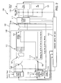
- Fig. 1 is an electrical machine architecture diagram for an electric start, electric power generation system (ES/EPGS).
- Electrical machine 100 includes a stator 102 including a main armature winding 104, an exciter field winding 105, and a transformer primary winding 106, e.g., an excitation coil.
- a rotor 108 is operatively connected to rotate relative to stator 102.
- Rotor 108 includes an exciter armature winding 107 operatively connected to exciter field winding 105 for field excitation therebetween, a main field winding 109 operatively connected to main armature winding 104 for field excitation therebetween, and a transformer secondary winding 110 operatively connected to transformer primary winding 106 to form a rotating transformer.
- a generator control unit 112 is operatively connected to main armature winding 104, exciter field winding 105, and transformer primary winding 106 to control the main armature and exciter field windings 104 and 105 based on excitation in transformer primary winding 106 received from transformer secondary winding 110.
- Generator control unit 112 is connected to direct external power through stator 102 to drive rotor 108 in a motoring mode and to deliver power from stator 102 to an external load in a generate mode.
- An AC power source 114 is operatively connected between generator control unit 112 and transformer primary winding 106 to control power to the rotating transformer.
- the transformer can be a high frequency rotating transformer (HFRT) designed to operate, for example from 1.0-40 kHz, or any other suitable frequency range subject to transformer size and EMI filter design considerations.
- a damper 116 is connected in parallel with transformer primary winding 106.
- AC power source 114 controls the excitation frequency in transformer secondary winding 110.
- external power can be routed through an AC/DC power source 111 to power exciter field winding 105 and through an AC power source and passive or active damper 116 to power transformer primary winding 106.
- Passive or active damper 116 is employed to reduce torsional oscillations of electrical machine 100 created by a distributed mechanical spring-mass system with torsional resonance.
- a rotating rectifier 113 connects between exciter armature winding 107 and main field winding 109.
- two parallel interface inductors 115 connect between rotating rectifier 113 and main field winding 109.
- Transformer secondary winding 110 is connected in parallel with main filed winding 109 between the interface inductors 115 and main field winding 109, and one of the connections of transformer secondary winding 110 includes a capacitor for blocking DC current from transformer secondary winding 110.
- the interface inductors 115 are used to decouple the high frequency transformer secondary winding 110 from the rotating rectifier 113.
- the high frequency current from the transformer secondary winding 110 is injected into the main field winding to be used in identification of rotor position as discussed below.
- FIG. 2 another possible connection between the transformer secondary winding 110 and main field winding 109 is shown.
- transformer secondary winding 110 connects through an interface capacitor to a point in the midst of the windings of main field winding 109 to be in parallel with only a portion of main field winding 109. Injecting high frequency current in the center-tap of the main field winding in this manner allows elimination of the interphase inductors.
- the other portions of electrical machine 100 shown in Fig. 2 are the same as shown in Fig. 1 .
- main armature winding 104 connects directly to generator control unit 112, and also connects to a three-phase current sensor 117, which in turn also connects with generator control unit 112.
- a start inverter 119 is connected to three-phase current sensor 117 in parallel with an AC load 121.
- external power can be routed through start inverter 119, which is controlled by generator control unit 112 to power main armature winding 117.
- power from main armature winding 104 can be delivered to AC load 121 by way of three-phase current sensor 117.
- Other aspects of traditional electrical machines employed in electrical machine 100 can be found, for example, in U.S. Patent No. 5,340,362 and U.S. Patent No. 5,488,286 .
- generator control unit 112 includes an electric engine start controller 123 and a generator voltage control and protection unit 125.
- start mode as selected by the mode selector, AC excitation power is enabled, high frequency AC power to the rotating transformer is enabled in electric engine start controller 123, the contactor (shown in Figs. 1 and 2 ) position is controlled to be in the start mode, damper 116 is disabled, and the start inverter is enabled by way of electric engine start controller 123.
- the speed reference e.g., programmable speed reference, allows optimization of the engine start by controlling acceleration rate of the engine, for example in starting a gas turbine engine using electrical machine 100.
- the start inverter is disabled by way of electric engine start controller 123, as is the high frequency AC power to the rotating transformer.
- the contactor position is controlled to be in the generate mode, and damper 116 is enabled.
- the AC voltage reference is provided to generator voltage control and protection unit 125, and DC excitation power is enabled.
- Electric engine start controller 123 outputs a signal to apply the high frequency AC power to the rotating transformer via transformer primary winding 106, and outputs a signal to control the start inverter power switches.
- Electric engine start controller 123 and generator voltage control and protection unit 125 both receive three-phase voltage and current signals at the output of main armature winding 104 in the generate mode.
- Voltage control and protection unit 125 outputs a control signal to control field current in exciter field winding 105.
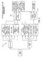
- electric engine start controller 123 includes a position and velocity decoder 118 connected to receive inverter voltage signals V a , V b , and V c and to output position and velocity feedback, designated pos_est and vel_est in Fig. 4 , respectively.
- a proportional and integral regulator, designated PI in Fig. 4 is included with a first switch 120 for switching between a velocity reference input for the motoring mode and a DC voltage reference for a generate mode.
- the PI also has a second switch 122 for switching between the velocity feedback and a DC voltage feedback input.
- the PI is configured to output a quadrature current reference signal, designated Iq_ref in Fig.
- a field oriented control (FOC) is operatively connected to receive the reference signals from the PI, the position feedback from position and velocity decoder 118, and inverter current signals I a , I b , and I c and to output stationary reference frame command signals Valpha_ref and Vbeta_ref.
- Quadrature generator 124 is connected to an AC power source to inject a signal, e.g., a sine signal, into the rotating transformer.
- the PWM converter shown in Fig. 4 operates as an engine start inverter during motoring mode and can be used as an active rectifier during the generate mode.
- FIG. 4 is a high level block diagram of an electric engine start controller, which includes a speed control function using a field-oriented controller (FOC) to control motor torque in response to the estimated rotor position.
- FOC field-oriented controller
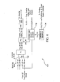
- position and velocity decoder 118 includes a Clark's Transformation component 126 operatively connected to convert the three phase inverter voltage signals V a , V b , and V c into two phase voltage signals Valpha and Vbeta.
- a pair of synchronous filters 128 and 130 are connected each to receive a respective one of the two phase voltage signals Valpha and Vbeta.
- Each of the synchronous filters 128 and 130 is also connected to receive sine and cosine signals from quadrature generator 124 and to output respective first and second filtered two phase voltage signals, VF_alpha and VF_beta, phase-shifted by 90 electrical degrees that contain rotor position information to position/velocity estimator 132.
- Position/velocity estimator 132 in turn outputs the position and velocity feedback, labeled pos_est and vel_est in Fig. 5 , which are also shown in Fig. 4 .
- Fig. 5 illustrates an embodiment using resolver-based signal processing to estimate rotor position from zero to high generator speed.
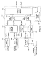
- Another embodiment that utilizes a zero/low speed position estimator and high speed position estimator based extended rotor flux is shown in Fig. 6 .
- Position and velocity decoder 218 includes a Clark's Transformation component 216 and synchronous filters 228 and 230 connected as described above with respect to Fig. 5 .
- position and velocity decoder 218 includes a second Clark's Transformation component 217 connected to convert the three phase/inverter current signals I a , I b , and I c , into two phase current signals Ialpha and Ibeta.
- An extended rotor flux estimator 234 is connected to receive the two phase current signals Ialpha and Ibeta and the two phase voltage signals Valpha and Vbeta and to output first and second extended flux voltage signals Fext_alpha and Fext_beta phase-shifted by 90 electrical degrees that contain extended rotor flux information.
- a position/velocity estimator 232 is included with a first switch 236 for switching between Fext_alpha input in a high speed mode and VF_alpha input in a low speed mode and a second switch 238 for switching between Fext_beta input in a high speed mode and VF_beta in a low speed mode.
- Position/velocity estimator 232 is configured to output the position feedback and the velocity feedback as described above.
- An estimated mode selector 240 is connected to receive the velocity feedback, labeled vel_est in Fig. 6 , and control the switches 236 and 238 of position/velocity estimator 232 for selection between the high and low speed modes.
- position and velocity decoder 218 operates the same as position and velocity decoder 118 of Fig. 5 .
- position and velocity decoder 218 can switch to operate based on extended rotor flux.
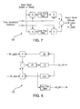
- a synchronous filter implementation and resolver-based signal processing for position and velocity estimation are shown in Figs. 7 and 8 . Additional details can be found in U.S. Patent No. 7,072,790 .
- Fig. 7 a block diagram of a synchronous filter 128 is shown.
- Synchronous filters 128, 130, 228, and 230 can all be of the same configuration as that shown in Fig. 7 .
- Synchronous filters select voltage components Valpha and Vbeta that contain rotor position information and are synchronized with the signals from the quadrature generator.
- Fig. 8 a block diagram of the position/velocity estimator 132 of Fig. 5 is shown.
- the same phase-locked loop configuration can be used for the position velocity/estimator 232 of Fig. 6 , the difference being that position velocity/estimator 232 connects to its inputs through switches 236 and 238.
- An exemplary method of controlling an electrical machine includes receiving an excitation signal with a primary transformer winding of the electrical machine.
- the position and velocity of the rotor can be estimated by separating the excitation coil signal and the signal of the exciter field and armature windings and using estimated position and velocity of the rotor to control the electrical machine using a generator control unit, e.g., generator control unit 112 described above in.
- Using estimated position and velocity of the rotor to control the electrical machine can include controlling rotor toque in a motoring mode and controlling output voltage in a generate mode.
- the Electric Start / Electric Power Generating System (ES/EPGS) architecture illustrated in Fig. 1 includes a modified Wound Field Synchronous Machine (WFSM) that includes a single phase high frequency rotating transformer (HFRT).
- WFSM Wound Field Synchronous Machine
- the HFRT is connected via interface capacitor to the rotating DC bus that feeds the main field winding.
- the purpose of the HFRT is to inject a small AC signal into the main field winding.
- the interface capacitor prevents the HFRT secondary winding from being connected directly to the DC bus to avoid magnetic saturation of the core.
- the interface inductors reduce circulating current through the rotating rectifier diodes at injected high frequency.
- FIG. 2 Another embodiment is shown in Fig. 2 with an AC signal injected in the center tap of main field winding.
- the WFSM with field injected AC signal operates as a synchro at the injected frequency.
- the 3-wire synchro output can be easily converted into the resolver-equivalent format using Clark's 3-phase to 2-phase transformation (ABC to ⁇ ⁇ stationary reference frames).
- the AC signal that contains rotor position information can be selected using synchronous filter which is synchronized with the quadrature generator that is used to inject the AC signal into the field winding, as indicated in Fig. 5 .
- the HFRT can also play a useful role in a generate mode by providing alternative current path during overvoltage conditions.
- the primary winding of the HFRT is connected to the passive damper (resistor) or active damper such as a voltage control resistor (FET).
- FET voltage control resistor
- a single phase inverter can be also utilized to inject a pulse into main field winding in coordination with the generator voltage regulator.
- the synchronous exciter is configured as a three-phase Low Frequency Rotating Transformer (LFRT) to pass excitation power at zero and low rotor peed rotor to the main field winding.
- LFRT Low Frequency Rotating Transformer
- LFRT can operate at 400 - 1000 Hz during engine start mode.
- the exciter is configured as a single phase exciter feld winding operating at DC current.
- FIG. 4 A high level block diagram of electric engine start controller is shown in Fig. 4 and includes a speed control function using field-oriented controller (FOC) to control motor torque in response to the estimated rotor position.
- Fig. 5 illustrates an embodiment using resolver-based signal processing to estimate rotor position from zero to high generator speed.
- FIG. 6 Another embodiment that utilizes zero/low speed position estimator and high speed position estimator based extended rotor flux is shown in Fig. 6 .
- the methods and systems described herein offer potential benefits including improved system performance and reliability when operating as an active rectifier due to improved position sensing accuracy. Additional potential benefits include improved system complexity and cost, potential damping of rotor oscillations at variable load and improved stability, improved power density when a smaller size machine is used for electric pumps or actuators, and potential reduction in size of power semiconductors when used as electric engine start due to improved accuracy in rotor position sensing.
- the transient response during overvoltage events may also be improved by providing a transient alternative path to the main field current. Further improvement in the generator dynamic performance may be facilitated by controlling voltage across the main field winding using a high frequency rotating transformer.
Abstract
Description
- The present invention relates to electrical machines such as motors and generators, and more particularly to angular position and velocity estimation of wound field synchronous machines (WFSM).
- Electrical machines can be used as motors or as generators. In aeronautical applications, for example, it is desirable to use a single machine for a starter motor and a generator to reduce size and weight. An aircraft generator can be used as a motor to start the propulsion engine for the aircraft when it is powered by an inverter.
- To reduce cost and improve reliability, it is very desirable for the engine starter to eliminate mechanical shaft sensors. In general, there are two categories in sensorless motor control, the back EMF based method and the signal injection method. The back EMF based method is easy to implement, and usually works quite well at high angular rotor velocity, but it is inadequate for low velocity or standstill. The signal injection method is more difficult to implement, but can be advantageous for operation at low angular rotor velocity or standstill. Most systems that utilize the signal injection method are also subject to a 180 degree rotor position anomaly because these systems are not able to recognize if they are locking onto the positive or negative pole of the rotor.
- Such conventional methods and systems have generally been considered satisfactory for their intended purpose. However, there is still a need in the art for systems and methods that allow for improved performance such as reliability, complexity, and cost. There also remains a need in the art for such systems and methods that are easy to make and use. The present disclosure provides a solution for these problems.
- An electrical machine includes a stator including a main armature winding, an exciter field winding, and a transformer primary winding. A rotor is operatively connected to rotate relative to the stator, wherein the rotor includes an exciter armature winding operatively connected to the exciter field winding for field excitation therebetween, a main field winding operatively connected to the main armature winding for field excitation therebetween, and a transformer secondary winding operatively connected to the transformer primary winding to form a rotating transformer. A generator control unit is operatively connected to the main armature winding, exciter field winding, and transformer primary winding to control the main armature and exciter field windings based on excitation in the transformer primary winding received from the transformer secondary winding.
- The generator control unit can be configured to direct external power through the stator to drive the rotor in a motoring mode and to deliver power from the stator to an external load in a generate mode. An AC power source can be operatively connected between the generator control unit and the transformer primary winding to control power to the rotating transformer. A damper can be connected in parallel with the transformer primary winding.
- In certain embodiments, the generator control unit includes an electric engine start controller having a position and velocity decoder configured and adapted to receive inverter voltage signals and to output position and velocity feedback. A proportional and integral regulator is included with a first switch for switching between a velocity reference input for the motoring mode and a DC voltage reference for a generate mode, and a second switch for switching between the velocity feedback and a DC voltage feedback input. The proportional and integral regulator is configured to output a quadrature current reference signal in the motoring mode and a direct current reference signal in the generate mode. A field oriented control is operatively connected to receive the reference signals from the proportional and integral regulator, the position feedback from the position and velocity decoder, and inverter current signals and to output stationary reference frame command signals.
- It is contemplated that a quadrature generator can be operatively connected to an AC power source to inject a signal, e.g., a sine signal, into the rotating transformer. The position and velocity decoder can include a Clark's Transformation component operatively connected to convert three phase inverter voltage signals into two phase voltage signals. A pair of synchronous filters can each be operatively connected to receive a respective one of the two phase voltage signals. Each synchronous filter can also be operatively connected to receive sine and cosine signals from a quadrature generator and to output first and second filtered two phase voltage signals phase-shifted by 90 electrical degrees that contain rotor position information.
- In certain embodiments a second Clark's Transformation component is operatively connected to convert three phase inverter current signals into two phase current signals and an extended rotor flux estimator is operatively connected to receive the two phase current signals and the two phase voltage signals and to output first and second extended flux voltage signals phase-shifted by 90 electrical degrees that contain extended rotor flux information. A position/velocity estimator can be included with a first switch for switching between a first extended flux voltage input in a high speed mode and a first filtered two phase voltage signal input in a low speed mode and a second switch for switching between a second extended flux voltage signal input in a high speed mode and a second filtered two phase voltage signal in a low speed mode. The position/velocity estimator is configured to output the position feedback and the velocity feedback. An estimated mode selector can be operatively connected to receive the velocity feedback and control the first and second switches of the position/velocity estimator for selection between the high and low speed modes.
- A method of controlling an electrical machine includes receiving an excitation signal with a primary transformer winding of an electrical machine such as described above. The method also includes estimating position and velocity of the rotor based on the excitation signal and using estimated position and velocity of the rotor to control the electrical machine. Using estimated position and velocity of the rotor to control the electrical machine can include controlling rotor toque in a motoring mode and controlling output voltage in a generate mode.
- These and other features of the systems and methods of the subject disclosure will become more readily apparent to those skilled in the art from the following detailed description of the preferred embodiments taken in conjunction with the drawings.
- So that those skilled in the art to which the subject disclosure appertains will readily understand how to make and use the devices and methods of the subject disclosure without undue experimentation, preferred embodiments thereof will be described in detail herein below by way of example only and with reference to certain figures, wherein:
-
Fig. 1 is a schematic view of an exemplary embodiment of an electrical machine system architecture, showing the high frequency rotating transformer; -
Fig. 2 is a schematic view of another exemplary embodiment of an electrical machine system architecture, showing a high frequency rotating transformer with a connection to the main field winding that differs from that shown inFig. 1 ; -
Fig. 3 is a block diagram of an exemplary embodiment of a generator control unit (GCU) for use with the system architectures ofFigs. 1 and2 , showing the electric engine start controller; -
Fig. 4 is a block diagram of an exemplary embodiment of the electric engine start controller ofFig. 3 , showing the inputs and outputs for use in determining rotor position and velocity for the motoring and generate modes, and also showing the position and velocity decoder; -
Fig. 5 is a block diagram of an exemplary embodiment of the position and velocity decoder ofFig. 4 , showing the synchronous filters and the position/velocity estimator; -
Fig. 6 is a block diagram of another exemplary embodiment of a position and velocity decoder ofFig. 4 , showing an extended rotor flux estimator; -
Fig. 7 is a block diagram of an exemplary embodiment of one of the synchronous filters shown inFigs. 5 and6 ; and -
Fig. 8 is a block diagram of an exemplary embodiment of a position and velocity estimator shown inFig. 5 . - Reference will now be made to the drawings wherein like reference numerals identify similar structural features or aspects of the subject disclosure. For purposes of explanation and illustration, and not limitation, a partial view of an exemplary embodiment of an electrical machine is shown in
Fig. 1 and is designated generally byreference character 100. Other embodiments of electrical machines, or aspects thereof, are provided inFigs. 2-8 , as will be described. The systems and methods of the disclosure can be used, for example, to completely eliminate the resolver as a position sensor for electric engine start and active rectification commutation to improve system reliability, complexity, and cost without necessarily reducing power density. -
Fig. 1 is an electrical machine architecture diagram for an electric start, electric power generation system (ES/EPGS).Electrical machine 100 includes astator 102 including a main armature winding 104, an exciter field winding 105, and a transformerprimary winding 106, e.g., an excitation coil. Arotor 108 is operatively connected to rotate relative tostator 102.Rotor 108 includes an exciter armature winding 107 operatively connected to exciterfield winding 105 for field excitation therebetween, a main field winding 109 operatively connected to main armature winding 104 for field excitation therebetween, and a transformersecondary winding 110 operatively connected to transformerprimary winding 106 to form a rotating transformer. - A
generator control unit 112 is operatively connected to main armature winding 104,exciter field winding 105, and transformerprimary winding 106 to control the main armature and exciterfield windings primary winding 106 received from transformersecondary winding 110.Generator control unit 112 is connected to direct external power throughstator 102 to driverotor 108 in a motoring mode and to deliver power fromstator 102 to an external load in a generate mode. - An
AC power source 114 is operatively connected betweengenerator control unit 112 and transformerprimary winding 106 to control power to the rotating transformer. The transformer can be a high frequency rotating transformer (HFRT) designed to operate, for example from 1.0-40 kHz, or any other suitable frequency range subject to transformer size and EMI filter design considerations. Adamper 116 is connected in parallel with transformerprimary winding 106.AC power source 114 controls the excitation frequency in transformersecondary winding 110. - As also indicated in
Fig. 1 , external power can be routed through an AC/DC power source 111 to power exciter field winding 105 and through an AC power source and passive oractive damper 116 to power transformerprimary winding 106. Passive oractive damper 116 is employed to reduce torsional oscillations ofelectrical machine 100 created by a distributed mechanical spring-mass system with torsional resonance. A rotatingrectifier 113 connects between exciter armature winding 107 and main field winding 109. Additionally, twoparallel interface inductors 115 connect between rotatingrectifier 113 and main field winding 109. Transformersecondary winding 110 is connected in parallel with main filed winding 109 between theinterface inductors 115 and main field winding 109, and one of the connections of transformersecondary winding 110 includes a capacitor for blocking DC current from transformersecondary winding 110. Theinterface inductors 115 are used to decouple the high frequency transformersecondary winding 110 from the rotatingrectifier 113. The high frequency current from the transformersecondary winding 110 is injected into the main field winding to be used in identification of rotor position as discussed below. - Referring to
Fig. 2 , another possible connection between the transformer secondary winding 110 and main field winding 109 is shown. InFig. 2 , there are no interface inductors, and transformer secondary winding 110 connects through an interface capacitor to a point in the midst of the windings of main field winding 109 to be in parallel with only a portion of main field winding 109. Injecting high frequency current in the center-tap of the main field winding in this manner allows elimination of the interphase inductors. The other portions ofelectrical machine 100 shown inFig. 2 are the same as shown inFig. 1 . - Referring again to
Fig. 1 , main armature winding 104 connects directly togenerator control unit 112, and also connects to a three-phasecurrent sensor 117, which in turn also connects withgenerator control unit 112. Astart inverter 119 is connected to three-phasecurrent sensor 117 in parallel with anAC load 121. In the motoring mode, external power can be routed throughstart inverter 119, which is controlled bygenerator control unit 112 to power main armature winding 117. In the generate mode, power from main armature winding 104 can be delivered to AC load 121 by way of three-phasecurrent sensor 117. Other aspects of traditional electrical machines employed inelectrical machine 100 can be found, for example, inU.S. Patent No. 5,340,362 andU.S. Patent No. 5,488,286 . - Referring now to
Fig. 3 ,generator control unit 112 includes an electricengine start controller 123 and a generator voltage control andprotection unit 125. In the start mode, as selected by the mode selector, AC excitation power is enabled, high frequency AC power to the rotating transformer is enabled in electricengine start controller 123, the contactor (shown inFigs. 1 and2 ) position is controlled to be in the start mode,damper 116 is disabled, and the start inverter is enabled by way of electricengine start controller 123. During start mode the speed reference, e.g., programmable speed reference, allows optimization of the engine start by controlling acceleration rate of the engine, for example in starting a gas turbine engine usingelectrical machine 100. Similarly in the generate mode, the start inverter is disabled by way of electricengine start controller 123, as is the high frequency AC power to the rotating transformer. The contactor position is controlled to be in the generate mode, anddamper 116 is enabled. The AC voltage reference is provided to generator voltage control andprotection unit 125, and DC excitation power is enabled. Electricengine start controller 123 outputs a signal to apply the high frequency AC power to the rotating transformer via transformer primary winding 106, and outputs a signal to control the start inverter power switches. Electricengine start controller 123 and generator voltage control andprotection unit 125 both receive three-phase voltage and current signals at the output of main armature winding 104 in the generate mode. Voltage control andprotection unit 125 outputs a control signal to control field current in exciter field winding 105. - Referring now to
Fig. 4 , electricengine start controller 123 includes a position andvelocity decoder 118 connected to receive inverter voltage signals Va, Vb, and Vc and to output position and velocity feedback, designated pos_est and vel_est inFig. 4 , respectively. A proportional and integral regulator, designated PI inFig. 4 , is included with afirst switch 120 for switching between a velocity reference input for the motoring mode and a DC voltage reference for a generate mode. The PI also has asecond switch 122 for switching between the velocity feedback and a DC voltage feedback input. The PI is configured to output a quadrature current reference signal, designated Iq_ref inFig. 4 , and a direct current reference signal, Id_ref inFig. 4 , in both the motoring and generate modes. A field oriented control (FOC) is operatively connected to receive the reference signals from the PI, the position feedback from position andvelocity decoder 118, and inverter current signals Ia, Ib, and Ic and to output stationary reference frame command signals Valpha_ref and Vbeta_ref.Quadrature generator 124 is connected to an AC power source to inject a signal, e.g., a sine signal, into the rotating transformer. The PWM converter shown inFig. 4 operates as an engine start inverter during motoring mode and can be used as an active rectifier during the generate mode. -
Electrical machine 100 with the AC signal injected in the excitation coil, i.e. transformer secondary winding 110, operates as a synchro at the injected frequency. The 3-wire synchro output can be easily converted into the resolver-equivalent format using Clark's 3-phase to 2-phase transformation (ABC to α β stationary reference frames). The AC signal that contains rotor position information can be selected using synchronous filters which are synchronized with the quadrature generator that is used to inject ac signal into field winding.Fig. 4 is a high level block diagram of an electric engine start controller, which includes a speed control function using a field-oriented controller (FOC) to control motor torque in response to the estimated rotor position. - Referring now to
Fig. 5 , position andvelocity decoder 118 includes a Clark'sTransformation component 126 operatively connected to convert the three phase inverter voltage signals Va, Vb, and Vc into two phase voltage signals Valpha and Vbeta. A pair ofsynchronous filters synchronous filters quadrature generator 124 and to output respective first and second filtered two phase voltage signals, VF_alpha and VF_beta, phase-shifted by 90 electrical degrees that contain rotor position information to position/velocity estimator 132. Position/velocity estimator 132 in turn outputs the position and velocity feedback, labeled pos_est and vel_est inFig. 5 , which are also shown inFig. 4 . -
Fig. 5 illustrates an embodiment using resolver-based signal processing to estimate rotor position from zero to high generator speed. Another embodiment that utilizes a zero/low speed position estimator and high speed position estimator based extended rotor flux is shown inFig. 6 . - Making reference now to
Fig. 6 , a second embodiment of a position andvelocity decoder 218 is shown, which can be used ingenerator control unit 112 ofFig. 4 in lieu of position andvelocity decoder 118. Position andvelocity decoder 218 includes a Clark'sTransformation component 216 andsynchronous filters Fig. 5 . In addition, position andvelocity decoder 218 includes a second Clark'sTransformation component 217 connected to convert the three phase/inverter current signals Ia, Ib, and Ic, into two phase current signals Ialpha and Ibeta. An extendedrotor flux estimator 234 is connected to receive the two phase current signals Ialpha and Ibeta and the two phase voltage signals Valpha and Vbeta and to output first and second extended flux voltage signals Fext_alpha and Fext_beta phase-shifted by 90 electrical degrees that contain extended rotor flux information. - A position/
velocity estimator 232 is included with afirst switch 236 for switching between Fext_alpha input in a high speed mode and VF_alpha input in a low speed mode and a second switch 238 for switching between Fext_beta input in a high speed mode and VF_beta in a low speed mode. Position/velocity estimator 232 is configured to output the position feedback and the velocity feedback as described above. An estimatedmode selector 240 is connected to receive the velocity feedback, labeled vel_est inFig. 6 , and control theswitches 236 and 238 of position/velocity estimator 232 for selection between the high and low speed modes. In the low speed mode, position andvelocity decoder 218 operates the same as position andvelocity decoder 118 ofFig. 5 . In the high speed mode, position andvelocity decoder 218 can switch to operate based on extended rotor flux. - Details of a synchronous filter implementation and resolver-based signal processing for position and velocity estimation are shown in
Figs. 7 and 8 . Additional details can be found inU.S. Patent No. 7,072,790 . Referring toFig. 7 , a block diagram of asynchronous filter 128 is shown.Synchronous filters Fig. 7 . Synchronous filters select voltage components Valpha and Vbeta that contain rotor position information and are synchronized with the signals from the quadrature generator. With reference toFig. 8 , a block diagram of the position/velocity estimator 132 ofFig. 5 is shown. The same phase-locked loop configuration can be used for the position velocity/estimator 232 ofFig. 6 , the difference being that position velocity/estimator 232 connects to its inputs throughswitches 236 and 238. - An exemplary method of controlling an electrical machine, e.g.,
electrical machine 100, includes receiving an excitation signal with a primary transformer winding of the electrical machine. The position and velocity of the rotor can be estimated by separating the excitation coil signal and the signal of the exciter field and armature windings and using estimated position and velocity of the rotor to control the electrical machine using a generator control unit, e.g.,generator control unit 112 described above in. Using estimated position and velocity of the rotor to control the electrical machine can include controlling rotor toque in a motoring mode and controlling output voltage in a generate mode. - The Electric Start / Electric Power Generating System (ES/EPGS) architecture illustrated in
Fig. 1 includes a modified Wound Field Synchronous Machine (WFSM) that includes a single phase high frequency rotating transformer (HFRT). The HFRT is connected via interface capacitor to the rotating DC bus that feeds the main field winding. The purpose of the HFRT is to inject a small AC signal into the main field winding. The interface capacitor prevents the HFRT secondary winding from being connected directly to the DC bus to avoid magnetic saturation of the core. The interface inductors reduce circulating current through the rotating rectifier diodes at injected high frequency. Another embodiment is shown inFig. 2 with an AC signal injected in the center tap of main field winding. - During start mode the WFSM with field injected AC signal operates as a synchro at the injected frequency. The 3-wire synchro output can be easily converted into the resolver-equivalent format using Clark's 3-phase to 2-phase transformation (ABC to α β stationary reference frames). The AC signal that contains rotor position information can be selected using synchronous filter which is synchronized with the quadrature generator that is used to inject the AC signal into the field winding, as indicated in
Fig. 5 . - The HFRT can also play a useful role in a generate mode by providing alternative current path during overvoltage conditions. In this mode the primary winding of the HFRT is connected to the passive damper (resistor) or active damper such as a voltage control resistor (FET). A single phase inverter can be also utilized to inject a pulse into main field winding in coordination with the generator voltage regulator.
- During engine start the synchronous exciter is configured as a three-phase Low Frequency Rotating Transformer (LFRT) to pass excitation power at zero and low rotor peed rotor to the main field winding. LFRT can operate at 400 - 1000 Hz during engine start mode. During generate mode the exciter is configured as a single phase exciter feld winding operating at DC current.
- A high level block diagram of electric engine start controller is shown in
Fig. 4 and includes a speed control function using field-oriented controller (FOC) to control motor torque in response to the estimated rotor position.Fig. 5 illustrates an embodiment using resolver-based signal processing to estimate rotor position from zero to high generator speed. Another embodiment that utilizes zero/low speed position estimator and high speed position estimator based extended rotor flux is shown inFig. 6 . - The methods and systems described herein offer potential benefits including improved system performance and reliability when operating as an active rectifier due to improved position sensing accuracy. Additional potential benefits include improved system complexity and cost, potential damping of rotor oscillations at variable load and improved stability, improved power density when a smaller size machine is used for electric pumps or actuators, and potential reduction in size of power semiconductors when used as electric engine start due to improved accuracy in rotor position sensing. The transient response during overvoltage events may also be improved by providing a transient alternative path to the main field current. Further improvement in the generator dynamic performance may be facilitated by controlling voltage across the main field winding using a high frequency rotating transformer.
- While shown and described in the exemplary context of a starter/DC power generating system, those skilled in the art will readily appreciate that such applications are exemplary only, ant that any other suitable applications can be used without departing from the scope of the invention.
- The methods and systems described above and shown in the drawings, provide for electrical machine systems and methods with superior properties including, for example, improved system reliability, complexity, and cost without necessarily reducing power density. While the apparatus and methods of the subject disclosure have been shown and described with reference to preferred embodiments, those skilled in the art will readily appreciate that changes and/or modifications may be made thereto without departing from the scope of the subject invention, which is defined by the claims.
- The following clauses set out features of the invention which may not presently be claimed in this application, but which may form the basis for future amendment or a divisional application.
- 1. An electrical machine comprising:
- a stator including a main armature winding, an exciter field winding, and a transformer primary winding;
- a rotor operatively connected to rotate relative to the stator, wherein the rotor includes an exciter armature winding operatively connected to the exciter armature winding for field excitation therebetween, a main field winding operatively connected to the main armature winding for field excitation therebetween, and a transformer secondary winding operatively connected to the transformer primary winding to form a rotating transformer; and
- a generator control unit operatively connected to the main armature winding, exciter field winding, and transformer primary winding to control the main armature and exciter field windings based on excitation in the transformer primary winding received from the transformer secondary winding.
- 2. An electrical machine as recited in
clause 1, further comprising an AC power source operatively connected between the generator control unit and the transformer primary winding to control power to the rotating transformer. - 3. An electrical machine as recited in
clause 1, further comprising a damper connected in parallel with the transformer primary winding. - 4. An electrical machine as recited in
clause 1, wherein the generator control unit is configured to direct external power through the stator to drive the rotor in a motoring mode and to deliver power from the stator to an external load in a generate mode. - 5. An electrical machine as recited in clause 4, wherein the generator control unit includes an electric engine start controller having:
- a position and velocity decoder configured and adapted to receive inverter voltage signals and to output position and velocity feedback;
- a proportional and integral regulator with a first switch for switching between a velocity reference input for the motoring mode and a DC voltage reference for a generate mode, and a second switch for switching between the velocity feedback and a DC voltage feedback input, wherein the proportional and integral regulator is configured to output a quadrature current reference signal and a direct current reference signal in both the motoring and generate modes; and
- a field oriented control operatively connected to receive the reference signals from the proportional and integral regulator, the position feedback from the position and velocity decoder, and inverter current signals and to output stationary reference frame command signals.
- 6. An electrical machine as recited in clause 5, further comprising a quadrature generator operatively connected to an AC power source to inject a sine signal into the rotating transformer.
- 7. An electrical machine as recited in clause 5, wherein the position and velocity decoder includes a Clark's Transformation component operatively connected to convert three phase inverter voltage signals into two phase voltage signals, with a pair of synchronous filters each operatively connected to receive a respective one of the two phase voltage signals, each synchronous filter being operatively connected to receive sine and cosine signals from a quadrature generator and to output first and second filtered two phase voltage signals phase-shifted by 90 electrical degrees that include rotor position information.
- 8. An electrical machine as recited in clause 7, further comprising a position/velocity estimator operatively connected to receive first and second filtered two phase voltage signals from the synchronous filters and to output the position feedback and the velocity feedback.
- 9. An electrical machine as recited in clause 7, further comprising:
- a second Clark's Transformation component operatively connected to convert three phase inverter current signals into two phase current signals; and
- an extended rotor flux estimator operatively connected to receive the two phase current signals and the two phase voltage signals and to output first and second extended flux voltage signals phase-shifted by 90 electrical degrees that include extended rotor flux information.
- 10. An electrical machine as recited in clause 9, further comprising a position/velocity estimator with a first switch for switching between the first extended flux voltage signal input in a high speed mode and the first filtered two phase voltage signal input in a low speed mode and a second switch for switching between the second extended flux voltage signal input in a high speed mode and the second filtered two phase voltage signal in a low speed mode, wherein the position/velocity estimator is configured to output the position feedback and the velocity feedback.
- 11. An electrical machine as recited in clause 10, further comprising an estimated mode selector operatively connected to receive the velocity feedback and control the first and second switches of the position/velocity estimator for selection between the high and low speed modes.
- 12. A generator control unit for controlling a main armature and exciter field winding of a stator to drive a rotor in a motoring mode and to deliver power from the stator to an external load in a generate mode, the generator control unit comprising:
- a position and velocity decoder configured and adapted to receive inverter voltage signals and to output position and velocity feedback;
- a proportional and integral regulator with a first switch for switching between a velocity reference input for the motoring mode and a DC voltage reference for a generate mode, and a second switch for switching between the velocity feedback and a DC voltage feedback input, wherein the proportional and integral regulator is configured to output a quadrature current reference signal and a direct current reference signal in both the motoring and generate modes; and
- a field oriented control operatively connected to receive the reference signals from the proportional and integral regulator, the position feedback from the position and velocity decoder, and inverter current signals and to output stationary reference frame command signals.
- 13. A generator control unit as recited in clause 12, further comprising a quadrature generator operatively connected to an AC power source to inject a sine quadrature signal into an excitation coil.
- 14. A generator control unit as recited in clause 12, wherein the position and velocity decoder includes a Clark's Transformation component operatively connected to convert three phase inverter voltage signals into two phase voltage signals, with a pair of synchronous filters each operatively connected to receive a respective one of the two phase voltage signals, each synchronous filter being operatively connected to receive sine and cosine signals from a quadrature generator and to output first and second filtered two phase voltage signals phase-shifted by 90 electrical degrees that include rotor position information.
- 15. A generator control unit as recited in clause 14, further comprising a position/velocity estimator operatively connected to receive the first and second filtered two phase voltage signals from the synchronous filters and to output the position feedback and the velocity feedback.
- 16. A generator control unit as recited in clause 14, further comprising:
- a second Clark's Transformation component operatively connected to convert three phase inverter current signals into two phase current signals; and
- an extended rotor flux estimator operatively connected to receive the two phase current signals and the two phase voltage signals and to output first and second extended flux voltage signals phase-shifted by 90 electrical degrees that include extended rotor flux information.
- 17. A generator control unit as recited in clause 16, further comprising a position/velocity estimator with a first switch for switching between the first extended flux voltage signal input in a high speed mode and the first filtered two phase voltage signal input in a low speed mode and a second switch for switching between the second extended flux voltage signal input in a high speed mode and the second filtered two phase voltage signal in a low speed mode, wherein the position/velocity estimator is configured to output the position feedback and the velocity feedback.
- 18. A generator control unit as recited in clause 17, further comprising an estimated mode selector operatively connected to receive the velocity feedback and control the first and second switches of the position velocity/estimator for selection between the high and low speed modes.
- 19. A method of controlling an electrical machine comprising:
- receiving an excitation signal with a primary transformer winding of an electrical machine as recited in
clause 1; and - estimating position and velocity of the rotor based on the excitation signal; and
- using estimated position and velocity of the rotor to control the electrical machine.
- receiving an excitation signal with a primary transformer winding of an electrical machine as recited in
- 20. A method as recited in clause 19, wherein using estimated position and velocity of the rotor to control the electrical machine includes controlling rotor torque in a motoring mode and controlling output voltage in a generate mode.
Claims (15)
- An electrical machine (100) comprising:a stator (102) including a main armature winding (104), an exciter field winding (105), and a transformer primary winding (106);a rotor (108) operatively connected to rotate relative to the stator, wherein the rotor includes an exciter armature winding (107) operatively connected to the exciter field winding for field excitation therebetween, a main field winding (109) operatively connected to the main armature winding for field excitation therebetween, and a transformer secondary winding (110) operatively connected to the transformer primary winding to form a rotating transformer; anda generator control unit (112) operatively connected to the main armature winding, exciter field winding, and transformer primary winding to control the main armature and exciter field windings based on excitation in the transformer primary winding received from the transformer secondary winding.
- An electrical machine as recited in claim 1, further comprising an AC power source (114) operatively connected between the generator control unit and the transformer primary winding to control power to the rotating transformer.
- An electrical machine as recited in claim 1 or 2, further comprising a damper (116) connected in parallel with the transformer primary winding.
- An electrical machine as recited in claim 1, 2 or 3, wherein the generator control unit is configured to direct external power through the stator to drive the rotor in a motoring mode and to deliver power from the stator to an external load in a generate mode.
- An electrical machine as recited in claim 4, wherein the generator control unit includes an electric engine start controller (123) having:a position and velocity decoder (118) configured and adapted to receive inverter voltage signals (Va, Vb, Vc) and to output position and velocity feedback (pos_est, vel_est);a proportional and integral regulator (PI) with a first switch for switching between a velocity reference input for the motoring mode and a DC voltage reference for a generate mode, and a second switch for switching between the velocity feedback and a DC voltage feedback input, wherein the proportional and integral regulator is configured to output a quadrature current reference signal (Iq_ref) and a direct current reference signal (Id_ref) in both the motoring and generate modes; anda field oriented control (FOC) operatively connected to receive the reference signals from the proportional and integral regulator, the position feedback from the position and velocity decoder, and inverter current signals and to output stationary reference frame command signals (Valpha_ref, Vbeta_ref).
- An electrical machine as recited in claim 5, further comprising a quadrature generator (124) operatively connected to an AC power source to inject a sine signal into the rotating transformer.
- A generator control unit (112) for controlling a main armature winding (104) and exciter field winding (105) of a stator (102) to drive a rotor (108) in a motoring mode and to deliver power from the stator to an external load in a generate mode, the generator control unit comprising:a position and velocity decoder (118) configured and adapted to receive inverter voltage signals (Va, Vb, Vc) and to output position and velocity feedback (pos_est, vel_est);a proportional and integral regulator (PI) with a first switch for switching between a velocity reference input for the motoring mode and a DC voltage reference for a generate mode, and a second switch for switching between the velocity feedback and a DC voltage feedback input, wherein the proportional and integral regulator is configured to output a quadrature current reference signal (Iq_ref) and a direct current reference signal (Id_ref) in both the motoring and generate modes; anda field oriented control (FOC) operatively connected to receive the reference signals from the proportional and integral regulator, the position feedback from the position and velocity decoder, and inverter current signals and to output stationary reference frame command signals (Valpha_ref, Vbeta_ref).
- A generator control unit as recited in claim 7, further comprising a quadrature generator (124) operatively connected to an AC power source to inject a sine quadrature signal into an excitation coil.
- An electrical machine or a generator control unit as recited in claim 5, 6, 7 or 8, wherein the position and velocity decoder includes a Clark's Transformation component (126) operatively connected to convert three phase inverter voltage signals into two phase voltage signals, with a pair of synchronous filters each operatively connected to receive a respective one of the two phase voltage signals (Valpha, Vbeta), each synchronous filter (128, 130) being operatively connected to receive sine and cosine signals from a quadrature generator (124) and to output first and second filtered two phase voltage signals phase-shifted by 90 electrical degrees that include rotor position information.
- An electrical machine or a generator control unit as recited in claim 9, further comprising a position/velocity estimator (232) operatively connected to receive the first and second filtered two phase voltage signals from the synchronous flters and to output the position feedback and the velocity feedback.
- An electrical machine generator control unit as recited in claim 9, further comprising:a second Clark's Transformation component (127) operatively connected to convert three phase inverter current signals into two phase current signals; andan extended rotor flux estimator (234) operatively connected to receive the two phase current signals and the two phase voltage signals and to output first and second extended flux voltage signals phase-shifted by 90 electrical degrees that include extended rotor flux information.
- An electrical machine or a generator control unit as recited in claim 11, further comprising a position/velocity (232) estimator with a first switch for switching between the first extended flux voltage signal input in a high speed mode and the first filtered two phase voltage signal input in a low speed mode and a second switch for switching between the second extended flux voltage signal input in a high speed mode and the second filtered two phase voltage signal in a low speed mode, wherein the position/velocity estimator is configured to output the position feedback and the velocity feedback.
- An electrical machine or a generator control unit as recited in claim 12, further comprising an estimated mode selector (240) operatively connected to receive the velocity feedback and control the first and second switches of the position velocity/estimator for selection between the high and low speed modes.
- A method of controlling an electrical machine comprising:receiving an excitation signal with a primary transformer winding (106) of an electrical machine (100) as recited in any of claims 1 to 6 or 9 to 13; andestimating position and velocity of the rotor based on the excitation signal; andusing estimated position and velocity of the rotor to control the electrical machine.
- A method as recited in claim 14, wherein using estimated position and velocity of the rotor to control the electrical machine includes controlling rotor torque in a motoring mode and controlling output voltage in a generate mode.
Applications Claiming Priority (1)
| Application Number | Priority Date | Filing Date | Title |
|---|---|---|---|
| US13/958,169 US8928293B1 (en) | 2013-08-02 | 2013-08-02 | Systems for wound field synchronous machines with zero speed rotor position detection during start for motoring and improved transient response for generation |
Publications (3)
| Publication Number | Publication Date |
|---|---|
| EP2840702A2 true EP2840702A2 (en) | 2015-02-25 |
| EP2840702A3 EP2840702A3 (en) | 2015-07-15 |
| EP2840702B1 EP2840702B1 (en) | 2020-02-26 |
Family
ID=51224814
Family Applications (1)
| Application Number | Title | Priority Date | Filing Date |
|---|---|---|---|
| EP14178531.1A Active EP2840702B1 (en) | 2013-08-02 | 2014-07-25 | Systems for wound field synchronous machines with zero speed rotor position detection during start for motoring and improved transient response for generation |
Country Status (2)
| Country | Link |
|---|---|
| US (1) | US8928293B1 (en) |
| EP (1) | EP2840702B1 (en) |
Cited By (3)
| Publication number | Priority date | Publication date | Assignee | Title |
|---|---|---|---|---|
| WO2018048129A1 (en) * | 2016-09-09 | 2018-03-15 | 한온시스템 주식회사 | Motor rotor controlling apparatus and method |
| GB2578433A (en) * | 2018-10-25 | 2020-05-13 | Safran Electrical & Power | Electric machine control |
| EP3667896A1 (en) * | 2018-12-10 | 2020-06-17 | The Boeing Company | Negative-slope voltage-frequency for starting a variable frequency independent speed motor and speed control |
Families Citing this family (13)
| Publication number | Priority date | Publication date | Assignee | Title |
|---|---|---|---|---|
| US9088230B2 (en) * | 2012-06-01 | 2015-07-21 | Hamilton Sundstrand Corporation | Dual generator system |
| GB2504754B (en) * | 2012-08-09 | 2018-07-04 | Safran Power Uk Ltd | Aircraft engine electrical apparatus |
| US9257889B2 (en) * | 2013-03-15 | 2016-02-09 | Hamilton Sundstrand Corporation | EPGS architecture with multi-channel synchronous generator and common field regulated exciter |
| US9252695B2 (en) * | 2014-03-12 | 2016-02-02 | General Electric Company | Brushless permanent magnet generator plus auxiliary voltage source constant potential exciter |
| US9525376B2 (en) * | 2014-05-13 | 2016-12-20 | Gbox, Llc | Wound field synchronous machine with resonant field exciter |
| US10305356B2 (en) * | 2014-09-26 | 2019-05-28 | The Boeing Company | Synchronous machine with common motor/generator exciter stage |
| EP2911292B1 (en) * | 2014-10-09 | 2018-03-07 | General Electric Technology GmbH | A method and a generator system for operating a generator |
| US9548691B1 (en) * | 2015-06-24 | 2017-01-17 | Hamilton Sundstrand Corporation | Variable speed constant frequency power generator including permanent magnet exciter |
| FR3042659B1 (en) * | 2015-10-20 | 2018-09-28 | Labinal Power Systems | STARTER-GENERATOR OF TURBOMACHINE WITH ELECTRIC MACHINE ASYNCHRONOUS MULTI-WINDINGS |
| CN107834934B (en) * | 2017-12-01 | 2020-05-08 | 重庆长安汽车股份有限公司 | Electric automobile and automatic correction method and system for initial position of rotary transformer of electric automobile |
| CN108281970B (en) * | 2017-12-25 | 2019-10-25 | 华中科技大学 | A kind of AC excitation synchronous capacitor and its control method |
| FR3082069B1 (en) * | 2018-05-29 | 2020-05-01 | Safran | SYSTEM FOR SYNCHRONIZING COUPLED ENERGY SOURCES OF AN AIRCRAFT |
| US11671038B2 (en) | 2019-08-09 | 2023-06-06 | Hamilton Sundstrand Corporation | Control of a wound field synchronous generator for transient load response |
Citations (3)
| Publication number | Priority date | Publication date | Assignee | Title |
|---|---|---|---|---|
| US5340362A (en) | 1991-10-16 | 1994-08-23 | Carbone John J | Method and apparatus for cementing intramedullary bone prosthesis |
| US5488286A (en) | 1993-05-12 | 1996-01-30 | Sundstrand Corporation | Method and apparatus for starting a synchronous machine |
| US7072790B2 (en) | 2004-08-12 | 2006-07-04 | Hamilton Sundstrand Corporation | Shaft sensorless angular position and velocity estimation for a dynamoelectric machine based on extended rotor flux |
Family Cites Families (59)
| Publication number | Priority date | Publication date | Assignee | Title |
|---|---|---|---|---|
| US3908161A (en) * | 1974-02-07 | 1975-09-23 | Gen Electric | Field excitation system for synchronous machines utilizing a rotating transformer brushless exciter generating combination |
| US4032835A (en) * | 1976-03-15 | 1977-06-28 | Westinghouse Electric Corporation | Brushless exciter supplemental ceiling excitation system |
| US4093869A (en) * | 1976-04-13 | 1978-06-06 | Westinghouse Electric Corp. | Quadrature axis field brushless exciter |
| CA1097738A (en) * | 1976-08-20 | 1981-03-17 | Westinghouse Electric Corporation | Fast de-excitation brushless exciter |
| US4336486A (en) * | 1980-01-09 | 1982-06-22 | Westinghouse Electric Corp. | Dynamoelectric machines brushless supplemental excitation system |
| US4625160A (en) * | 1984-12-17 | 1986-11-25 | Sundstrand Corporation | Variable speed constant frequency generating system |
| US4743777A (en) * | 1986-03-07 | 1988-05-10 | Westinghouse Electric Corp. | Starter generator system with two stator exciter windings |
| US4772802A (en) * | 1987-08-19 | 1988-09-20 | Sundstrand Corporation | Starting/generating system |
| US4806841A (en) * | 1988-02-29 | 1989-02-21 | Teledyne Inet | Constant speed and frequency generating system |
| US4868406A (en) * | 1988-07-05 | 1989-09-19 | Sundstrand Corporation | Electrically compensated constant speed drive with prime mover start capability |
| US4967334A (en) * | 1989-09-12 | 1990-10-30 | Sundstrand Corporation | Inverter input/output filter system |
| US4947100A (en) * | 1989-10-16 | 1990-08-07 | Sundstrand Corporation | Power conversion system with stepped waveform inverter having prime mover start capability |
| US5055700A (en) * | 1989-10-16 | 1991-10-08 | Dhyanchand P John | Brushless generator having prime mover start capability |
| US4968926A (en) * | 1989-10-25 | 1990-11-06 | Sundstrand Corporation | Power conversion system with stepped waveform DC to AC converter having prime mover start capability |
| US4939441A (en) * | 1989-10-27 | 1990-07-03 | Sundstrand Corporation | Excitation system for a brushless generator having separate AC and DC exciter field windings |
| US5015941A (en) * | 1989-10-30 | 1991-05-14 | Sundstrand Corporation | Power conversion system with bi-directional power converter having prime mover start capability |
| US5013929A (en) * | 1989-11-22 | 1991-05-07 | Sundstrand Corporation | Power conversion system having prime mover start capability |
| US5097195A (en) * | 1989-11-27 | 1992-03-17 | Sundstrand Corporation | AC exciter for VSCF starter/generator |
| US5008801A (en) * | 1989-12-11 | 1991-04-16 | Sundstrand Corporation | VSCF power conversion system using an output autotransformer |
| US5012177A (en) * | 1989-12-19 | 1991-04-30 | Sundstrand Corporation | Power conversion system using a switched reluctance motor/generator |
| US5068590A (en) * | 1989-12-20 | 1991-11-26 | Sundstrand Corporation | Brushless generator having AC excitation in generating and starting modes |
| US4992721A (en) * | 1990-01-26 | 1991-02-12 | Sundstrand Corporation | Inverter for starting/generating system |
| US5334923A (en) * | 1990-10-01 | 1994-08-02 | Wisconsin Alumni Research Foundation | Motor torque control method and apparatus |
| US5111376A (en) * | 1990-11-01 | 1992-05-05 | Sundstrand Corporation | Voltage balancing circuit |
| US5309081A (en) * | 1992-08-18 | 1994-05-03 | Sundstrand Corporation | Power conversion system with dual permanent magnet generator having prime mover start capability |
| US5363032A (en) * | 1993-05-12 | 1994-11-08 | Sundstrand Corporation | Sensorless start of synchronous machine |
| US5493200A (en) * | 1993-05-12 | 1996-02-20 | Sundstrand Corporation | Control for a brushless generator |
| US5430362A (en) * | 1993-05-12 | 1995-07-04 | Sundstrand Corporation | Engine starting system utilizing multiple controlled acceleration rates |
| US5594322A (en) * | 1993-05-12 | 1997-01-14 | Sundstrand Corporation | Starter/generator system with variable-frequency exciter control |
| US5920162A (en) * | 1996-08-05 | 1999-07-06 | Sundstrand Corporation | Position control using variable exciter feed through |
| US5949664A (en) * | 1997-06-19 | 1999-09-07 | Wisconsin Alumni Research Foundation | Current stiff converters with resonant snubbers |
| US5903116A (en) * | 1997-09-08 | 1999-05-11 | Capstone Turbine Corporation | Turbogenerator/motor controller |
| US20020166324A1 (en) * | 1998-04-02 | 2002-11-14 | Capstone Turbine Corporation | Integrated turbine power generation system having low pressure supplemental catalytic reactor |
| GB0004018D0 (en) * | 2000-02-22 | 2000-04-12 | Lucas Industries Ltd | Control circuit for electrical generator |
| US6462429B1 (en) * | 2000-02-24 | 2002-10-08 | Hamilton Sundstrand Corporation | Induction motor/generator system |
| US6909262B2 (en) * | 2001-11-02 | 2005-06-21 | Honeywell International Inc. | Control system for regulating exciter power for a brushless synchronous generator |
| US6906479B2 (en) * | 2002-08-06 | 2005-06-14 | Honeywell International, Inc. | Gas turbine engine starter generator with multiple windings on each exciter stator pole |
| US6933704B2 (en) * | 2002-10-11 | 2005-08-23 | Siemens Westinghouse Power Corporation | Slip-inducing rotation starting exciter for turbine generator |
| US6909263B2 (en) * | 2002-10-23 | 2005-06-21 | Honeywell International Inc. | Gas turbine engine starter-generator exciter starting system and method including a capacitance circuit element |
| DK1562281T3 (en) * | 2002-11-15 | 2018-02-05 | Zephyr Corp | Wind Generator |
| US6998726B2 (en) * | 2002-12-10 | 2006-02-14 | Honeywell International Inc. | Method and system for providing single-phase excitation techniques to a start exciter in a starter/generator system |
| US7122994B2 (en) * | 2003-08-27 | 2006-10-17 | Honeywell International Inc. | Control apparatus for a starter/generator system |
| US7327113B2 (en) * | 2004-11-15 | 2008-02-05 | General Electric Company | Electric starter generator system employing bidirectional buck-boost power converters, and methods therefor |
| US7215100B2 (en) * | 2005-03-21 | 2007-05-08 | Teleflex Canada Inc. | Generator transient regulator |
| US7400056B2 (en) * | 2006-09-29 | 2008-07-15 | Honeywell International Inc. | Engine starter-generator optimized for start function |
| US7577545B2 (en) * | 2007-05-29 | 2009-08-18 | Hamilton Sundstrand Corporation | Method and system for estimating rotor angular position and rotor angular velocity at low speeds or standstill |
| US8097968B2 (en) * | 2007-12-21 | 2012-01-17 | Honeywell International, Inc. | Position-controlled start from the AC line using a synchronous machine |
| US7880448B2 (en) * | 2008-03-14 | 2011-02-01 | Astronics Advanced Electronic Systems Corp. | Fault clearing method for permanent magnet machines |
| US7915869B2 (en) * | 2008-04-01 | 2011-03-29 | Honeywell International Inc. | Single stage starter/generator with rotor quadrature AC excitation |
| WO2010038282A1 (en) * | 2008-10-01 | 2010-04-08 | 東芝三菱電機産業システム株式会社 | Synchronous machine starting device |
| US8299762B2 (en) * | 2009-06-05 | 2012-10-30 | Hamilton Sundstrand Corporation | Starting/generating system with multi-functional circuit breaker |
| US8358111B2 (en) * | 2009-12-03 | 2013-01-22 | Hamilton Sundstrand Corporation | Architecture for dual source electric power generating system |
| US8378641B2 (en) * | 2010-07-12 | 2013-02-19 | Hamilton Sundstrand Corporation | Electric power generating system with boost converter/synchronous active filter |
| US8362728B2 (en) * | 2010-09-15 | 2013-01-29 | Hamilton Sundstrand Corporation | Rotor position detection at standstill and low speeds using a PMG to operate a wound field synchronous machine |
| US8581425B2 (en) * | 2010-10-22 | 2013-11-12 | Hamilton Sundstrand Corporation | Systems and methods involving electrical start and power generation |
| US8773080B2 (en) * | 2010-12-16 | 2014-07-08 | Kohler Co. | Resonant commutation system for exciting a three-phase alternator |
| US8593095B2 (en) * | 2011-05-24 | 2013-11-26 | Hamilton Sundstrand Corporation | Wound field synchronous machine rotor tracking using a carrier injection sensorless signal and exciter current |
| US9257889B2 (en) * | 2013-03-15 | 2016-02-09 | Hamilton Sundstrand Corporation | EPGS architecture with multi-channel synchronous generator and common field regulated exciter |
| US8866449B1 (en) * | 2013-06-10 | 2014-10-21 | Hamilton Sundstrand Corporation | Sensor PM electrical machines |
-
2013
- 2013-08-02 US US13/958,169 patent/US8928293B1/en active Active
-
2014
- 2014-07-25 EP EP14178531.1A patent/EP2840702B1/en active Active
Patent Citations (3)
| Publication number | Priority date | Publication date | Assignee | Title |
|---|---|---|---|---|
| US5340362A (en) | 1991-10-16 | 1994-08-23 | Carbone John J | Method and apparatus for cementing intramedullary bone prosthesis |
| US5488286A (en) | 1993-05-12 | 1996-01-30 | Sundstrand Corporation | Method and apparatus for starting a synchronous machine |
| US7072790B2 (en) | 2004-08-12 | 2006-07-04 | Hamilton Sundstrand Corporation | Shaft sensorless angular position and velocity estimation for a dynamoelectric machine based on extended rotor flux |
Cited By (6)
| Publication number | Priority date | Publication date | Assignee | Title |
|---|---|---|---|---|
| WO2018048129A1 (en) * | 2016-09-09 | 2018-03-15 | 한온시스템 주식회사 | Motor rotor controlling apparatus and method |
| US11108347B2 (en) | 2016-09-09 | 2021-08-31 | Hanon Systems | Motor rotor controlling apparatus and method |
| GB2578433A (en) * | 2018-10-25 | 2020-05-13 | Safran Electrical & Power | Electric machine control |
| GB2578433B (en) * | 2018-10-25 | 2022-08-17 | Safran Electrical & Power | Electric machine control |
| US11770083B2 (en) | 2018-10-25 | 2023-09-26 | Safran Electrical & Power | Electric machine control |
| EP3667896A1 (en) * | 2018-12-10 | 2020-06-17 | The Boeing Company | Negative-slope voltage-frequency for starting a variable frequency independent speed motor and speed control |
Also Published As
| Publication number | Publication date |
|---|---|
| US8928293B1 (en) | 2015-01-06 |
| EP2840702B1 (en) | 2020-02-26 |
| EP2840702A3 (en) | 2015-07-15 |
Similar Documents
| Publication | Publication Date | Title |
|---|---|---|
| EP2840702B1 (en) | Systems for wound field synchronous machines with zero speed rotor position detection during start for motoring and improved transient response for generation | |
| EP2819298B1 (en) | Position sensorless permanent magnet electrical machine | |
| JP5450048B2 (en) | Aircraft engine starter / generator and controller | |
| Wei et al. | An integrated method for three-phase AC excitation and high-frequency voltage signal injection for sensorless starting of aircraft starter/generator | |
| CN104702186B (en) | A kind of composite excitation frequency-changing AC starting-generating system and its control method | |
| EP2007003B1 (en) | Generating system with a regulated permanent magnet machine and an active rectifier | |
| US10566880B2 (en) | Sensorless control of a DC synchronous machine | |
| CN102710206B (en) | Variable-speed permanent-magnet alternator system and double-port voltage stabilization control method therefor | |
| EP3079254A1 (en) | Dc synchronous machine | |
| EP2840701B1 (en) | Sensing PM electrical machine position | |
| US20100308581A1 (en) | Position-controlled start from the ac line using a synchronous machine | |
| CN104935214A (en) | Excitation control method for starting stage of aviation tertiary starting power generation system | |
| US7583046B2 (en) | Rotor position detection at standstill and low speeds using a low power permanent magnet machine | |
| US20120249034A1 (en) | Position sensing circuit for brushless motors | |
| EP3562028B1 (en) | Externally modulated independent speed variable frequency generator | |
| JP4448300B2 (en) | Control device for synchronous machine | |
| Shi et al. | Sensorless Control Method for Wound-Field Doubly Salient Starter/Generator with Two-section Interlaced-Rotor Structure | |
| Lu et al. | Rotor position estimation error analysis of indirect high frequency signal injection method for sensorless starting control of aircraft starter-generator | |
| US20230155533A1 (en) | Motor control device, electric vehicle, and motor control method | |
| Li et al. | Implementation of sensorless control with improved flux integrator for wound field synchronous motor |
Legal Events
| Date | Code | Title | Description |
|---|---|---|---|
| PUAI | Public reference made under article 153(3) epc to a published international application that has entered the european phase |
Free format text: ORIGINAL CODE: 0009012 |
|
| 17P | Request for examination filed |
Effective date: 20140725 |
|
| AK | Designated contracting states |
Kind code of ref document: A2 Designated state(s): AL AT BE BG CH CY CZ DE DK EE ES FI FR GB GR HR HU IE IS IT LI LT LU LV MC MK MT NL NO PL PT RO RS SE SI SK SM TR |
|
| AX | Request for extension of the european patent |
Extension state: BA ME |
|
| PUAL | Search report despatched |
Free format text: ORIGINAL CODE: 0009013 |
|
| AK | Designated contracting states |
Kind code of ref document: A3 Designated state(s): AL AT BE BG CH CY CZ DE DK EE ES FI FR GB GR HR HU IE IS IT LI LT LU LV MC MK MT NL NO PL PT RO RS SE SI SK SM TR |
|
| AX | Request for extension of the european patent |
Extension state: BA ME |
|
| RIC1 | Information provided on ipc code assigned before grant |
Ipc: H02P 25/02 20060101ALI20150608BHEP Ipc: H02P 6/20 20060101AFI20150608BHEP Ipc: H02P 21/14 20060101ALI20150608BHEP Ipc: H02P 9/08 20060101ALI20150608BHEP |
|
| R17P | Request for examination filed (corrected) |
Effective date: 20160111 |
|
| RBV | Designated contracting states (corrected) |
Designated state(s): AL AT BE BG CH CY CZ DE DK EE ES FI FR GB GR HR HU IE IS IT LI LT LU LV MC MK MT NL NO PL PT RO RS SE SI SK SM TR |
|
| GRAP | Despatch of communication of intention to grant a patent |
Free format text: ORIGINAL CODE: EPIDOSNIGR1 |
|
| STAA | Information on the status of an ep patent application or granted ep patent |
Free format text: STATUS: GRANT OF PATENT IS INTENDED |
|
| INTG | Intention to grant announced |
Effective date: 20190906 |
|
| GRAS | Grant fee paid |
Free format text: ORIGINAL CODE: EPIDOSNIGR3 |
|
| GRAA | (expected) grant |
Free format text: ORIGINAL CODE: 0009210 |
|
| STAA | Information on the status of an ep patent application or granted ep patent |
Free format text: STATUS: THE PATENT HAS BEEN GRANTED |
|
| AK | Designated contracting states |
Kind code of ref document: B1 Designated state(s): AL AT BE BG CH CY CZ DE DK EE ES FI FR GB GR HR HU IE IS IT LI LT LU LV MC MK MT NL NO PL PT RO RS SE SI SK SM TR |
|
| REG | Reference to a national code |
Ref country code: GB Ref legal event code: FG4D |
|
| REG | Reference to a national code |
Ref country code: CH Ref legal event code: EP |
|
| REG | Reference to a national code |
Ref country code: AT Ref legal event code: REF Ref document number: 1238875 Country of ref document: AT Kind code of ref document: T Effective date: 20200315 |
|
| REG | Reference to a national code |
Ref country code: IE Ref legal event code: FG4D |
|
| REG | Reference to a national code |
Ref country code: DE Ref legal event code: R096 Ref document number: 602014061434 Country of ref document: DE |
|
| PG25 | Lapsed in a contracting state [announced via postgrant information from national office to epo] |
Ref country code: FI Free format text: LAPSE BECAUSE OF FAILURE TO SUBMIT A TRANSLATION OF THE DESCRIPTION OR TO PAY THE FEE WITHIN THE PRESCRIBED TIME-LIMIT Effective date: 20200226 Ref country code: NO Free format text: LAPSE BECAUSE OF FAILURE TO SUBMIT A TRANSLATION OF THE DESCRIPTION OR TO PAY THE FEE WITHIN THE PRESCRIBED TIME-LIMIT Effective date: 20200526 Ref country code: RS Free format text: LAPSE BECAUSE OF FAILURE TO SUBMIT A TRANSLATION OF THE DESCRIPTION OR TO PAY THE FEE WITHIN THE PRESCRIBED TIME-LIMIT Effective date: 20200226 |
|
| REG | Reference to a national code |
Ref country code: NL Ref legal event code: MP Effective date: 20200226 |
|
| REG | Reference to a national code |
Ref country code: LT Ref legal event code: MG4D |
|
| PG25 | Lapsed in a contracting state [announced via postgrant information from national office to epo] |
Ref country code: GR Free format text: LAPSE BECAUSE OF FAILURE TO SUBMIT A TRANSLATION OF THE DESCRIPTION OR TO PAY THE FEE WITHIN THE PRESCRIBED TIME-LIMIT Effective date: 20200527 Ref country code: BG Free format text: LAPSE BECAUSE OF FAILURE TO SUBMIT A TRANSLATION OF THE DESCRIPTION OR TO PAY THE FEE WITHIN THE PRESCRIBED TIME-LIMIT Effective date: 20200526 Ref country code: IS Free format text: LAPSE BECAUSE OF FAILURE TO SUBMIT A TRANSLATION OF THE DESCRIPTION OR TO PAY THE FEE WITHIN THE PRESCRIBED TIME-LIMIT Effective date: 20200626 Ref country code: HR Free format text: LAPSE BECAUSE OF FAILURE TO SUBMIT A TRANSLATION OF THE DESCRIPTION OR TO PAY THE FEE WITHIN THE PRESCRIBED TIME-LIMIT Effective date: 20200226 Ref country code: LV Free format text: LAPSE BECAUSE OF FAILURE TO SUBMIT A TRANSLATION OF THE DESCRIPTION OR TO PAY THE FEE WITHIN THE PRESCRIBED TIME-LIMIT Effective date: 20200226 Ref country code: SE Free format text: LAPSE BECAUSE OF FAILURE TO SUBMIT A TRANSLATION OF THE DESCRIPTION OR TO PAY THE FEE WITHIN THE PRESCRIBED TIME-LIMIT Effective date: 20200226 |
|
| PG25 | Lapsed in a contracting state [announced via postgrant information from national office to epo] |
Ref country code: NL Free format text: LAPSE BECAUSE OF FAILURE TO SUBMIT A TRANSLATION OF THE DESCRIPTION OR TO PAY THE FEE WITHIN THE PRESCRIBED TIME-LIMIT Effective date: 20200226 |
|
| PG25 | Lapsed in a contracting state [announced via postgrant information from national office to epo] |
Ref country code: ES Free format text: LAPSE BECAUSE OF FAILURE TO SUBMIT A TRANSLATION OF THE DESCRIPTION OR TO PAY THE FEE WITHIN THE PRESCRIBED TIME-LIMIT Effective date: 20200226 Ref country code: DK Free format text: LAPSE BECAUSE OF FAILURE TO SUBMIT A TRANSLATION OF THE DESCRIPTION OR TO PAY THE FEE WITHIN THE PRESCRIBED TIME-LIMIT Effective date: 20200226 Ref country code: PT Free format text: LAPSE BECAUSE OF FAILURE TO SUBMIT A TRANSLATION OF THE DESCRIPTION OR TO PAY THE FEE WITHIN THE PRESCRIBED TIME-LIMIT Effective date: 20200719 Ref country code: SM Free format text: LAPSE BECAUSE OF FAILURE TO SUBMIT A TRANSLATION OF THE DESCRIPTION OR TO PAY THE FEE WITHIN THE PRESCRIBED TIME-LIMIT Effective date: 20200226 Ref country code: CZ Free format text: LAPSE BECAUSE OF FAILURE TO SUBMIT A TRANSLATION OF THE DESCRIPTION OR TO PAY THE FEE WITHIN THE PRESCRIBED TIME-LIMIT Effective date: 20200226 Ref country code: EE Free format text: LAPSE BECAUSE OF FAILURE TO SUBMIT A TRANSLATION OF THE DESCRIPTION OR TO PAY THE FEE WITHIN THE PRESCRIBED TIME-LIMIT Effective date: 20200226 Ref country code: LT Free format text: LAPSE BECAUSE OF FAILURE TO SUBMIT A TRANSLATION OF THE DESCRIPTION OR TO PAY THE FEE WITHIN THE PRESCRIBED TIME-LIMIT Effective date: 20200226 Ref country code: RO Free format text: LAPSE BECAUSE OF FAILURE TO SUBMIT A TRANSLATION OF THE DESCRIPTION OR TO PAY THE FEE WITHIN THE PRESCRIBED TIME-LIMIT Effective date: 20200226 Ref country code: SK Free format text: LAPSE BECAUSE OF FAILURE TO SUBMIT A TRANSLATION OF THE DESCRIPTION OR TO PAY THE FEE WITHIN THE PRESCRIBED TIME-LIMIT Effective date: 20200226 |
|
| REG | Reference to a national code |
Ref country code: AT Ref legal event code: MK05 Ref document number: 1238875 Country of ref document: AT Kind code of ref document: T Effective date: 20200226 |
|
| REG | Reference to a national code |
Ref country code: DE Ref legal event code: R097 Ref document number: 602014061434 Country of ref document: DE |
|
| PLBE | No opposition filed within time limit |
Free format text: ORIGINAL CODE: 0009261 |
|
| STAA | Information on the status of an ep patent application or granted ep patent |
Free format text: STATUS: NO OPPOSITION FILED WITHIN TIME LIMIT |
|
| PG25 | Lapsed in a contracting state [announced via postgrant information from national office to epo] |
Ref country code: IT Free format text: LAPSE BECAUSE OF FAILURE TO SUBMIT A TRANSLATION OF THE DESCRIPTION OR TO PAY THE FEE WITHIN THE PRESCRIBED TIME-LIMIT Effective date: 20200226 Ref country code: AT Free format text: LAPSE BECAUSE OF FAILURE TO SUBMIT A TRANSLATION OF THE DESCRIPTION OR TO PAY THE FEE WITHIN THE PRESCRIBED TIME-LIMIT Effective date: 20200226 |
|
| 26N | No opposition filed |
Effective date: 20201127 |
|
| PG25 | Lapsed in a contracting state [announced via postgrant information from national office to epo] |
Ref country code: SI Free format text: LAPSE BECAUSE OF FAILURE TO SUBMIT A TRANSLATION OF THE DESCRIPTION OR TO PAY THE FEE WITHIN THE PRESCRIBED TIME-LIMIT Effective date: 20200226 Ref country code: PL Free format text: LAPSE BECAUSE OF FAILURE TO SUBMIT A TRANSLATION OF THE DESCRIPTION OR TO PAY THE FEE WITHIN THE PRESCRIBED TIME-LIMIT Effective date: 20200226 Ref country code: MC Free format text: LAPSE BECAUSE OF FAILURE TO SUBMIT A TRANSLATION OF THE DESCRIPTION OR TO PAY THE FEE WITHIN THE PRESCRIBED TIME-LIMIT Effective date: 20200226 |
|
| REG | Reference to a national code |
Ref country code: CH Ref legal event code: PL |
|
| REG | Reference to a national code |
Ref country code: BE Ref legal event code: MM Effective date: 20200731 |
|
| PG25 | Lapsed in a contracting state [announced via postgrant information from national office to epo] |
Ref country code: LI Free format text: LAPSE BECAUSE OF NON-PAYMENT OF DUE FEES Effective date: 20200731 Ref country code: CH Free format text: LAPSE BECAUSE OF NON-PAYMENT OF DUE FEES Effective date: 20200731 Ref country code: LU Free format text: LAPSE BECAUSE OF NON-PAYMENT OF DUE FEES Effective date: 20200725 |
|
| PG25 | Lapsed in a contracting state [announced via postgrant information from national office to epo] |
Ref country code: BE Free format text: LAPSE BECAUSE OF NON-PAYMENT OF DUE FEES Effective date: 20200731 |
|
| PG25 | Lapsed in a contracting state [announced via postgrant information from national office to epo] |
Ref country code: IE Free format text: LAPSE BECAUSE OF NON-PAYMENT OF DUE FEES Effective date: 20200725 |
|
| PG25 | Lapsed in a contracting state [announced via postgrant information from national office to epo] |
Ref country code: TR Free format text: LAPSE BECAUSE OF FAILURE TO SUBMIT A TRANSLATION OF THE DESCRIPTION OR TO PAY THE FEE WITHIN THE PRESCRIBED TIME-LIMIT Effective date: 20200226 Ref country code: MT Free format text: LAPSE BECAUSE OF FAILURE TO SUBMIT A TRANSLATION OF THE DESCRIPTION OR TO PAY THE FEE WITHIN THE PRESCRIBED TIME-LIMIT Effective date: 20200226 Ref country code: CY Free format text: LAPSE BECAUSE OF FAILURE TO SUBMIT A TRANSLATION OF THE DESCRIPTION OR TO PAY THE FEE WITHIN THE PRESCRIBED TIME-LIMIT Effective date: 20200226 |
|
| PG25 | Lapsed in a contracting state [announced via postgrant information from national office to epo] |
Ref country code: MK Free format text: LAPSE BECAUSE OF FAILURE TO SUBMIT A TRANSLATION OF THE DESCRIPTION OR TO PAY THE FEE WITHIN THE PRESCRIBED TIME-LIMIT Effective date: 20200226 Ref country code: AL Free format text: LAPSE BECAUSE OF FAILURE TO SUBMIT A TRANSLATION OF THE DESCRIPTION OR TO PAY THE FEE WITHIN THE PRESCRIBED TIME-LIMIT Effective date: 20200226 |
|
| P01 | Opt-out of the competence of the unified patent court (upc) registered |
Effective date: 20230522 |
|
| PGFP | Annual fee paid to national office [announced via postgrant information from national office to epo] |
Ref country code: FR Payment date: 20230621 Year of fee payment: 10 |
|
| PGFP | Annual fee paid to national office [announced via postgrant information from national office to epo] |
Ref country code: GB Payment date: 20230620 Year of fee payment: 10 |
|
| PGFP | Annual fee paid to national office [announced via postgrant information from national office to epo] |
Ref country code: DE Payment date: 20230620 Year of fee payment: 10 |