EP2840679A2 - Rotor for an electric motor and method for manufacturing a rotor for an electric motor - Google Patents
Rotor for an electric motor and method for manufacturing a rotor for an electric motor Download PDFInfo
- Publication number
- EP2840679A2 EP2840679A2 EP14169382.0A EP14169382A EP2840679A2 EP 2840679 A2 EP2840679 A2 EP 2840679A2 EP 14169382 A EP14169382 A EP 14169382A EP 2840679 A2 EP2840679 A2 EP 2840679A2
- Authority
- EP
- European Patent Office
- Prior art keywords
- rotor
- magnets
- base body
- cage
- grooves
- Prior art date
- Legal status (The legal status is an assumption and is not a legal conclusion. Google has not performed a legal analysis and makes no representation as to the accuracy of the status listed.)
- Granted
Links
- 238000004519 manufacturing process Methods 0.000 title claims abstract description 6
- 238000000034 method Methods 0.000 title claims description 4
- 239000004033 plastic Substances 0.000 claims abstract description 29
- 229920003023 plastic Polymers 0.000 claims abstract description 29
- 239000000463 material Substances 0.000 claims abstract description 11
- 238000001746 injection moulding Methods 0.000 claims abstract description 4
- 230000001360 synchronised effect Effects 0.000 claims abstract description 4
- 230000002093 peripheral effect Effects 0.000 claims abstract 2
- 238000002347 injection Methods 0.000 claims description 14
- 239000007924 injection Substances 0.000 claims description 14
- 230000009969 flowable effect Effects 0.000 claims description 4
- 239000000835 fiber Substances 0.000 claims description 3
- 229920000049 Carbon (fiber) Polymers 0.000 claims description 2
- 239000004917 carbon fiber Substances 0.000 claims description 2
- 150000001875 compounds Chemical class 0.000 claims description 2
- VNWKTOKETHGBQD-UHFFFAOYSA-N methane Chemical compound C VNWKTOKETHGBQD-UHFFFAOYSA-N 0.000 claims description 2
- 229920000728 polyester Polymers 0.000 claims description 2
- 230000015572 biosynthetic process Effects 0.000 description 5
- 238000005406 washing Methods 0.000 description 4
- 239000002131 composite material Substances 0.000 description 3
- 238000011161 development Methods 0.000 description 3
- 238000000465 moulding Methods 0.000 description 3
- 229910000859 α-Fe Inorganic materials 0.000 description 3
- 239000000853 adhesive Substances 0.000 description 2
- 230000001070 adhesive effect Effects 0.000 description 2
- 238000013459 approach Methods 0.000 description 2
- 238000013461 design Methods 0.000 description 2
- 239000000203 mixture Substances 0.000 description 2
- 241000209035 Ilex Species 0.000 description 1
- 230000005540 biological transmission Effects 0.000 description 1
- 230000001419 dependent effect Effects 0.000 description 1
- 239000003292 glue Substances 0.000 description 1
- 238000007373 indentation Methods 0.000 description 1
- 230000002045 lasting effect Effects 0.000 description 1
- 239000000696 magnetic material Substances 0.000 description 1
- 238000012986 modification Methods 0.000 description 1
- 230000004048 modification Effects 0.000 description 1
- 239000002991 molded plastic Substances 0.000 description 1
- 229910052761 rare earth metal Inorganic materials 0.000 description 1
- 150000002910 rare earth metals Chemical class 0.000 description 1
- 238000000926 separation method Methods 0.000 description 1
- 210000002023 somite Anatomy 0.000 description 1
- 230000008646 thermal stress Effects 0.000 description 1
- 230000007704 transition Effects 0.000 description 1
Images


Classifications
-
- H—ELECTRICITY
- H02—GENERATION; CONVERSION OR DISTRIBUTION OF ELECTRIC POWER
- H02K—DYNAMO-ELECTRIC MACHINES
- H02K1/00—Details of the magnetic circuit
- H02K1/06—Details of the magnetic circuit characterised by the shape, form or construction
- H02K1/22—Rotating parts of the magnetic circuit
- H02K1/27—Rotor cores with permanent magnets
- H02K1/2706—Inner rotors
- H02K1/272—Inner rotors the magnetisation axis of the magnets being perpendicular to the rotor axis
- H02K1/274—Inner rotors the magnetisation axis of the magnets being perpendicular to the rotor axis the rotor consisting of two or more circumferentially positioned magnets
- H02K1/2753—Inner rotors the magnetisation axis of the magnets being perpendicular to the rotor axis the rotor consisting of two or more circumferentially positioned magnets the rotor consisting of magnets or groups of magnets arranged with alternating polarity
- H02K1/278—Surface mounted magnets; Inset magnets
-
- H—ELECTRICITY
- H02—GENERATION; CONVERSION OR DISTRIBUTION OF ELECTRIC POWER
- H02K—DYNAMO-ELECTRIC MACHINES
- H02K15/00—Methods or apparatus specially adapted for manufacturing, assembling, maintaining or repairing of dynamo-electric machines
- H02K15/02—Methods or apparatus specially adapted for manufacturing, assembling, maintaining or repairing of dynamo-electric machines of stator or rotor bodies
- H02K15/03—Methods or apparatus specially adapted for manufacturing, assembling, maintaining or repairing of dynamo-electric machines of stator or rotor bodies having permanent magnets
Definitions
- the invention relates to a rotor for an electric motor, comprising a cylindrical shape with a base body mounted on a shaft, in which at least a plurality of circumferentially arranged grooves or troughs are formed, in each of which a permanent magnet is inserted and fixed.
- the magnets are usually bonded to an outside of the rotor or in pockets thereof to provide a permanent connection between the rotor and the permanent magnets. It is important to bring the magnets into a defined position in order to minimize occurring imbalances during operation.
- the magnets should also be protected against mechanical damage. For example, it is known to overmold the magnets with a plastic.
- a rotor for an electric motor which comprises a carrier body with permanent magnets adhered thereto.
- a bandage is placed over the permanent magnets, which pushes the magnets to the carrier body and thus protects against detachment due to centrifugal forces occurring.
- the cavities between the bandage and magnet are filled with plastic.
- the invention is therefore based on the object to provide a simply constructed rotor for an electric motor, the high loads, especially high speeds and thermal loads safely withstand.
- the achievable with the invention advantages are that can be dispensed with by the formation of a stable cage in itself on further fastening means, such as adhesive. Furthermore, no unmanageable material mix is more present at the sensitive transition points between the magnet and the base body, since the secure hold is provided by the positive engagement of the cage in or on the individual parts of the rotor.
- the rotor is thus distinguished by the fact that a cavity is formed between the grooves or hollows when permanent magnets are used, and that the base body with the permanent magnets inserted therein is bound in a plastic mass in such a way that a cage of plastic material is formed on the end faces circumferential rings, which are connected to each other with formed in the cavities longitudinal struts results.
- the cage itself is designed to press the magnets under constant force or pressure load radially against the body, or more precisely against the groove bottom of the grooves or indentations and so to securely fix on the molding.
- the formation of the plastic cage for fixing the magnets is particularly well suited for ferrite magnets, since these are stabilized by the plastic sheath, which offers the cage, in itself and chipping the friable ferrite magnets are prevented.
- the longitudinal struts in profile have a triangular or trapezoidal shape with external longitudinal side.
- the plastic is reinforced with fibers, such as glass-polyester Keflar- or carbon fiber Kunststoffsoff. This achieves a stable formation or stable overall composite of the cage. It is advantageous if the fibers are aligned in the longitudinal direction of the struts.
- the cage is produced by injection molding, whereby a rational mass production is made possible.
- the cage is prefabricated as a plastic molded body applied to the base body and the magnets or slipped over. This eliminates the need for assembly during the injection molding process, which can not be provided for some applications or smaller quantities not worthwhile.
- the cage can be used in this case without elaborate measures are designed so that the magnetic surfaces are exposed on the outside, for example for dry running drives or that the magnetic surfaces are covered on the outside of Kunststoffsoff, for example, to provide a complete waterproof enclosure. Furthermore, damage to the magnets when touching the rotor can be avoided.
- the grooves introduced in the base body have oblique, inwardly inclined side surfaces on which the side surfaces of the magnets, which have a substantially equal inclination of the side surfaces, at least indirectly come to rest.
- the grooves in the base body in each case in their groove bottom at least with a continuous channel, which are continuously filled with plastic and thus act as struts for connection to the two end-face rings , Furthermore, the filling of cavities between the groove bottom or trough bottom and the inside magnetic surface is effected. Overall, the stability of the cage is improved and achieved a stable composite of moldings, cage and magnets. Further, the predetermined outer diameter of the rotor can be adjusted by the positioning of the magnets in a simple manner, wherein the filling of the resulting cavities at the groove bottom of the tolerance compensation is realized.
- a sleeve or a tube is provided, which is slipped or pressed on the outside via the magnets embedded in the cage.
- the sleeve comprises two shells or pipe sections, each having a frontal, circumferential edge approach for fixing to the main body or ring.
- the collar-like edge approach increases stability once again and keeps the sleeve itself in the specified position.
- the sleeve is made for example as a deep-drawn part of a plastic plate or sheet or an injection molded plastic.
- the invention further relates to a brushless, electrically driven synchronous motor with a rotor, as described above.
- a sleeve is placed over the magnets inserted or positioned on the main body prior to the injection of the flowable, curable plastic material, wherein the sleeve largely prevents the plastic mass from flowing out, so that the injection mold or the injection mold, the mold and the devices for positioning the base body and the magnets comprises, can be greatly simplified.
- the positioning of the magnets is already provided by the sleeve.
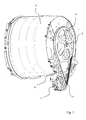
- Fig. 1 shows by way of example the motor 1 in an insert in a washing machine, which is attached to the tub 2 and is provided for driving the drum.
- a motor 1 here is a brush-less synchronous motor with permanent magnet rotor 10 is provided, which is supplied with a frequency converter (not shown).
- a frequency converter (not shown).
- the rotational movement is transmitted to the pulley 4 of the drum shaft 5.
- An engine 1 of this type is also suitable for other drives, such as pumps, blowers in electrical appliances, in particular household appliances, such as washing machines, dryers, dishwashers, cooker hoods or vacuum cleaners.
- Such an engine 1 is particularly for operation at very high speeds, for example in the range of 20,000 to 50,000 rpm to run. These speeds are suitable for vacuum cleaner fans or rotary actuators in washing machines. Also for speeds in the range of 3,000 to 5,000 rpm, such as they are needed for driving a clothes dryer, an engine of the type mentioned is suitable.
- Fig. 2 shows by way of example the rotor in detail in an exploded view.
- the base body 12 is rotatably connected to the shaft 11 in order to transmit the torque introduced via the magnets 13 to the shaft 11.
- the main body 12 expediently comprises a laminated core or is formed from such.
- the base body 12 is provided with shell-side open grooves or grooves 14, in which the magnets 13 are inserted.
- the magnets 13 are formed partially circular in order to follow the at least substantially the cylindrical shape of the rotor 10 or to allow a cylindrical shape as possible without major offsets.
- segment magnets are preferably used in the embodiment as a ferrite magnet.
- Other magnets, such as rare earth magnets can also be used, depending on the requirements for the engine 1.
- the cage 15 which is based on a cylindrical shape and at its end faces 10a (FIG. Figure 3 ) each comprise a circumferential ring 16a, 16b, which are fixedly connected to each other by means of struts 17, preferably made in one piece.
- the struts 17 lie in intermediate spaces 19 (FIG. Fig. 4 ) between the side surfaces 13a of the magnets 13 and the side surfaces 14a of the grooves 14.
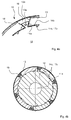
- Fig. 3 shows the rotor 10 in the assembled state, here without shaft 11, which can be pushed and fixed by the opening 11a in the base body 12 under a press fit.
- the struts 17 extend in the direction of the second ring 16b on the opposite end face.
- the struts 17 surround or embed the magnets 12 at the edge, so that the outside surfaces 13b of the magnets 13 are exposed.
- Fig. 4a shows for a preferred embodiment in detail the connection of a magnet 13 on a side surface 14a of the groove 14, which is bounded in the circumferential direction by two adjacent projections 12a.
- the side surface 14a is inclined inwards, ie to the shell-side opening or free surface for the magnet 13, inclined.
- the side surface 13a of the magnet 13 comes to rest, so that a detachment of the magnets 13 is prevented at high centrifugal forces.
- the remaining gap 19 between the material of the base body 12 and the magnet 13 is filled with plastic material to form the struts 17.
- the struts 17 are in this case in cross section at least approximately trapezoidal or curved trapezoidal in shape, with the long side of the trapezoid on the outer surface 10 b ( Fig. 3 ) is located.
- groove bottom 14b is a groove 14c, which is also filled with plastic to form an additional, the rings 16a, 16b connecting strut 17b. Further, the magnets are moved or held by the pressure built up in the groove bottom 14b during the introduction of the plastic mass to the outside in the predetermined position.
- Fig. 4b shows in a frontal view of the stocked with magnets 13 main body 12 in a schematic view.
- two grooves 14c are provided for the formation of the inside struts 17c, in order to improve the overall stability of the cage 15 and to achieve a uniform force distribution.
- gaps or gaps between the inclined side surface 14a and the side surface 13a of the magnet 13 may be filled with plastic compound to compensate for dimensional accuracy of the individual components and improve the overall strength of the rotor 10.
- Fig. 5 shows an embodiment of the rotor 10 with a slipped sleeve 18, the coat side, the magnets 13 and the cage 15, at least the struts 17 covers.
- the sleeve is formed slightly smaller in diameter than the stocked with the magnets 13 and cage body 15 12 to provide a good and lasting tight fit under a press fit.
- the sleeve 18 comprises two shell bodies 18a, 18b or is formed from these.
- the shell bodies 18a, 18b each have on one end face a circumferential edge projection 18c, which serves as a stop or fixation for the parts 13, 15 applied to the shaped body and secures them against axial slippage.
- the bushing design 18 is particularly suitable for high speed engines, for example in the range of 20,000 to 50,000 rpm nominal speed.
- the attachment of the permanent magnets 13 to the base body 12 by means of the cage 15 as described above is particularly suitable for internal rotor as shown in the figures, but can be used in the same way for external rotor.
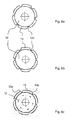
- Fig. 6a to 6c show in the frontal sectional view various shapes of the magnets 13 and the base body 12 with the corresponding projections 12 for the lateral abutment and the positioning of the magnets 13 on the base body 12th
- Fig. 6c shows an embodiment in which the magnets are sharply chamfered at their side surfaces 13 a, to provide space for a strut 17 with a wedge-shaped and large cross-section.
Landscapes
- Engineering & Computer Science (AREA)
- Power Engineering (AREA)
- Manufacturing & Machinery (AREA)
- Permanent Field Magnets Of Synchronous Machinery (AREA)
- Manufacture Of Motors, Generators (AREA)
Abstract
Die Erfindung betrifft einen Rotor (10) für einen Elektromotor (1), aufweisend eine zylindrische Form mit einem an einer Welle (11) montierten Grundkörper (12), in dem zumindest mehrere umlaufend angeordnete Nuten (14) bzw. Mulden ausgebildet sind, in die jeweils ein Permanentmagnet (13) eingesetzt und fixiert ist. Der Rotor zeichnet sich dadurch aus, dass sich bei eingesetzten Permanentmagneten (13) zwischen in den Nuten (14) bzw. Mulden ein Hohlraum ausbildet, und dass der Grundkörper (12) mit den darin eingesetzten Permanentmagneten (13) in einer Kunststoffmasse derart eingebunden ist, dass sich ein Käfig (15) mit an den Stirnseiten ausgebildeten umlaufenden Ringen (16a, 16b), die mit in den Hohlräumen (19) ausgebildeten Längsstreben (17) miteinander verbunden sind, ergibt. Die Erfindung betrifft ferner einen elektrisch antreibbaren Synchronmotor mit einem entsprechenden Rotor (10). Die Erfindung betrifft auch ein Verfahren zur Herstellung eines entsprechenden Rotors (10), bei dem der Käfig (15) im Spritzgussverfahren erzeugt wird.The invention relates to a rotor (10) for an electric motor (1), having a cylindrical shape with a base body (12) mounted on a shaft (11) in which at least a plurality of peripherally arranged grooves (14) or hollows are formed each one permanent magnet (13) is inserted and fixed. The rotor is distinguished by the fact that a cavity forms in the grooves (14) or depressions when the permanent magnets (13) are inserted, and that the base body (12) with the permanent magnets (13) inserted therein is incorporated in a plastics material in such a way in that a cage (15) is provided with peripheral rings (16a, 16b) formed on the end faces and connected to longitudinal struts (17) formed in the cavities (19). The invention further relates to an electrically driven synchronous motor with a corresponding rotor (10). The invention also relates to a method for producing a corresponding rotor (10), in which the cage (15) is produced by injection molding.
Description
Die Erfindung betrifft einen Rotor für einen Elektromotor, aufweisend eine zylindrische Form mit einem an einer Welle montierten Grundkörper, in dem zumindest mehrere umlaufend angeordnete Nuten bzw. Mulden ausgebildet sind, in die jeweils ein Permanentmagnet eingesetzt und fixiert ist.The invention relates to a rotor for an electric motor, comprising a cylindrical shape with a base body mounted on a shaft, in which at least a plurality of circumferentially arranged grooves or troughs are formed, in each of which a permanent magnet is inserted and fixed.
Bei bekannten Rotoren werden die Magnete gewöhnlich an einer Außenseite des Rotors oder in Taschen desselben verklebt, um eine dauerhafte Verbindung zwischen dem Rotor und den Permanentmagneten bereitzustellen. Wichtig ist, die Magnete in eine definierte Position zu bringen, um auftretende Unwuchten während des Betriebes zu minimieren. Die Magnete sollen zudem gegen mechanische Beschädigungen geschützt sein. Dazu ist beispielsweise bekannt, die Magnete mit einem Kunststoff zu umspritzen.In known rotors, the magnets are usually bonded to an outside of the rotor or in pockets thereof to provide a permanent connection between the rotor and the permanent magnets. It is important to bring the magnets into a defined position in order to minimize occurring imbalances during operation. The magnets should also be protected against mechanical damage. For example, it is known to overmold the magnets with a plastic.
Aus der
Diese recht stabile Ausführung ist jedoch recht aufwändig herzustellen, da mehrere verschiedene Montageschritte zur sicheren Fixierung der Magnete notwendig sind. Ferner muss stets berücksichtigt werden, dass der Materialmix aus Kleber, Magnetmaterial und Kunststoff bei mechanischer und thermischer Beanspruchung keine negativen Eigenschaften aufweist bzw. bekommt.However, this fairly stable design is quite complicated to produce, since several different assembly steps for secure fixation of the magnets are necessary. Furthermore, it must always be taken into account that the material mix of adhesive, magnetic material and plastic has no negative properties under mechanical and thermal stress.
Der Erfindung liegt somit die Aufgabe zu Grunde, einen einfach aufgebauten Rotor für einen Elektromotor bereitzustellen, der hohen Belastungen, insbesondere hohe Drehzahlen und thermische Belastungen sicher standhält.The invention is therefore based on the object to provide a simply constructed rotor for an electric motor, the high loads, especially high speeds and thermal loads safely withstand.
Erfindungsgemäß wird unter anderem diese Aufgabe durch einen Rotor mit den Merkmalen des unabhängigen Anspruchs 1, einen Motor gemäß Anspruch 12 und durch ein Verfahren gemäß Anspruch 13 gelöst. Vorteilhafte Ausgestaltungen und Weiterbildungen der Erfindung ergeben sich aus den abhängigen Ansprüchen.According to the invention, inter alia, this object is achieved by a rotor having the features of
Die mit der Erfindung erreichbaren Vorteile bestehen darin, dass durch die Ausbildung eines in sich stabilen Käfigs auf weitere Befestigungsmittel, wie Kleber, verzichtet werden kann. Ferner ist an den sensiblen Übergangstellen zwischen Magnet und Grundkörper kein unbeherrschbarer Materialmix mehr vorhanden, da der sichere Halt durch die formschlüssige Einbindung des Käfigs in oder an die Einzelteile des Rotors bereitgestellt wird. Der Rotor zeichnet sich somit dadurch aus, dass sich bei eingesetzten Permanentmagneten zwischen den Nuten bzw. Mulden ein Hohlraum ausbildet, und dass der Grundkörper mit den darin eingesetzten Permanentmagneten in einer Kunststoffmasse derart eingebunden ist, dass sich ein Käfig aus Kunststoffmaterial mit an den Stirnseiten ausgebildeten umlaufenden Ringen, die mit in den Hohlräumen ausgebildeten Längsstreben miteinander verbunden sind, ergibt. Neben der formschlüssigen Einbindung hat die Ausbildung eines Käfigs mit miteinander verbundenen Streben den Vorteil, dass der Käfig selbst dazu ausgebildet ist, die Magnete unter ständiger Krafteinwirkung oder Druckbelastung radial gegen den Grundkörper, oder genauer ausgedrückt gegen den Nutgrund der Nuten oder Einbuchtungen zu pressen und so auf dem Formkörper sicher zu fixieren. Die Ausbildung des Kunststoffkäfigs zur Fixierung der Magnete ist besonders gut geeignet für Ferritmagnete, da diese durch die Kunststoffummantelung, die der Käfig bietet, in sich stabilisiert und Abplatzer vom mürben Ferritmagneten verhindert werden.The achievable with the invention advantages are that can be dispensed with by the formation of a stable cage in itself on further fastening means, such as adhesive. Furthermore, no unmanageable material mix is more present at the sensitive transition points between the magnet and the base body, since the secure hold is provided by the positive engagement of the cage in or on the individual parts of the rotor. The rotor is thus distinguished by the fact that a cavity is formed between the grooves or hollows when permanent magnets are used, and that the base body with the permanent magnets inserted therein is bound in a plastic mass in such a way that a cage of plastic material is formed on the end faces circumferential rings, which are connected to each other with formed in the cavities longitudinal struts results. In addition to the form-fitting involvement of the formation of a cage with interconnected struts has the advantage that the cage itself is designed to press the magnets under constant force or pressure load radially against the body, or more precisely against the groove bottom of the grooves or indentations and so to securely fix on the molding. The formation of the plastic cage for fixing the magnets is particularly well suited for ferrite magnets, since these are stabilized by the plastic sheath, which offers the cage, in itself and chipping the friable ferrite magnets are prevented.
Um noch sicherer zu verhindern, dass die Magnete aufgrund auftretender Zentrifugalkräfte sich radial nach außen bewegen oder vom Formkörper ablösen ist es vorgesehen, dass die Längsstreben im Profil eine Dreiecks- oder Trapezform mit außenliegender Längsseite aufweisen.To prevent even more sure that the magnets move due to centrifugal forces occurring radially outward or detach from the molding body, it is provided that the longitudinal struts in profile have a triangular or trapezoidal shape with external longitudinal side.
In einer vorteilhaften Weiterbildung ist der Kunststoff ein mit Fasern, beispielsweise Glas-Polyester- Keflar- oder Karbonfaser verstärkter Kunstsoff. Damit wird eine in sich stabile Ausbildung bzw. stabiler Gesamtverbund des Käfigs erreicht. Dabei ist es vorteilhaft, wenn die Fasern in Längsrichtung der Streben ausgerichtet sind.In an advantageous development of the plastic is reinforced with fibers, such as glass-polyester Keflar- or carbon fiber Kunstsoff. This achieves a stable formation or stable overall composite of the cage. It is advantageous if the fibers are aligned in the longitudinal direction of the struts.
In einer zweckmäßigen Ausführung ist der Käfig im Spritzgießverfahren hergestellt, wodurch eine rationelle Großserienfertigung ermöglicht wird.In an expedient embodiment, the cage is produced by injection molding, whereby a rational mass production is made possible.
In einer anderen Ausführung ist der Käfig als Kunststoffformkörper vorgefertigt auf den Grundkörper und die Magnete aufgebracht bzw. übergestülpt. Damit entfällt bei der Montage der Spritzgießprozess, der für manche Anwendungen oder kleinere Stückzahlen nicht lohnend bereitgestellt werden kann.In another embodiment, the cage is prefabricated as a plastic molded body applied to the base body and the magnets or slipped over. This eliminates the need for assembly during the injection molding process, which can not be provided for some applications or smaller quantities not worthwhile.
Der Käfig kann dabei einsatzbedingt ohne aufwändige Maßnahmen so ausgebildet werden, dass die Magnetflächen außenseitig freiliegend ausgebildet sind, beispielsweise für trocken laufende Antriebe oder dass die Magnetflächen außenseitig von Kunstsoff verdeckt sind, um beispielsweise eine vollständige wasserdichte Kapselung bereitzustellen. Ferner werden Beschädigungen der Magnete bei Berührung des Rotors vermieden.The cage can be used in this case without elaborate measures are designed so that the magnetic surfaces are exposed on the outside, for example for dry running drives or that the magnetic surfaces are covered on the outside of Kunstsoff, for example, to provide a complete waterproof enclosure. Furthermore, damage to the magnets when touching the rotor can be avoided.
In einer insgesamt zweckmäßigen Ausführung weisen die im Grundkörper eingebrachten Nuten schräge, nach innen geneigte Seitenflächen auf, an denen die Seitenflächen der Magnete, die eine im wesentlichen gleiche Neigung der Seitenflächen aufweisen, zumindest mittelbar zur Anlage kommen. Sind die Nuten im Querschnitt keilförmig oder trapezförmig ausgebildet, in denen die korrespondierende Keilform der Magnete zur Anlage kommen kann, wodurch das Ablösen bei auftretenden Zentrifugalkräften sicher verhindert wird. Durch den hier bereitgestellten Hinterschnitt wird zusätzlich die Montage verbessert bzw. vereinfacht.In an overall expedient embodiment, the grooves introduced in the base body have oblique, inwardly inclined side surfaces on which the side surfaces of the magnets, which have a substantially equal inclination of the side surfaces, at least indirectly come to rest. Are the grooves in cross-section wedge-shaped or trapezoidal in which the corresponding wedge shape of the magnets can come to rest, whereby the separation is reliably prevented when occurring centrifugal forces. Due to the undercut provided here, the assembly is additionally improved or simplified.
Zur Bereitstellung von Verbindungsstegen mit vordefinierter Mindestdicke ist es in einer insgesamt vorteilhaften Ausführung vorgesehen, die Nuten im Grundkörper jeweils in ihrem Nutgrund zumindest mit einer durchgehenden Rinne zu versehen, die durchgehend mit Kunststoff ausgefüllt sind und somit als Streben zur Verbindung mit den beiden stirnseitigen Ringen fungieren. Ferner wird das Ausfüllen von Hohlräumen zwischen Nutgrund oder Muldengrund und der innenseitigen Magnetfläche bewirkt. Insgesamt wird die Stabilität des Käfigs verbessert und ein stabiler Verbund aus Formkörper, Käfig und Magnete erreicht. Ferner kann auf einfache Weise der vorgegebene Außendurchmesser des Rotors durch die Positionierung der Magnete eingestellt werden, wobei die durch die Ausfüllung der dadurch entstehenden Hohlräume am Nutgrund der Toleranzausgleich realisiert wird.To provide connecting webs with a predefined minimum thickness, it is provided in an overall advantageous embodiment to provide the grooves in the base body in each case in their groove bottom at least with a continuous channel, which are continuously filled with plastic and thus act as struts for connection to the two end-face rings , Furthermore, the filling of cavities between the groove bottom or trough bottom and the inside magnetic surface is effected. Overall, the stability of the cage is improved and achieved a stable composite of moldings, cage and magnets. Further, the predetermined outer diameter of the rotor can be adjusted by the positioning of the magnets in a simple manner, wherein the filling of the resulting cavities at the groove bottom of the tolerance compensation is realized.
Zu weiteren Verbesserung des sicheren Halts der Magnete auf dem Formkörper ist eine Hülse oder ein Rohr vorgesehen, die/das außenseitig über die im Käfig eingebetteten Magnete gestülpt bzw. gepresst ist.To further improve the secure hold of the magnets on the molded body, a sleeve or a tube is provided, which is slipped or pressed on the outside via the magnets embedded in the cage.
In einer vorteilhaften Weiterbildung umfasst die Hülse zwei Schalen oder Rohrabschnitte, die jeweils einen stirnseitigen, umlaufenden Randansatz zur Fixierung am Grundkörper oder Ring aufweisen. Der kragenartige Randansatz steigert noch einmal die Stabilität und hält die Hülse selbst in die vorgegebene Position. Die Hülse ist dabei beispielsweise als Tiefziehteil aus einer Kunststoffplatte oder Blech oder einem Spritzgießteil aus Kunststoff hergestellt.In an advantageous embodiment, the sleeve comprises two shells or pipe sections, each having a frontal, circumferential edge approach for fixing to the main body or ring. The collar-like edge approach increases stability once again and keeps the sleeve itself in the specified position. The sleeve is made for example as a deep-drawn part of a plastic plate or sheet or an injection molded plastic.
Die Erfindung betrifft ferner einen bürstenlosen, elektrisch antreibbaren Synchronmotor mit einem Rotor, wie vorstehend beschrieben.The invention further relates to a brushless, electrically driven synchronous motor with a rotor, as described above.
Die Erfindung betrifft ferner ein Verfahren zum Herstellung eines Rotors (10) wie vorstehend beschrieben, umfassend folgende Schritte
- Einlegen des Grundkörpers in eine in einer Spritzgießform befindlichen Vorrichtung,
- Einlegen bzw.- Positionieren von Permanentmagneten in die im Grundkörper befindlichen Mulden oder Nuten,
- Zweckmäßigerweise Schließen der Spritzgießform mittels eines Verschlussteils, oder die Spritzgießform anderweitig in Bereitschaft versetzten,
- Einspritzen einer fließfähigen, aushärtbaren Kunststoffmasse, wobei das Einspritzen mit Hilfe eines Druckes erfolgt, der eine Ausbreitung der Kunststoffmasse in Hohlräume zwischen den Magneten und den Mulden oder Nuten im Hohlkörper verursacht und sich ein Käfig mit an den Stirnseiten ausgebildeten umlaufenden Ringen, die mit in den Hohlräumen ausgebildeten Längsstreben miteinander verbunden sind, ausbildet. Damit lässt sich auf einfache Weise in einer einzigen Fertigungsstation sowohl das Ausgießen der Hohlräume als auch die Fixierung der Magnete im Rotor bewerkstelligen. Eine zusätzliche Klebung der Magnete an dem Grundkörper kann entfallen. Der Fixierung der Magnete erfolgt somit kleberlos.
- Inserting the main body into a device located in an injection mold,
- Inserting or positioning permanent magnets in the recesses or grooves in the base body,
- Conveniently closing the injection mold by means of a closure part, or otherwise put the injection mold in standby,
- Injecting a flowable, hardenable plastic mass, wherein the injection with Helping a pressure takes place, which causes a spread of the plastic material in cavities between the magnets and the troughs or grooves in the hollow body and a cage with trained on the end faces circumferential rings, which are connected to each other in the cavities formed longitudinal struts, forms. This can be done easily in a single manufacturing station both the pouring of the cavities and the fixation of the magnets in the rotor. An additional adhesion of the magnets to the body can be omitted. The fixation of the magnets thus takes place without glue.
In einer vorteilhaften Weiterbildung wird vor dem Einspritzen der fließfähigen, aushärtbaren Kunststoffmasse eine Hülse über die auf dem Grundkörper eingelegten bzw. positionierten Magnete gestülpt, wobei die Hülse ein Herausfließen der Kunststoffmasse größtenteils verhindert, sodass die Spritzgießform oder das Spritzgießwerkzeug, das die Form und die Vorrichtungen zur Positionierung des Grundkörpers und der Magneten umfasst, stark vereinfacht werden kann. Die Positionierung der Magnete wird hierbei bereits durch die Hülse bereitgestellt.In an advantageous development, a sleeve is placed over the magnets inserted or positioned on the main body prior to the injection of the flowable, curable plastic material, wherein the sleeve largely prevents the plastic mass from flowing out, so that the injection mold or the injection mold, the mold and the devices for positioning the base body and the magnets comprises, can be greatly simplified. The positioning of the magnets is already provided by the sleeve.
Ein Ausführungsbeispiel der Erfindung ist in den Zeichnungen rein schematisch dargestellt und wird nachfolgend näher beschrieben. Es zeigen
- Fig. 1:
- einen elektrischen Motor in Wirkposition in einer Waschmaschine
- Fig. 2:
- den Rotor in einer Explosionsdarstellung
- Fig. 3:
- den Rotor des Elektromotors in einer perspektivischen Ansicht
- Fig. 4a, 4b:
- die Verbindung zwischen Magnet und Grundkörper in einer Detailansicht
- Fig. 5:
- eine Ausführung des Rotors mit übergestülpter Hülse und
- Fig. 6a - c:
- Verschiede Ausführungen des Rotors in einer stirnseitigen Schnittansicht.
- Fig. 1:
- an electric motor in operative position in a washing machine
- Fig. 2:
- the rotor in an exploded view
- 3:
- the rotor of the electric motor in a perspective view
- 4a, 4b:
- the connection between the magnet and the main body in a detailed view
- Fig. 5:
- an embodiment of the rotor with slipped sleeve and
- Fig. 6a - c:
- Various embodiments of the rotor in a frontal sectional view.
Ein Motor 1 dieser Bauart ist auch für andere Antriebe, wie Pumpen, Gebläse in elektrischen Geräten, insbesondere Haushaltsgeräten, wie Waschmaschinen, Trockner, Geschirrspüler, Dunstabzugshauben oder Staubsauger, geeignet. Ein solcher Motor 1 ist besonders für den Betrieb mit sehr hohen Drehzahlen, beispielsweise im Bereich von 20 000 bis 50 000 u/min, zu laufen. Diese Drehzahlen sind für Staubsaugergebläse oder Drehantrieben in Waschmaschinen geeignet. Auch für Drehzahlen im Bereich von 3 000 bis 5000 u/min, wie sie für den Antrieb eines Wäschetrockners benötigt werden, ist ein Motor der genannten Bauart geeignet.An
Ferner können in einer weiteren Ausführung des Rotors 10 Spalte oder Lücken zwischen der schrägen Seitenfläche 14a und der Seitenfläche 13a des Magneten 13 mit Kunststoffmasse ausgefüllt werden, um Toleranzen hinsichtlich der Maßhaltigkeit der einzelnen Bauteile auszugleichen und die Gesamtfestigkeit des Rotors 10 zu verbessern.Further, in another embodiment of the
Die Befestigung der Permanentmagnete 13 an den Grundkörper 12 mit Hilfe des Käfigs 15, wie oben beschrieben, ist besonders geeignet für Innenläufer, wie in den Figuren gezeigt, kann jedoch in gleicher Weise für Außenläufer verwendet werden.The attachment of the
Claims (15)
dadurch gekennzeichnet,
dass sich bei eingesetzten Permanentmagneten (13) zwischen in den Nuten (14) bzw. Mulden ein Hohlraum ausbildet, und dass der Grundkörper (12) mit den darin eingesetzten Permanentmagneten (13) in einer Kunststoffmasse derart eingebunden ist, dass sich ein Käfig (15) mit an den Stirnseiten ausgebildeten umlaufenden Ringen (16a, 16b), die mit in den Hohlräumen (19) ausgebildeten Längsstreben (17) miteinander verbunden sind, ergibt.Rotor (10) for an electric motor (1), having a cylindrical shape with a shaft (11) mounted on the base body (12) in which at least a plurality of circumferentially arranged grooves (14) or troughs are formed, in each of which a permanent magnet (13) is inserted and fixed,
characterized,
that when inserted permanent magnets (13) between the grooves (14) or recesses, a cavity forms, and that the base body (12) with inserted therein permanent magnets (13) in a plastics material incorporated such that a cage (15 ) with formed at the end faces circumferential rings (16a, 16b), which are connected to each other in the cavities (19) formed longitudinal struts (17) together.
dadurch gekennzeichnet,
dass die Längsstreben (17) im Profil eine Dreiecks- oder Trapezform mit außenliegender Längsseite aufweisen.Rotor (10) according to claim 1,
characterized,
in that the longitudinal struts (17) in the profile have a triangular or trapezoidal shape with an outer longitudinal side.
dadurch gekennzeichnet,
dass der Kunststoff ein mit Fasern, beispielsweise Polyester-, Keflar- oder Karbonfaser verstärkter Kunstsoff ist.Rotor (10) according to claim 1 or 2,
characterized,
that the plastic material is a reinforced with fibers, such as polyester, carbon fiber or Keflar- Kunstsoff.
dadurch gekennzeichnet,
dass der Käfig (15) im Spritzgießverfahren hergestellt istRotor (10) according to one of claims 1 to 3,
characterized,
that the cage (15) is made by injection molding
dadurch gekennzeichnet,
dass der Käfig (15) als Kunststoffformkörper vorgefertigt auf den Grundkörper (12) und die Magnete (13) aufgebracht ist.Rotor (10) according to one of claims 1 to 3,
characterized,
that the cage (15) as a preformed plastic molded body is applied to the base body (12) and the magnets (13).
dadurch gekennzeichnet,
dass die Magnetflächen (13b) außenseitig freiliegend ausgebildet sind.Rotor (10) according to one of claims 1 to 5,
characterized,
that the magnetic areas (13b) are formed externally exposed.
dadurch gekennzeichnet,
dass die Magnetflächen (13b) außenseitig von Kunststoff verdeckt sind.Rotor (10) according to one of claims 1 to 5,
characterized,
that the magnetic surfaces (13b) are covered on the outside by plastic.
dadurch gekennzeichnet,
dass die im Grundkörper (12) eingebrachten Nuten (14) schräge, nach innen geneigte Seitenflächen (14a) aufweisen, an denen die Seitenflächen (13a) der Magnete (13), die eine im wesentlichen gleiche Neigung der Seitenflächen (14a) aufweisen, mittelbar oder direkt zur Anlage kommen.Rotor (10) according to one of claims 1 to 7,
characterized,
in that the grooves (14) introduced in the base body (12) have oblique, inwardly inclined side surfaces (14a) on which the side surfaces (13a) of the magnets (13), which have a substantially equal inclination of the side surfaces (14a), indirectly or come directly to the plant.
dadurch gekennzeichnet,
dass die Nuten (14) oder Mulden im Grundkörper (12) jeweils in ihrem Nutgrund (14b) oder Muldengrund zumindest eine durchgehende Rinne (14c) aufweisen, die durchgehend mit Kunststoff ausgefüllt sind und somit als Streben (17b) zur Verbindung mit den beiden stirnseitigen Ringen (16a, 16b) fungieren und/oder das Ausfüllen von Hohlräumen zwischen Nutgrund (14b) oder Muldengrund und der innenseitigen Magnetfläche bewirkt.Rotor (10) according to one of claims 1 to 8,
characterized,
in that the grooves (14) or hollows in the base body (12) each have at least one continuous channel (14c) in their groove base (14b) or recess bottom, which are continuously filled with plastic and thus as struts (17b) for connection to the two end faces Wrestling (16a, 16b) act and / or filling of cavities between groove bottom (14b) or trough base and the inside magnetic surface causes.
gekennzeichnet durch
eine Hülse (18) oder Rohr, das außenseitig über die im Käfig (15) eingebetteten Magnete (13) gestülpt ist.Rotor (10) according to one of claims 1 to 9,
marked by
a sleeve (18) or tube which is slipped on the outside over the magnets (13) embedded in the cage (15).
dadurch gekennzeichnet,
dass Hülse (18) zwei Schalen (18a, 18b) oder Rohrabschnitte umfasst, die jeweils einen stirnseitigen, umlaufenden Randansatz (18c) zur Fixierung am Grundkörper (12) oder Ring (16a, 16b) des Käfigs (15) aufweisen.Rotor (10) according to claim 10,
characterized,
in that the sleeve (18) comprises two shells (18a, 18b) or pipe sections, each of which has an end-side peripheral edge attachment (18c) for fixing to the base body (12) or ring (16a, 16b) of the cage (15).
dadurch gekennzeichnet,
dass vor dem Einspritzen der fließfähigen, aushärtbaren Kunststoffmasse eine Hülse (18) über die auf dem Grundkörper (12) eingelegten bzw. positionierten Magnete (14) gestülpt wird.Method according to claim 13,
characterized,
that prior to injecting the flowable, hardenable plastics material a sleeve (18) on the on the base body (12) inserted or positioned magnets (14) is placed.
dadurch gekennzeichnet,
dass die Permanentmagneten (13) an der Oberfläche des Grundkörpers (12) oder an der Innenfläche der Spritzgussform anliegen, bevor die aushärtbare Kunststoffmasse in die Spritzgussform eingespritzt wird.Method according to claim 13,
characterized,
in that the permanent magnets (13) bear against the surface of the main body (12) or against the inner surface of the injection mold before the hardenable plastic mass is injected into the injection mold.
Priority Applications (1)
| Application Number | Priority Date | Filing Date | Title |
|---|---|---|---|
| PL14169382T PL2840679T3 (en) | 2013-07-16 | 2014-05-22 | Rotor for an electric motor and method for manufacturing a rotor for an electric motor |
Applications Claiming Priority (1)
| Application Number | Priority Date | Filing Date | Title |
|---|---|---|---|
| DE102013107526.6A DE102013107526A1 (en) | 2013-07-16 | 2013-07-16 | Rotor for an electric motor and method of manufacturing a rotor |
Publications (3)
| Publication Number | Publication Date |
|---|---|
| EP2840679A2 true EP2840679A2 (en) | 2015-02-25 |
| EP2840679A3 EP2840679A3 (en) | 2015-12-09 |
| EP2840679B1 EP2840679B1 (en) | 2017-03-08 |
Family
ID=50774656
Family Applications (1)
| Application Number | Title | Priority Date | Filing Date |
|---|---|---|---|
| EP14169382.0A Active EP2840679B1 (en) | 2013-07-16 | 2014-05-22 | Rotor for an electric motor and method for manufacturing a rotor for an electric motor |
Country Status (4)
| Country | Link |
|---|---|
| EP (1) | EP2840679B1 (en) |
| DE (1) | DE102013107526A1 (en) |
| ES (1) | ES2623809T3 (en) |
| PL (1) | PL2840679T3 (en) |
Cited By (2)
| Publication number | Priority date | Publication date | Assignee | Title |
|---|---|---|---|---|
| DE102016112719A1 (en) | 2016-07-12 | 2018-01-18 | Miele & Cie. Kg | Rotor, permanent magnet synchronous electric motor and household appliance |
| CN114094780A (en) * | 2021-12-02 | 2022-02-25 | 安徽智鸥驱动科技有限公司 | Mounting fixture and mounting method for permanent magnet of outer rotor brushless motor |
Families Citing this family (3)
| Publication number | Priority date | Publication date | Assignee | Title |
|---|---|---|---|---|
| DE102019201056A1 (en) | 2019-01-29 | 2020-07-30 | Rolls-Royce Deutschland Ltd & Co Kg | Rotor with a drum arrangement for an electrical machine |
| DE102020105472A1 (en) * | 2020-03-02 | 2021-09-02 | Dr. Ing. H.C. F. Porsche Aktiengesellschaft | Method for manufacturing a rotor of an electrical machine |
| DE102020209212A1 (en) | 2020-07-22 | 2022-01-27 | Vitesco Technologies GmbH | Arrangement of individual magnet holders on a rotor or stator, electric motor, rotor, stator and joining process |
Citations (1)
| Publication number | Priority date | Publication date | Assignee | Title |
|---|---|---|---|---|
| DE3719197A1 (en) | 1987-06-09 | 1989-01-05 | Thyssen Edelstahlwerke Ag | Rotor for electrical machines |
Family Cites Families (6)
| Publication number | Priority date | Publication date | Assignee | Title |
|---|---|---|---|---|
| DE2845702C2 (en) * | 1978-10-20 | 1983-01-20 | Nsm-Apparatebau Gmbh Kg, 6530 Bingen | Method for manufacturing a rotor for a small electric motor |
| DE102004054277A1 (en) * | 2004-11-10 | 2006-05-24 | Minebea Co., Ltd. | Rotor assembly for an electric machine and method of manufacturing a rotor assembly |
| DE502005010177D1 (en) * | 2005-07-29 | 2010-10-14 | Siemens Ag | Permanent magnet rotor for a brushless electric machine |
| DE102006036392A1 (en) * | 2006-03-31 | 2007-11-22 | Aweco Appliance Systems Gmbh & Co. Kg | Electric motor with rotor, rotor and method for producing a rotor for an electric motor |
| DE102009060438A1 (en) * | 2009-12-22 | 2011-06-30 | KSB Aktiengesellschaft, 67227 | Rotor with short-circuit cage |
| JP5842365B2 (en) * | 2011-04-02 | 2016-01-13 | 日本電産株式会社 | Rotor unit, rotating electric machine, and method of manufacturing rotor unit |
-
2013
- 2013-07-16 DE DE102013107526.6A patent/DE102013107526A1/en not_active Withdrawn
-
2014
- 2014-05-22 PL PL14169382T patent/PL2840679T3/en unknown
- 2014-05-22 ES ES14169382.0T patent/ES2623809T3/en active Active
- 2014-05-22 EP EP14169382.0A patent/EP2840679B1/en active Active
Patent Citations (1)
| Publication number | Priority date | Publication date | Assignee | Title |
|---|---|---|---|---|
| DE3719197A1 (en) | 1987-06-09 | 1989-01-05 | Thyssen Edelstahlwerke Ag | Rotor for electrical machines |
Cited By (2)
| Publication number | Priority date | Publication date | Assignee | Title |
|---|---|---|---|---|
| DE102016112719A1 (en) | 2016-07-12 | 2018-01-18 | Miele & Cie. Kg | Rotor, permanent magnet synchronous electric motor and household appliance |
| CN114094780A (en) * | 2021-12-02 | 2022-02-25 | 安徽智鸥驱动科技有限公司 | Mounting fixture and mounting method for permanent magnet of outer rotor brushless motor |
Also Published As
| Publication number | Publication date |
|---|---|
| PL2840679T3 (en) | 2017-08-31 |
| EP2840679B1 (en) | 2017-03-08 |
| ES2623809T3 (en) | 2017-07-12 |
| EP2840679A3 (en) | 2015-12-09 |
| DE102013107526A1 (en) | 2015-01-22 |
Similar Documents
| Publication | Publication Date | Title |
|---|---|---|
| EP2840679B1 (en) | Rotor for an electric motor and method for manufacturing a rotor for an electric motor | |
| EP1748533B1 (en) | Rotor with permanent magnets for a brushless electric machine | |
| EP2040354B2 (en) | Rotor can of a drive motor for a pump assembly | |
| EP2502331B1 (en) | Rotor for an electrical motor | |
| DE69403589T2 (en) | ROTOR ASSEMBLY AND METHOD FOR THE PRODUCTION THEREOF | |
| EP1722459B1 (en) | Electric machine supporting the rotor on the frontside of the stator | |
| DE102015203018A1 (en) | Electric machine with magnet attached by means of plastic | |
| DE102006036392A1 (en) | Electric motor with rotor, rotor and method for producing a rotor for an electric motor | |
| DE102017003800B4 (en) | ROTATING ELECTRICAL MACHINE WITH A ROTOR INCLUDING A SUPPORTING ELEMENT | |
| DE102007000213A1 (en) | Permanent magnet motor | |
| EP3610557B1 (en) | Electrical drive motor, wet rotor pump, and domestic appliance, and method for producing an electric drive motor of this kind | |
| DE4442869A1 (en) | Runner for an electrical machine | |
| WO2011066815A2 (en) | Electric motor and method for producing a stator | |
| EP2744079A2 (en) | Rotor and electric motor | |
| EP2602497A1 (en) | Connection between two components and method for connecting two components | |
| DE102014226047A1 (en) | Spoke rotor with encapsulation | |
| DE102007047715A1 (en) | Rotor, for an electric machine as well as electrical machine | |
| DE102005033561A1 (en) | Support ring for rotary electrical machine, has permanent magnets, each inserted into holder in form-fit manner, where each holder comprises two retaining sections for fixing holder in respective slot and for holding respective magnet | |
| EP2945260A2 (en) | Electrical motor of a hand-hold tool | |
| DE1488502B2 (en) | FASTENING AND INSULATION OF A ROTATING BODY ON ITS SHAFT | |
| DE10250261A1 (en) | Commutator for an electrical machine and method for its production | |
| DE4111411A1 (en) | High speed electric motor rotor with protective cover and contg. breakable components - has cover formed as screw spring of draw type with windings in untensioned state locating against each other or spaced apart | |
| EP1209799B1 (en) | Rotor of an electric machine and method for manufacturing the same | |
| EP3352338A1 (en) | Method for fixing a magnetic element in a recess of a rotor or a stator of an electric machine and electric machine | |
| EP3364529A1 (en) | Stator for an electric motor |
Legal Events
| Date | Code | Title | Description |
|---|---|---|---|
| PUAI | Public reference made under article 153(3) epc to a published international application that has entered the european phase |
Free format text: ORIGINAL CODE: 0009012 |
|
| 17P | Request for examination filed |
Effective date: 20140522 |
|
| AK | Designated contracting states |
Kind code of ref document: A2 Designated state(s): AL AT BE BG CH CY CZ DE DK EE ES FI FR GB GR HR HU IE IS IT LI LT LU LV MC MK MT NL NO PL PT RO RS SE SI SK SM TR |
|
| AX | Request for extension of the european patent |
Extension state: BA ME |
|
| PUAL | Search report despatched |
Free format text: ORIGINAL CODE: 0009013 |
|
| AK | Designated contracting states |
Kind code of ref document: A3 Designated state(s): AL AT BE BG CH CY CZ DE DK EE ES FI FR GB GR HR HU IE IS IT LI LT LU LV MC MK MT NL NO PL PT RO RS SE SI SK SM TR |
|
| AX | Request for extension of the european patent |
Extension state: BA ME |
|
| RIC1 | Information provided on ipc code assigned before grant |
Ipc: H02K 1/27 20060101AFI20151104BHEP Ipc: H02K 15/03 20060101ALI20151104BHEP |
|
| R17P | Request for examination filed (corrected) |
Effective date: 20160609 |
|
| RBV | Designated contracting states (corrected) |
Designated state(s): AL AT BE BG CH CY CZ DE DK EE ES FI FR GB GR HR HU IE IS IT LI LT LU LV MC MK MT NL NO PL PT RO RS SE SI SK SM TR |
|
| GRAP | Despatch of communication of intention to grant a patent |
Free format text: ORIGINAL CODE: EPIDOSNIGR1 |
|
| INTG | Intention to grant announced |
Effective date: 20161104 |
|
| GRAS | Grant fee paid |
Free format text: ORIGINAL CODE: EPIDOSNIGR3 |
|
| GRAA | (expected) grant |
Free format text: ORIGINAL CODE: 0009210 |
|
| STAA | Information on the status of an ep patent application or granted ep patent |
Free format text: STATUS: THE PATENT HAS BEEN GRANTED |
|
| REG | Reference to a national code |
Ref country code: DE Ref legal event code: R084 Ref document number: 502014002893 Country of ref document: DE |
|
| AK | Designated contracting states |
Kind code of ref document: B1 Designated state(s): AL AT BE BG CH CY CZ DE DK EE ES FI FR GB GR HR HU IE IS IT LI LT LU LV MC MK MT NL NO PL PT RO RS SE SI SK SM TR |
|
| REG | Reference to a national code |
Ref country code: GB Ref legal event code: FG4D Free format text: NOT ENGLISH |
|
| REG | Reference to a national code |
Ref country code: CH Ref legal event code: EP Ref country code: AT Ref legal event code: REF Ref document number: 874339 Country of ref document: AT Kind code of ref document: T Effective date: 20170315 |
|
| REG | Reference to a national code |
Ref country code: IE Ref legal event code: FG4D Free format text: LANGUAGE OF EP DOCUMENT: GERMAN Ref country code: GB Ref legal event code: 746 Effective date: 20170313 |
|
| REG | Reference to a national code |
Ref country code: DE Ref legal event code: R096 Ref document number: 502014002893 Country of ref document: DE |
|
| REG | Reference to a national code |
Ref country code: ES Ref legal event code: GC2A Effective date: 20170509 |
|
| REG | Reference to a national code |
Ref country code: NL Ref legal event code: FP |
|
| REG | Reference to a national code |
Ref country code: FR Ref legal event code: PLFP Year of fee payment: 4 |
|
| REG | Reference to a national code |
Ref country code: LT Ref legal event code: MG4D |
|
| REG | Reference to a national code |
Ref country code: ES Ref legal event code: FG2A Ref document number: 2623809 Country of ref document: ES Kind code of ref document: T3 Effective date: 20170712 |
|
| PG25 | Lapsed in a contracting state [announced via postgrant information from national office to epo] |
Ref country code: NO Free format text: LAPSE BECAUSE OF FAILURE TO SUBMIT A TRANSLATION OF THE DESCRIPTION OR TO PAY THE FEE WITHIN THE PRESCRIBED TIME-LIMIT Effective date: 20170608 Ref country code: FI Free format text: LAPSE BECAUSE OF FAILURE TO SUBMIT A TRANSLATION OF THE DESCRIPTION OR TO PAY THE FEE WITHIN THE PRESCRIBED TIME-LIMIT Effective date: 20170308 Ref country code: LT Free format text: LAPSE BECAUSE OF FAILURE TO SUBMIT A TRANSLATION OF THE DESCRIPTION OR TO PAY THE FEE WITHIN THE PRESCRIBED TIME-LIMIT Effective date: 20170308 Ref country code: GR Free format text: LAPSE BECAUSE OF FAILURE TO SUBMIT A TRANSLATION OF THE DESCRIPTION OR TO PAY THE FEE WITHIN THE PRESCRIBED TIME-LIMIT Effective date: 20170609 Ref country code: HR Free format text: LAPSE BECAUSE OF FAILURE TO SUBMIT A TRANSLATION OF THE DESCRIPTION OR TO PAY THE FEE WITHIN THE PRESCRIBED TIME-LIMIT Effective date: 20170308 |
|
| PG25 | Lapsed in a contracting state [announced via postgrant information from national office to epo] |
Ref country code: LV Free format text: LAPSE BECAUSE OF FAILURE TO SUBMIT A TRANSLATION OF THE DESCRIPTION OR TO PAY THE FEE WITHIN THE PRESCRIBED TIME-LIMIT Effective date: 20170308 Ref country code: RS Free format text: LAPSE BECAUSE OF FAILURE TO SUBMIT A TRANSLATION OF THE DESCRIPTION OR TO PAY THE FEE WITHIN THE PRESCRIBED TIME-LIMIT Effective date: 20170308 Ref country code: SE Free format text: LAPSE BECAUSE OF FAILURE TO SUBMIT A TRANSLATION OF THE DESCRIPTION OR TO PAY THE FEE WITHIN THE PRESCRIBED TIME-LIMIT Effective date: 20170308 Ref country code: BG Free format text: LAPSE BECAUSE OF FAILURE TO SUBMIT A TRANSLATION OF THE DESCRIPTION OR TO PAY THE FEE WITHIN THE PRESCRIBED TIME-LIMIT Effective date: 20170608 Ref country code: LU Free format text: LAPSE BECAUSE OF NON-PAYMENT OF DUE FEES Effective date: 20170531 |
|
| PG25 | Lapsed in a contracting state [announced via postgrant information from national office to epo] |
Ref country code: EE Free format text: LAPSE BECAUSE OF FAILURE TO SUBMIT A TRANSLATION OF THE DESCRIPTION OR TO PAY THE FEE WITHIN THE PRESCRIBED TIME-LIMIT Effective date: 20170308 Ref country code: SK Free format text: LAPSE BECAUSE OF FAILURE TO SUBMIT A TRANSLATION OF THE DESCRIPTION OR TO PAY THE FEE WITHIN THE PRESCRIBED TIME-LIMIT Effective date: 20170308 Ref country code: CZ Free format text: LAPSE BECAUSE OF FAILURE TO SUBMIT A TRANSLATION OF THE DESCRIPTION OR TO PAY THE FEE WITHIN THE PRESCRIBED TIME-LIMIT Effective date: 20170308 Ref country code: RO Free format text: LAPSE BECAUSE OF FAILURE TO SUBMIT A TRANSLATION OF THE DESCRIPTION OR TO PAY THE FEE WITHIN THE PRESCRIBED TIME-LIMIT Effective date: 20170308 |
|
| PG25 | Lapsed in a contracting state [announced via postgrant information from national office to epo] |
Ref country code: IS Free format text: LAPSE BECAUSE OF FAILURE TO SUBMIT A TRANSLATION OF THE DESCRIPTION OR TO PAY THE FEE WITHIN THE PRESCRIBED TIME-LIMIT Effective date: 20170708 Ref country code: SM Free format text: LAPSE BECAUSE OF FAILURE TO SUBMIT A TRANSLATION OF THE DESCRIPTION OR TO PAY THE FEE WITHIN THE PRESCRIBED TIME-LIMIT Effective date: 20170308 Ref country code: PT Free format text: LAPSE BECAUSE OF FAILURE TO SUBMIT A TRANSLATION OF THE DESCRIPTION OR TO PAY THE FEE WITHIN THE PRESCRIBED TIME-LIMIT Effective date: 20170710 |
|
| REG | Reference to a national code |
Ref country code: DE Ref legal event code: R097 Ref document number: 502014002893 Country of ref document: DE |
|
| REG | Reference to a national code |
Ref country code: CH Ref legal event code: PL |
|
| PLBE | No opposition filed within time limit |
Free format text: ORIGINAL CODE: 0009261 |
|
| STAA | Information on the status of an ep patent application or granted ep patent |
Free format text: STATUS: NO OPPOSITION FILED WITHIN TIME LIMIT |
|
| PG25 | Lapsed in a contracting state [announced via postgrant information from national office to epo] |
Ref country code: DK Free format text: LAPSE BECAUSE OF FAILURE TO SUBMIT A TRANSLATION OF THE DESCRIPTION OR TO PAY THE FEE WITHIN THE PRESCRIBED TIME-LIMIT Effective date: 20170308 Ref country code: MC Free format text: LAPSE BECAUSE OF FAILURE TO SUBMIT A TRANSLATION OF THE DESCRIPTION OR TO PAY THE FEE WITHIN THE PRESCRIBED TIME-LIMIT Effective date: 20170308 |
|
| 26N | No opposition filed |
Effective date: 20171211 |
|
| REG | Reference to a national code |
Ref country code: IE Ref legal event code: MM4A |
|
| PG25 | Lapsed in a contracting state [announced via postgrant information from national office to epo] |
Ref country code: LI Free format text: LAPSE BECAUSE OF NON-PAYMENT OF DUE FEES Effective date: 20170531 Ref country code: CH Free format text: LAPSE BECAUSE OF NON-PAYMENT OF DUE FEES Effective date: 20170531 Ref country code: SI Free format text: LAPSE BECAUSE OF FAILURE TO SUBMIT A TRANSLATION OF THE DESCRIPTION OR TO PAY THE FEE WITHIN THE PRESCRIBED TIME-LIMIT Effective date: 20170308 |
|
| PG25 | Lapsed in a contracting state [announced via postgrant information from national office to epo] |
Ref country code: LU Free format text: LAPSE BECAUSE OF NON-PAYMENT OF DUE FEES Effective date: 20170522 |
|
| PG25 | Lapsed in a contracting state [announced via postgrant information from national office to epo] |
Ref country code: IE Free format text: LAPSE BECAUSE OF NON-PAYMENT OF DUE FEES Effective date: 20170522 |
|
| REG | Reference to a national code |
Ref country code: FR Ref legal event code: PLFP Year of fee payment: 5 |
|
| PG25 | Lapsed in a contracting state [announced via postgrant information from national office to epo] |
Ref country code: MT Free format text: LAPSE BECAUSE OF FAILURE TO SUBMIT A TRANSLATION OF THE DESCRIPTION OR TO PAY THE FEE WITHIN THE PRESCRIBED TIME-LIMIT Effective date: 20170308 |
|
| PG25 | Lapsed in a contracting state [announced via postgrant information from national office to epo] |
Ref country code: HU Free format text: LAPSE BECAUSE OF FAILURE TO SUBMIT A TRANSLATION OF THE DESCRIPTION OR TO PAY THE FEE WITHIN THE PRESCRIBED TIME-LIMIT; INVALID AB INITIO Effective date: 20140522 |
|
| PG25 | Lapsed in a contracting state [announced via postgrant information from national office to epo] |
Ref country code: CY Free format text: LAPSE BECAUSE OF FAILURE TO SUBMIT A TRANSLATION OF THE DESCRIPTION OR TO PAY THE FEE WITHIN THE PRESCRIBED TIME-LIMIT Effective date: 20170308 |
|
| PG25 | Lapsed in a contracting state [announced via postgrant information from national office to epo] |
Ref country code: MK Free format text: LAPSE BECAUSE OF FAILURE TO SUBMIT A TRANSLATION OF THE DESCRIPTION OR TO PAY THE FEE WITHIN THE PRESCRIBED TIME-LIMIT Effective date: 20170308 |
|
| PG25 | Lapsed in a contracting state [announced via postgrant information from national office to epo] |
Ref country code: AL Free format text: LAPSE BECAUSE OF FAILURE TO SUBMIT A TRANSLATION OF THE DESCRIPTION OR TO PAY THE FEE WITHIN THE PRESCRIBED TIME-LIMIT Effective date: 20170308 |
|
| REG | Reference to a national code |
Ref country code: AT Ref legal event code: MM01 Ref document number: 874339 Country of ref document: AT Kind code of ref document: T Effective date: 20190522 |
|
| PG25 | Lapsed in a contracting state [announced via postgrant information from national office to epo] |
Ref country code: AT Free format text: LAPSE BECAUSE OF NON-PAYMENT OF DUE FEES Effective date: 20190522 |
|
| REG | Reference to a national code |
Ref country code: FR Ref legal event code: PLFP Year of fee payment: 9 |
|
| P01 | Opt-out of the competence of the unified patent court (upc) registered |
Effective date: 20230529 |
|
| PGFP | Annual fee paid to national office [announced via postgrant information from national office to epo] |
Ref country code: IT Payment date: 20230525 Year of fee payment: 10 |
|
| PGFP | Annual fee paid to national office [announced via postgrant information from national office to epo] |
Ref country code: NL Payment date: 20240527 Year of fee payment: 11 |
|
| PGFP | Annual fee paid to national office [announced via postgrant information from national office to epo] |
Ref country code: GB Payment date: 20240521 Year of fee payment: 11 |
|
| PGFP | Annual fee paid to national office [announced via postgrant information from national office to epo] |
Ref country code: DE Payment date: 20240531 Year of fee payment: 11 |
|
| PGFP | Annual fee paid to national office [announced via postgrant information from national office to epo] |
Ref country code: ES Payment date: 20240610 Year of fee payment: 11 |
|
| PGFP | Annual fee paid to national office [announced via postgrant information from national office to epo] |
Ref country code: FR Payment date: 20240527 Year of fee payment: 11 |
|
| PGFP | Annual fee paid to national office [announced via postgrant information from national office to epo] |
Ref country code: PL Payment date: 20240415 Year of fee payment: 11 |
|
| PGFP | Annual fee paid to national office [announced via postgrant information from national office to epo] |
Ref country code: TR Payment date: 20240510 Year of fee payment: 11 Ref country code: BE Payment date: 20240527 Year of fee payment: 11 |