EP2840253A1 - On-board electrical system of a motor vehicle and method for operating an on-board electrical system - Google Patents
On-board electrical system of a motor vehicle and method for operating an on-board electrical system Download PDFInfo
- Publication number
- EP2840253A1 EP2840253A1 EP14001307.9A EP14001307A EP2840253A1 EP 2840253 A1 EP2840253 A1 EP 2840253A1 EP 14001307 A EP14001307 A EP 14001307A EP 2840253 A1 EP2840253 A1 EP 2840253A1
- Authority
- EP
- European Patent Office
- Prior art keywords
- electrical system
- subnetwork
- voltage converter
- energy store
- voltage
- Prior art date
- Legal status (The legal status is an assumption and is not a legal conclusion. Google has not performed a legal analysis and makes no representation as to the accuracy of the status listed.)
- Granted
Links
Images
Classifications
-
- B—PERFORMING OPERATIONS; TRANSPORTING
- B60—VEHICLES IN GENERAL
- B60R—VEHICLES, VEHICLE FITTINGS, OR VEHICLE PARTS, NOT OTHERWISE PROVIDED FOR
- B60R16/00—Electric or fluid circuits specially adapted for vehicles and not otherwise provided for; Arrangement of elements of electric or fluid circuits specially adapted for vehicles and not otherwise provided for
- B60R16/02—Electric or fluid circuits specially adapted for vehicles and not otherwise provided for; Arrangement of elements of electric or fluid circuits specially adapted for vehicles and not otherwise provided for electric constitutive elements
- B60R16/03—Electric or fluid circuits specially adapted for vehicles and not otherwise provided for; Arrangement of elements of electric or fluid circuits specially adapted for vehicles and not otherwise provided for electric constitutive elements for supply of electrical power to vehicle subsystems or for
-
- B—PERFORMING OPERATIONS; TRANSPORTING
- B60—VEHICLES IN GENERAL
- B60L—PROPULSION OF ELECTRICALLY-PROPELLED VEHICLES; SUPPLYING ELECTRIC POWER FOR AUXILIARY EQUIPMENT OF ELECTRICALLY-PROPELLED VEHICLES; ELECTRODYNAMIC BRAKE SYSTEMS FOR VEHICLES IN GENERAL; MAGNETIC SUSPENSION OR LEVITATION FOR VEHICLES; MONITORING OPERATING VARIABLES OF ELECTRICALLY-PROPELLED VEHICLES; ELECTRIC SAFETY DEVICES FOR ELECTRICALLY-PROPELLED VEHICLES
- B60L50/00—Electric propulsion with power supplied within the vehicle
- B60L50/10—Electric propulsion with power supplied within the vehicle using propulsion power supplied by engine-driven generators, e.g. generators driven by combustion engines
- B60L50/16—Electric propulsion with power supplied within the vehicle using propulsion power supplied by engine-driven generators, e.g. generators driven by combustion engines with provision for separate direct mechanical propulsion
-
- B—PERFORMING OPERATIONS; TRANSPORTING
- B60—VEHICLES IN GENERAL
- B60L—PROPULSION OF ELECTRICALLY-PROPELLED VEHICLES; SUPPLYING ELECTRIC POWER FOR AUXILIARY EQUIPMENT OF ELECTRICALLY-PROPELLED VEHICLES; ELECTRODYNAMIC BRAKE SYSTEMS FOR VEHICLES IN GENERAL; MAGNETIC SUSPENSION OR LEVITATION FOR VEHICLES; MONITORING OPERATING VARIABLES OF ELECTRICALLY-PROPELLED VEHICLES; ELECTRIC SAFETY DEVICES FOR ELECTRICALLY-PROPELLED VEHICLES
- B60L50/00—Electric propulsion with power supplied within the vehicle
- B60L50/40—Electric propulsion with power supplied within the vehicle using propulsion power supplied by capacitors
-
- B—PERFORMING OPERATIONS; TRANSPORTING
- B60—VEHICLES IN GENERAL
- B60L—PROPULSION OF ELECTRICALLY-PROPELLED VEHICLES; SUPPLYING ELECTRIC POWER FOR AUXILIARY EQUIPMENT OF ELECTRICALLY-PROPELLED VEHICLES; ELECTRODYNAMIC BRAKE SYSTEMS FOR VEHICLES IN GENERAL; MAGNETIC SUSPENSION OR LEVITATION FOR VEHICLES; MONITORING OPERATING VARIABLES OF ELECTRICALLY-PROPELLED VEHICLES; ELECTRIC SAFETY DEVICES FOR ELECTRICALLY-PROPELLED VEHICLES
- B60L58/00—Methods or circuit arrangements for monitoring or controlling batteries or fuel cells, specially adapted for electric vehicles
- B60L58/10—Methods or circuit arrangements for monitoring or controlling batteries or fuel cells, specially adapted for electric vehicles for monitoring or controlling batteries
- B60L58/12—Methods or circuit arrangements for monitoring or controlling batteries or fuel cells, specially adapted for electric vehicles for monitoring or controlling batteries responding to state of charge [SoC]
- B60L58/15—Preventing overcharging
-
- B—PERFORMING OPERATIONS; TRANSPORTING
- B60—VEHICLES IN GENERAL
- B60L—PROPULSION OF ELECTRICALLY-PROPELLED VEHICLES; SUPPLYING ELECTRIC POWER FOR AUXILIARY EQUIPMENT OF ELECTRICALLY-PROPELLED VEHICLES; ELECTRODYNAMIC BRAKE SYSTEMS FOR VEHICLES IN GENERAL; MAGNETIC SUSPENSION OR LEVITATION FOR VEHICLES; MONITORING OPERATING VARIABLES OF ELECTRICALLY-PROPELLED VEHICLES; ELECTRIC SAFETY DEVICES FOR ELECTRICALLY-PROPELLED VEHICLES
- B60L58/00—Methods or circuit arrangements for monitoring or controlling batteries or fuel cells, specially adapted for electric vehicles
- B60L58/10—Methods or circuit arrangements for monitoring or controlling batteries or fuel cells, specially adapted for electric vehicles for monitoring or controlling batteries
- B60L58/18—Methods or circuit arrangements for monitoring or controlling batteries or fuel cells, specially adapted for electric vehicles for monitoring or controlling batteries of two or more battery modules
- B60L58/20—Methods or circuit arrangements for monitoring or controlling batteries or fuel cells, specially adapted for electric vehicles for monitoring or controlling batteries of two or more battery modules having different nominal voltages
-
- F—MECHANICAL ENGINEERING; LIGHTING; HEATING; WEAPONS; BLASTING
- F02—COMBUSTION ENGINES; HOT-GAS OR COMBUSTION-PRODUCT ENGINE PLANTS
- F02N—STARTING OF COMBUSTION ENGINES; STARTING AIDS FOR SUCH ENGINES, NOT OTHERWISE PROVIDED FOR
- F02N11/00—Starting of engines by means of electric motors
- F02N11/04—Starting of engines by means of electric motors the motors being associated with current generators
-
- F—MECHANICAL ENGINEERING; LIGHTING; HEATING; WEAPONS; BLASTING
- F02—COMBUSTION ENGINES; HOT-GAS OR COMBUSTION-PRODUCT ENGINE PLANTS
- F02N—STARTING OF COMBUSTION ENGINES; STARTING AIDS FOR SUCH ENGINES, NOT OTHERWISE PROVIDED FOR
- F02N11/00—Starting of engines by means of electric motors
- F02N11/08—Circuits or control means specially adapted for starting of engines
- F02N11/0862—Circuits or control means specially adapted for starting of engines characterised by the electrical power supply means, e.g. battery
- F02N11/0866—Circuits or control means specially adapted for starting of engines characterised by the electrical power supply means, e.g. battery comprising several power sources, e.g. battery and capacitor or two batteries
-
- B—PERFORMING OPERATIONS; TRANSPORTING
- B60—VEHICLES IN GENERAL
- B60L—PROPULSION OF ELECTRICALLY-PROPELLED VEHICLES; SUPPLYING ELECTRIC POWER FOR AUXILIARY EQUIPMENT OF ELECTRICALLY-PROPELLED VEHICLES; ELECTRODYNAMIC BRAKE SYSTEMS FOR VEHICLES IN GENERAL; MAGNETIC SUSPENSION OR LEVITATION FOR VEHICLES; MONITORING OPERATING VARIABLES OF ELECTRICALLY-PROPELLED VEHICLES; ELECTRIC SAFETY DEVICES FOR ELECTRICALLY-PROPELLED VEHICLES
- B60L2210/00—Converter types
- B60L2210/10—DC to DC converters
-
- B—PERFORMING OPERATIONS; TRANSPORTING
- B60—VEHICLES IN GENERAL
- B60L—PROPULSION OF ELECTRICALLY-PROPELLED VEHICLES; SUPPLYING ELECTRIC POWER FOR AUXILIARY EQUIPMENT OF ELECTRICALLY-PROPELLED VEHICLES; ELECTRODYNAMIC BRAKE SYSTEMS FOR VEHICLES IN GENERAL; MAGNETIC SUSPENSION OR LEVITATION FOR VEHICLES; MONITORING OPERATING VARIABLES OF ELECTRICALLY-PROPELLED VEHICLES; ELECTRIC SAFETY DEVICES FOR ELECTRICALLY-PROPELLED VEHICLES
- B60L2240/00—Control parameters of input or output; Target parameters
- B60L2240/40—Drive Train control parameters
- B60L2240/52—Drive Train control parameters related to converters
- B60L2240/527—Voltage
-
- B—PERFORMING OPERATIONS; TRANSPORTING
- B60—VEHICLES IN GENERAL
- B60L—PROPULSION OF ELECTRICALLY-PROPELLED VEHICLES; SUPPLYING ELECTRIC POWER FOR AUXILIARY EQUIPMENT OF ELECTRICALLY-PROPELLED VEHICLES; ELECTRODYNAMIC BRAKE SYSTEMS FOR VEHICLES IN GENERAL; MAGNETIC SUSPENSION OR LEVITATION FOR VEHICLES; MONITORING OPERATING VARIABLES OF ELECTRICALLY-PROPELLED VEHICLES; ELECTRIC SAFETY DEVICES FOR ELECTRICALLY-PROPELLED VEHICLES
- B60L2240/00—Control parameters of input or output; Target parameters
- B60L2240/40—Drive Train control parameters
- B60L2240/52—Drive Train control parameters related to converters
- B60L2240/529—Current
-
- B—PERFORMING OPERATIONS; TRANSPORTING
- B60—VEHICLES IN GENERAL
- B60L—PROPULSION OF ELECTRICALLY-PROPELLED VEHICLES; SUPPLYING ELECTRIC POWER FOR AUXILIARY EQUIPMENT OF ELECTRICALLY-PROPELLED VEHICLES; ELECTRODYNAMIC BRAKE SYSTEMS FOR VEHICLES IN GENERAL; MAGNETIC SUSPENSION OR LEVITATION FOR VEHICLES; MONITORING OPERATING VARIABLES OF ELECTRICALLY-PROPELLED VEHICLES; ELECTRIC SAFETY DEVICES FOR ELECTRICALLY-PROPELLED VEHICLES
- B60L2240/00—Control parameters of input or output; Target parameters
- B60L2240/40—Drive Train control parameters
- B60L2240/54—Drive Train control parameters related to batteries
- B60L2240/545—Temperature
-
- B—PERFORMING OPERATIONS; TRANSPORTING
- B60—VEHICLES IN GENERAL
- B60L—PROPULSION OF ELECTRICALLY-PROPELLED VEHICLES; SUPPLYING ELECTRIC POWER FOR AUXILIARY EQUIPMENT OF ELECTRICALLY-PROPELLED VEHICLES; ELECTRODYNAMIC BRAKE SYSTEMS FOR VEHICLES IN GENERAL; MAGNETIC SUSPENSION OR LEVITATION FOR VEHICLES; MONITORING OPERATING VARIABLES OF ELECTRICALLY-PROPELLED VEHICLES; ELECTRIC SAFETY DEVICES FOR ELECTRICALLY-PROPELLED VEHICLES
- B60L2240/00—Control parameters of input or output; Target parameters
- B60L2240/40—Drive Train control parameters
- B60L2240/54—Drive Train control parameters related to batteries
- B60L2240/549—Current
-
- F—MECHANICAL ENGINEERING; LIGHTING; HEATING; WEAPONS; BLASTING
- F02—COMBUSTION ENGINES; HOT-GAS OR COMBUSTION-PRODUCT ENGINE PLANTS
- F02N—STARTING OF COMBUSTION ENGINES; STARTING AIDS FOR SUCH ENGINES, NOT OTHERWISE PROVIDED FOR
- F02N11/00—Starting of engines by means of electric motors
- F02N11/08—Circuits or control means specially adapted for starting of engines
- F02N2011/0881—Components of the circuit not provided for by previous groups
- F02N2011/0885—Capacitors, e.g. for additional power supply
-
- F—MECHANICAL ENGINEERING; LIGHTING; HEATING; WEAPONS; BLASTING
- F02—COMBUSTION ENGINES; HOT-GAS OR COMBUSTION-PRODUCT ENGINE PLANTS
- F02N—STARTING OF COMBUSTION ENGINES; STARTING AIDS FOR SUCH ENGINES, NOT OTHERWISE PROVIDED FOR
- F02N11/00—Starting of engines by means of electric motors
- F02N11/08—Circuits or control means specially adapted for starting of engines
- F02N2011/0881—Components of the circuit not provided for by previous groups
- F02N2011/0888—DC/DC converters
-
- Y—GENERAL TAGGING OF NEW TECHNOLOGICAL DEVELOPMENTS; GENERAL TAGGING OF CROSS-SECTIONAL TECHNOLOGIES SPANNING OVER SEVERAL SECTIONS OF THE IPC; TECHNICAL SUBJECTS COVERED BY FORMER USPC CROSS-REFERENCE ART COLLECTIONS [XRACs] AND DIGESTS
- Y02—TECHNOLOGIES OR APPLICATIONS FOR MITIGATION OR ADAPTATION AGAINST CLIMATE CHANGE
- Y02T—CLIMATE CHANGE MITIGATION TECHNOLOGIES RELATED TO TRANSPORTATION
- Y02T10/00—Road transport of goods or passengers
- Y02T10/60—Other road transportation technologies with climate change mitigation effect
- Y02T10/70—Energy storage systems for electromobility, e.g. batteries
-
- Y—GENERAL TAGGING OF NEW TECHNOLOGICAL DEVELOPMENTS; GENERAL TAGGING OF CROSS-SECTIONAL TECHNOLOGIES SPANNING OVER SEVERAL SECTIONS OF THE IPC; TECHNICAL SUBJECTS COVERED BY FORMER USPC CROSS-REFERENCE ART COLLECTIONS [XRACs] AND DIGESTS
- Y02—TECHNOLOGIES OR APPLICATIONS FOR MITIGATION OR ADAPTATION AGAINST CLIMATE CHANGE
- Y02T—CLIMATE CHANGE MITIGATION TECHNOLOGIES RELATED TO TRANSPORTATION
- Y02T10/00—Road transport of goods or passengers
- Y02T10/60—Other road transportation technologies with climate change mitigation effect
- Y02T10/7072—Electromobility specific charging systems or methods for batteries, ultracapacitors, supercapacitors or double-layer capacitors
-
- Y—GENERAL TAGGING OF NEW TECHNOLOGICAL DEVELOPMENTS; GENERAL TAGGING OF CROSS-SECTIONAL TECHNOLOGIES SPANNING OVER SEVERAL SECTIONS OF THE IPC; TECHNICAL SUBJECTS COVERED BY FORMER USPC CROSS-REFERENCE ART COLLECTIONS [XRACs] AND DIGESTS
- Y02—TECHNOLOGIES OR APPLICATIONS FOR MITIGATION OR ADAPTATION AGAINST CLIMATE CHANGE
- Y02T—CLIMATE CHANGE MITIGATION TECHNOLOGIES RELATED TO TRANSPORTATION
- Y02T10/00—Road transport of goods or passengers
- Y02T10/60—Other road transportation technologies with climate change mitigation effect
- Y02T10/72—Electric energy management in electromobility
Definitions
- the invention relates to a vehicle electrical system for a motor vehicle, in particular for a commercial vehicle.
- the invention further relates to a method for operating a vehicle electrical system.
- An object of the invention is to provide a vehicle electrical system that avoids disadvantages of conventional motor vehicle electrical systems.
- the motor vehicle electrical system should in particular enable a start / stop operation without voltage dips, without electrical system ripple during recuperation and without additional wear.
- Another object is to provide a method for operating a vehicle electrical system, which avoids the disadvantages of conventional methods.
- the on-board network topology according to the invention is characterized in that the vehicle electrical system according to the invention comprises two subnetworks for a motor vehicle: a first subnetwork, also referred to as the main network in which a first rated voltage U1 is present, and a second subnetwork, also referred to below Is island network referred to, in which a second rated voltage U2 is applied.
- a first subnetwork also referred to as the main network in which a first rated voltage U1 is present
- a second subnetwork also referred to below Is island network referred to, in which a second rated voltage U2 is applied.
- the first subnetwork comprises a first energy store and a load resistor, which is formed by at least one, but preferably by a plurality of consumers.
- the second subnetwork comprises an electrical machine which is designed to start an internal combustion engine of the motor vehicle and for generator operation or recuperation operation.
- the second subnet further comprises an energy store, which is connected to the electrical machine incl. Associated electronics and is designed to store the electrical charge generated by the electric machine in the generator operation or recuperation.
- the vehicle electrical system comprises a voltage converter, preferably a DC / DC converter, which connects the first subnetwork bidirectionally with the second subnetwork and is connected at least indirectly to the first energy store and the second energy store.
- the voltage converter is designed to transmit energy as a function of a state of charge of the first energy store and / or a state of charge of the second energy store via the voltage converter between the first and the second subnet, for example between the first and second energy stores or from the second energy store to the load resistor in the main network.
- the rated voltage U2 is greater than the rated voltage U1.
- the nominal voltage applied in the second subsystem can be 48 V, while the nominal voltage in the first subsystem is the usual 24 V. Since the voltage level of the second subnet can be increased, for example, to 48 V, it is energetically advantageous to integrate more powerful secondary consumers in the second subnet.
- the provision of the second subnetwork thus provides an island network which is independent of the vehicle electrical system voltage in the main network or first subnetwork and which is separated therefrom by a voltage converter.
- the on-board network topology according to the invention thus decouples the start / stop system and the recuperation memory from the main network.
- the voltage converter is preferably provided with power electronics which filters out voltage dips and electrical system ripples occurring during recuperation and start / stop operations of the vehicle and does not transmit them to the first subnet. As a result, premature aging of the energy store located in the first subnetwork can also be prevented.
- the components for start / stop operation and recuperation are independent of the vehicle electrical system voltage U1 and consequently not limited by a maximum power of the vehicle electrical system voltage U1. Since the recuperation takes place within the second subnet, this is also independent of the efficiency of the voltage converter, since the recuperated energy can be absorbed directly in the second subnet by the second energy storage and must not be passed through the voltage converter.
- a conventional starter may continue to be provided.
- the starter is preferably provided in the second subnet.
- This also has the advantage that length and cross-section of corresponding connection cables can be reduced.
- a higher voltage can be used in the second sub-network, which requires smaller starter currents for providing the starter power and thus makes it possible to reduce the cross-section of the corresponding cables.
- Another advantage of the arrangement of the conventional starter in the second subnet is that a better cold start capability is achieved and no or only a small voltage dip occurs when starting in the main network. Furthermore, this results in less aging of the first memory in the main network and allows less dependence on the life of the first memory.
- the starter can also be arranged in the first subnet.
- the vehicle electrical system is designed so that the electric machine supports the starter during the starting process by simultaneously impressing the starter and electric machine for cold start their moment in the engine.
- Another option for cold start support would be if the starter in the first subnet is supported by the DC / DC converter from the second subnet in addition to the power supply from network U1.
- a sensor for monitoring the state of charge of the first energy storage is provided in the first subnet.
- the voltage converter can also be set up to detect the state of charge of the first memory as a function of the voltage applied to the voltage converter, which voltage is applied thereto at the side facing the first subnetwork. For accurate determination of the state of charge of this storage tank, the storage idling voltage must be measured.
- the memory preferably used in the second subsystem is usually equipped with its own memory management system, which continuously determines an accurate value for the state of charge of the second energy store.
- the voltage converter can also be designed to detect the charge state of the second memory from a voltage present at the voltage converter. In this case, the voltage applied to the second subnetwork side facing the voltage converter, detected at a time when the electric machine does not load the second subnet, z. B. in the state of the vehicle.
- the voltage converter comprises a central controller and n parallel components designed as voltage transformers, which are also referred to below as phases, where n ⁇ 1. More preferably, n ⁇ 2, more preferably ⁇ 5.
- individual subcomponents can be switched on or off by the controller if there is a malfunction in one of these components or a short circuit between the first subnet and the second subnet or a short circuit between the first subnet and ground or one Short circuit between the second subnet and ground to avoid.
- a particular advantage of this embodiment is further that the controller may be configured to switch on or off individual subcomponents in dependence on a load applied to the voltage converter.
- the voltage converter can be adapted dynamically to different power requirements for the energy transfer from the first subnet to the second subnet and vice versa.
- each of the subcomponents has at least one U / I measuring device in order to determine a voltage and / or a current of the subcomponent. It is particularly advantageous if each subcomponent has two such U / I measuring devices: a U / I measuring device arranged on the input side, ie upstream of the voltage converter element of the subcomponent and a U / I measuring device arranged on the output side, ie downstream of the voltage converter element of the subcomponent.
- a further U / I measuring device can be provided in order to determine a voltage and / or a current at a network node of the voltage converter to the first and / or the second subnet. It is particularly advantageous if at both network nodes, d. H. at the node to the first subnet and at the node to the second subnet, in each case a U / I measuring device is provided.
- At least one of the sub-components is unidirectional.
- a different performance of the voltage converter for transmitting power from the first to the second subnet versus the power to transmit power from the second to the first subnet can be implemented in a structurally simple manner.
- the voltage converter according to this variant is designed so that the performance of the first to the second subnet is greater than the performance of the second to the first subnet.
- the embodiments described above can be realized by a voltage converter, which is designed as a device or as a structural unit or by appropriately interconnected individual devices.
- the first energy store may be designed as a conventional lead-acid battery, as a lithium ion accumulator or as a capacitor storage.
- the second energy store is preferably a double-layer capacitor (EDLC memory), a supercapacitor or a lithium ion secondary battery.
- the vehicle electrical system is configured to supply energy from the first energy store via the voltage converter into the second energy store transfer.
- energy is transferred from the first energy store into the second energy store via the voltage converter when a charge state in the second energy store falls below a first predetermined threshold value. This can ensure that sufficient energy is always available in the second memory in order to supply the first subnet or the consumers therein even when the internal combustion engine is switched off. Furthermore, it is ensured that sufficient energy is available in the second memory to perform a warm start with the electric machine.
- this embodiment it is further checked by the electrical system, whether the state of charge of the first energy storage has fallen below a second predetermined value.
- a second predetermined value it is further checked by the electrical system, whether the state of charge of the first energy storage has fallen below a second predetermined value.
- only energy is transferred into the second energy store when the state of charge in the first energy store has not fallen below the second predetermined value. If the state of charge of the first energy store has dropped below the second predetermined value, an engine start, for example, at idle, can instead be forced in order to prevent overcharging of the energy stores.
- the described embodiments thus allow a longer stop duration of the vehicle before an engine start is forced.
- a further advantageous embodiment provides to transfer energy from the first energy storage via the voltage converter in the second energy storage, if it is determined that the first energy storage is no longer able to provide sufficient power for the start of the engine.
- This can be z.
- Example be the case with an aged low-performance first memory, which is no longer able to provide the short-start power for a startup operation, for example, 12 kW.
- the residual charge can be removed in the first memory with lower power over a longer period and transmitted via the voltage converter to the second energy storage. In this way, even with strong discharge of both energy storage thus remaining residual charge can be bundled to allow starting of the engine, which then takes place via the electric motor in the second subnet.
- the vehicle electrical system is designed to transmit non-absorbable, recuperated energy from the voltage converter into the first subnet in the second energy store. This can improve the energy efficiency of the vehicle by preventing the energy generated when the vehicle is decelerating from becoming fully charged second energy storage is converted by means of the brakes of the vehicle or the drive motor in heat loss.
- the electrical system is further configured to transmit stored energy during the driving operation in the second memory for supplying the first load resistance to the first subnet.
- the used recuperated energy of the second energy store can be advantageously used to supply the consumers in the first subnetwork. This can effectively prevent premature aging of the energy storage in the first subnet.
- the electrical system is designed to regulate an actual voltage in the first subnetwork to a predetermined characteristic by means of the voltage converter.
- the first memory can be operated with ideal charging voltage. Such a memory is charged depending on the temperature with a certain voltage, which is only current-limited and then approached voltage-limited in the last charging phase.
- the on-board network topology according to the invention makes it possible to appropriately drive the predetermined characteristic curve by the voltage converter, which in this case transfers energy from the second subnetwork into the first subnetwork.
- the electrical system preferably comprises a control unit for controlling the components of the electrical system, for example, for controlling the electrical system according to the aforementioned embodiments.
- the control unit is connected to the individual components of the first and second electrical system via signal lines.
- the control unit receives via such signal lines a current value relating to the state of charge of the first energy store and a corresponding value concerning the charge state of the second energy store.
- the control unit is preferably designed to control the voltage converter as a function of the received values via the charge states of the energy stores in such a way that energy can be exchanged between the two subnetworks as required by the voltage converter as described above.
- the voltage converter is driven so that this energy can be transferred from the first energy storage in the second energy storage and vice versa.
- Another aspect of the present invention relates to a vehicle, in particular a commercial vehicle with a vehicle electrical system according to one of the aspects described above.
- the invention further relates to a method for operating a vehicle electrical system according to the aspects of the electrical system described above.
- the method comprises the steps of: detecting the state of charge of the first energy store; Detecting the state of charge of the second energy store; and driving the voltage converter as a function of the detected charge states of the energy storage to transfer energy via the voltage converter from the first subnet to the second subnet and / or energy from the second subnet to the first subnet.
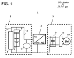
- a second subnetwork 3 in which a second mains voltage U2 is applied and in which an electrical machine 10 is provided.
- the electric machine 10 is for starting an internal combustion engine (not shown) of the motor vehicle and the generator operation or Rekuperations réelle educated.
- a second energy store 9 is further provided, which is connected to the electric machine 10 via an inverter 11.
- the second energy store 9 is designed to store electrical charge generated by the electric machine 10 in the generator operation or recuperation operation.
- the energy storage 9 is designed as a double-layer capacitor.
- the first energy storage 5 is also designed as a capacitor storage.
- the power lines 12 are in FIG. 1 marked with solid black lines.
- the vehicle electrical system 1 further comprises a voltage converter 4, which connects the first subnetwork 2 bidirectionally with the second subnetwork 3.
- the voltage converter 4 is designed to receive a DC voltage from one of the subnetworks 2, 3, for example a DC voltage with which the first subnetwork 2 is operated, and to generate an output voltage which is different from the voltage received on the input side.
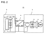
- the starter 7 for the internal combustion engine can also be provided in the second subnetwork 3, the island grid. This is in the embodiment of a vehicle electrical system 21 of FIG. 2 illustrated that differs from that in FIG. 1 illustrated embodiment differs in that the starter 7 is arranged in the second sub-network 3.
- the electrical system 1 or 21 may further comprise a control unit (not shown), which is connected via corresponding signal lines (not shown) with the corresponding components of the electrical system 1, 21, in particular the voltage converter 4, the charge sensor 8, the energy storage 5 and 9 and the electric machine 10.
- the control unit receives from the energy stores 5, 9 or the charge state sensor 8 and from a storage management system (not shown) of the energy store 9 data on the state of charge of the energy storage 5, 9.
- the control unit is further configured to the voltage converter 4 in response to the received charge states to issue corresponding control signals.
- the voltage converter 4 is set up to transmit energy from the first subnetwork 2 into the second subnetwork 3 and vice versa. In particular, energy can be transmitted from the first energy store 5 to the second energy store 9 via the voltage converter and vice versa.
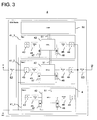
- FIG. 3 shows an advantageous embodiment of the voltage converter 4.
- the voltage converter is designed as a DC / DC converter and includes a central controller 50th
- the voltage converter further includes parallel-connected sub-components 41, in FIG. 3 also referred to as phases which, in interaction, represent the total voltage converter function of the voltage converter 4.
- Each of the individual phases 41_1 to 41_n consists of a central voltage converter element 42, an input-side switch 43 and an output-side switch 44.
- the switch 43 With the switch 43, the respective subcomponent 41 can be disconnected from the first subnet 2 in the event of a malfunction in the subcomponent 41 or a short circuit , Accordingly, with the second switch 44, the subcomponent 41 can be separated from the second subnet 3.
- each measuring elements 45, 46 arranged to measure the current and the voltage in the respective sub-element 41. Furthermore, upstream and downstream of the voltage converter element 42 capacitors 47, 48 are provided, each serving as a buffer to dampen voltage spikes and to compensate for a voltage ripple.
- the voltage converter 4 also has two U / I measuring devices 52, 53 in order to determine a voltage and the current at the network node of the voltage converter 4 to the first and the second sub-network 2, 3.
- Each of the voltage converter elements 42 also has an input for an input signal 51 of the controller 50, via which the controller 50 controls the respective voltage converter element 42.
- the switches 43, 44 and the measuring devices 45, 46, 52, 53 are likewise connected to the controller 50 via signal lines (not shown). Based on the received measured values of the measuring devices 45, 46, 52, 53 concerning the current and / or the voltage in the phases 41 or at the network node, the controller 50 can determine the current load on the voltage converter 4 or on the individual phases 41 and / or determine whether an error occurs in one of the phases 41.
- the corresponding phase can be separated by the controller 50 from the first subnet 2 and / or from the second subnet 3 by the switches 43 and 44. This prevents that in the event of a fault of the DC / DC converter 4 to a short circuit between the first subnet 2 and the second subnet 3, a short circuit between the first subnet 2 and ground (GND) or a short circuit between the second subnet 3 and Ground (GND) is coming.
- the functional independence of the individual phases can be determined by determining the measured values for current and voltage (determined either via the measurement U / I in the phases 41 or at the network node by the measuring units 52, 53) are determined by the controller 50, the applied load scenario so that it can if necessary individual phases via the signal lines 51 on or off. This results in the possibility, in comparison with previously determined efficiency maps, to operate the system network centrally controlled by the controller 50 in the best efficiency range. Furthermore, in case of failure / failure of a phase 41, the total power can no longer be displayed, but a reduced performance is maintained. This ensures that the DC / DC converter 4 has a high efficiency over its entire power spectrum. This is particularly important in city buses, where the power spectrum of the electrical system is very wide and the distribution of services retrieved is very uniform.
Abstract
Die Erfindung betrifft ein Bordnetz (1) eines Kraftfahrzeugs sowie ein Verfahren zum Betrieb eines Bordnetzes für ein Kraftfahrzeug, insbesondere für ein Nutzfahrzeug. Das Bordnetz (1) umfasst ein erstes Teilnetz (2), in dem eine erste Nennspannung (U1) anliegt, ein zweites Teilnetz (3), in dem eine zweite Nennspannung (U2) anliegt, und einen Spannungswandler (4), der das erste Teilnetz (2) mit dem zweiten Teilnetz (3) bidirektional verbindet. Das erste Teilnetz (2) umfasst einen ersten Energiespeicher (5) und einen ersten, durch mehrere Verbraucher gebildeten, Lastwiderstand (6). Das zweite Teilnetz (3) umfasst eine elektrischen Maschine (10), die zum Starten eines Verbrennungsmotors des Kraftfahrzeugs und zum Generatorbetrieb bzw. Rekuperationsbetrieb ausgebildet ist, und einen zweiten Energiespeicher (9), der mit der elektrischen Maschine (10) verbunden und ausgebildet ist, von der elektrischen Maschine (10) in dem Generatorbetrieb bzw. Rekuperationsbetrieb erzeugte elektrische Ladung zu speichern. Der Spannungswandler (4) ist ausgebildet, in Abhängigkeit eines Ladezustands des ersten Energiespeichers (5) und/oder eines Ladezustands des zweiten Energiespeichers (9) Energie über den Spannungswandler (12) zwischen dem ersten (2) und zweiten (3) Teilnetz zu übertragen.The invention relates to an electrical system (1) of a motor vehicle and to a method for operating a vehicle electrical system for a motor vehicle, in particular for a commercial vehicle. The vehicle electrical system (1) comprises a first subnetwork (2) in which a first rated voltage (U1) is applied, a second subnetwork (3) in which a second rated voltage (U2) is applied, and a voltage converter (4) which is the first Subnet (2) to the second subnet (3) connects bidirectionally. The first subnetwork (2) comprises a first energy store (5) and a first load resistor (6) formed by a plurality of consumers. The second subnetwork (3) comprises an electrical machine (10), which is designed to start an internal combustion engine of the motor vehicle and for generator operation or recuperation operation, and a second energy store (9), which is connected to the electric machine (10) and formed to store electric charge generated by the electric machine (10) in the generator operation or recuperation operation. The voltage converter (4) is designed to transmit energy via the voltage converter (12) between the first (2) and second (3) subnetwork as a function of a charge state of the first energy store (5) and / or a charge state of the second energy store (9) ,
Description
Die Erfindung betrifft ein Bordnetz für ein Kraftfahrzeug, insbesondere für ein Nutzfahrzeug. Die Erfindung betrifft weiterhin ein Verfahren zum Betrieb eines Bordnetzes.The invention relates to a vehicle electrical system for a motor vehicle, in particular for a commercial vehicle. The invention further relates to a method for operating a vehicle electrical system.
Fahrzeuge müssen zunehmend hohe Anforderungen hinsichtlich der Reduktion des Kraftstoffverbrauchs und der Emissionen bei hohem Fahrkomfort erfüllen. Um dieses Ziel zu erreichen, ist es aus dem Stand der Technik bekannt, Fahrzeuge mit Start/Stopp- und Rekuperationssystemen auszurüsten. Bei derzeitigen Fahrzeugen werden die Rekuperationsmodule und Starter-Generatoren üblicherweise direkt an das Bordnetz angeschlossen. Dadurch ergeben sich Rückkopplungen auf das Bordnetz, wie beispielsweise Spannungseinbrüche beim Motorstart (Warm- und Kaltstart) oder Bordnetzwelligkeiten beim Rekuperieren, die durch einen angepassten Bordnetzspeicher abgemildert werden. Bei diesen Systemen entspricht die Spannungslage der Start/Stopp-Komponenten und des Energiespeichers der Bordnetzspannung.Vehicles must meet increasingly stringent requirements with regard to the reduction of fuel consumption and emissions with a high level of driving comfort. To achieve this goal, it is known from the prior art to equip vehicles with start / stop and Rekuperationssystemen. In current vehicles, the recuperation modules and starter generators are usually connected directly to the electrical system. This results in feedback on the electrical system, such as voltage drops during engine start (warm and cold start) or electrical system ripple during recuperation, which are mitigated by an adapted on-board network storage. In these systems, the voltage level of the start / stop components and the energy storage corresponds to the vehicle electrical system voltage.
Eine Aufgabe der Erfindung ist es, ein Kraftfahrzeugbordnetz bereitzustellen, das Nachteile herkömmlicher Kraftfahrzeugbordnetze vermeidet. Das Kraftfahrzeugbordnetz soll insbesondere einen Start/Stopp-Betrieb ohne Spannungseinbrüche, ohne Bordnetzwelligkeiten beim Rekuperieren und ohne zusätzlichen Verschleiß ermöglichen. Eine weitere Aufgabe ist es, ein Verfahren zum Betrieb eines Bordnetzes bereitzustellen, das Nachteile herkömmlicher Verfahren vermeidet.An object of the invention is to provide a vehicle electrical system that avoids disadvantages of conventional motor vehicle electrical systems. The motor vehicle electrical system should in particular enable a start / stop operation without voltage dips, without electrical system ripple during recuperation and without additional wear. Another object is to provide a method for operating a vehicle electrical system, which avoids the disadvantages of conventional methods.
Diese Aufgaben werden durch ein Bordnetz und ein Verfahren mit den Merkmalen der unabhängigen Ansprüche gelöst. Vorteilhafte Ausführungsformen und Anwendungen der Erfindung sind Gegenstand der abhängigen Ansprüche und werden in der folgenden Beschreibung unter teilweiser Bezugnahme auf die Figuren näher erläutert.These objects are achieved by a vehicle electrical system and a method having the features of the independent claims. Advantageous embodiments and applications of the invention are the subject matter of the dependent claims and are explained in more detail in the following description with partial reference to the figures.
Gemäß allgemeinen Gesichtspunkten der Erfindung zeichnet sich die erfindungsgemäße Bordnetztopologie dadurch aus, dass das erfindungsgemäße Bordnetz für ein Kraftfahrzeug zwei Teilnetze umfasst: Ein erstes Teilnetz, nachfolgend auch als Hauptnetz bezeichnet, in dem eine erste Nennspannung U1 anliegt, und ein zweites Teilnetz, nachfolgend auch als Inselnetz bezeichnet, in dem eine zweite Nennspannung U2 anliegt.According to general aspects of the invention, the on-board network topology according to the invention is characterized in that the vehicle electrical system according to the invention comprises two subnetworks for a motor vehicle: a first subnetwork, also referred to as the main network in which a first rated voltage U1 is present, and a second subnetwork, also referred to below Is island network referred to, in which a second rated voltage U2 is applied.
Das erste Teilnetz umfasst einen ersten Energiespeicher und einen Lastwiderstand, der durch wenigstens einen, vorzugsweise aber durch mehrere Verbraucher gebildet wird. Das zweite Teilnetz umfasst eine elektrische Maschine, die zum Starten eines Verbrennungsmotors des Kraftfahrzeugs und zum Generatorbetrieb bzw. Rekuperationsbetrieb ausgebildet ist. Das zweite Teilnetz umfasst ferner einen Energiespeicher, der mit der elektrischen Maschine incl. zugehöriger Elektronik verbunden und ausgebildet ist, die von der elektrischen Maschine in dem Generatorbetrieb bzw. Rekuperationsbetrieb erzeugte elektrische Ladung zu speichern.The first subnetwork comprises a first energy store and a load resistor, which is formed by at least one, but preferably by a plurality of consumers. The second subnetwork comprises an electrical machine which is designed to start an internal combustion engine of the motor vehicle and for generator operation or recuperation operation. The second subnet further comprises an energy store, which is connected to the electrical machine incl. Associated electronics and is designed to store the electrical charge generated by the electric machine in the generator operation or recuperation.
Ferner umfasst das Bordnetz einen Spannungswandler, vorzugsweise einen DC/DC-Wandler, der das erste Teilnetz mit dem zweiten Teilnetz bidirektional verbindet und mindestens mittelbar mit dem ersten Energiespeicher und dem zweiten Energiespeicher verbunden ist. Hierbei ist der Spannungswandler ausgebildet, in Abhängigkeit eines Ladezustands des ersten Energiespeichers und/oder eines Ladezustands des zweiten Energiespeichers Energie über den Spannungswandler zwischen dem ersten und dem zweiten Teilnetz zu übertragen, beispielsweise zwischen den ersten und zweiten Energiespeichern oder von dem zweiten Energiespeicher zu dem Lastwiderstand im Hauptnetz.Furthermore, the vehicle electrical system comprises a voltage converter, preferably a DC / DC converter, which connects the first subnetwork bidirectionally with the second subnetwork and is connected at least indirectly to the first energy store and the second energy store. In this case, the voltage converter is designed to transmit energy as a function of a state of charge of the first energy store and / or a state of charge of the second energy store via the voltage converter between the first and the second subnet, for example between the first and second energy stores or from the second energy store to the load resistor in the main network.
Vorzugsweise ist die Nennspannung U2 größer als die Nennspannung U1. Beispielsweise kann die im zweiten Teilnetz anliegende Nennspannung 48 V betragen, während die Nennspannung im ersten Teilnetz die üblichen 24 V beträgt. Da die Spannungslage des zweiten Teilnetzes erhöht werden kann, beispielsweise auf 48 V, ist es energetisch vorteilhaft, weitere leistungsstarke Nebenverbraucher in das zweite Teilnetz zu integrieren.Preferably, the rated voltage U2 is greater than the rated voltage U1. By way of example, the nominal voltage applied in the second subsystem can be 48 V, while the nominal voltage in the first subsystem is the usual 24 V. Since the voltage level of the second subnet can be increased, for example, to 48 V, it is energetically advantageous to integrate more powerful secondary consumers in the second subnet.
Durch das Vorsehen des zweiten Teilnetzes wird somit ein von der Bordnetzspannung im Hauptnetz bzw. ersten Teilnetz unabhängiges Inselnetz bereitgestellt, das von diesem durch einen Spannungswandler getrennt ist. Die erfindungsgemäße Bordnetztopologie entkoppelt somit das Start/Stopp-System und den Rekuperationsspeicher vom Hauptnetz. Dadurch können durch den Rekuperations- und/oder den Start/Stopp-Mechanismus bedingte Störeinflüsse, wie Spannungseinbrüche beim Motorstart oder Bordnetzwelligkeiten beim Rekuperieren, im Hauptnetz zuverlässig vermieden werden, da diese auf das zweite Teilnetz beschränkt bleiben. Der Spannungswandler ist vorzugsweise mit einer Leistungselektronik versehen, die bei Rekuperations- und Start/Stopp-Vorgängen des Fahrzeugs auftretende Spannungseinbrüche und Bordnetzwelligkeiten herausfiltert und nicht an das erste Teilnetz weitergibt. Dadurch kann auch einer vorzeitigen Alterung des im ersten Teilnetz befindlichen Energiespeichers vorgebeugt werden.The provision of the second subnetwork thus provides an island network which is independent of the vehicle electrical system voltage in the main network or first subnetwork and which is separated therefrom by a voltage converter. The on-board network topology according to the invention thus decouples the start / stop system and the recuperation memory from the main network. As a result, by the Rekuperations- and / or the start / stop mechanism related interference, such as voltage dips during engine start or electrical system ripple during recuperation, can be reliably avoided in the main network, as they remain limited to the second subnet. The voltage converter is preferably provided with power electronics which filters out voltage dips and electrical system ripples occurring during recuperation and start / stop operations of the vehicle and does not transmit them to the first subnet. As a result, premature aging of the energy store located in the first subnetwork can also be prevented.
Somit sind die Komponenten für den Start/Stopp-Betrieb und die Rekuperation unabhängig von der Bordnetzspannung U1 und folglich nicht durch eine Maximalleistung der Bordnetzspannung U1 beschränkt. Da die Rekuperation innerhalb des zweiten Teilnetzes erfolgt, ist diese auch unabhängig vom Wirkungsgrad des Spannungswandlers, da die rekuperierte Energie direkt im zweiten Teilnetz durch den zweiten Energiespeicher aufgenommen werden kann und nicht durch den Spannungswandler hindurchgeleitet werden muss.Thus, the components for start / stop operation and recuperation are independent of the vehicle electrical system voltage U1 and consequently not limited by a maximum power of the vehicle electrical system voltage U1. Since the recuperation takes place within the second subnet, this is also independent of the efficiency of the voltage converter, since the recuperated energy can be absorbed directly in the second subnet by the second energy storage and must not be passed through the voltage converter.
Für den Start des Verbrennungsmotors, insbesondere für den Kaltstart, kann weiterhin ein konventioneller Starter vorgesehen sein. Für eine verbesserte Lebensdauer der Batterie ist der Starter vorzugsweise im zweiten Teilnetz vorgesehen. Dies hat ferner den Vorteil, dass Länge und Querschnitt von entsprechenden Anschlusskabeln reduziert werden können. So kann beispielsweise im zweiten Teilnetz eine höhere Spannung eingesetzt werden, die geringere Starterströme zum Erbringen der Starterleistung erfordert und es somit ermöglicht, den Querschnitt der entsprechenden Kabel zu reduzieren. Ein weiterer Vorteil der Anordnung des konventionellen Starters im zweiten Teilnetz ist, dass eine bessere Kaltstartfähigkeit erzielt wird und beim Start im Hauptnetz kein oder nur ein geringer Spannungseinbruch auftritt. Ferner hat dies eine geringere Alterung des ersten Speichers im Hauptnetz zur Folge und ermöglicht eine geringere Abhängigkeit von der Lebensdauer des ersten Speichers. Der Starter kann jedoch auch im ersten Teilnetz angeordnet sein.For the start of the internal combustion engine, in particular for the cold start, a conventional starter may continue to be provided. For an improved life of the battery, the starter is preferably provided in the second subnet. This also has the advantage that length and cross-section of corresponding connection cables can be reduced. Thus, for example, a higher voltage can be used in the second sub-network, which requires smaller starter currents for providing the starter power and thus makes it possible to reduce the cross-section of the corresponding cables. Another advantage of the arrangement of the conventional starter in the second subnet is that a better cold start capability is achieved and no or only a small voltage dip occurs when starting in the main network. Furthermore, this results in less aging of the first memory in the main network and allows less dependence on the life of the first memory. However, the starter can also be arranged in the first subnet.
Gemäß einer vorteilhaften Ausführungsform ist das Bordnetz so ausgebildet, dass die elektrische Maschine den Starter beim Startvorgang unterstützt, indem Starter und elektrische Maschine gleichzeitig zum Kaltstartvorgang ihr Moment in den Verbrennungsmotor einprägen. Eine weitere Möglichkeit zur Kaltstart-Unterstützung wäre, wenn der Starter im ersten Teilnetz unterstützend durch den DC/DC-Wandler aus dem zweiten Teilnetz mit Energie versorgt wird, zusätzlich zur Leistungsbereitstellung aus Netz U1.According to an advantageous embodiment, the vehicle electrical system is designed so that the electric machine supports the starter during the starting process by simultaneously impressing the starter and electric machine for cold start their moment in the engine. Another option for cold start support would be if the starter in the first subnet is supported by the DC / DC converter from the second subnet in addition to the power supply from network U1.
Gemäß einem bevorzugten Ausführungsbeispiel ist im ersten Teilnetz ein Sensor zur Überwachung des Ladezustands des ersten Energiespeichers vorgesehen. Dies ermöglicht eine genaue Erfassung des Ladezustands des ersten Speichers unabhängig von Bordnetzwelligkeiten und anderen Störeffekten. Alternativ kann auch der Spannungswandler eingerichtet sein, den Ladungszustand des ersten Speichers in Abhängigkeit der am Spannungswandler anliegenden Spannung zu erfassen, die an diesem an der dem ersten Teilnetz zugewandten Seite anliegt. Zur genauen Bestimmung des Ladungszustandes dieses Speichers muss die Speicherleerlaufspannung gemessen werden.According to a preferred embodiment, a sensor for monitoring the state of charge of the first energy storage is provided in the first subnet. This allows an accurate detection of the state of charge of the first memory regardless of electrical system ripple and other interference effects. Alternatively, the voltage converter can also be set up to detect the state of charge of the first memory as a function of the voltage applied to the voltage converter, which voltage is applied thereto at the side facing the first subnetwork. For accurate determination of the state of charge of this storage tank, the storage idling voltage must be measured.
Der in dem zweiten Teilnetz vorzugsweise verwendete Speicher, wie beispielsweise ein Doppelschichtkondensator, ist in der Regel mit einem eigenen Speichermanagementsystem ausgestattet, das einen genauen Wert für den Ladungszustand des zweiten Energiespeichers fortlaufend ermittelt. Alternativ kann jedoch auch der Spannungswandler ausgebildet sein, den Ladungszustand des zweiten Speichers aus einer am Spannungswandler anliegenden Spannung zu erfassen. Hierbei wird die Spannung, die an der dem zweiten Teilnetz zugewandten Seite am Spannungswandler anliegt, zu einem Zeitpunkt erfasst, wenn die elektrische Maschine das zweite Teilnetz nicht belastet, z. B. beim Stand des Fahrzeugs.The memory preferably used in the second subsystem, such as a double-layer capacitor, is usually equipped with its own memory management system, which continuously determines an accurate value for the state of charge of the second energy store. Alternatively, however, the voltage converter can also be designed to detect the charge state of the second memory from a voltage present at the voltage converter. In this case, the voltage applied to the second subnetwork side facing the voltage converter, detected at a time when the electric machine does not load the second subnet, z. B. in the state of the vehicle.
Gemäß einem bevorzugten Ausführungsbeispiel enthält der Spannungswandler eine zentrale Steuerung und n parallel geschaltete, als Spannungswandler ausgebildete Subkomponenten, die nachfolgend auch als Phasen bezeichnet werden, wobei n ≥ 1 ist. Weiter vorzugsweise ist n ≥ 2, weiter vorzugsweise ≥ 5.According to a preferred embodiment, the voltage converter comprises a central controller and n parallel components designed as voltage transformers, which are also referred to below as phases, where n ≥ 1. More preferably, n ≥ 2, more preferably ≥ 5.
Dies verbessert die Ausfallsicherheit und die Verfügbarkeit des Bordnetzes. So können gemäß einer vorteilhaften Variante dieser Ausgestaltungsform einzelne Subkomponenten durch die Steuerung zu- oder abgeschaltet werden, falls eine Fehlfunktion in einer dieser Komponenten vorliegt oder um einen Kurzschluss zwischen dem ersten Teilnetz und dem zweiten Teilnetz oder einen Kurzschluss zwischen dem ersten Teilnetz und Masse oder einen Kurzschluss zwischen dem zweiten Teilnetz und Masse zu vermeiden.This improves the reliability and availability of the electrical system. Thus, according to an advantageous variant of this embodiment, individual subcomponents can be switched on or off by the controller if there is a malfunction in one of these components or a short circuit between the first subnet and the second subnet or a short circuit between the first subnet and ground or one Short circuit between the second subnet and ground to avoid.
Ein besonderer Vorzug dieser Ausführungsform liegt ferner darin, dass die Steuerung ausgebildet sein kann, in Abhängigkeit einer an dem Spannungswandler anliegenden Last einzelne Subkomponenten zu- oder abzuschalten. Hierdurch kann der Spannungswandler an unterschiedliche Leistungsanforderungen für den Energietransfer von dem ersten Teilnetz in das zweite Teilnetz und umgekehrt dynamisch angepasst werden.A particular advantage of this embodiment is further that the controller may be configured to switch on or off individual subcomponents in dependence on a load applied to the voltage converter. As a result, the voltage converter can be adapted dynamically to different power requirements for the energy transfer from the first subnet to the second subnet and vice versa.
Eine Möglichkeit der erfindungsgemäßen Realisierung sieht hierbei vor, dass zumindest eine oder vorzugsweise jede der Subkomponenten mindestens eine U/I-Messeinrichtung aufweist, um eine Spannung und/oder einen Strom der Subkomponente zu bestimmen. Besonders vorteilhaft ist, wenn jede Subkomponente zwei derartige U/I-Messeinrichtungen aufweist: eine eingangsseitig angeordnete U/I-Messeinrichtung, d. h. stromauf des Spannungswandlerelements der Subkomponente und eine ausgangsseitig angeordnete U/I-Messeinrichtung, d. h. stromab des Spannungswandlerelements der Subkomponente.One possibility of the implementation according to the invention provides here that at least one or preferably each of the subcomponents has at least one U / I measuring device in order to determine a voltage and / or a current of the subcomponent. It is particularly advantageous if each subcomponent has two such U / I measuring devices: a U / I measuring device arranged on the input side, ie upstream of the voltage converter element of the subcomponent and a U / I measuring device arranged on the output side, ie downstream of the voltage converter element of the subcomponent.
Gemäß einer weiteren Variante kann eine weitere U/I-Messeinrichtung vorgesehen sein, um eine Spannung und/oder einen Strom an einem Netzknoten des Spannungswandlers zu dem ersten und/oder dem zweiten Teilnetz zu bestimmen. Besonders vorteilhaft ist es, wenn an beiden Netzknoten, d. h. an dem Knoten zum ersten Teilnetz und an dem Knoten zum zweiten Teilnetz, jeweils eine U/I-Messvorrichtung vorgesehen ist.According to a further variant, a further U / I measuring device can be provided in order to determine a voltage and / or a current at a network node of the voltage converter to the first and / or the second subnet. It is particularly advantageous if at both network nodes, d. H. at the node to the first subnet and at the node to the second subnet, in each case a U / I measuring device is provided.
Durch die funktionelle Unabhängigkeit der einzelnen Subkomponenten bzw. Phasen kann eine derartige Messung der anliegenden Spannung oder des fließenden Stroms in den Subkomponenten oder an den Knoten verwendet werden, um das anliegende Last-Szenario durch die Steuerung des Spannungswandlers zu ermitteln, um so bei Bedarf einzelne Phasen zu- oder abzuschalten. Dadurch ergibt sich die Möglichkeit, in Abgleich mit vorher ermittelten Wirkungsgradkennfeldern den Systemverbund zentral gesteuert im besten Wirkungsgradbereich zu betreiben. Des Weiteren kann bei einem Ausfall/Fehler einer Subkomponente die Gesamtleistung zwar nicht mehr dargestellt werden, aber eine reduzierte Leistungsfähigkeit bleibt dennoch erhalten, um so eine verbesserte Ausfallsicherheit zu realisieren.Due to the functional independence of the individual subcomponents or phases, such a measurement of the applied voltage or of the flowing current in the subcomponents or at the node can be used to determine the applied load scenario by the control of the voltage converter, so as to be individual To switch phases on or off. This results in the possibility of operating the system group centrally controlled in the best efficiency range in comparison with previously determined efficiency maps. Furthermore, in the event of a failure / failure of a subcomponent, the overall performance can no longer be represented, but a reduced performance is still maintained in order to realize an improved reliability.
Eine weitere Möglichkeit der erfindungsgemäßen Realisierung sieht vor, dass mindestens eine der Subkomponenten unidirektional ausgebildet ist. Auf diese Weise kann auf konstruktiv einfache Weise eine unterschiedliche Leistungsfähigkeit des Spannungswandlers zum Übertragen von Leistung vom ersten ins zweite Teilnetz versus der Leistungsfähigkeit zur Übertragung von Leistung vom zweiten ins erste Teilnetz umgesetzt werden. Vorzugsweise ist der Spannungswandler gemäß dieser Variante so ausgelegt, dass die Leistungsfähigkeit vom ersten ins zweite Teilnetz größer ist als die Leistungsfähigkeit vom zweiten ins erste Teilnetz.Another possibility of implementation according to the invention provides that at least one of the sub-components is unidirectional. In this way, a different performance of the voltage converter for transmitting power from the first to the second subnet versus the power to transmit power from the second to the first subnet can be implemented in a structurally simple manner. Preferably, the voltage converter according to this variant is designed so that the performance of the first to the second subnet is greater than the performance of the second to the first subnet.
Die zuvor beschriebenen Ausführungsvarianten können durch einen Spannungswandler, der als ein Gerät bzw. als bauliche Einheit ausgebildet ist oder durch entsprechend verschaltete Einzelgeräte realisiert werden.The embodiments described above can be realized by a voltage converter, which is designed as a device or as a structural unit or by appropriately interconnected individual devices.
Der erste Energiespeicher kann als ein herkömmlicher Bleiakkumulator, als ein Lithiumionen-akkumulator oder auch als ein Kondensatorspeicher ausgebildet sein. Der zweite Energiespeicher ist vorzugsweise ein Doppelschichtkondensator (EDLC-Speicher), ein Superkondensator oder ein Lithiumionen-Akkumulator.The first energy store may be designed as a conventional lead-acid battery, as a lithium ion accumulator or as a capacitor storage. The second energy store is preferably a double-layer capacitor (EDLC memory), a supercapacitor or a lithium ion secondary battery.
Gemäß einem bevorzugten Ausführungsbeispiel ist das Bordnetz ausgebildet, Energie aus dem ersten Energiespeicher über den Spannungswandler in den zweiten Energiespeicher zu übertragen. Vorzugsweise wird auf diese Weise Energie aus dem ersten Energiespeicher in den zweiten Energiespeicher über den Spannungswandler übertragen, wenn ein Ladezustand in dem zweiten Energiespeicher einen ersten vorbestimmten Schwellwert unterschreitet. Dadurch kann sichergestellt werden, dass stets genügend Energie im zweiten Speicher vorrätig ist, um das erste Teilnetz bzw. die darin befindlichen Verbraucher auch im Stand bei ausgeschaltetem Verbrennungsmotor zu versorgen. Ferner wird sichergestellt, dass im zweiten Speicher genügend Energie vorrätig ist, um einen Warmstart mit der elektrischen Maschine durchzuführen.According to a preferred embodiment, the vehicle electrical system is configured to supply energy from the first energy store via the voltage converter into the second energy store transfer. Preferably, in this way, energy is transferred from the first energy store into the second energy store via the voltage converter when a charge state in the second energy store falls below a first predetermined threshold value. This can ensure that sufficient energy is always available in the second memory in order to supply the first subnet or the consumers therein even when the internal combustion engine is switched off. Furthermore, it is ensured that sufficient energy is available in the second memory to perform a warm start with the electric machine.
Bei einer vorteilhaften Variante dieser Ausgestaltungsform wird ferner vom Bordnetz geprüft, ob der Ladungszustand des ersten Energiespeichers unter einen zweiten vorbestimmten Wert gefallen ist. Gemäß dieser Ausführungsform wird nur Energie in den zweiten Energiespeicher übertragen, wenn der Ladezustand in dem ersten Energiespeicher noch nicht unter den zweiten vorbestimmten Wert gefallen ist. Wenn der Ladungszustand des ersten Energiespeichers unter den zweiten vorbestimmten Wert gefallen ist, kann stattdessen ein Motorstart, beispielsweise im Leerlauf, erzwungen werden, um ein zu starkes Entladen der Energiespeicher zu verhindern. Die beschriebene Ausführungsvarianten ermöglichen somit eine längere Stoppdauer des Fahrzeugs, bevor ein Motorstart erzwungen wird.In an advantageous variant of this embodiment, it is further checked by the electrical system, whether the state of charge of the first energy storage has fallen below a second predetermined value. According to this embodiment, only energy is transferred into the second energy store when the state of charge in the first energy store has not fallen below the second predetermined value. If the state of charge of the first energy store has dropped below the second predetermined value, an engine start, for example, at idle, can instead be forced in order to prevent overcharging of the energy stores. The described embodiments thus allow a longer stop duration of the vehicle before an engine start is forced.
Eine weitere vorteilhafte Ausführungsvariante sieht vor, Energie vom ersten Energiespeicher über den Spannungswandler in den zweiten Energiespeicher zu übertragen, wenn ermittelt wird, dass der erste Energiespeicher nicht mehr in der Lage ist, ausreichend Leistung für den Start des Verbrennungsmotors zu liefern. Dies kann z. B. der Fall bei einem gealterten leistungsschwachen ersten Speicher sein, der nicht mehr in der Lage ist, die für einen Startvorgang kurzfristig hohe Startleistung, beispielsweise 12 kW, bereitzustellen. Mittels der erfindungsgemäßen Bordnetztopologie kann die Restladung im ersten Speicher mit geringerer Leistung über einen längeren Zeitraum entnommen und über den Spannungswandler an den zweiten Energiespeicher übertragen werden. Auf diese Weise kann selbst bei starker Entladung beider Energiespeicher somit verbleibende Restladung gebündelt werden, um ein Starten des Motors zu ermöglichen, die dann über den elektrischen Motor im zweiten Teilnetz erfolgt.A further advantageous embodiment provides to transfer energy from the first energy storage via the voltage converter in the second energy storage, if it is determined that the first energy storage is no longer able to provide sufficient power for the start of the engine. This can be z. Example, be the case with an aged low-performance first memory, which is no longer able to provide the short-start power for a startup operation, for example, 12 kW. By means of the on-board network topology according to the invention, the residual charge can be removed in the first memory with lower power over a longer period and transmitted via the voltage converter to the second energy storage. In this way, even with strong discharge of both energy storage thus remaining residual charge can be bundled to allow starting of the engine, which then takes place via the electric motor in the second subnet.
Gemäß einer weiteren Variante ist das Bordnetz ausgebildet, in dem zweiten Energiespeicher nicht aufnehmbare, rekuperierte Energie von dem Spannungswandler in das erste Teilnetz zu übertragen. Dadurch kann die Energieeffizienz des Fahrzeugs verbessert werden, da vermieden wird, dass die Energie, die beim Abbremsen der Fahrzeugs entsteht, bei vollgeladenem zweiten Energiespeicher mittels der Bremsen des Fahrzeugs oder des Antriebsmotors in Verlustwärme umgesetzt wird.According to a further variant, the vehicle electrical system is designed to transmit non-absorbable, recuperated energy from the voltage converter into the first subnet in the second energy store. This can improve the energy efficiency of the vehicle by preventing the energy generated when the vehicle is decelerating from becoming fully charged second energy storage is converted by means of the brakes of the vehicle or the drive motor in heat loss.
Vorzugsweise ist das Bordnetz weiter ausgebildet, während des Fahrbetriebs im zweiten Speicher gespeicherte Energie zur Versorgung des ersten Lastwiderstands an das erste Teilnetz zu übertragen. Insbesondere beim Stopp des Fahrzeugs kann die verwendete rekuperierte Energie des zweiten Energiespeichers zur Versorgung der Verbraucher im ersten Teilnetz vorteilhaft eingesetzt werden. Dadurch kann wirksam ein vorzeitiges Altern des Energiespeichers im ersten Teilnetz verhindert werden.Preferably, the electrical system is further configured to transmit stored energy during the driving operation in the second memory for supplying the first load resistance to the first subnet. In particular, when the vehicle is stopped, the used recuperated energy of the second energy store can be advantageously used to supply the consumers in the first subnetwork. This can effectively prevent premature aging of the energy storage in the first subnet.
Bei einer weiteren vorteilhaften Ausführungsform ist das Bordnetz ausgebildet, mittels des Spannungswandlers eine Ist-Spannung im ersten Teilnetz auf eine vorgegebene Kennlinie einzuregeln. Dies hat den Vorteil, dass z. B. der erste Speicher mit idealer Ladeschlussspannung betrieben werden kann. Ein derartiger Speicher wird abhängig von der Temperatur mit einer bestimmten Spannung geladen, wobei dieser erst strombegrenzt und anschließend in der letzten Ladephase spannungsbegrenzt angefahren wird. Die erfindungsgemäße Bordnetztopologie ermöglicht es, die vorgegebene Kennlinie durch den Spannungswandler entsprechend angesteuert anzufahren, der hierbei Energie aus dem zweiten Teilnetz ins erste Teilnetz transferiert.In a further advantageous embodiment, the electrical system is designed to regulate an actual voltage in the first subnetwork to a predetermined characteristic by means of the voltage converter. This has the advantage that z. B. the first memory can be operated with ideal charging voltage. Such a memory is charged depending on the temperature with a certain voltage, which is only current-limited and then approached voltage-limited in the last charging phase. The on-board network topology according to the invention makes it possible to appropriately drive the predetermined characteristic curve by the voltage converter, which in this case transfers energy from the second subnetwork into the first subnetwork.
Das Bordnetz umfasst vorzugsweise eine Steuereinheit zur Steuerung der Komponenten des Bordnetzes, beispielsweise zur Steuerung des Bordnetzes gemäß den vorgenannten Ausführungsbeispielen. Die Steuereinheit ist mit den einzelnen Komponenten des ersten und zweiten Bordnetzes über Signalleitungen verbunden. Insbesondere empfängt die Steuereinheit über derartige Signalleitungen einen aktuellen Wert betreffend den Ladungszustand des ersten Energiespeichers und einen entsprechenden Wert betreffend den Ladungszustand des zweiten Energiespeichers. Die Steuereinheit ist vorzugsweise ausgebildet, in Abhängigkeit der empfangenen Werte über die Ladungszustände der Energiespeicher den Spannungswandler so anzusteuern, dass mittels des Spannungswandlers Energie zwischen den beiden Teilnetzen je nach Bedarf, wie vorstehend beschrieben, ausgetauscht werden kann. Insbesondere wird der Spannungswandler so angesteuert, dass dieser Energie aus dem ersten Energiespeicher in den zweiten Energiespeicher übertragen kann und umgekehrt.The electrical system preferably comprises a control unit for controlling the components of the electrical system, for example, for controlling the electrical system according to the aforementioned embodiments. The control unit is connected to the individual components of the first and second electrical system via signal lines. In particular, the control unit receives via such signal lines a current value relating to the state of charge of the first energy store and a corresponding value concerning the charge state of the second energy store. The control unit is preferably designed to control the voltage converter as a function of the received values via the charge states of the energy stores in such a way that energy can be exchanged between the two subnetworks as required by the voltage converter as described above. In particular, the voltage converter is driven so that this energy can be transferred from the first energy storage in the second energy storage and vice versa.
Ein weiterer Aspekt der vorliegenden Erfindung betrifft ein Fahrzeug, insbesondere ein Nutzfahrzeug mit einem Bordnetz nach einem der vorstehend beschriebenen Aspekte.Another aspect of the present invention relates to a vehicle, in particular a commercial vehicle with a vehicle electrical system according to one of the aspects described above.
Die Erfindung betrifft weiterhin ein Verfahren zum Betreiben eines Bordnetzes gemäß den zuvor beschriebenen Aspekten des Bordnetzes. Das Verfahren umfasst hierbei die Schritte: Erfassen des Ladezustands des ersten Energiespeichers; Erfassen des Ladezustands des zweiten Energiespeichers; und Ansteuern des Spannungswandlers in Abhängigkeit der erfassten Ladezustände der Energiespeicher, um Energie über den Spannungswandler von dem ersten Teilnetz in das zweite Teilnetz und/oder Energie vom zweiten Teilnetz in das erste Teilnetz zu übertragen. Zur Vermeidung von Wiederholungen sollen rein vorrichtungsgemäß offenbarte Merkmale auch als verfahrensgemäß offenbart gelten und beanspruchbar sein. Die vorgenannten Aspekte und erfindungsgemäßen Merkmale, insbesondere im Hinblick auf die Ausbildung des Bordnetzes zur Steuerung des Spannungswandlers betreffend die Übertragung von Energie aus dem ersten Teilnetz in das zweite Teilnetz, gelten somit auch für das Verfahren.The invention further relates to a method for operating a vehicle electrical system according to the aspects of the electrical system described above. In this case, the method comprises the steps of: detecting the state of charge of the first energy store; Detecting the state of charge of the second energy store; and driving the voltage converter as a function of the detected charge states of the energy storage to transfer energy via the voltage converter from the first subnet to the second subnet and / or energy from the second subnet to the first subnet. To avoid repetition, features disclosed purely in accordance with the device should also be disclosed as being in accordance with the method and be able to be claimed. The aforementioned aspects and features according to the invention, in particular with regard to the design of the vehicle electrical system for controlling the voltage converter with regard to the transmission of energy from the first subnet to the second subnet, thus also apply to the method.
Weitere Einzelheiten und Vorteile der Erfindung werden im Folgenden unter Bezug auf die beigefügten Zeichnungen beschrieben. Es zeigen:
Figur 1- schematisch ein Ausführungsbeispiel für ein Bordnetz eines Kraftfahrzeugs;
Figur 2- schematisch ein weiteres Ausführungsbeispiel für ein Bordnetz eines Kraftfahrzeugs; und
Figur 3- ein schematisches Blockschaltbild für einen Spannungswandler zur Verwendung in einem Bordnetz gemäß einem Ausführungsbeispiel.
- FIG. 1
- schematically an embodiment of an electrical system of a motor vehicle;
- FIG. 2
- schematically another embodiment of an electrical system of a motor vehicle; and
- FIG. 3
- a schematic block diagram of a voltage converter for use in a vehicle electrical system according to an embodiment.
Ein erstes Teilnetz 2, in dem eine erste Netzspannung U1 anliegt, und das einen ersten Energiespeicher 5 und einen Lastwiderstand 6 umfasst.Der Lastwiderstand 6 ist durch wenigstens einen, vorzugsweise durch mehrere Verbraucher gebildet.Im ersten Teilnetz 2 ist ferner ein konventioneller Starter 7 für den Verbrennungsmotor vorgesehen. Ferner weistdas erste Teilnetz 2 einenSensor 8 zur Überwachung des Ladezustands des ersten Energiespeichers 5 auf.
- A
first subnetwork 2, in which a first mains voltage U1 is present, and which comprises afirst energy store 5 and aload resistor 6. Theload resistor 6 is formed by at least one, preferably by a plurality of consumers. In thefirst subnet 2, a conventional starter 7 is also provided for the internal combustion engine. Furthermore, thefirst subnet 2 has asensor 8 for monitoring the state of charge of thefirst energy store 5.
Ferner ein zweites Teilnetz 3, in dem eine zweite Netzspannung U2 anliegt und in dem eine elektrische Maschine 10 vorgesehen ist. Die elektrische Maschine 10 ist zum Starten eines Verbrennungsmotors (nicht gezeigt) des Kraftfahrzeugs und zum Generatorbetrieb bzw. Rekuperationsbetrieb ausgebildet. Im zweiten Teilnetz 3 ist ferner ein zweiter Energiespeicher 9 vorgesehen, der mit der elektrischen Maschine 10 über einen Inverter 11 verbunden ist. Der zweite Energiespeicher 9 ist ausgebildet, von der elektrischen Maschine 10 in dem Generatorbetrieb bzw. Rekuperationsbetrieb erzeugte elektrische Ladung zu speichern. Der Energiespeicher 9 ist als Doppelschichtkondensator ausgebildet. Im vorliegenden Beispiel ist der erste Energiespeicher 5 ebenfalls als Kondensatorspeicher ausgebildet. Die Stromleitungen 12 sind in
Das Bordnetz 1 umfasst ferner einen Spannungswandler 4, der das erste Teilnetz 2 mit dem zweiten Teilnetz 3 bidirektional verbindet. Der Spannungswandler 4 ist ausgebildet, eine Gleichspannung aus einem der Teilnetze 2, 3, beispielsweise eine Gleichspannung, mit der das erste Teilnetz 2 betrieben wird, zu empfangen und eine Ausgangsspannung zu erzeugen, welche von der eingangsseitig empfangen Spannung verschieden ist.The vehicle
Der Starter 7 für den Verbrennungsmotor kann jedoch auch im zweiten Teilnetz 3, dem Inselnetz, vorgesehen sein. Dies ist in dem Ausführungsbeispiel eines Bordnetzes 21 der
Das Bordnetz 1 bzw. 21 kann ferner eine Steuereinheit (nicht gezeigt) umfassen, die über entsprechende Signalleitungen (nicht gezeigt) mit den entsprechenden Komponenten des Bordnetzes 1, 21 verbunden ist, insbesondere dem Spannungswandler 4, dem Ladungssensor 8, den Energiespeichern 5 und 9 sowie der elektrischen Maschine 10.The
Die Steuereinheit empfängt von den Energiespeichern 5, 9 bzw. dem Ladungszustandssensor 8 und von einem Speichermanagementsystem (nicht gezeigt) des Energiespeichers 9 Daten über den Ladungszustand der Energiespeicher 5, 9. Die Steuereinheit ist ferner ausgebildet, an den Spannungswandler 4 in Abhängigkeit der empfangenen Ladungszustände entsprechende Steuersignale auszugeben. In Abhängigkeit der von der Steuereinheit empfangenen Steuersignale ist der Spannungswandler 4 eingerichtet, Energie von ersten Teilnetz 2 in das zweite Teilnetz 3 zu übertragen und umgekehrt. Über den Spannungswandler kann auf diese Weise insbesondere Energie vom ersten Energiespeicher 5 zu dem zweiten Energiespeicher 9 übertragen werden und umgekehrt.The control unit receives from the
Der Spannungswandler enthält ferner parallel geschaltete Subkomponenten 41, in
Zwischen den Schaltern 43, 44 und dem Spannungswandlerelement 42 sind jeweils Messelemente 45, 46 angeordnet, um den Strom und die Spannung in dem jeweiligen Subelement 41 zu messen. Des Weiteren sind stromauf und stromab des Spannungswandlerelements 42 Kondensatoren 47, 48 vorgesehen, die jeweils als Zwischenspeicher dienen, um Spannungsspitzen zu dämpfen und um eine Spannungswelligkeit zu kompensieren. Der Spannungswandler 4 weist ferner zwei U/I-Messeinrichtungen 52, 53 auf, um eine Spannung und den Strom an den Netzknoten des Spannungswandlers 4 zu dem ersten und dem zweiten Teilnetz 2, 3 zu bestimmen.Between the
Jedes der Spannungswandlerelemente 42 weist auch einen Eingang für ein Eingangssignal 51 des Controllers 50 auf, über das der Controller 50 das jeweilige Spannungswandlerelement 42 steuert. Die Schalter 43, 44 und die Messeinrichtungen 45, 46, 52, 53 sind ebenfalls über Signalleitungen (nicht eingezeichnet) mit dem Controller 50 verbunden. Anhand der empfangenen Messwerte der Messeinrichtungen 45, 46, 52, 53 betreffend den Strom und/oder die Spannung in den Phasen 41 oder an den Netzknoten kann der Controller 50 die aktuelle Last am Spannungswandler 4 bzw. an den einzelnen Phasen 41 ermitteln und/oder bestimmen, ob ein Fehlerfall in einer der Phasen 41 vorliegt.Each of the
Im Fehlerfall innerhalb einer Phase kann durch die Schalter 43 und 44 die entsprechende Phase durch den Controller 50 vom ersten Teilnetz 2 und/oder vom zweiten Teilnetz 3 getrennt werden. Dadurch wird verhindert, dass es im Fehlerfall des DC/DC-Wandlers 4 zu einem Kurzschluss zwischen dem ersten Teilnetz 2 und dem zweiten Teilnetz 3, einem Kurzschluss zwischen dem ersten Teilnetz 2 und Masse (GND) oder einem Kurzschluss zwischen dem zweiten Teilnetz 3 und Masse (GND) kommt.In the event of a fault within a phase, the corresponding phase can be separated by the
Durch die funktionelle Unabhängigkeit der einzelnen Phasen kann über die Ermittlung der Messwerte für Strom und Spannung (ermittelt wahlweise über die Messung U/I in den Phasen 41 oder an den Netzknoten durch die Messeinheiten 52, 53) durch den Controller 50 das anliegende Lastszenario ermittelt werden, so dass dieser bei Bedarf einzelne Phasen über die Signalleitungen 51 zu- oder abschalten kann. Dadurch ergibt sich die Möglichkeit, im Abgleich mit vorher ermittelten Wirkungsgradkennfelder, den Systemverbund zentralgesteuert durch den Controller 50 im besten Wirkungsgradbereich zu betreiben. Des Weiteren kann bei Ausfall/Fehlern einer Phase 41 die Gesamtleistung nicht mehr dargestellt werden, jedoch bleibt eine reduzierte Leistungsfähigkeit erhalten. Dadurch wird sichergestellt, dass der DC/DC-Wandler 4 über sein gesamtes Leistungsspektrum einen hohen Wirkungsgrad aufweist. Dies ist speziell in Stadtbussen von Bedeutung, bei denen das Leistungsspektrum des Bordnetzes sehr breit und die Verteilung der abgerufenen Leistungen sehr gleichmäßig ist.The functional independence of the individual phases can be determined by determining the measured values for current and voltage (determined either via the measurement U / I in the
Obwohl die Erfindung unter Bezugnahme auf bestimmte Ausführungsbeispiele beschrieben worden ist, ist es für einen Fachmann ersichtlich, das verschiedene Änderungen ausgeführt werden können und Äquivalente als Ersatz verwendet werden können, ohne den Bereich der Erfindung zu verlassen. Zusätzlich können viele Modifikationen ausgeführt werden, um eine bestimmte konstruktive Ausführung des Bornetzes (Art und Anzahl der Verbraucher und deren Anordnung im ersten oder zweiten Teilnetz etc.) an die Lehre der Erfindung anzupassen, ohne den zugehörigen Bereich zu verlassen. Folglich soll die Erfindung nicht auf das offenbarte bestimmte Ausführungsbeispiel begrenzt sein, sondern die Erfindung soll alle Ausführungsbeispiele umfassen, die in den Bereich der beigefügten Patentansprüche fallen.Although the invention has been described with reference to specific embodiments, it will be apparent to those skilled in the art that various changes may be made and equivalents may be substituted for without departing from the scope of the invention. In addition, many modifications may be made to adapt a particular design of the Bornetzes (type and number of consumers and their arrangement in the first or second subnet, etc.) to the teachings of the invention without departing from the associated area. Accordingly, the invention should not be limited to the particular embodiment disclosed, but the invention is intended to embrace all embodiments which fall within the scope of the appended claims.
- 1,211.21
- Bordnetzboard network
- 22
- erstes Teilnetzfirst subnet
- 33
- zweites Teilnetzsecond subnet
- 44
- SpannungswandlerDC converter
- 55
- erster Energiespeicherfirst energy store
- 66
- Lastwiderstandload resistance
- 77
- Starterstarter
- 88th
- Sensorsensor
- 99
- zweiter Energiespeichersecond energy store
- 1010
- elektrische Maschineelectric machine
- 1111
- Inverterinverter
- 1212
- Stromleitungenpower lines
- 4141
- Subkomponenten, PhasenSubcomponents, phases
- 4242
- SpannungswandlerelementVoltage converter element
- 43, 4443, 44
- Schalterswitch
- 45, 4645, 46
- Messeinrichtungmeasuring device
- 47, 4847, 48
- Kondensatorcapacitor
- 5050
- Controllercontroller
- 5151
- Signalleitungsignal line
- 52, 5352, 53
- Messeinrichtungmeasuring device
- U1, U2U1, U2
- Nennspannungnominal voltage
Claims (15)
einem ersten Teilnetz (2), in dem eine erste Nennspannung (U1) anliegt, umfassend einen ersten Energiespeicher (5) und einen ersten, durch mehrere Verbraucher gebildeten, Lastwiderstand (6);
einem zweiten Teilnetz (3), in dem eine zweite Nennspannung (U2) anliegt, umfassend eine elektrischen Maschine (10), die zum Starten eines Verbrennungsmotors des Kraftfahrzeugs und zum Generatorbetrieb bzw. Rekuperationsbetrieb ausgebildet ist, einen zweiten Energiespeicher (9), der mit der elektrischen Maschine (10) verbunden und ausgebildet ist, von der elektrischen Maschine (10) in dem Generatorbetrieb bzw. Rekuperationsbetrieb erzeugte elektrische Ladung zu speichern; und
einem Spannungswandler (4), der das erste Teilnetz (2) mit dem zweiten Teilnetz (3) bidirektional verbindet und mindestens mittelbar mit dem ersten Energiespeicher (5) und dem zweiten Energiespeicher (9) verbunden ist, wobei der Spannungswandler (4) ausgebildet ist, in Abhängigkeit eines Ladezustands des ersten Energiespeichers (5) und/oder eines Ladezustands des zweiten Energiespeichers (9) Energie über den Spannungswandler (12) zwischen dem ersten (2) und zweiten (3) Teilnetz zu übertragen.On-board network for a motor vehicle, in particular for a commercial vehicle, with
a first subnetwork (2) in which a first rated voltage (U1) is applied, comprising a first energy store (5) and a first load resistor (6) formed by a plurality of consumers;
a second subnetwork (3), in which a second rated voltage (U2) is present, comprising an electric machine (10), which is designed to start an internal combustion engine of the motor vehicle and for generator operation or recuperation, a second energy store (9), with the electrical machine (10) is connected and configured to store electrical charge generated by the electric machine (10) in the generator operation or recuperation operation; and
a voltage converter (4) which connects the first subnetwork (2) bidirectionally to the second subnetwork (3) and is connected at least indirectly to the first energy store (5) and the second energy store (9), wherein the voltage converter (4) is formed to transmit energy via the voltage converter (12) between the first (2) and second (3) subnetwork as a function of a state of charge of the first energy store (5) and / or a state of charge of the second energy store (9).
Applications Claiming Priority (1)
| Application Number | Priority Date | Filing Date | Title |
|---|---|---|---|
| DE102013014103.6A DE102013014103A1 (en) | 2013-08-24 | 2013-08-24 | On-board network for a motor vehicle and method for operating a vehicle electrical system |
Publications (2)
| Publication Number | Publication Date |
|---|---|
| EP2840253A1 true EP2840253A1 (en) | 2015-02-25 |
| EP2840253B1 EP2840253B1 (en) | 2017-11-15 |
Family
ID=50478649
Family Applications (1)
| Application Number | Title | Priority Date | Filing Date |
|---|---|---|---|
| EP14001307.9A Active EP2840253B1 (en) | 2013-08-24 | 2014-04-10 | On-board electrical system of a motor vehicle and vehicle with such an on-board electrical system |
Country Status (2)
| Country | Link |
|---|---|
| EP (1) | EP2840253B1 (en) |
| DE (1) | DE102013014103A1 (en) |
Cited By (2)
| Publication number | Priority date | Publication date | Assignee | Title |
|---|---|---|---|---|
| WO2015172924A1 (en) * | 2014-05-13 | 2015-11-19 | Robert Bosch Gmbh | Device and method for charging two energy stores |
| WO2018162602A1 (en) * | 2017-03-08 | 2018-09-13 | Thyssenkrupp Marine Systems Gmbh | Submarine and method for operating a battery-fed electric drive system of a submarine |
Families Citing this family (3)
| Publication number | Priority date | Publication date | Assignee | Title |
|---|---|---|---|---|
| DE102016012628A1 (en) | 2016-10-21 | 2018-04-26 | Man Truck & Bus Ag | Operating method and apparatus for controlling a motor operation of an electric machine of a mild hybrid drive of a motor vehicle |
| DE102017124943A1 (en) | 2017-10-25 | 2019-04-25 | Man Truck & Bus Ag | On-board network for a motor vehicle, in particular a mild hybrid or micro hybrid vehicle |
| DE102021204233A1 (en) | 2021-04-28 | 2022-11-03 | Robert Bosch Gesellschaft mit beschränkter Haftung | battery system |
Citations (5)
| Publication number | Priority date | Publication date | Assignee | Title |
|---|---|---|---|---|
| DE10100889A1 (en) * | 2001-01-11 | 2002-07-25 | Bosch Gmbh Robert | Implementing start/stop operation of vehicles involves using two sub-supply systems, each containing an energy storage device, for supplying power when the motor is idle |
| WO2002066293A1 (en) * | 2001-02-16 | 2002-08-29 | Siemens Aktiengesellschaft | Motor vehicle electric system |
| DE102009000222A1 (en) * | 2009-01-14 | 2010-07-15 | Robert Bosch Gmbh | Vehicle electrical system and method for saving energy |
| DE102009008255A1 (en) * | 2009-02-10 | 2010-08-12 | Bayerische Motoren Werke Aktiengesellschaft | Energy on-board supply network operating method for commercial vehicle, involves conditioning voltages using non-linear elements such that charging unit charges energy storage for voltage rise by increased withdrawal of energy from network |
| DE102011083255A1 (en) * | 2011-09-23 | 2013-03-28 | Robert Bosch Gmbh | Method for operating dual-memory board network of motor vehicle by computing device, particularly control device, involves providing two sub-networks, two energy storages and starter motor that starts internal combustion engine |
-
2013
- 2013-08-24 DE DE102013014103.6A patent/DE102013014103A1/en not_active Withdrawn
-
2014
- 2014-04-10 EP EP14001307.9A patent/EP2840253B1/en active Active
Patent Citations (5)
| Publication number | Priority date | Publication date | Assignee | Title |
|---|---|---|---|---|
| DE10100889A1 (en) * | 2001-01-11 | 2002-07-25 | Bosch Gmbh Robert | Implementing start/stop operation of vehicles involves using two sub-supply systems, each containing an energy storage device, for supplying power when the motor is idle |
| WO2002066293A1 (en) * | 2001-02-16 | 2002-08-29 | Siemens Aktiengesellschaft | Motor vehicle electric system |
| DE102009000222A1 (en) * | 2009-01-14 | 2010-07-15 | Robert Bosch Gmbh | Vehicle electrical system and method for saving energy |
| DE102009008255A1 (en) * | 2009-02-10 | 2010-08-12 | Bayerische Motoren Werke Aktiengesellschaft | Energy on-board supply network operating method for commercial vehicle, involves conditioning voltages using non-linear elements such that charging unit charges energy storage for voltage rise by increased withdrawal of energy from network |
| DE102011083255A1 (en) * | 2011-09-23 | 2013-03-28 | Robert Bosch Gmbh | Method for operating dual-memory board network of motor vehicle by computing device, particularly control device, involves providing two sub-networks, two energy storages and starter motor that starts internal combustion engine |
Cited By (3)
| Publication number | Priority date | Publication date | Assignee | Title |
|---|---|---|---|---|
| WO2015172924A1 (en) * | 2014-05-13 | 2015-11-19 | Robert Bosch Gmbh | Device and method for charging two energy stores |
| WO2018162602A1 (en) * | 2017-03-08 | 2018-09-13 | Thyssenkrupp Marine Systems Gmbh | Submarine and method for operating a battery-fed electric drive system of a submarine |
| KR20190119623A (en) * | 2017-03-08 | 2019-10-22 | 티쎈크로프 마리네 지스템스 게엠베하 | Submarines and Methods for Operating Submarine Drive Systems |
Also Published As
| Publication number | Publication date |
|---|---|
| DE102013014103A1 (en) | 2015-02-26 |
| EP2840253B1 (en) | 2017-11-15 |
Similar Documents
| Publication | Publication Date | Title |
|---|---|---|
| DE102014203030B4 (en) | Method for the controlled connection of several on-board network branches of a vehicle, control unit for executing the method and vehicle on-board network | |
| EP2953227B1 (en) | Electrical system for a motor vehicle | |
| DE102013200763A1 (en) | SYSTEM AND METHOD FOR VEHICLE ENERGY MANAGEMENT | |
| WO2014086651A2 (en) | Method for the controlled connection of a plurality of on-board power system branches of a vehicle, control unit for carrying out the method and on-board power system | |
| WO2011012428A2 (en) | Circuit arrangement for an on-board system | |
| EP2840253B1 (en) | On-board electrical system of a motor vehicle and vehicle with such an on-board electrical system | |
| WO2015135729A1 (en) | Arrangement for supplying electrical energy to a motor vehicle | |
| EP3342629B1 (en) | Technique for variable connection of a traction energy storage system | |
| EP3276768B1 (en) | On-board electrical system for motor vehicles comprising a converter and a high-load consumer | |
| DE102012215755A1 (en) | Low-voltage network with DC-DC converter and method for testing a low-voltage battery | |
| EP3067240B1 (en) | Method for voltage regulation of an electrical system of a motor vehicle | |
| DE102008039284A1 (en) | Electrical-on board power supply operating method for motor vehicle, involves connecting or separating power system and energy system in dependent of function of operating conditions | |
| WO2014202326A1 (en) | Method for testing the working order of a dc link | |
| DE102016208893A1 (en) | Motor vehicle electrical system with at least two energy stores, method for operating a motor vehicle electrical system and means for its implementation | |
| WO2019192819A1 (en) | Method and device for operating a motor vehicle | |
| DE102005025616A1 (en) | Energy store`s fuel cell voltage monitoring/controlling method for motor vehicle on-board supply system, involves charging/discharging cells based on difference between determined voltage of group of cells and regulated reference voltage | |
| WO2013107560A1 (en) | On-board electrical system having a d.c. converter, control device, and associated operating method | |
| WO2016128375A1 (en) | Method for controlling a load of a low-voltage vehicle electrical system | |
| EP3075593B1 (en) | Method for discharging an electrical energy store of a motor vehicle | |
| EP3476648A1 (en) | On-board electrical system of a motor vehicle, in particular a mild hybrid or micro hybrid vehicle | |
| WO2017220233A1 (en) | Motor vehicle electrical system with at least two energy stores, method for operating a motor vehicle electrical system and means of implementation | |
| DE102020207892A1 (en) | Method for monitoring the energy supply of a motor vehicle | |
| DE102012215992A1 (en) | Electronic control unit (ECU) assembly for driving electric drive in high-voltage network, has electric drive to limit drive output voltage of electric drive on voltage reference value derived from determined voltage threshold value | |
| DE102017213856A1 (en) | Method for operating a vehicle electrical system | |
| DE102015209227A1 (en) | Method for the generator and motor operation of an electrical machine in a motor vehicle |
Legal Events
| Date | Code | Title | Description |
|---|---|---|---|
| PUAI | Public reference made under article 153(3) epc to a published international application that has entered the european phase |
Free format text: ORIGINAL CODE: 0009012 |
|
| 17P | Request for examination filed |
Effective date: 20140410 |
|
| AK | Designated contracting states |
Kind code of ref document: A1 Designated state(s): AL AT BE BG CH CY CZ DE DK EE ES FI FR GB GR HR HU IE IS IT LI LT LU LV MC MK MT NL NO PL PT RO RS SE SI SK SM TR |
|
| AX | Request for extension of the european patent |
Extension state: BA ME |
|
| R17P | Request for examination filed (corrected) |
Effective date: 20150129 |
|
| GRAP | Despatch of communication of intention to grant a patent |
Free format text: ORIGINAL CODE: EPIDOSNIGR1 |
|
| STAA | Information on the status of an ep patent application or granted ep patent |
Free format text: STATUS: GRANT OF PATENT IS INTENDED |
|
| INTG | Intention to grant announced |
Effective date: 20170703 |
|
| GRAS | Grant fee paid |
Free format text: ORIGINAL CODE: EPIDOSNIGR3 |
|
| GRAJ | Information related to disapproval of communication of intention to grant by the applicant or resumption of examination proceedings by the epo deleted |
Free format text: ORIGINAL CODE: EPIDOSDIGR1 |
|
| GRAL | Information related to payment of fee for publishing/printing deleted |
Free format text: ORIGINAL CODE: EPIDOSDIGR3 |
|
| STAA | Information on the status of an ep patent application or granted ep patent |
Free format text: STATUS: REQUEST FOR EXAMINATION WAS MADE |
|
| RIN1 | Information on inventor provided before grant (corrected) |
Inventor name: LAMPALZER, MARKUS Inventor name: KERSCHL, STEFAN Inventor name: VON ESEBECK, GOETZ Inventor name: FISCHER, DETLEF Inventor name: PFAU, STEFAN |
|
| GRAR | Information related to intention to grant a patent recorded |
Free format text: ORIGINAL CODE: EPIDOSNIGR71 |
|
| STAA | Information on the status of an ep patent application or granted ep patent |
Free format text: STATUS: GRANT OF PATENT IS INTENDED |
|
| GRAA | (expected) grant |
Free format text: ORIGINAL CODE: 0009210 |
|
| STAA | Information on the status of an ep patent application or granted ep patent |
Free format text: STATUS: THE PATENT HAS BEEN GRANTED |
|
| INTC | Intention to grant announced (deleted) | ||
| AK | Designated contracting states |
Kind code of ref document: B1 Designated state(s): AL AT BE BG CH CY CZ DE DK EE ES FI FR GB GR HR HU IE IS IT LI LT LU LV MC MK MT NL NO PL PT RO RS SE SI SK SM TR |
|
| INTG | Intention to grant announced |
Effective date: 20171009 |
|
| REG | Reference to a national code |
Ref country code: CH Ref legal event code: EP Ref country code: GB Ref legal event code: FG4D Free format text: NOT ENGLISH Ref country code: AT Ref legal event code: REF Ref document number: 946553 Country of ref document: AT Kind code of ref document: T Effective date: 20171115 |
|
| REG | Reference to a national code |
Ref country code: IE Ref legal event code: FG4D Free format text: LANGUAGE OF EP DOCUMENT: GERMAN |
|
| REG | Reference to a national code |
Ref country code: DE Ref legal event code: R096 Ref document number: 502014006196 Country of ref document: DE |
|
| REG | Reference to a national code |
Ref country code: SE Ref legal event code: TRGR |
|
| REG | Reference to a national code |
Ref country code: NL Ref legal event code: FP |
|
| REG | Reference to a national code |
Ref country code: LT Ref legal event code: MG4D |
|
| PG25 | Lapsed in a contracting state [announced via postgrant information from national office to epo] |
Ref country code: LT Free format text: LAPSE BECAUSE OF FAILURE TO SUBMIT A TRANSLATION OF THE DESCRIPTION OR TO PAY THE FEE WITHIN THE PRESCRIBED TIME-LIMIT Effective date: 20171115 Ref country code: FI Free format text: LAPSE BECAUSE OF FAILURE TO SUBMIT A TRANSLATION OF THE DESCRIPTION OR TO PAY THE FEE WITHIN THE PRESCRIBED TIME-LIMIT Effective date: 20171115 Ref country code: NO Free format text: LAPSE BECAUSE OF FAILURE TO SUBMIT A TRANSLATION OF THE DESCRIPTION OR TO PAY THE FEE WITHIN THE PRESCRIBED TIME-LIMIT Effective date: 20180215 Ref country code: ES Free format text: LAPSE BECAUSE OF FAILURE TO SUBMIT A TRANSLATION OF THE DESCRIPTION OR TO PAY THE FEE WITHIN THE PRESCRIBED TIME-LIMIT Effective date: 20171115 |
|
| REG | Reference to a national code |
Ref country code: FR Ref legal event code: PLFP Year of fee payment: 5 |
|
| PG25 | Lapsed in a contracting state [announced via postgrant information from national office to epo] |
Ref country code: BG Free format text: LAPSE BECAUSE OF FAILURE TO SUBMIT A TRANSLATION OF THE DESCRIPTION OR TO PAY THE FEE WITHIN THE PRESCRIBED TIME-LIMIT Effective date: 20180215 Ref country code: HR Free format text: LAPSE BECAUSE OF FAILURE TO SUBMIT A TRANSLATION OF THE DESCRIPTION OR TO PAY THE FEE WITHIN THE PRESCRIBED TIME-LIMIT Effective date: 20171115 Ref country code: GR Free format text: LAPSE BECAUSE OF FAILURE TO SUBMIT A TRANSLATION OF THE DESCRIPTION OR TO PAY THE FEE WITHIN THE PRESCRIBED TIME-LIMIT Effective date: 20180216 Ref country code: LV Free format text: LAPSE BECAUSE OF FAILURE TO SUBMIT A TRANSLATION OF THE DESCRIPTION OR TO PAY THE FEE WITHIN THE PRESCRIBED TIME-LIMIT Effective date: 20171115 Ref country code: RS Free format text: LAPSE BECAUSE OF FAILURE TO SUBMIT A TRANSLATION OF THE DESCRIPTION OR TO PAY THE FEE WITHIN THE PRESCRIBED TIME-LIMIT Effective date: 20171115 |
|
| PG25 | Lapsed in a contracting state [announced via postgrant information from national office to epo] |
Ref country code: EE Free format text: LAPSE BECAUSE OF FAILURE TO SUBMIT A TRANSLATION OF THE DESCRIPTION OR TO PAY THE FEE WITHIN THE PRESCRIBED TIME-LIMIT Effective date: 20171115 Ref country code: CY Free format text: LAPSE BECAUSE OF FAILURE TO SUBMIT A TRANSLATION OF THE DESCRIPTION OR TO PAY THE FEE WITHIN THE PRESCRIBED TIME-LIMIT Effective date: 20171115 Ref country code: DK Free format text: LAPSE BECAUSE OF FAILURE TO SUBMIT A TRANSLATION OF THE DESCRIPTION OR TO PAY THE FEE WITHIN THE PRESCRIBED TIME-LIMIT Effective date: 20171115 Ref country code: SK Free format text: LAPSE BECAUSE OF FAILURE TO SUBMIT A TRANSLATION OF THE DESCRIPTION OR TO PAY THE FEE WITHIN THE PRESCRIBED TIME-LIMIT Effective date: 20171115 Ref country code: CZ Free format text: LAPSE BECAUSE OF FAILURE TO SUBMIT A TRANSLATION OF THE DESCRIPTION OR TO PAY THE FEE WITHIN THE PRESCRIBED TIME-LIMIT Effective date: 20171115 |
|
| REG | Reference to a national code |
Ref country code: DE Ref legal event code: R097 Ref document number: 502014006196 Country of ref document: DE |
|
| PG25 | Lapsed in a contracting state [announced via postgrant information from national office to epo] |
Ref country code: PL Free format text: LAPSE BECAUSE OF FAILURE TO SUBMIT A TRANSLATION OF THE DESCRIPTION OR TO PAY THE FEE WITHIN THE PRESCRIBED TIME-LIMIT Effective date: 20171115 Ref country code: SM Free format text: LAPSE BECAUSE OF FAILURE TO SUBMIT A TRANSLATION OF THE DESCRIPTION OR TO PAY THE FEE WITHIN THE PRESCRIBED TIME-LIMIT Effective date: 20171115 Ref country code: RO Free format text: LAPSE BECAUSE OF FAILURE TO SUBMIT A TRANSLATION OF THE DESCRIPTION OR TO PAY THE FEE WITHIN THE PRESCRIBED TIME-LIMIT Effective date: 20171115 |
|
| PLBE | No opposition filed within time limit |
Free format text: ORIGINAL CODE: 0009261 |
|
| STAA | Information on the status of an ep patent application or granted ep patent |
Free format text: STATUS: NO OPPOSITION FILED WITHIN TIME LIMIT |
|
| PG25 | Lapsed in a contracting state [announced via postgrant information from national office to epo] |
Ref country code: MT Free format text: LAPSE BECAUSE OF FAILURE TO SUBMIT A TRANSLATION OF THE DESCRIPTION OR TO PAY THE FEE WITHIN THE PRESCRIBED TIME-LIMIT Effective date: 20171115 |
|
| 26N | No opposition filed |
Effective date: 20180817 |
|
| PG25 | Lapsed in a contracting state [announced via postgrant information from national office to epo] |
Ref country code: SI Free format text: LAPSE BECAUSE OF FAILURE TO SUBMIT A TRANSLATION OF THE DESCRIPTION OR TO PAY THE FEE WITHIN THE PRESCRIBED TIME-LIMIT Effective date: 20171115 Ref country code: MC Free format text: LAPSE BECAUSE OF FAILURE TO SUBMIT A TRANSLATION OF THE DESCRIPTION OR TO PAY THE FEE WITHIN THE PRESCRIBED TIME-LIMIT Effective date: 20171115 |
|
| REG | Reference to a national code |
Ref country code: CH Ref legal event code: PL |
|
| REG | Reference to a national code |
Ref country code: BE Ref legal event code: MM Effective date: 20180430 |
|
| GBPC | Gb: european patent ceased through non-payment of renewal fee |
Effective date: 20180410 |
|
| REG | Reference to a national code |
Ref country code: IE Ref legal event code: MM4A |
|
| PG25 | Lapsed in a contracting state [announced via postgrant information from national office to epo] |
Ref country code: LU Free format text: LAPSE BECAUSE OF NON-PAYMENT OF DUE FEES Effective date: 20180410 |
|
| PG25 | Lapsed in a contracting state [announced via postgrant information from national office to epo] |
Ref country code: CH Free format text: LAPSE BECAUSE OF NON-PAYMENT OF DUE FEES Effective date: 20180430 Ref country code: BE Free format text: LAPSE BECAUSE OF NON-PAYMENT OF DUE FEES Effective date: 20180430 Ref country code: LI Free format text: LAPSE BECAUSE OF NON-PAYMENT OF DUE FEES Effective date: 20180430 Ref country code: GB Free format text: LAPSE BECAUSE OF NON-PAYMENT OF DUE FEES Effective date: 20180410 |
|
| PG25 | Lapsed in a contracting state [announced via postgrant information from national office to epo] |
Ref country code: IE Free format text: LAPSE BECAUSE OF NON-PAYMENT OF DUE FEES Effective date: 20180410 |
|
| REG | Reference to a national code |
Ref country code: DE Ref legal event code: R081 Ref document number: 502014006196 Country of ref document: DE Owner name: MAN TRUCK & BUS SE, DE Free format text: FORMER OWNER: MAN TRUCK & BUS AG, 80995 MUENCHEN, DE |
|
| PG25 | Lapsed in a contracting state [announced via postgrant information from national office to epo] |
Ref country code: TR Free format text: LAPSE BECAUSE OF FAILURE TO SUBMIT A TRANSLATION OF THE DESCRIPTION OR TO PAY THE FEE WITHIN THE PRESCRIBED TIME-LIMIT Effective date: 20171115 |
|
| PG25 | Lapsed in a contracting state [announced via postgrant information from national office to epo] |
Ref country code: PT Free format text: LAPSE BECAUSE OF FAILURE TO SUBMIT A TRANSLATION OF THE DESCRIPTION OR TO PAY THE FEE WITHIN THE PRESCRIBED TIME-LIMIT Effective date: 20171115 Ref country code: HU Free format text: LAPSE BECAUSE OF FAILURE TO SUBMIT A TRANSLATION OF THE DESCRIPTION OR TO PAY THE FEE WITHIN THE PRESCRIBED TIME-LIMIT; INVALID AB INITIO Effective date: 20140410 |
|
| PG25 | Lapsed in a contracting state [announced via postgrant information from national office to epo] |
Ref country code: MK Free format text: LAPSE BECAUSE OF NON-PAYMENT OF DUE FEES Effective date: 20171115 |
|
| PG25 | Lapsed in a contracting state [announced via postgrant information from national office to epo] |
Ref country code: AL Free format text: LAPSE BECAUSE OF FAILURE TO SUBMIT A TRANSLATION OF THE DESCRIPTION OR TO PAY THE FEE WITHIN THE PRESCRIBED TIME-LIMIT Effective date: 20171115 Ref country code: IS Free format text: LAPSE BECAUSE OF FAILURE TO SUBMIT A TRANSLATION OF THE DESCRIPTION OR TO PAY THE FEE WITHIN THE PRESCRIBED TIME-LIMIT Effective date: 20180315 |
|
| REG | Reference to a national code |
Ref country code: AT Ref legal event code: MM01 Ref document number: 946553 Country of ref document: AT Kind code of ref document: T Effective date: 20190410 |
|
| PG25 | Lapsed in a contracting state [announced via postgrant information from national office to epo] |
Ref country code: AT Free format text: LAPSE BECAUSE OF NON-PAYMENT OF DUE FEES Effective date: 20190410 |
|
| PGFP | Annual fee paid to national office [announced via postgrant information from national office to epo] |
Ref country code: SE Payment date: 20230317 Year of fee payment: 10 |
|
| PGFP | Annual fee paid to national office [announced via postgrant information from national office to epo] |
Ref country code: NL Payment date: 20230424 Year of fee payment: 10 |
|
| PGFP | Annual fee paid to national office [announced via postgrant information from national office to epo] |
Ref country code: IT Payment date: 20230421 Year of fee payment: 10 Ref country code: FR Payment date: 20230421 Year of fee payment: 10 Ref country code: DE Payment date: 20230427 Year of fee payment: 10 |