EP2840129B1 - Dna chip with micro-channel for dna analysis - Google Patents
Dna chip with micro-channel for dna analysis Download PDFInfo
- Publication number
- EP2840129B1 EP2840129B1 EP13778172.0A EP13778172A EP2840129B1 EP 2840129 B1 EP2840129 B1 EP 2840129B1 EP 13778172 A EP13778172 A EP 13778172A EP 2840129 B1 EP2840129 B1 EP 2840129B1
- Authority
- EP
- European Patent Office
- Prior art keywords
- pcr
- dna
- layer
- openings
- micro
- Prior art date
- Legal status (The legal status is an assumption and is not a legal conclusion. Google has not performed a legal analysis and makes no representation as to the accuracy of the status listed.)
- Active
Links
- 238000004458 analytical method Methods 0.000 title claims description 46
- 239000003153 chemical reaction reagent Substances 0.000 claims description 66
- 239000012491 analyte Substances 0.000 claims description 53
- 238000000018 DNA microarray Methods 0.000 claims description 42
- XUIMIQQOPSSXEZ-UHFFFAOYSA-N Silicon Chemical compound [Si] XUIMIQQOPSSXEZ-UHFFFAOYSA-N 0.000 claims description 42
- 239000010703 silicon Substances 0.000 claims description 42
- 229910052710 silicon Inorganic materials 0.000 claims description 42
- 238000000034 method Methods 0.000 claims description 38
- 229920003023 plastic Polymers 0.000 claims description 29
- 239000004033 plastic Substances 0.000 claims description 29
- 239000000203 mixture Substances 0.000 claims description 13
- 229920000642 polymer Polymers 0.000 claims description 8
- 230000002093 peripheral effect Effects 0.000 claims description 6
- 238000005530 etching Methods 0.000 claims description 5
- 238000003752 polymerase chain reaction Methods 0.000 description 85
- 108020004414 DNA Proteins 0.000 description 83
- 239000010410 layer Substances 0.000 description 42
- 210000004369 blood Anatomy 0.000 description 19
- 239000008280 blood Substances 0.000 description 19
- 239000000758 substrate Substances 0.000 description 18
- 239000007788 liquid Substances 0.000 description 12
- 230000003321 amplification Effects 0.000 description 10
- 239000000306 component Substances 0.000 description 10
- 238000001514 detection method Methods 0.000 description 10
- 238000003199 nucleic acid amplification method Methods 0.000 description 10
- 238000006243 chemical reaction Methods 0.000 description 9
- 238000000605 extraction Methods 0.000 description 8
- 239000012634 fragment Substances 0.000 description 8
- 239000000463 material Substances 0.000 description 8
- 108700028369 Alleles Proteins 0.000 description 7
- 238000011282 treatment Methods 0.000 description 7
- 230000004544 DNA amplification Effects 0.000 description 6
- 239000000047 product Substances 0.000 description 6
- 108090000623 proteins and genes Proteins 0.000 description 6
- 230000003247 decreasing effect Effects 0.000 description 5
- 239000011521 glass Substances 0.000 description 5
- RZVAJINKPMORJF-UHFFFAOYSA-N Acetaminophen Chemical compound CC(=O)NC1=CC=C(O)C=C1 RZVAJINKPMORJF-UHFFFAOYSA-N 0.000 description 4
- 239000012620 biological material Substances 0.000 description 4
- 210000000601 blood cell Anatomy 0.000 description 4
- 239000007795 chemical reaction product Substances 0.000 description 4
- 239000003814 drug Substances 0.000 description 4
- 238000012252 genetic analysis Methods 0.000 description 4
- 239000005297 pyrex Substances 0.000 description 4
- 239000000523 sample Substances 0.000 description 4
- 230000015572 biosynthetic process Effects 0.000 description 3
- 238000001962 electrophoresis Methods 0.000 description 3
- -1 for example Polymers 0.000 description 3
- 239000012535 impurity Substances 0.000 description 3
- 239000012488 sample solution Substances 0.000 description 3
- TWRXJAOTZQYOKJ-UHFFFAOYSA-L Magnesium chloride Chemical compound [Mg+2].[Cl-].[Cl-] TWRXJAOTZQYOKJ-UHFFFAOYSA-L 0.000 description 2
- 108010006785 Taq Polymerase Proteins 0.000 description 2
- 239000012503 blood component Substances 0.000 description 2
- 239000004205 dimethyl polysiloxane Substances 0.000 description 2
- XPPKVPWEQAFLFU-UHFFFAOYSA-N diphosphoric acid Chemical compound OP(O)(=O)OP(O)(O)=O XPPKVPWEQAFLFU-UHFFFAOYSA-N 0.000 description 2
- 201000010099 disease Diseases 0.000 description 2
- 208000037265 diseases, disorders, signs and symptoms Diseases 0.000 description 2
- 230000002068 genetic effect Effects 0.000 description 2
- 239000012528 membrane Substances 0.000 description 2
- 238000004377 microelectronic Methods 0.000 description 2
- 238000000206 photolithography Methods 0.000 description 2
- 238000012123 point-of-care testing Methods 0.000 description 2
- 229920000435 poly(dimethylsiloxane) Polymers 0.000 description 2
- 229920003229 poly(methyl methacrylate) Polymers 0.000 description 2
- 239000004926 polymethyl methacrylate Substances 0.000 description 2
- 238000012545 processing Methods 0.000 description 2
- 229940005657 pyrophosphoric acid Drugs 0.000 description 2
- 125000006850 spacer group Chemical group 0.000 description 2
- 239000000126 substance Substances 0.000 description 2
- XLYOFNOQVPJJNP-UHFFFAOYSA-N water Substances O XLYOFNOQVPJJNP-UHFFFAOYSA-N 0.000 description 2
- LXJXRIRHZLFYRP-VKHMYHEASA-L (R)-2-Hydroxy-3-(phosphonooxy)-propanal Natural products O=C[C@H](O)COP([O-])([O-])=O LXJXRIRHZLFYRP-VKHMYHEASA-L 0.000 description 1
- 101710185492 Acetaldehyde dehydrogenase 2 Proteins 0.000 description 1
- 108020002663 Aldehyde Dehydrogenase Proteins 0.000 description 1
- 101100519158 Arabidopsis thaliana PCR2 gene Proteins 0.000 description 1
- LXJXRIRHZLFYRP-VKHMYHEASA-N D-glyceraldehyde 3-phosphate Chemical compound O=C[C@H](O)COP(O)(O)=O LXJXRIRHZLFYRP-VKHMYHEASA-N 0.000 description 1
- 108091028043 Nucleic acid sequence Proteins 0.000 description 1
- 238000012408 PCR amplification Methods 0.000 description 1
- 101150102573 PCR1 gene Proteins 0.000 description 1
- 102000009609 Pyrophosphatases Human genes 0.000 description 1
- 108010009413 Pyrophosphatases Proteins 0.000 description 1
- 239000007997 Tricine buffer Substances 0.000 description 1
- BAWFJGJZGIEFAR-DQQFMEOOSA-N [[(2r,3s,4r,5r)-5-(6-aminopurin-9-yl)-3,4-dihydroxyoxolan-2-yl]methoxy-hydroxyphosphoryl] [(2s,3r,4s,5s)-5-(3-carbamoylpyridin-1-ium-1-yl)-3,4-dihydroxyoxolan-2-yl]methyl phosphate Chemical compound NC(=O)C1=CC=C[N+]([C@@H]2[C@H]([C@@H](O)[C@H](COP([O-])(=O)O[P@@](O)(=O)OC[C@@H]3[C@H]([C@@H](O)[C@@H](O3)N3C4=NC=NC(N)=C4N=C3)O)O2)O)=C1 BAWFJGJZGIEFAR-DQQFMEOOSA-N 0.000 description 1
- 238000010521 absorption reaction Methods 0.000 description 1
- 239000012790 adhesive layer Substances 0.000 description 1
- 239000011543 agarose gel Substances 0.000 description 1
- 239000000872 buffer Substances 0.000 description 1
- 239000007853 buffer solution Substances 0.000 description 1
- 239000006227 byproduct Substances 0.000 description 1
- 230000008094 contradictory effect Effects 0.000 description 1
- 238000007872 degassing Methods 0.000 description 1
- 238000013461 design Methods 0.000 description 1
- 239000012153 distilled water Substances 0.000 description 1
- 229920001971 elastomer Polymers 0.000 description 1
- 239000000806 elastomer Substances 0.000 description 1
- 238000010195 expression analysis Methods 0.000 description 1
- 238000001914 filtration Methods 0.000 description 1
- 239000012530 fluid Substances 0.000 description 1
- 102000006602 glyceraldehyde-3-phosphate dehydrogenase Human genes 0.000 description 1
- 108020004445 glyceraldehyde-3-phosphate dehydrogenase Proteins 0.000 description 1
- 238000010438 heat treatment Methods 0.000 description 1
- 238000011065 in-situ storage Methods 0.000 description 1
- 150000002500 ions Chemical class 0.000 description 1
- 238000001459 lithography Methods 0.000 description 1
- 229910001629 magnesium chloride Inorganic materials 0.000 description 1
- 238000005259 measurement Methods 0.000 description 1
- 238000002156 mixing Methods 0.000 description 1
- 230000003647 oxidation Effects 0.000 description 1
- 238000007254 oxidation reaction Methods 0.000 description 1
- 102000004169 proteins and genes Human genes 0.000 description 1
- 239000011347 resin Substances 0.000 description 1
- 229920005989 resin Polymers 0.000 description 1
- 230000000717 retained effect Effects 0.000 description 1
- 239000004065 semiconductor Substances 0.000 description 1
- 230000035945 sensitivity Effects 0.000 description 1
- 239000000243 solution Substances 0.000 description 1
- 238000001179 sorption measurement Methods 0.000 description 1
- 238000003860 storage Methods 0.000 description 1
Images


Classifications
-
- C—CHEMISTRY; METALLURGY
- C12—BIOCHEMISTRY; BEER; SPIRITS; WINE; VINEGAR; MICROBIOLOGY; ENZYMOLOGY; MUTATION OR GENETIC ENGINEERING
- C12Q—MEASURING OR TESTING PROCESSES INVOLVING ENZYMES, NUCLEIC ACIDS OR MICROORGANISMS; COMPOSITIONS OR TEST PAPERS THEREFOR; PROCESSES OF PREPARING SUCH COMPOSITIONS; CONDITION-RESPONSIVE CONTROL IN MICROBIOLOGICAL OR ENZYMOLOGICAL PROCESSES
- C12Q1/00—Measuring or testing processes involving enzymes, nucleic acids or microorganisms; Compositions therefor; Processes of preparing such compositions
- C12Q1/68—Measuring or testing processes involving enzymes, nucleic acids or microorganisms; Compositions therefor; Processes of preparing such compositions involving nucleic acids
- C12Q1/6844—Nucleic acid amplification reactions
- C12Q1/686—Polymerase chain reaction [PCR]
-
- B—PERFORMING OPERATIONS; TRANSPORTING
- B01—PHYSICAL OR CHEMICAL PROCESSES OR APPARATUS IN GENERAL
- B01L—CHEMICAL OR PHYSICAL LABORATORY APPARATUS FOR GENERAL USE
- B01L3/00—Containers or dishes for laboratory use, e.g. laboratory glassware; Droppers
- B01L3/50—Containers for the purpose of retaining a material to be analysed, e.g. test tubes
- B01L3/502—Containers for the purpose of retaining a material to be analysed, e.g. test tubes with fluid transport, e.g. in multi-compartment structures
- B01L3/5027—Containers for the purpose of retaining a material to be analysed, e.g. test tubes with fluid transport, e.g. in multi-compartment structures by integrated microfluidic structures, i.e. dimensions of channels and chambers are such that surface tension forces are important, e.g. lab-on-a-chip
- B01L3/502707—Containers for the purpose of retaining a material to be analysed, e.g. test tubes with fluid transport, e.g. in multi-compartment structures by integrated microfluidic structures, i.e. dimensions of channels and chambers are such that surface tension forces are important, e.g. lab-on-a-chip characterised by the manufacture of the container or its components
-
- B—PERFORMING OPERATIONS; TRANSPORTING
- B01—PHYSICAL OR CHEMICAL PROCESSES OR APPARATUS IN GENERAL
- B01L—CHEMICAL OR PHYSICAL LABORATORY APPARATUS FOR GENERAL USE
- B01L3/00—Containers or dishes for laboratory use, e.g. laboratory glassware; Droppers
- B01L3/50—Containers for the purpose of retaining a material to be analysed, e.g. test tubes
- B01L3/502—Containers for the purpose of retaining a material to be analysed, e.g. test tubes with fluid transport, e.g. in multi-compartment structures
- B01L3/5027—Containers for the purpose of retaining a material to be analysed, e.g. test tubes with fluid transport, e.g. in multi-compartment structures by integrated microfluidic structures, i.e. dimensions of channels and chambers are such that surface tension forces are important, e.g. lab-on-a-chip
- B01L3/502715—Containers for the purpose of retaining a material to be analysed, e.g. test tubes with fluid transport, e.g. in multi-compartment structures by integrated microfluidic structures, i.e. dimensions of channels and chambers are such that surface tension forces are important, e.g. lab-on-a-chip characterised by interfacing components, e.g. fluidic, electrical, optical or mechanical interfaces
-
- B—PERFORMING OPERATIONS; TRANSPORTING
- B01—PHYSICAL OR CHEMICAL PROCESSES OR APPARATUS IN GENERAL
- B01L—CHEMICAL OR PHYSICAL LABORATORY APPARATUS FOR GENERAL USE
- B01L7/00—Heating or cooling apparatus; Heat insulating devices
- B01L7/52—Heating or cooling apparatus; Heat insulating devices with provision for submitting samples to a predetermined sequence of different temperatures, e.g. for treating nucleic acid samples
-
- B—PERFORMING OPERATIONS; TRANSPORTING
- B01—PHYSICAL OR CHEMICAL PROCESSES OR APPARATUS IN GENERAL
- B01L—CHEMICAL OR PHYSICAL LABORATORY APPARATUS FOR GENERAL USE
- B01L2300/00—Additional constructional details
- B01L2300/06—Auxiliary integrated devices, integrated components
- B01L2300/0627—Sensor or part of a sensor is integrated
- B01L2300/0636—Integrated biosensor, microarrays
-
- B—PERFORMING OPERATIONS; TRANSPORTING
- B01—PHYSICAL OR CHEMICAL PROCESSES OR APPARATUS IN GENERAL
- B01L—CHEMICAL OR PHYSICAL LABORATORY APPARATUS FOR GENERAL USE
- B01L2300/00—Additional constructional details
- B01L2300/06—Auxiliary integrated devices, integrated components
- B01L2300/0681—Filter
-
- B—PERFORMING OPERATIONS; TRANSPORTING
- B01—PHYSICAL OR CHEMICAL PROCESSES OR APPARATUS IN GENERAL
- B01L—CHEMICAL OR PHYSICAL LABORATORY APPARATUS FOR GENERAL USE
- B01L2300/00—Additional constructional details
- B01L2300/08—Geometry, shape and general structure
- B01L2300/0809—Geometry, shape and general structure rectangular shaped
- B01L2300/0816—Cards, e.g. flat sample carriers usually with flow in two horizontal directions
-
- B—PERFORMING OPERATIONS; TRANSPORTING
- B01—PHYSICAL OR CHEMICAL PROCESSES OR APPARATUS IN GENERAL
- B01L—CHEMICAL OR PHYSICAL LABORATORY APPARATUS FOR GENERAL USE
- B01L2300/00—Additional constructional details
- B01L2300/08—Geometry, shape and general structure
- B01L2300/0861—Configuration of multiple channels and/or chambers in a single devices
- B01L2300/0883—Serpentine channels
-
- B—PERFORMING OPERATIONS; TRANSPORTING
- B01—PHYSICAL OR CHEMICAL PROCESSES OR APPARATUS IN GENERAL
- B01L—CHEMICAL OR PHYSICAL LABORATORY APPARATUS FOR GENERAL USE
- B01L2400/00—Moving or stopping fluids
- B01L2400/08—Regulating or influencing the flow resistance
- B01L2400/084—Passive control of flow resistance
- B01L2400/086—Passive control of flow resistance using baffles or other fixed flow obstructions
Definitions
- the present disclosure relates to a chip with micro-channel which is formed on a laminated substrate of silicon and plastic. More particularly, the present disclosure relates to a chip with micro-channel which integrally has functionalities for quickly and conveniently extracting and amplifying desired DNA from an analyte containing a gene, or detecting a sequence of the DNA.
- micro-total analysis systems also called as a lab-on-chip
- ⁇ TAS micro-total analysis systems
- ⁇ TAS or lab-on-chip micro-channels and ports having fine structures in a micrometer order are provided in a substrate, and various kinds of operations including mixing, extraction, refinement, chemical reaction and/or analysis of a substance, and so on can be performed within the structures.
- the ⁇ TAS has been partially put into practical use.
- the ⁇ TAS has the following features compared to the same type of device in common size: (1) the use amounts of a sample and a reagent are remarkably small; (2) the analysis time is short; (3) the sensitivity is high; (4) it can be carried to an actual spot to perform analysis on the spot; and (5) it is disposable. Structures prepared for the purpose described above and having fine structures such as micro-channels and ports in a substrate are collectively called as a chip with micro-channel or device with micro-fluid.
- Plastic or silicon is used as a material of a substrate of a chip with micro-channel.
- the plastic substrate has such a feature that material costs are relatively low, it is easy to perform cutting processing, and affinity with a biological/bio material is relatively high, so that a reagent is easily retained, and so on.
- the plastic substrate has a problem that it is not suitable for formation of a fine filter structure for separating impurities such as blood cells and for formation of a thermal reactor for which it is required to increase and decrease the temperature at a high speed, such as a PCR (polymerase chain reaction), because it is difficult to process fine structures in a sub-micrometer order and the thermal conductivity of the material is not satisfactory.
- the silicon substrate is suitable for formation of a fine filter structure and a PCR thermal reactor because fine structures are easily formed by a semiconductor lithography technique and the thermal conductivity is higher by 2 to 3 order of magnitude than that of plastic.
- the unit price of the material is high in comparison with plastic, and the silicon substrate is not suitable for storage of a reagent because affinity between the surface of silicon and a biological/bio material is not necessarily high, and therefore non-specific adsorption of a protein and DNA occurs.
- plastic and silicon have mutually contradictory advantages and disadvantages, and with a configuration using a substrate of only one of silicon and plastic, conditions required for a chip with micro-channel for used in DNA analysis cannot be adequately satisfied.
- a structure in which a thermal reactor is formed in a silicon chip, and an analyte and a reagent are supplied from the inside of the chip. Therefore, increasing and decreasing of temperature at a high speed and convenient treatments can be achieved.
- a sensor is confined to a DNA micro-array chip, and this is formed on a silicon substrate identical to that of the thermal reactor (PCR). That is, steps of producing the thermal reactor and the sensor should be successively performed, and the design cannot be flexibly changed according to an intended purpose.
- the method cannot adapt to applications that require two stages of PCRs: a PCR intended for extracting a genome to be analyzed from blood and a PCR intended for selectively amplifying DNA based on presence/absence of a SNP in the object to be analyzed. Further, a filter for separating and removing blood-derived blood cells generated during the treatment is not present. That is, the method has the problem that it cannot adapt to applications of detection from blood, and is therefore poor in versatility.
- the disclosed methods have the major problem that both a configuration of a high-performance chip with micro-channel which is necessary to perform DNA analysis quickly and conveniently and a configuration of a chip with micro-channel which has high versatility cannot be achieved.
- One non-limiting and exemplary embodiment provide a DNA chip with micro-channel for DNA analysis, which performs extraction/amplification of DNA or detection of a sequence of the DNA quickly and conveniently and which has high versatility.
- the techniques disclosed here feature: a DNA chip with micro-channel for DNA analysis of DNA included in an analyte according to PCR method, the DNA chip includes:
- a PCR capable of increasing and decreasing the temperature at a high speed can be incorporated, and an analyte and reagent can be manipulated and stored within the chip, so that DNA analysis can be performed quickly and conveniently.
- PCR amplification and filtering with not only a genome but also blood can be performed by providing the above-described structure. Therefore, multiple (at least four) applications: (1) extraction and amplification of DNA from a genome, (2) extraction and amplification of DNA from blood, (3) extraction and amplification of allele-specific DNA from a genome or blood and (4) detection of a SNP from a genome or blood, etc. can be accommodated only by changing the configurations of a reagent, a liquid delivery mechanism and a sensor in a chip B with the configuration of a chip A unchanged. That is, a high versatility can be imparted to the chip.
- extraction and amplification of DNA or detection of a sequence of the DNA can be performed quickly and conveniently in a DNA chip with micro-channel for DNA analysis, and the chip can be used for a variety of applications, leading to enhancement of versatility.
- a DNA chip with micro-channel for DNA analysis of DNA included in an analyte according to PCR method includes:
- a DNA chip with micro-channel for DNA analysis according to a second aspect is the chip with micro-channel for DNA analysis according to the first aspect, wherein a peripheral area made of silicon around the PCR reactor may be hollowed out except for an area connected to the micro channel.
- a DNA chip with micro-channel for DNA analysis according to a third aspect is the chip with micro-channel for DNA analysis according to the first aspect, wherein the filter may include a plurality of column pillars made of silicon formed by etching, a space between column pillars ranging from 1 micrometer to 10 micrometers.
- a DNA chip with micro-channel for DNA analysis according to a fourth aspect is the chip with micro-channel for DNA analysis according to the first aspect, wherein a polymer actuator may be used as the liquid delivery mechanism.
- a polymer actuator When a polymer actuator is used as a liquid delivery mechanism (e.g. pump), a high generative force is obtained for delivering a liquid, and therefore a filter is hard to be clogged with analyte-derived substances. Further, when a polymer actuator is used as a liquid delivery mechanism (e.g. valve), a high pressure resistance is obtained for stopping liquid delivery, and therefore leakage to a channel can be suppressed. Consequently, stable chip operations can be performed.
- a liquid delivery mechanism e.g. pump
- a DNA analysis method of DNA included in an analyte according to PCR method according to a fifth aspect is a DNA analysis method of DNA included in an analyte according to PCR method, including:
- a DNA analysis method of DNA included in an analyte according to PCR method by using a DNA chip with a micro-channel according to a sixth aspect is a DNA analysis method of DNA included in an analyte according to PCR method by using a DNA chip with a micro-channel, including:
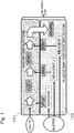
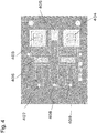
- Fig. 1 is a general conceptual view of a chip with micro-channel according to the present disclosure.
- the DNA chip with micro-channel for DNA analysis in the present disclosure has a structure in which a silicon layer 101 (chip A) and a plastic layer 102 (chip B) are laminated.
- the chip A includes at least two PCR reactors connected in series in a micro-channel, and at least one filter including a plurality of silicon pillars between the PCR reactors
- the chip B includes a reagent, a liquid delivery mechanism and a sensor in a micro-channel, and the reagent, liquid delivery mechanism and sensor can be changed according to a kind of an analyte and an object to be detected. Throw of an analyte and a reagent and treatments proceed in order along the arrow in Fig. 1 .
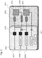
- Fig. 2 is a schematic view showing components of the DNA chip with micro-channel for DNA analysis according to the present disclosure.
- the material of the chip A is silicon, a channel and a structure are engraved on a silicon substrate by photolithography and RIE (reactive ion gas etching), a PCR 1: 203 and PCR 2: 204, and also a mixer 205 and a filter 206 are formed, and connection is established as in the figure.
- RIE reactive ion gas etching
- the material of the chip B is plastic, for example, PMMA (polymethylmethacrylate resin) or PDMS (polydimethylsiloxane) may be used. Further, an adhesive layer or elastomer may be used for a connection area with the silicon layer.
- reagents (1) and (2) such as a primer and polymerase which are used for reaction in the PCR reactors, and also a reagent (3) which is used in the sensor are arranged in the chip.
- the analyte is injected through a hole 207, and the reagents (1) and (2) are injected through holes 208 and 209, respectively.
- the reagent may be freeze-dried, and dissolved by pouring a buffer solution when used.
- the chip B has a liquid delivery mechanism, where a pump 210 and a valve 211 are arranged to provide a function of pouring the reagent into the chip and control the input of the reagent and timing.
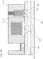
- Figs. 3A and 3B are sectional schematic views showing components of the DNA chip with micro-channel for DNA analysis according to the present disclosure.
- Fig. 3A is a sectional view including a reagent, a pump and a valve.
- a pump 310 and a valve 311 are embedded in a plastic section, and easily attached and detached.
- An actuator 312 of a driving section of the pump, for which a piezo element or a polymer actuator may be used, is arranged such that a membrane 313 can be moved up and down.
- a polymer actuator may be used.
- they are connected to a port and a channel formed of silicon of the lower surface, so that liquid delivery can be performed within the silicon layer.
- the micro-channel of the silicon layer is patterned from the lower surface by photolithography and RIE.
- a Pyrex glass 314 is used as a lid.
- the Pyrex glass 314 is bonded to the silicon surface using an anodic oxidation method.
- a through-hole is formed from the upper surface before the plastic layer is bonded.
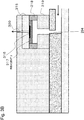
- Fig. 3B is sectional view of an area including a sensor.
- a sensor chip 315 is arranged such that a detection surface 316 faces downward.
- a sensor chip 317 is in a detachably attachable state.
- the detection surface may be dry-chemically treated with the reagent (3) and held in a cavity 318.
- a spacer 319 may be provided.
- An air hole 320 may be provided on the upper surface because degassing is necessary at the time of liquid delivery to the cavity of the sensor.
- Fig. 4 is a layout view of components included in a silicon chip used in the embodiment of the present disclosure.
- the thickness of the silicon substrate may range about 500 to 800 ⁇ m.
- the parts are etched from the upper surface and the lower surface using two masks.
- the peripheries of a PCR1: 403 and a PCR2: 404 are mostly etched from both the upper and lower surfaces by RIE to be completely hollowed out, so that the PCRs are thermally isolated.
- a channel, a mixer 405 and a micro-sieve 406 are formed by etching the lower surface to a depth of about 300 ⁇ m by RIE, and a Pyrex glass is anodic oxidation-bonded to cover the surface.
- Through-holes of connection areas between holes 407, 408 and 409 and the plastic section are formed by etching the upper surface to a depth of about 300 ⁇ m by RIE.
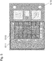
- Fig. 5 is a layout view of components included in a plastic chip of the present disclosure.
- a pump of a polymer actuator is mounted at the location of symbol 510, and a valve of the polymer actuator is mounted at the location of symbol 511.
- a sensor is connected at the location of symbol 515.
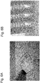
- Fig. 6A shows a photograph of a silicon chip section in a DNA chip with micro-channel for DNA analysis which is actually prepared in this embodiment.
- Fig. 6B shows a photograph of a filter section actually prepared by a method in this embodiment.
- Fig. 7 shows a photograph of a plastic chip and a silicon chip bonded thereto in a DNA chip with micro-channel for DNA analysis which is actually prepared in this embodiment.
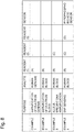
- Fig. 8 shows, in the form of a table, examples of using a DNA chip with micro-chip for DNA analysis in the present disclosure described in the embodiment for four kinds of purposes, respectively.
- the configurations of reagents will be described below.
- a desired DNA fraction including the 114th base of the 12th exon of an acetaldehyde dehydrogenase 2 (ALDH 2) gene was extracted and amplified from a human genome analyte by using a DNA chip with micro-channel for DNA analysis according to one embodiment of the present disclosure.
- a DNA fragment with a fraction length of 141 bp was extracted and amplified with the aforementioned Primer 1 and Primer 2 used as primers.
- the reagent (A) as a reagent 1 was mixed with an analyte in a mixer, and then reaction in a PCR 1 reactor was carried out in 30 cycles of PCR under conditions of 98°C for 30 seconds, 60°C for 30 seconds and 68°C for 30 seconds. Subsequently, the reaction product was made to pass through a filter and a PCR 2 as it was. Three ⁇ L of this sample was collected. Subsequently, existence or nonexistence of DNA amplification was checked using an electrophoresis method with agarose gel. The second lane in Fig. 9 corresponds to the result for existence or nonexistence of amplification of the DNA fragment collected from the sample. As shown in the second lane (L2) in Fig. 9 , it was confirmed that a desired DNA fragment (141 bp) was amplified.
- DNA was amplified from a blood analyte by using a DNA chip with micro-channel for DNA analysis according to one embodiment of the present disclosure.
- a DNA chip with micro-channel for DNA analysis As a model of DNA amplification, blood of each of types AB and O was used as a template.
- a DNA fragment including the 261st base of the sixth exon in a genome in human blood was extracted and amplified.
- a DNA fragment with a fraction length of 134 or 135 bp was extracted and amplified with the aforementioned Primer 3 and Primer 4 used as primers.
- the reagent (B) as a reagent 1 was mixed with an analyte in a mixer, and then reaction in a PCR 1 reactor was carried out in 35 cycles of PCR under conditions of 98°C for 30 seconds, 60°C for 30 seconds and 68°C for 30 seconds. Subsequently, the reaction product was made to pass through a filter, and unnecessary blood components fractioned in the PCR reactor were removed. The reaction product was made to pass through a PCR 2 reactor as it was, three ⁇ L of this sample solution was collected, and existence or nonexistence of DNA amplification was checked by electrophoresis. The second and third lanes in Fig.
- Allele-specific DNA was amplified from a blood analyte by using a DNA chip with micro-channel for DNA analysis according to one embodiment of the present disclosure.
- a DNA chip with micro-channel for DNA analysis As a model of allele-specific DNA amplification, blood of each of types AB and O was used as a template.
- the aforementioned Primer 3 and Primer 4 were used as primers for amplifying a DNA fragment including the 261st base (SNP site) of the sixth exon of a human genome.
- a measurement was performed using Primer 3' and Primer 4 as allele-specific primers for determining a difference in the 261st base (SNP site) of the sixth exon.
- the allele-specific primer produces an extension reaction specifically only with blood of type AB.
- the reagent (B) as a reagent 1 was mixed with an anaiyte in a mixer, and then reaction in a PCR 1 reactor was carried out in 35 cycles of PCR under conditions of 98°C for 30 seconds, 60°C for 30 seconds and 68°C for 30 seconds. Subsequently, impurities were removed with a micro-sieve, and reaction in a PCR reactor 2 was then carried out in 30 cycles of PCR under conditions of 95°C for 30 seconds, 60°C for 30 seconds and 72°C for 30 seconds with the reagent (C) used as a reagent (2). Three ⁇ L of this sample solution was collected, and existence or nonexistence of allele-specific DNA amplification was checked by electrophoresis.
- the second and third lanes in Fig. 11 correspond to the results for existence or nonexistence of amplification of the DNA fragments collected from the samples of types AB and O, respectively. It was confirmed that DNA was specifically amplified in only the sample of the type AB as shown in Fig. 11 .
- the reagent (B) as a reagent 1 was mixed with an analyte in a mixer, and then reaction in a PCR 1 reactor was carried out in 35 cycles of PCR under conditions of 98°C for 30 seconds, 60°C for 30 seconds and 68°C for 30 seconds. Subsequently, the reaction product was made to pass through a filter, freed of unnecessary blood components fractioned in the PCR reactor, and then mixed with a reagent 2 in a mixer 2, the mixture was introduced into a PCR reactor 2, and reaction in the PCR 2 reactor was carried out in 30 cycles of PCR under conditions of 95°C for 30 seconds, 60°C for 30 seconds and 72°C for 30 seconds with the reagent (C) used as the reagent 2.
- extraction and amplification of DNA or detection of a sequence of the DNA can be performed quickly and conveniently in a DNA chip with micro-channel for DNA analysis, and the chip can be used for a variety of applications, leading to enhancement of versatility. Contribution to personalized medicine can be expected.
Landscapes
- Chemical & Material Sciences (AREA)
- Health & Medical Sciences (AREA)
- Chemical Kinetics & Catalysis (AREA)
- Life Sciences & Earth Sciences (AREA)
- General Health & Medical Sciences (AREA)
- Organic Chemistry (AREA)
- Analytical Chemistry (AREA)
- Clinical Laboratory Science (AREA)
- Zoology (AREA)
- Proteomics, Peptides & Aminoacids (AREA)
- Engineering & Computer Science (AREA)
- Wood Science & Technology (AREA)
- Biochemistry (AREA)
- Molecular Biology (AREA)
- Hematology (AREA)
- Dispersion Chemistry (AREA)
- Biophysics (AREA)
- Microbiology (AREA)
- Immunology (AREA)
- Biotechnology (AREA)
- Physics & Mathematics (AREA)
- Bioinformatics & Cheminformatics (AREA)
- General Engineering & Computer Science (AREA)
- Genetics & Genomics (AREA)
- Apparatus Associated With Microorganisms And Enzymes (AREA)
- Measuring Or Testing Involving Enzymes Or Micro-Organisms (AREA)
Description
- The present disclosure relates to a chip with micro-channel which is formed on a laminated substrate of silicon and plastic. More particularly, the present disclosure relates to a chip with micro-channel which integrally has functionalities for quickly and conveniently extracting and amplifying desired DNA from an analyte containing a gene, or detecting a sequence of the DNA.
- In recent years, progress of genetic diversity analysis and expression analysis has been outstanding owing to improvement of DNA analysis techniques. Particularly in medical fields, the relationship between diseases and genes attracts attention. For example, by analyzing information of individual genetic information (specific DNA sequence) related to a disease, suitable treatment or administration can be carried out for each individual patient (personalized medicine). In personalized medicine, in situ diagnostics are most desirable, and speedy and convenient techniques with a strong aspect of POCT (Point of Care Testing) are desired. Therefore, it is strongly desired to realize a device capable of quickly and conveniently extracting and amplifying DNA of a gene to be analyzed from a collected analyte such as blood, and detecting a sequence of the DNA.
- As one of means to meet these requirements, micro-total analysis systems (µTAS) (also called as a lab-on-chip) have attracted attention in recent years. In the µTAS or lab-on-chip, micro-channels and ports having fine structures in a micrometer order are provided in a substrate, and various kinds of operations including mixing, extraction, refinement, chemical reaction and/or analysis of a substance, and so on can be performed within the structures. The µTAS has been partially put into practical use. Since various kinds of operations are performed within fine structures, the µTAS has the following features compared to the same type of device in common size: (1) the use amounts of a sample and a reagent are remarkably small; (2) the analysis time is short; (3) the sensitivity is high; (4) it can be carried to an actual spot to perform analysis on the spot; and (5) it is disposable. Structures prepared for the purpose described above and having fine structures such as micro-channels and ports in a substrate are collectively called as a chip with micro-channel or device with micro-fluid.
- For analyzing DNA in a gene in an analyte in a short time using a chip with micro-channel, it is necessary to incorporate functionalities of extraction and amplification into the chip, and realization of a fine filter for separating impurities such as blood cells and a PCR (polymerase chain reaction) capable of increasing and decreasing the temperature at a high speed is required. In addition, convenience in use is required, and it is therefore desirable to be able to stably retain an analyte, a reagent and the like in the chip. Further, in personalized medicine applications, it is desirable to have a configuration that allows treatment from blood, and to be able to sense a single base-multiple system (SNP) in DNA at a detection section. That is, it is desired to realize a versatile chip that can flexibly adapt to operating conditions.
- However, due to limitations on the nature of a material of a substrate that forms a chip with micro-channel, it is difficult to realize a device with micro-channel which can meet all the foregoing requirements. The reason for this will be described below.
- Plastic or silicon is used as a material of a substrate of a chip with micro-channel. The plastic substrate has such a feature that material costs are relatively low, it is easy to perform cutting processing, and affinity with a biological/bio material is relatively high, so that a reagent is easily retained, and so on. On the other hand, however, the plastic substrate has a problem that it is not suitable for formation of a fine filter structure for separating impurities such as blood cells and for formation of a thermal reactor for which it is required to increase and decrease the temperature at a high speed, such as a PCR (polymerase chain reaction), because it is difficult to process fine structures in a sub-micrometer order and the thermal conductivity of the material is not satisfactory. The silicon substrate is suitable for formation of a fine filter structure and a PCR thermal reactor because fine structures are easily formed by a semiconductor lithography technique and the thermal conductivity is higher by 2 to 3 order of magnitude than that of plastic. On the other hand, however, there is the problem that the unit price of the material is high in comparison with plastic, and the silicon substrate is not suitable for storage of a reagent because affinity between the surface of silicon and a biological/bio material is not necessarily high, and therefore non-specific adsorption of a protein and DNA occurs. As described above, plastic and silicon have mutually contradictory advantages and disadvantages, and with a configuration using a substrate of only one of silicon and plastic, conditions required for a chip with micro-channel for used in DNA analysis cannot be adequately satisfied.
- As means for solving the above-described problems, a chip with micro-channel has been proposed in which a silicon substrate and a plastic substrate are laminated (see, for example, BioMed Microdevice (2011), 13:19-27 and Proceeding of 43rd International Symposium on Microelectronics (IMAPS 2010), 000036).
- In BioMed Microdevice (2011), 13:19-27, a structure is disclosed in which plastic and silicon are laminated, and a chip with micro-channel and a liquid delivery section are arranged separately. In this method, however, the temperature cannot be increased and decreased at a high speed because a thermal reactor is formed of a plastic material, and also the reactor is isolated from silicon as a heating surface with a glass substrate interposed therebetween, so that it is very difficult to secure a thermal contact, leading to poor heat conduction. Further, the method cannot be used conveniently because it employs a structure in which an analyte and a reagent are supplied from outside the chip. Therefore, the method has the problem that it is not suitable for quick and convenient treatments.
- In Proceeding of 43rd International Symposium on Microelectronics (IMAPS 2010), 000036, a structure is disclosed in which a thermal reactor is formed in a silicon chip, and an analyte and a reagent are supplied from the inside of the chip. Therefore, increasing and decreasing of temperature at a high speed and convenient treatments can be achieved. However, in this method, a sensor is confined to a DNA micro-array chip, and this is formed on a silicon substrate identical to that of the thermal reactor (PCR). That is, steps of producing the thermal reactor and the sensor should be successively performed, and the design cannot be flexibly changed according to an intended purpose. Further, only one thermal reactor is mounted, and only a refined genome can be used as an analyte, so that a treatment from blood cannot be performed. The method cannot adapt to applications that require two stages of PCRs: a PCR intended for extracting a genome to be analyzed from blood and a PCR intended for selectively amplifying DNA based on presence/absence of a SNP in the object to be analyzed. Further, a filter for separating and removing blood-derived blood cells generated during the treatment is not present. That is, the method has the problem that it cannot adapt to applications of detection from blood, and is therefore poor in versatility.
- That is, the disclosed methods have the major problem that both a configuration of a high-performance chip with micro-channel which is necessary to perform DNA analysis quickly and conveniently and a configuration of a chip with micro-channel which has high versatility cannot be achieved.
- The present disclosure has been made for solving the problems described above. One non-limiting and exemplary embodiment provide a DNA chip with micro-channel for DNA analysis, which performs extraction/amplification of DNA or detection of a sequence of the DNA quickly and conveniently and which has high versatility.
- In one general aspect, the techniques disclosed here feature: a DNA chip with micro-channel for DNA analysis of DNA included in an analyte according to PCR method, the DNA chip includes:
- a first layer (101) made of silicon; and
- a second layer (102) made of plastic,
- wherein the second layer (102) is formed on the first layer (101), and the second layer (102) is configured to be changeably selected depending on a kind of the analyte and an object to be analyzed,
- the first layer (101) includes:
- at least four openings (291, 292, 293, 294);
- at least two PCR reactors (203, 204, 403, 404); and
- a micro channel connecting among the openings and the PCR reactors,
- the second layer (102) includes:
- a reagent (1, 2) to be used in the PCR method;
- a pump (312); and
- a sensor (315),
- the reagent (1, 2) overlaps at least one opening included the plurality of openings when one sees from normal direction of the first layer (101),
- the pump (312) overlaps at least two openings included the plurality of openings when one sees from normal direction of the first layer (101),
- the pump supplies the reagent to the PCR reactors via the micro channel such that mixture of the reagent and the analyte is supplied to the PCR reactors; and
- the mixture is transported to the sensor from the PCR reactors such that the sensor analyzes DNA included in the analyte according to PCR method.
- By providing the structure described above, a PCR capable of increasing and decreasing the temperature at a high speed can be incorporated, and an analyte and reagent can be manipulated and stored within the chip, so that DNA analysis can be performed quickly and conveniently. Also, PCR amplification and filtering with not only a genome but also blood can be performed by providing the above-described structure. Therefore, multiple (at least four) applications: (1) extraction and amplification of DNA from a genome, (2) extraction and amplification of DNA from blood, (3) extraction and amplification of allele-specific DNA from a genome or blood and (4) detection of a SNP from a genome or blood, etc. can be accommodated only by changing the configurations of a reagent, a liquid delivery mechanism and a sensor in a chip B with the configuration of a chip A unchanged. That is, a high versatility can be imparted to the chip.
- According to the present disclosure, extraction and amplification of DNA or detection of a sequence of the DNA can be performed quickly and conveniently in a DNA chip with micro-channel for DNA analysis, and the chip can be used for a variety of applications, leading to enhancement of versatility.
- Additional benefits and advantages of the disclosed embodiments will be apparent from the specification and figures. The benefits and/or advantages may be individually provided by the various embodiments and features of the specification and drawings disclosure, and need not all be provided in order to obtain one or more of the same.
- The present disclosure will become readily understood from the following description of non-limiting and exemplary embodiments thereof made with reference to the accompanying drawings, in which like parts are designated by like reference numeral and in which:
-
Fig. 1 is a general conceptual view of a DNA chip with micro-channel for DNA analysis according to the present disclosure; -
Fig. 2 is a schematic view showing components of the DNA chip with micro-channel for DNA analysis according to the present disclosure; -
Fig. 3A is a sectional schematic view showing the components of the DNA chip with micro-channel for DNA analysis according to the present disclosure, the sectional view including a reagent, a pump and a valve; -
Fig. 3B is a sectional schematic view showing the components of the DNA chip with micro-channel for DNA analysis according to the present disclosure, the sectional view including a sensor; -
Fig. 4 is a layout view of components included in a silicon chip of the present disclosure; -
Fig. 5 is a layout view of components included in a plastic chip of the present disclosure; -
Fig. 6A shows a silicon chip obtained using a method of the present disclosure, andFig. 6B shows a SEM photograph of a filter obtained using the method of the present disclosure; -
Fig. 7 is a plastic chip obtained using the method of the present disclosure, and a silicon chip bonded thereto; -
Fig. 8 is a table of examples, which shows versatility of the present disclosure; -
Fig. 9 shows a result of genetic analysis, which is obtained in example 1 of the present disclosure; -
Fig. 10 shows a result of genetic analysis, which is obtained in example 2 of the present disclosure; -
Fig. 11 shows a result of genetic analysis, which is obtained in example 3 of the present disclosure; and -
Fig. 12 shows a result of genetic analysis, which is obtained in example 4 of the present disclosure. - According to a first aspect of the present disclosure, a DNA chip with micro-channel for DNA analysis of DNA included in an analyte according to PCR method, the DNA chip includes:
- a first layer (101) made of silicon; and
- a second layer (102) made of plastic,
- wherein the second layer (102) is formed on the first layer (101), and the second layer (102) is configured to be changeably selected depending on a kind of the analyte and an object to be analyzed,
- the first layer (101) includes:
- at least four openings (291, 292, 293, 294);
- at least two PCR reactors (203, 204, 403, 404);
- at least one filter (206) provided between PCR reactors; and
- a micro channel connecting among the openings, the PCR reactors, and the at least one filter,
- the second layer (102) includes:
- a reagent (1, 2) to be used in the PCR method;
- a pump (312); and
- a sensor (315),
- the reagent (1, 2) overlaps at least one opening (291) included in the four openings when one sees from normal direction of the first layer (101),
- the pump (312) overlaps at least two openings (292, 293) included in the four openings when one sees from normal direction of the first layer (101),
- the pump supplies the reagent to the PCR reactors via the micro channel such that mixture of the reagent and the analyte is supplied to the PCR reactors; and
- the mixture is transported from the PCR reactor to the sensor via at least one opening (294) included in the four openings such that the sensor analyzes DNA included in the analyte.
- A DNA chip with micro-channel for DNA analysis according to a second aspect is the chip with micro-channel for DNA analysis according to the first aspect, wherein a peripheral area made of silicon around the PCR reactor may be hollowed out except for an area connected to the micro channel.
- When the outer peripheral area of the PCR reactor is mostly hollowed out as described above to thermally isolate the peripheral area, release of heat to the outer peripheral area and absorption of heat from the outer peripheral area can be suppressed, and therefore a PCR capable of increasing and decreasing the temperature at a higher speed can be achieved, so that DNA analysis can be performed more quickly.
- A DNA chip with micro-channel for DNA analysis according to a third aspect is the chip with micro-channel for DNA analysis according to the first aspect, wherein the filter may include a plurality of column pillars made of silicon formed by etching, a space between column pillars ranging from 1 micrometer to 10 micrometers.
- When the space between pillars ranges from 1 micrometer to 10 micrometers as described above, unnecessary blood cell components fragmented by the PCR reactor can be efficiently removed with a filter without causing the filter to be clogged upon blood being used as an analyte.
- A DNA chip with micro-channel for DNA analysis according to a fourth aspect is the chip with micro-channel for DNA analysis according to the first aspect, wherein a polymer actuator may be used as the liquid delivery mechanism.
- When a polymer actuator is used as a liquid delivery mechanism (e.g. pump), a high generative force is obtained for delivering a liquid, and therefore a filter is hard to be clogged with analyte-derived substances. Further, when a polymer actuator is used as a liquid delivery mechanism (e.g. valve), a high pressure resistance is obtained for stopping liquid delivery, and therefore leakage to a channel can be suppressed. Consequently, stable chip operations can be performed.
- A DNA analysis method of DNA included in an analyte according to PCR method according to a fifth aspect is a DNA analysis method of DNA included in an analyte according to PCR method, including:
- (a) providing a first layer (101) made of silicon and a plurality of second layers (102) made of plastic,
the first layer (101) including:- at least four openings (291, 292, 293, 294);
- at least two PCR reactors (203, 204, 403, 404);
- at least one filter (206) provided between PCR reactors; and
- a micro channel connecting among the openings, the PCR reactors, and the filter,
- a reagent (1, 2) to be used in the PCR method;
- a pump (312); and
- a sensor (315),
- (b) selecting one of the second layers (102) depending on a kind of the analyte and an object to be analyzed from the plurality of second layers (102),
- (c) forming the second layer selected in (b) on the first layer (101) to obtain a DNA chip with micro-channel,
wherein the reagent (1, 2) overlaps at least one opening (291) included in the four openings when one sees from normal direction of the first layer (101), and
the pump (312) overlaps at least two openings (292, 293) included in the four openings when one sees from normal direction of the first layer (101), - (d) supplying the analyte to an inside of the DNA chip with micro-channel;
- (e) supplying the reagent to the PCR reactors via the micro channel by using the pump such that mixtures of the reagent and the analyte are supplied to the PCR reactors;
- (f) performing PCR method to obtain PCR products in the PCR reactor;
- (g) transporting the PCR products obtained in (f) from the PCR reactor to the sensor via at least one opening (294) included in the four openings; and
- (h) detecting the PCR products by using the sensor to analyze DNA included in the analyte.
- A DNA analysis method of DNA included in an analyte according to PCR method by using a DNA chip with a micro-channel according to a sixth aspect is a DNA analysis method of DNA included in an analyte according to PCR method by using a DNA chip with a micro-channel, including:
- (a') providing a DNA chip with micro-channel;
the DNA chip including:- a first layer (101) made of silicon; and
- a second layer (102) made of plastic,
- wherein the second layer (102) is formed on the first layer (101),
- the first layer (101) includes:
- at least four openings (291, 292, 293, 294);
- at least two PCR reactors (203, 204, 403, 404);
- at least one filter (206) provided between PCR reactors; and
- a micro channel connecting among the openings, the PCR reactors, and the at least one filter,
- the second layer (102) includes:
- a reagent (1, 2) to be used in the PCR method;
- a pump (312); and
- a sensor (315),
- wherein the reagent (1, 2) overlaps at least one opening (291) included in the four openings when one sees from normal direction of the first layer (101), and
- the pump (312) overlaps at least one opening (292, 293) included in the four openings when one sees from normal direction of the first layer (101),
- (d) supplying the analyte to an inside of the DNA chip with micro-channel for DNA analysis;
- (e) supplying the reagent to the PCR reactors via the micro channel by using the pump such that mixtures of the reagent and the analyte are supplied to the PCR reactors;
- (f) performing PCR method to obtain PCR products in the PCR reactor;
- (g) transporting the PCR products obtained in (f) from the PCR reactor to the sensor via at least one opening (294) included in the four openings; and
- (h) detecting the PCR products by using the sensor to analyze DNA included in the analyte.
- Embodiments of the present disclosure will be described below with reference to the drawings.
-
Fig. 1 is a general conceptual view of a chip with micro-channel according to the present disclosure. The DNA chip with micro-channel for DNA analysis in the present disclosure has a structure in which a silicon layer 101 (chip A) and a plastic layer 102 (chip B) are laminated. The chip A includes at least two PCR reactors connected in series in a micro-channel, and at least one filter including a plurality of silicon pillars between the PCR reactors, the chip B includes a reagent, a liquid delivery mechanism and a sensor in a micro-channel, and the reagent, liquid delivery mechanism and sensor can be changed according to a kind of an analyte and an object to be detected. Throw of an analyte and a reagent and treatments proceed in order along the arrow inFig. 1 . -
Fig. 2 is a schematic view showing components of the DNA chip with micro-channel for DNA analysis according to the present disclosure. The material of the chip A is silicon, a channel and a structure are engraved on a silicon substrate by photolithography and RIE (reactive ion gas etching), a PCR 1: 203 and PCR 2: 204, and also amixer 205 and afilter 206 are formed, and connection is established as in the figure. - The material of the chip B is plastic, for example, PMMA (polymethylmethacrylate resin) or PDMS (polydimethylsiloxane) may be used. Further, an adhesive layer or elastomer may be used for a connection area with the silicon layer. As the reagent, reagents (1) and (2) such as a primer and polymerase which are used for reaction in the PCR reactors, and also a reagent (3) which is used in the sensor are arranged in the chip. The analyte is injected through a
hole 207, and the reagents (1) and (2) are injected throughholes pump 210 and avalve 211 are arranged to provide a function of pouring the reagent into the chip and control the input of the reagent and timing. -
Figs. 3A and3B are sectional schematic views showing components of the DNA chip with micro-channel for DNA analysis according to the present disclosure. -
Fig. 3A is a sectional view including a reagent, a pump and a valve. A pump 310 and a valve 311 are embedded in a plastic section, and easily attached and detached. Anactuator 312 of a driving section of the pump, for which a piezo element or a polymer actuator may be used, is arranged such that amembrane 313 can be moved up and down. Given that the chip is disposable, for example, a polymer actuator may be used. As shown in the figure, they are connected to a port and a channel formed of silicon of the lower surface, so that liquid delivery can be performed within the silicon layer. The micro-channel of the silicon layer is patterned from the lower surface by photolithography and RIE. For tightly closing the patterned channel, a Pyrex glass 314 is used as a lid. The Pyrex glass 314 is bonded to the silicon surface using an anodic oxidation method. For connecting micro-channels of plastic and silicon, a through-hole is formed from the upper surface before the plastic layer is bonded. -
Fig. 3B is sectional view of an area including a sensor. Asensor chip 315 is arranged such that adetection surface 316 faces downward. For example, asensor chip 317 is in a detachably attachable state. Further, the detection surface may be dry-chemically treated with the reagent (3) and held in acavity 318. When the distance between the sensor chip and the silicon chip is long, aspacer 319 may be provided. Anair hole 320 may be provided on the upper surface because degassing is necessary at the time of liquid delivery to the cavity of the sensor. -
Fig. 4 is a layout view of components included in a silicon chip used in the embodiment of the present disclosure. - The thickness of the silicon substrate, for example, may range about 500 to 800µm. The parts are etched from the upper surface and the lower surface using two masks. The peripheries of a PCR1: 403 and a PCR2: 404 are mostly etched from both the upper and lower surfaces by RIE to be completely hollowed out, so that the PCRs are thermally isolated. On the other hand, a channel, a
mixer 405 and a micro-sieve 406 are formed by etching the lower surface to a depth of about 300µm by RIE, and a Pyrex glass is anodic oxidation-bonded to cover the surface. Through-holes of connection areas betweenholes -
Fig. 5 is a layout view of components included in a plastic chip of the present disclosure. A pump of a polymer actuator is mounted at the location ofsymbol 510, and a valve of the polymer actuator is mounted at the location ofsymbol 511. A sensor is connected at the location ofsymbol 515. -
Fig. 6A shows a photograph of a silicon chip section in a DNA chip with micro-channel for DNA analysis which is actually prepared in this embodiment. As one example of processing,Fig. 6B shows a photograph of a filter section actually prepared by a method in this embodiment. -
Fig. 7 shows a photograph of a plastic chip and a silicon chip bonded thereto in a DNA chip with micro-channel for DNA analysis which is actually prepared in this embodiment. -
Fig. 8 shows, in the form of a table, examples of using a DNA chip with micro-chip for DNA analysis in the present disclosure described in the embodiment for four kinds of purposes, respectively. The configurations of reagents will be described below. - (A) Taq-polymerase manufactured by TAKARA BIO INC.: 0.2µL, PCR mix: 3µL, water: 2µL, 2mMdNTP: 1µL, 10µM Primer 1: 1µL, 10µM Primer 2: 1µL (sequences of the primers are described in *).
- (B) KOD-FX-polymerase manufactured by TOYOBO CO., LTD: 0.2µL, 2 × KOD-Buffer: 5µL, 2mMdNTP: 1µL, 10µM Primer 3: 1µL, 10µM Primer 4: 1µL (sequences of the primers are described in *).
- (C) Taq-polymerase manufactured by TAKARA BIO INC.: 0.2µL, PCR mix: 3µL, Primer 3': 2µL, Primer 4: 2µL, distilled water 10.8µL (sequences of the primers are described in *).
- (D) Tricine buffer solution (pH 8.8) 1.8µL 45mM
oxidized nicotinamide dinucleotide 0.2µL 1 mM
magnesium chloride 0.4µL 1.7mM
potassium ferricyanide 2µL 10mM
glyceraldehyde 3-phosphate 0.66µL 10mM
diaphorase 1µL 10 U/mL
glyceraldehyde 3-phosphate dehydrogenase 1µL 32 U/mL
pyrophosphatase 0.5µL 5U/mL - Examples showing versatility of the DNA chip with micro-channel for DNA analysis in the present disclosure will be described in detail below. The present disclosure is not limited by the following examples.
- A desired DNA fraction including the 114th base of the 12th exon of an acetaldehyde dehydrogenase 2 (ALDH 2) gene was extracted and amplified from a human genome analyte by using a DNA chip with micro-channel for DNA analysis according to one embodiment of the present disclosure. A DNA fragment with a fraction length of 141 bp was extracted and amplified with the
aforementioned Primer 1 andPrimer 2 used as primers. - The reagent (A) as a
reagent 1 was mixed with an analyte in a mixer, and then reaction in aPCR 1 reactor was carried out in 30 cycles of PCR under conditions of 98°C for 30 seconds, 60°C for 30 seconds and 68°C for 30 seconds. Subsequently, the reaction product was made to pass through a filter and aPCR 2 as it was. Three µL of this sample was collected. Subsequently, existence or nonexistence of DNA amplification was checked using an electrophoresis method with agarose gel. The second lane inFig. 9 corresponds to the result for existence or nonexistence of amplification of the DNA fragment collected from the sample. As shown in the second lane (L2) inFig. 9 , it was confirmed that a desired DNA fragment (141 bp) was amplified. - DNA was amplified from a blood analyte by using a DNA chip with micro-channel for DNA analysis according to one embodiment of the present disclosure. As a model of DNA amplification, blood of each of types AB and O was used as a template. A DNA fragment including the 261st base of the sixth exon in a genome in human blood was extracted and amplified. A DNA fragment with a fraction length of 134 or 135 bp was extracted and amplified with the
aforementioned Primer 3 andPrimer 4 used as primers. - The reagent (B) as a
reagent 1 was mixed with an analyte in a mixer, and then reaction in aPCR 1 reactor was carried out in 35 cycles of PCR under conditions of 98°C for 30 seconds, 60°C for 30 seconds and 68°C for 30 seconds. Subsequently, the reaction product was made to pass through a filter, and unnecessary blood components fractioned in the PCR reactor were removed. The reaction product was made to pass through aPCR 2 reactor as it was, three µL of this sample solution was collected, and existence or nonexistence of DNA amplification was checked by electrophoresis. The second and third lanes inFig. 10 correspond to the results for existence or nonexistence of amplification of the DNA fragments collected from the samples of types AB and O, respectively. It was confirmed that DNA was amplified in each of the samples of AB (135bp) and O (134bp) as shown inFig. 10 . - Allele-specific DNA was amplified from a blood analyte by using a DNA chip with micro-channel for DNA analysis according to one embodiment of the present disclosure. As a model of allele-specific DNA amplification, blood of each of types AB and O was used as a template. The
aforementioned Primer 3 andPrimer 4 were used as primers for amplifying a DNA fragment including the 261st base (SNP site) of the sixth exon of a human genome. A measurement was performed using Primer 3' andPrimer 4 as allele-specific primers for determining a difference in the 261st base (SNP site) of the sixth exon. The allele-specific primer produces an extension reaction specifically only with blood of type AB. - The reagent (B) as a
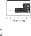
reagent 1 was mixed with an anaiyte in a mixer, and then reaction in aPCR 1 reactor was carried out in 35 cycles of PCR under conditions of 98°C for 30 seconds, 60°C for 30 seconds and 68°C for 30 seconds. Subsequently, impurities were removed with a micro-sieve, and reaction in aPCR reactor 2 was then carried out in 30 cycles of PCR under conditions of 95°C for 30 seconds, 60°C for 30 seconds and 72°C for 30 seconds with the reagent (C) used as a reagent (2). Three µL of this sample solution was collected, and existence or nonexistence of allele-specific DNA amplification was checked by electrophoresis. The second and third lanes inFig. 11 correspond to the results for existence or nonexistence of amplification of the DNA fragments collected from the samples of types AB and O, respectively. It was confirmed that DNA was specifically amplified in only the sample of the type AB as shown inFig. 11 . - An example of detecting a SNP from a blood analyte by using a DNA chip with micro-channel for DNA analysis according to one embodiment of the present disclosure is described.
- As a model of SNP detection, blood of each of types AB and O was used as a template as in the case of example 3. The types of primers are same as those in example 3.
- The reagent (B) as a
reagent 1 was mixed with an analyte in a mixer, and then reaction in aPCR 1 reactor was carried out in 35 cycles of PCR under conditions of 98°C for 30 seconds, 60°C for 30 seconds and 68°C for 30 seconds. Subsequently, the reaction product was made to pass through a filter, freed of unnecessary blood components fractioned in the PCR reactor, and then mixed with areagent 2 in amixer 2, the mixture was introduced into aPCR reactor 2, and reaction in thePCR 2 reactor was carried out in 30 cycles of PCR under conditions of 95°C for 30 seconds, 60°C for 30 seconds and 72°C for 30 seconds with the reagent (C) used as thereagent 2. Only 1µL of this sample solution was delivered to a pyrophosphoric acid sensor, and mixed with a dried reagent (D), and a voltage of 600 mV was applied to a working electrode to measure a voltage value. It was confirmed that since pyrophosphoric acid was generated as a by-product only when allele-specific DNA amplification occurred, a significant difference in current was observed between the types AB and O, so that a SNP could be detected as shown inFig. 12 . - According to the present disclosure, extraction and amplification of DNA or detection of a sequence of the DNA can be performed quickly and conveniently in a DNA chip with micro-channel for DNA analysis, and the chip can be used for a variety of applications, leading to enhancement of versatility. Contribution to personalized medicine can be expected.
-
- 101 Silicon substrate
- 102 Plastic substrate
- 203 PCR (1)
- 204 PCR (2)
- 205 Mixer
- 206 Filter
- 207 Through hole (analyte)
- 208 Through hole (reagent (1))
- 209 Through hole (reagent (2))
- 210, 310 Pump
- 211, 311 Valve
- 312 Actuator
- 313 Membrane
- 314 Pyrex glass
- 315 Sensor chip
- 316 Detection surface
- 317 Reagent (3)
- 318 Cavity
- 319 Spacer
- 320 Air hole
-
- <110> Panasonic Corporation
<120> DNA CHIP WITH MICRO-CHANNEL FOR DNA ANALYSIS
<130> P642289E0
<160> 5
<210> 1
<211> 20
<212> DNA
<213> Artificial Sequence
<220>
<223> primer
<400> 1
acgggctgca ggcatacact 20 - <210> 2
<211> 17
<212> DNA
<213> Artificial Sequence
<220>
<223> primer
<400> 2
ggc agg tcc tga acc tc 17 - <210> 3
<211> 17
<212> DNA
<213> Artificial sequence
<220>
<223> primer
<400> 3
taggaaggat gtcctcg 17 - <210> 4
<211> 22
<212> DNA
<213> Artificial Sequence
<220>
<223> primer
<400> 4
taggaaggat gtcctcgtga cg 22 - <210> 5
<211> 24
<212> DNA
<213> Artificial Sequence
<220>
<223> primer
<400> 5
ttcttgatgg caaacacagt taac 24
Claims (6)
- A DNA chip with micro-channel for DNA analysis of DNA included in an analyte according to PCR method, the DNA chip comprising:a first layer (101) made of silicon; anda second layer (102) made of plastic,wherein the second layer (102) is formed on the first layer (101), and the second layer (102) is configured to be changeably selected depending on a kind of the analyte and DNA,the first layer (101) includes:at least four openings (291, 292, 293, 294);at least two PCR reactors (203, 204, 403, 404);at least one filter (206) provided between PCR reactors; anda micro channel connecting among the openings, the PCR reactors, and the filter,the second layer (102) includes:a pump (312); anda sensor (315),wherein a reagent (1, 2) is provided to overlap at least one opening (291) of the four openings when one sees from normal direction of the first layer (101),the pump (312) overlaps at least two openings (292, 293) of the four openings when one sees from normal direction of the first layer,the pump supplies the reagent to the PCR reactors via the micro channel such that mixture of the reagent and the analyte is supplied to the PCR reactors,the mixture is transported to the sensor via at least one opening (294) included in the four openings such that the sensor analyzes DNA included in the analyte.
- The DNA chip according to claim 1, wherein a peripheral area made of silicon around the PCR reactor is hollowed out except for an area connected to the micro channel.
- The DNA chip according to claim 1, wherein the filter comprises a plurality of column pillars made of silicon formed by etching, a space between column pillars ranging from 1 micro-meters to 10 micro-meters.
- The DNA chip according to claim 1, wherein a polymer actuator is used as a pump.
- DNA analysis method of DNA included in a analyte according to PCR method, the method comprising:(a) providing a first layer (101) made of silicon and a plurality of second layers (102) made of plastic,
the first layer (101) including:at least four openings (291, 292, 293, 294);at least two PCR reactors (203, 204, 403, 404);at least one filter (206) provided between PCR reactors; anda micro channel interconnecting the openings, the PCR reactors, and the filter,each second layer (102) including:a reagent (1, 2);a pump (312); anda sensor (315),(b) selecting one of the second layer (102) depending on a kind of the analyte and DNA,(c) forming the selected second layer on the first layer (101) to obtain a DNA chip with micro channel, wherein the reagent (1, 2) overlaps at least one opening (291) included in the four openings when one sees from normal direction of the first layer (101), the pump (312) overlaps at least two openings (292, 293) included in the four openings when one sees from normal direction of the first layer (101),(d) supplying the analyte to the PCR reactors;(e) supplying the reagent to the PCR reactors via the micro channel by using the pump such that mixtures of the reagent and the analyte are supplied to the PCR reactors;(f) performing PCR method to obtain PCR products;(g) transporting the PCR products to the sensor via at least one opening (294) included in the four openings; and(h) detecting the PCR products by using the sensor to analyze DNA included in the analyte. - DNA analysis method of DNA included in an analyte according to PCR method by using a DNA chip with a micro-channel, the method comprising:(a') providing a DNA chip with a micro-channel;
the DNA chip including:a first layer (101) made of silicon; anda second layer (102) made of plastic,wherein the second layer (102) is formed on the first layer (101),the first layer (101) includes:at least four openings (291, 292, 293, 294);at least two PCR reactors (203, 204, 403, 404);at least one filter (206) provided between PCR reactors; anda micro channel connecting among the openings, the PCR reactors, and the filter,the second layer (102) includes:a reagent (1, 2);a pump (312); anda sensor (315),wherein the reagent (1, 2) overlaps at least one opening (291) included in the four openings when one sees from normal direction of the first layer,the pump (312) overlaps at least two openings (292, 293) included in the four openings when one sees from normal direction of the first layer (101),(d) supplying the analyte to the PCR reactors;(e) supplying the reagent to the PCR reactors via the micro channel by using the pump such that mixtures of the reagent and the analyte are supplied to the PCR reactors;(f) performing PCR method to obtain PCR products;(g) transporting the PCR products to the sensor via at least one opening (294) included in the four openings; and(h) detecting the PCR products by using the sensor to analyze DNA included in the analyte.
Applications Claiming Priority (2)
| Application Number | Priority Date | Filing Date | Title |
|---|---|---|---|
| JP2012096885 | 2012-04-20 | ||
| PCT/JP2013/062310 WO2013157667A1 (en) | 2012-04-20 | 2013-04-19 | Dna analysis micro-channel chip |
Publications (3)
| Publication Number | Publication Date |
|---|---|
| EP2840129A1 EP2840129A1 (en) | 2015-02-25 |
| EP2840129A4 EP2840129A4 (en) | 2015-12-30 |
| EP2840129B1 true EP2840129B1 (en) | 2017-07-05 |
Family
ID=49383605
Family Applications (1)
| Application Number | Title | Priority Date | Filing Date |
|---|---|---|---|
| EP13778172.0A Active EP2840129B1 (en) | 2012-04-20 | 2013-04-19 | Dna chip with micro-channel for dna analysis |
Country Status (4)
| Country | Link |
|---|---|
| US (1) | US10100352B2 (en) |
| EP (1) | EP2840129B1 (en) |
| JP (1) | JP5583290B2 (en) |
| WO (1) | WO2013157667A1 (en) |
Families Citing this family (8)
| Publication number | Priority date | Publication date | Assignee | Title |
|---|---|---|---|---|
| CN106195321B (en) | 2016-08-30 | 2017-09-22 | 博奥颐和健康科学技术(北京)有限公司 | A kind of liquid storage and release component and liquid storage and release chip |
| CN109844111A (en) * | 2016-12-13 | 2019-06-04 | 荣研化学株式会社 | Microchip |
| CN106701556B (en) * | 2017-01-06 | 2019-02-12 | 广东顺德永诺生物科技有限公司 | Digital pcr detection device and its liquid channel system |
| WO2019203727A1 (en) * | 2018-04-19 | 2019-10-24 | Nanyang Technological University | Microfluidic board and method of forming the same |
| CN110849868B (en) * | 2019-10-21 | 2022-09-13 | 江苏大学 | Intelligent detection device and method for potassium bromate in flour based on micro-fluidic chip |
| CN110791422B (en) * | 2019-11-08 | 2021-07-20 | 宁波胤瑞生物医学仪器有限责任公司 | Regulating and controlling method of nucleic acid amplification instrument |
| EP4060017B1 (en) * | 2019-11-13 | 2024-01-17 | BOE Technology Group Co., Ltd. | Assay chip |
| US20230302448A1 (en) * | 2020-08-11 | 2023-09-28 | Kyorin Pharmaceutical Co., Ltd. | Nucleic acid amplification chip |
Family Cites Families (7)
| Publication number | Priority date | Publication date | Assignee | Title |
|---|---|---|---|---|
| AU2003284055A1 (en) * | 2002-10-09 | 2004-05-04 | The Board Of Trustees Of The University Of Illinois | Microfluidic systems and components |
| US20050142565A1 (en) * | 2003-12-30 | 2005-06-30 | Agency For Science, Technology And Research | Nucleic acid purification chip |
| CA2559778C (en) * | 2004-03-26 | 2011-07-05 | Infectio Recherche Inc. | Removable microfluidic flow cell |
| KR100773563B1 (en) * | 2006-11-14 | 2007-11-07 | 삼성전자주식회사 | Micro fluidics device with micro fluid treating element and method for fabricating the same |
| US20090227476A1 (en) * | 2008-03-07 | 2009-09-10 | Applied Microarrays, Inc. | Amplification and microarray detection apparatus and methods of making |
| FI20085299A0 (en) * | 2008-04-10 | 2008-04-10 | Valtion Teknillinen | Microfluidic chip devices and their use |
| EP2572788B1 (en) * | 2011-09-23 | 2015-03-18 | Imec | Method and device for thermal insulation of micro-reactors |
-
2013
- 2013-04-19 WO PCT/JP2013/062310 patent/WO2013157667A1/en active Application Filing
- 2013-04-19 JP JP2013557966A patent/JP5583290B2/en not_active Expired - Fee Related
- 2013-04-19 EP EP13778172.0A patent/EP2840129B1/en active Active
-
2014
- 2014-03-04 US US14/196,293 patent/US10100352B2/en active Active
Also Published As
| Publication number | Publication date |
|---|---|
| EP2840129A4 (en) | 2015-12-30 |
| US20140186846A1 (en) | 2014-07-03 |
| WO2013157667A1 (en) | 2013-10-24 |
| JPWO2013157667A1 (en) | 2015-12-21 |
| EP2840129A1 (en) | 2015-02-25 |
| JP5583290B2 (en) | 2014-09-03 |
| US10100352B2 (en) | 2018-10-16 |
Similar Documents
| Publication | Publication Date | Title |
|---|---|---|
| EP2840129B1 (en) | Dna chip with micro-channel for dna analysis | |
| US20240043893A1 (en) | Barcoding systems and methods for gene sequencing and other applications | |
| Zhu et al. | The vision of point-of-care PCR tests for the COVID-19 pandemic and beyond | |
| US8895292B2 (en) | Microfluidic chip devices and their use | |
| CN101990516B (en) | Multiplex sample preparation system and the use in integrated analysis system thereof | |
| EP3132037B1 (en) | Methods and systems for droplet tagging and amplification | |
| WO2018031691A1 (en) | Combined multiple-displacement amplification and pcr in an emulsion microdroplet | |
| Ouyang et al. | Pressure-modulated selective electrokinetic trapping for direct enrichment, purification, and detection of nucleic acids in human serum | |
| Yu et al. | 3-D microarrays biochip for DNA amplification in polydimethylsiloxane (PDMS) elastomer | |
| EP2280905A1 (en) | Multilevel microfluidic systems and methods | |
| US20080166770A1 (en) | Method and apparatus for amplifying and synthesisizing nucleic acid with denaturant | |
| Yin et al. | Digital Recombinase Polymerase Amplification, Digital Loop‐Mediated Isothermal Amplification, and Digital CRISPR‐Cas Assisted Assay: Current Status, Challenges, and Perspectives | |
| WO2014065758A1 (en) | A method of isolating nucleic acids in an aqueous sample using microfluidic device | |
| EP2840130B1 (en) | Dna chip with micro-channel for dna analysis | |
| Pham et al. | Fabrication of 3D continuous-flow reverse-transcription polymerase chain reaction microdevice integrated with on-chip fluorescence detection for semi-quantitative assessment of gene expression | |
| Jakaratanopas et al. | Integrated microfluidic systems for genetic analysis | |
| Becker et al. | Continuous-flow PCR using segmented flow and integrating sample preparation | |
| US20130096035A1 (en) | Self-sustained fluidic droplet cassette and system for biochemical assays | |
| Münchow et al. | Nucleic acid amplification in microsystems | |
| Chen | Fully integrated microsystem for bacterial genotyping | |
| Chabert | Gene Expression Analysis on Microchips |
Legal Events
| Date | Code | Title | Description |
|---|---|---|---|
| PUAI | Public reference made under article 153(3) epc to a published international application that has entered the european phase |
Free format text: ORIGINAL CODE: 0009012 |
|
| 17P | Request for examination filed |
Effective date: 20141120 |
|
| AK | Designated contracting states |
Kind code of ref document: A1 Designated state(s): AL AT BE BG CH CY CZ DE DK EE ES FI FR GB GR HR HU IE IS IT LI LT LU LV MC MK MT NL NO PL PT RO RS SE SI SK SM TR |
|
| AX | Request for extension of the european patent |
Extension state: BA ME |
|
| RAP1 | Party data changed (applicant data changed or rights of an application transferred) |
Owner name: IMEC VZW Owner name: PANASONIC CORPORATION |
|
| DAX | Request for extension of the european patent (deleted) | ||
| RA4 | Supplementary search report drawn up and despatched (corrected) |
Effective date: 20151126 |
|
| RIC1 | Information provided on ipc code assigned before grant |
Ipc: C12M 1/00 20060101AFI20160218BHEP Ipc: G01N 37/00 20060101ALI20160218BHEP Ipc: C12Q 1/68 20060101ALI20160218BHEP Ipc: C12N 15/09 20060101ALI20160218BHEP Ipc: B01L 7/00 20060101ALI20160218BHEP |
|
| GRAJ | Information related to disapproval of communication of intention to grant by the applicant or resumption of examination proceedings by the epo deleted |
Free format text: ORIGINAL CODE: EPIDOSDIGR1 |
|
| GRAP | Despatch of communication of intention to grant a patent |
Free format text: ORIGINAL CODE: EPIDOSNIGR1 |
|
| RIC1 | Information provided on ipc code assigned before grant |
Ipc: B01L 3/00 20060101ALI20161110BHEP Ipc: B01L 7/00 20060101ALI20161110BHEP Ipc: C12Q 1/68 20060101ALI20161110BHEP Ipc: G01N 37/00 20060101ALI20161110BHEP Ipc: C12N 15/09 20060101ALI20161110BHEP Ipc: C12M 1/00 20060101AFI20161110BHEP |
|
| GRAP | Despatch of communication of intention to grant a patent |
Free format text: ORIGINAL CODE: EPIDOSNIGR1 |
|
| INTG | Intention to grant announced |
Effective date: 20170105 |
|
| GRAS | Grant fee paid |
Free format text: ORIGINAL CODE: EPIDOSNIGR3 |
|
| GRAA | (expected) grant |
Free format text: ORIGINAL CODE: 0009210 |
|
| AK | Designated contracting states |
Kind code of ref document: B1 Designated state(s): AL AT BE BG CH CY CZ DE DK EE ES FI FR GB GR HR HU IE IS IT LI LT LU LV MC MK MT NL NO PL PT RO RS SE SI SK SM TR |
|
| REG | Reference to a national code |
Ref country code: GB Ref legal event code: FG4D |
|
| REG | Reference to a national code |
Ref country code: CH Ref legal event code: EP |
|
| REG | Reference to a national code |
Ref country code: AT Ref legal event code: REF Ref document number: 906620 Country of ref document: AT Kind code of ref document: T Effective date: 20170715 |
|
| REG | Reference to a national code |
Ref country code: IE Ref legal event code: FG4D |
|
| REG | Reference to a national code |
Ref country code: DE Ref legal event code: R096 Ref document number: 602013023160 Country of ref document: DE |
|
| REG | Reference to a national code |
Ref country code: NL Ref legal event code: MP Effective date: 20170705 |
|
| REG | Reference to a national code |
Ref country code: AT Ref legal event code: MK05 Ref document number: 906620 Country of ref document: AT Kind code of ref document: T Effective date: 20170705 |
|
| REG | Reference to a national code |
Ref country code: LT Ref legal event code: MG4D |
|
| PG25 | Lapsed in a contracting state [announced via postgrant information from national office to epo] |
Ref country code: HR Free format text: LAPSE BECAUSE OF FAILURE TO SUBMIT A TRANSLATION OF THE DESCRIPTION OR TO PAY THE FEE WITHIN THE PRESCRIBED TIME-LIMIT Effective date: 20170705 Ref country code: NL Free format text: LAPSE BECAUSE OF FAILURE TO SUBMIT A TRANSLATION OF THE DESCRIPTION OR TO PAY THE FEE WITHIN THE PRESCRIBED TIME-LIMIT Effective date: 20170705 Ref country code: SE Free format text: LAPSE BECAUSE OF FAILURE TO SUBMIT A TRANSLATION OF THE DESCRIPTION OR TO PAY THE FEE WITHIN THE PRESCRIBED TIME-LIMIT Effective date: 20170705 Ref country code: FI Free format text: LAPSE BECAUSE OF FAILURE TO SUBMIT A TRANSLATION OF THE DESCRIPTION OR TO PAY THE FEE WITHIN THE PRESCRIBED TIME-LIMIT Effective date: 20170705 Ref country code: NO Free format text: LAPSE BECAUSE OF FAILURE TO SUBMIT A TRANSLATION OF THE DESCRIPTION OR TO PAY THE FEE WITHIN THE PRESCRIBED TIME-LIMIT Effective date: 20171005 Ref country code: AT Free format text: LAPSE BECAUSE OF FAILURE TO SUBMIT A TRANSLATION OF THE DESCRIPTION OR TO PAY THE FEE WITHIN THE PRESCRIBED TIME-LIMIT Effective date: 20170705 Ref country code: LT Free format text: LAPSE BECAUSE OF FAILURE TO SUBMIT A TRANSLATION OF THE DESCRIPTION OR TO PAY THE FEE WITHIN THE PRESCRIBED TIME-LIMIT Effective date: 20170705 |
|
| PG25 | Lapsed in a contracting state [announced via postgrant information from national office to epo] |
Ref country code: LV Free format text: LAPSE BECAUSE OF FAILURE TO SUBMIT A TRANSLATION OF THE DESCRIPTION OR TO PAY THE FEE WITHIN THE PRESCRIBED TIME-LIMIT Effective date: 20170705 Ref country code: BG Free format text: LAPSE BECAUSE OF FAILURE TO SUBMIT A TRANSLATION OF THE DESCRIPTION OR TO PAY THE FEE WITHIN THE PRESCRIBED TIME-LIMIT Effective date: 20171005 Ref country code: RS Free format text: LAPSE BECAUSE OF FAILURE TO SUBMIT A TRANSLATION OF THE DESCRIPTION OR TO PAY THE FEE WITHIN THE PRESCRIBED TIME-LIMIT Effective date: 20170705 Ref country code: GR Free format text: LAPSE BECAUSE OF FAILURE TO SUBMIT A TRANSLATION OF THE DESCRIPTION OR TO PAY THE FEE WITHIN THE PRESCRIBED TIME-LIMIT Effective date: 20171006 Ref country code: PL Free format text: LAPSE BECAUSE OF FAILURE TO SUBMIT A TRANSLATION OF THE DESCRIPTION OR TO PAY THE FEE WITHIN THE PRESCRIBED TIME-LIMIT Effective date: 20170705 Ref country code: IS Free format text: LAPSE BECAUSE OF FAILURE TO SUBMIT A TRANSLATION OF THE DESCRIPTION OR TO PAY THE FEE WITHIN THE PRESCRIBED TIME-LIMIT Effective date: 20171105 Ref country code: ES Free format text: LAPSE BECAUSE OF FAILURE TO SUBMIT A TRANSLATION OF THE DESCRIPTION OR TO PAY THE FEE WITHIN THE PRESCRIBED TIME-LIMIT Effective date: 20170705 |
|
| REG | Reference to a national code |
Ref country code: DE Ref legal event code: R097 Ref document number: 602013023160 Country of ref document: DE |
|
| REG | Reference to a national code |
Ref country code: FR Ref legal event code: PLFP Year of fee payment: 6 |
|
| PG25 | Lapsed in a contracting state [announced via postgrant information from national office to epo] |
Ref country code: DK Free format text: LAPSE BECAUSE OF FAILURE TO SUBMIT A TRANSLATION OF THE DESCRIPTION OR TO PAY THE FEE WITHIN THE PRESCRIBED TIME-LIMIT Effective date: 20170705 Ref country code: RO Free format text: LAPSE BECAUSE OF FAILURE TO SUBMIT A TRANSLATION OF THE DESCRIPTION OR TO PAY THE FEE WITHIN THE PRESCRIBED TIME-LIMIT Effective date: 20170705 Ref country code: CZ Free format text: LAPSE BECAUSE OF FAILURE TO SUBMIT A TRANSLATION OF THE DESCRIPTION OR TO PAY THE FEE WITHIN THE PRESCRIBED TIME-LIMIT Effective date: 20170705 |
|
| PLBE | No opposition filed within time limit |
Free format text: ORIGINAL CODE: 0009261 |
|
| STAA | Information on the status of an ep patent application or granted ep patent |
Free format text: STATUS: NO OPPOSITION FILED WITHIN TIME LIMIT |
|
| PG25 | Lapsed in a contracting state [announced via postgrant information from national office to epo] |
Ref country code: EE Free format text: LAPSE BECAUSE OF FAILURE TO SUBMIT A TRANSLATION OF THE DESCRIPTION OR TO PAY THE FEE WITHIN THE PRESCRIBED TIME-LIMIT Effective date: 20170705 Ref country code: IT Free format text: LAPSE BECAUSE OF FAILURE TO SUBMIT A TRANSLATION OF THE DESCRIPTION OR TO PAY THE FEE WITHIN THE PRESCRIBED TIME-LIMIT Effective date: 20170705 Ref country code: SK Free format text: LAPSE BECAUSE OF FAILURE TO SUBMIT A TRANSLATION OF THE DESCRIPTION OR TO PAY THE FEE WITHIN THE PRESCRIBED TIME-LIMIT Effective date: 20170705 Ref country code: SM Free format text: LAPSE BECAUSE OF FAILURE TO SUBMIT A TRANSLATION OF THE DESCRIPTION OR TO PAY THE FEE WITHIN THE PRESCRIBED TIME-LIMIT Effective date: 20170705 |
|
| 26N | No opposition filed |
Effective date: 20180406 |
|
| PG25 | Lapsed in a contracting state [announced via postgrant information from national office to epo] |
Ref country code: SI Free format text: LAPSE BECAUSE OF FAILURE TO SUBMIT A TRANSLATION OF THE DESCRIPTION OR TO PAY THE FEE WITHIN THE PRESCRIBED TIME-LIMIT Effective date: 20170705 |
|
| PG25 | Lapsed in a contracting state [announced via postgrant information from national office to epo] |
Ref country code: MC Free format text: LAPSE BECAUSE OF FAILURE TO SUBMIT A TRANSLATION OF THE DESCRIPTION OR TO PAY THE FEE WITHIN THE PRESCRIBED TIME-LIMIT Effective date: 20170705 |
|
| REG | Reference to a national code |
Ref country code: CH Ref legal event code: PL |
|
| REG | Reference to a national code |
Ref country code: BE Ref legal event code: MM Effective date: 20180430 |
|
| REG | Reference to a national code |
Ref country code: IE Ref legal event code: MM4A |
|
| PG25 | Lapsed in a contracting state [announced via postgrant information from national office to epo] |
Ref country code: LU Free format text: LAPSE BECAUSE OF NON-PAYMENT OF DUE FEES Effective date: 20180419 |
|
| PG25 | Lapsed in a contracting state [announced via postgrant information from national office to epo] |
Ref country code: CH Free format text: LAPSE BECAUSE OF NON-PAYMENT OF DUE FEES Effective date: 20180430 Ref country code: BE Free format text: LAPSE BECAUSE OF NON-PAYMENT OF DUE FEES Effective date: 20180430 Ref country code: LI Free format text: LAPSE BECAUSE OF NON-PAYMENT OF DUE FEES Effective date: 20180430 |
|
| PG25 | Lapsed in a contracting state [announced via postgrant information from national office to epo] |
Ref country code: IE Free format text: LAPSE BECAUSE OF NON-PAYMENT OF DUE FEES Effective date: 20180419 |
|
| PG25 | Lapsed in a contracting state [announced via postgrant information from national office to epo] |
Ref country code: MT Free format text: LAPSE BECAUSE OF NON-PAYMENT OF DUE FEES Effective date: 20180419 |
|
| PG25 | Lapsed in a contracting state [announced via postgrant information from national office to epo] |
Ref country code: TR Free format text: LAPSE BECAUSE OF FAILURE TO SUBMIT A TRANSLATION OF THE DESCRIPTION OR TO PAY THE FEE WITHIN THE PRESCRIBED TIME-LIMIT Effective date: 20170705 |
|
| PG25 | Lapsed in a contracting state [announced via postgrant information from national office to epo] |
Ref country code: PT Free format text: LAPSE BECAUSE OF FAILURE TO SUBMIT A TRANSLATION OF THE DESCRIPTION OR TO PAY THE FEE WITHIN THE PRESCRIBED TIME-LIMIT Effective date: 20170705 Ref country code: HU Free format text: LAPSE BECAUSE OF FAILURE TO SUBMIT A TRANSLATION OF THE DESCRIPTION OR TO PAY THE FEE WITHIN THE PRESCRIBED TIME-LIMIT; INVALID AB INITIO Effective date: 20130419 |
|
| PG25 | Lapsed in a contracting state [announced via postgrant information from national office to epo] |
Ref country code: CY Free format text: LAPSE BECAUSE OF FAILURE TO SUBMIT A TRANSLATION OF THE DESCRIPTION OR TO PAY THE FEE WITHIN THE PRESCRIBED TIME-LIMIT Effective date: 20170705 Ref country code: MK Free format text: LAPSE BECAUSE OF NON-PAYMENT OF DUE FEES Effective date: 20170705 |
|
| PG25 | Lapsed in a contracting state [announced via postgrant information from national office to epo] |
Ref country code: AL Free format text: LAPSE BECAUSE OF FAILURE TO SUBMIT A TRANSLATION OF THE DESCRIPTION OR TO PAY THE FEE WITHIN THE PRESCRIBED TIME-LIMIT Effective date: 20170705 |
|
| PGFP | Annual fee paid to national office [announced via postgrant information from national office to epo] |
Ref country code: FR Payment date: 20210421 Year of fee payment: 9 |
|
| PGFP | Annual fee paid to national office [announced via postgrant information from national office to epo] |
Ref country code: GB Payment date: 20210422 Year of fee payment: 9 |
|
| REG | Reference to a national code |
Ref country code: DE Ref legal event code: R081 Ref document number: 602013023160 Country of ref document: DE Owner name: IMEC VZW, BE Free format text: FORMER OWNERS: IMEC VZW, LEUVEN, BE; PANASONIC CORPORATION, KADOMA-SHI, OSAKA, JP |
|
| GBPC | Gb: european patent ceased through non-payment of renewal fee |
Effective date: 20220419 |
|
| PG25 | Lapsed in a contracting state [announced via postgrant information from national office to epo] |
Ref country code: GB Free format text: LAPSE BECAUSE OF NON-PAYMENT OF DUE FEES Effective date: 20220419 Ref country code: FR Free format text: LAPSE BECAUSE OF NON-PAYMENT OF DUE FEES Effective date: 20220430 |
|
| PGFP | Annual fee paid to national office [announced via postgrant information from national office to epo] |
Ref country code: DE Payment date: 20240320 Year of fee payment: 12 |