EP2840120A1 - Ink for inkjet and color filter and manufacturing method therefor, and color reflective display and manufacturing method therefor - Google Patents
Ink for inkjet and color filter and manufacturing method therefor, and color reflective display and manufacturing method therefor Download PDFInfo
- Publication number
- EP2840120A1 EP2840120A1 EP13830651.9A EP13830651A EP2840120A1 EP 2840120 A1 EP2840120 A1 EP 2840120A1 EP 13830651 A EP13830651 A EP 13830651A EP 2840120 A1 EP2840120 A1 EP 2840120A1
- Authority
- EP
- European Patent Office
- Prior art keywords
- ink
- weight
- inkjet
- reflection
- receiving layer
- Prior art date
- Legal status (The legal status is an assumption and is not a legal conclusion. Google has not performed a legal analysis and makes no representation as to the accuracy of the status listed.)
- Granted
Links
Images


Classifications
-
- C—CHEMISTRY; METALLURGY
- C09—DYES; PAINTS; POLISHES; NATURAL RESINS; ADHESIVES; COMPOSITIONS NOT OTHERWISE PROVIDED FOR; APPLICATIONS OF MATERIALS NOT OTHERWISE PROVIDED FOR
- C09D—COATING COMPOSITIONS, e.g. PAINTS, VARNISHES OR LACQUERS; FILLING PASTES; CHEMICAL PAINT OR INK REMOVERS; INKS; CORRECTING FLUIDS; WOODSTAINS; PASTES OR SOLIDS FOR COLOURING OR PRINTING; USE OF MATERIALS THEREFOR
- C09D11/00—Inks
- C09D11/30—Inkjet printing inks
- C09D11/36—Inkjet printing inks based on non-aqueous solvents
-
- B—PERFORMING OPERATIONS; TRANSPORTING
- B41—PRINTING; LINING MACHINES; TYPEWRITERS; STAMPS
- B41M—PRINTING, DUPLICATING, MARKING, OR COPYING PROCESSES; COLOUR PRINTING
- B41M3/00—Printing processes to produce particular kinds of printed work, e.g. patterns
- B41M3/003—Printing processes to produce particular kinds of printed work, e.g. patterns on optical devices, e.g. lens elements; for the production of optical devices
-
- B—PERFORMING OPERATIONS; TRANSPORTING
- B41—PRINTING; LINING MACHINES; TYPEWRITERS; STAMPS
- B41M—PRINTING, DUPLICATING, MARKING, OR COPYING PROCESSES; COLOUR PRINTING
- B41M5/00—Duplicating or marking methods; Sheet materials for use therein
- B41M5/0041—Digital printing on surfaces other than ordinary paper
- B41M5/0047—Digital printing on surfaces other than ordinary paper by ink-jet printing
-
- B—PERFORMING OPERATIONS; TRANSPORTING
- B41—PRINTING; LINING MACHINES; TYPEWRITERS; STAMPS
- B41M—PRINTING, DUPLICATING, MARKING, OR COPYING PROCESSES; COLOUR PRINTING
- B41M5/00—Duplicating or marking methods; Sheet materials for use therein
- B41M5/0041—Digital printing on surfaces other than ordinary paper
- B41M5/007—Digital printing on surfaces other than ordinary paper on glass, ceramic, tiles, concrete, stones, etc.
-
- C—CHEMISTRY; METALLURGY
- C09—DYES; PAINTS; POLISHES; NATURAL RESINS; ADHESIVES; COMPOSITIONS NOT OTHERWISE PROVIDED FOR; APPLICATIONS OF MATERIALS NOT OTHERWISE PROVIDED FOR
- C09D—COATING COMPOSITIONS, e.g. PAINTS, VARNISHES OR LACQUERS; FILLING PASTES; CHEMICAL PAINT OR INK REMOVERS; INKS; CORRECTING FLUIDS; WOODSTAINS; PASTES OR SOLIDS FOR COLOURING OR PRINTING; USE OF MATERIALS THEREFOR
- C09D11/00—Inks
- C09D11/30—Inkjet printing inks
- C09D11/32—Inkjet printing inks characterised by colouring agents
- C09D11/322—Pigment inks
-
- C—CHEMISTRY; METALLURGY
- C09—DYES; PAINTS; POLISHES; NATURAL RESINS; ADHESIVES; COMPOSITIONS NOT OTHERWISE PROVIDED FOR; APPLICATIONS OF MATERIALS NOT OTHERWISE PROVIDED FOR
- C09D—COATING COMPOSITIONS, e.g. PAINTS, VARNISHES OR LACQUERS; FILLING PASTES; CHEMICAL PAINT OR INK REMOVERS; INKS; CORRECTING FLUIDS; WOODSTAINS; PASTES OR SOLIDS FOR COLOURING OR PRINTING; USE OF MATERIALS THEREFOR
- C09D11/00—Inks
- C09D11/30—Inkjet printing inks
- C09D11/38—Inkjet printing inks characterised by non-macromolecular additives other than solvents, pigments or dyes
-
- C—CHEMISTRY; METALLURGY
- C09—DYES; PAINTS; POLISHES; NATURAL RESINS; ADHESIVES; COMPOSITIONS NOT OTHERWISE PROVIDED FOR; APPLICATIONS OF MATERIALS NOT OTHERWISE PROVIDED FOR
- C09D—COATING COMPOSITIONS, e.g. PAINTS, VARNISHES OR LACQUERS; FILLING PASTES; CHEMICAL PAINT OR INK REMOVERS; INKS; CORRECTING FLUIDS; WOODSTAINS; PASTES OR SOLIDS FOR COLOURING OR PRINTING; USE OF MATERIALS THEREFOR
- C09D127/00—Coating compositions based on homopolymers or copolymers of compounds having one or more unsaturated aliphatic radicals, each having only one carbon-to-carbon double bond, and at least one being terminated by a halogen; Coating compositions based on derivatives of such polymers
- C09D127/02—Coating compositions based on homopolymers or copolymers of compounds having one or more unsaturated aliphatic radicals, each having only one carbon-to-carbon double bond, and at least one being terminated by a halogen; Coating compositions based on derivatives of such polymers not modified by chemical after-treatment
- C09D127/12—Coating compositions based on homopolymers or copolymers of compounds having one or more unsaturated aliphatic radicals, each having only one carbon-to-carbon double bond, and at least one being terminated by a halogen; Coating compositions based on derivatives of such polymers not modified by chemical after-treatment containing fluorine atoms
- C09D127/14—Homopolymers or copolymers of vinyl fluoride
-
- C—CHEMISTRY; METALLURGY
- C09—DYES; PAINTS; POLISHES; NATURAL RESINS; ADHESIVES; COMPOSITIONS NOT OTHERWISE PROVIDED FOR; APPLICATIONS OF MATERIALS NOT OTHERWISE PROVIDED FOR
- C09D—COATING COMPOSITIONS, e.g. PAINTS, VARNISHES OR LACQUERS; FILLING PASTES; CHEMICAL PAINT OR INK REMOVERS; INKS; CORRECTING FLUIDS; WOODSTAINS; PASTES OR SOLIDS FOR COLOURING OR PRINTING; USE OF MATERIALS THEREFOR
- C09D127/00—Coating compositions based on homopolymers or copolymers of compounds having one or more unsaturated aliphatic radicals, each having only one carbon-to-carbon double bond, and at least one being terminated by a halogen; Coating compositions based on derivatives of such polymers
- C09D127/02—Coating compositions based on homopolymers or copolymers of compounds having one or more unsaturated aliphatic radicals, each having only one carbon-to-carbon double bond, and at least one being terminated by a halogen; Coating compositions based on derivatives of such polymers not modified by chemical after-treatment
- C09D127/12—Coating compositions based on homopolymers or copolymers of compounds having one or more unsaturated aliphatic radicals, each having only one carbon-to-carbon double bond, and at least one being terminated by a halogen; Coating compositions based on derivatives of such polymers not modified by chemical after-treatment containing fluorine atoms
- C09D127/16—Homopolymers or copolymers of vinylidene fluoride
-
- C—CHEMISTRY; METALLURGY
- C09—DYES; PAINTS; POLISHES; NATURAL RESINS; ADHESIVES; COMPOSITIONS NOT OTHERWISE PROVIDED FOR; APPLICATIONS OF MATERIALS NOT OTHERWISE PROVIDED FOR
- C09D—COATING COMPOSITIONS, e.g. PAINTS, VARNISHES OR LACQUERS; FILLING PASTES; CHEMICAL PAINT OR INK REMOVERS; INKS; CORRECTING FLUIDS; WOODSTAINS; PASTES OR SOLIDS FOR COLOURING OR PRINTING; USE OF MATERIALS THEREFOR
- C09D127/00—Coating compositions based on homopolymers or copolymers of compounds having one or more unsaturated aliphatic radicals, each having only one carbon-to-carbon double bond, and at least one being terminated by a halogen; Coating compositions based on derivatives of such polymers
- C09D127/02—Coating compositions based on homopolymers or copolymers of compounds having one or more unsaturated aliphatic radicals, each having only one carbon-to-carbon double bond, and at least one being terminated by a halogen; Coating compositions based on derivatives of such polymers not modified by chemical after-treatment
- C09D127/12—Coating compositions based on homopolymers or copolymers of compounds having one or more unsaturated aliphatic radicals, each having only one carbon-to-carbon double bond, and at least one being terminated by a halogen; Coating compositions based on derivatives of such polymers not modified by chemical after-treatment containing fluorine atoms
- C09D127/18—Homopolymers or copolymers of tetrafluoroethene
-
- G—PHYSICS
- G02—OPTICS
- G02B—OPTICAL ELEMENTS, SYSTEMS OR APPARATUS
- G02B5/00—Optical elements other than lenses
- G02B5/20—Filters
- G02B5/22—Absorbing filters
- G02B5/223—Absorbing filters containing organic substances, e.g. dyes, inks or pigments
-
- G—PHYSICS
- G02—OPTICS
- G02F—OPTICAL DEVICES OR ARRANGEMENTS FOR THE CONTROL OF LIGHT BY MODIFICATION OF THE OPTICAL PROPERTIES OF THE MEDIA OF THE ELEMENTS INVOLVED THEREIN; NON-LINEAR OPTICS; FREQUENCY-CHANGING OF LIGHT; OPTICAL LOGIC ELEMENTS; OPTICAL ANALOGUE/DIGITAL CONVERTERS
- G02F1/00—Devices or arrangements for the control of the intensity, colour, phase, polarisation or direction of light arriving from an independent light source, e.g. switching, gating or modulating; Non-linear optics
- G02F1/01—Devices or arrangements for the control of the intensity, colour, phase, polarisation or direction of light arriving from an independent light source, e.g. switching, gating or modulating; Non-linear optics for the control of the intensity, phase, polarisation or colour
- G02F1/13—Devices or arrangements for the control of the intensity, colour, phase, polarisation or direction of light arriving from an independent light source, e.g. switching, gating or modulating; Non-linear optics for the control of the intensity, phase, polarisation or colour based on liquid crystals, e.g. single liquid crystal display cells
- G02F1/133—Constructional arrangements; Operation of liquid crystal cells; Circuit arrangements
- G02F1/1333—Constructional arrangements; Manufacturing methods
- G02F1/1335—Structural association of cells with optical devices, e.g. polarisers or reflectors
-
- G—PHYSICS
- G02—OPTICS
- G02B—OPTICAL ELEMENTS, SYSTEMS OR APPARATUS
- G02B5/00—Optical elements other than lenses
- G02B5/20—Filters
- G02B5/201—Filters in the form of arrays
-
- G—PHYSICS
- G02—OPTICS
- G02F—OPTICAL DEVICES OR ARRANGEMENTS FOR THE CONTROL OF LIGHT BY MODIFICATION OF THE OPTICAL PROPERTIES OF THE MEDIA OF THE ELEMENTS INVOLVED THEREIN; NON-LINEAR OPTICS; FREQUENCY-CHANGING OF LIGHT; OPTICAL LOGIC ELEMENTS; OPTICAL ANALOGUE/DIGITAL CONVERTERS
- G02F1/00—Devices or arrangements for the control of the intensity, colour, phase, polarisation or direction of light arriving from an independent light source, e.g. switching, gating or modulating; Non-linear optics
- G02F1/01—Devices or arrangements for the control of the intensity, colour, phase, polarisation or direction of light arriving from an independent light source, e.g. switching, gating or modulating; Non-linear optics for the control of the intensity, phase, polarisation or colour
- G02F1/13—Devices or arrangements for the control of the intensity, colour, phase, polarisation or direction of light arriving from an independent light source, e.g. switching, gating or modulating; Non-linear optics for the control of the intensity, phase, polarisation or colour based on liquid crystals, e.g. single liquid crystal display cells
- G02F1/133—Constructional arrangements; Operation of liquid crystal cells; Circuit arrangements
- G02F1/1333—Constructional arrangements; Manufacturing methods
- G02F1/1335—Structural association of cells with optical devices, e.g. polarisers or reflectors
- G02F1/133509—Filters, e.g. light shielding masks
- G02F1/133514—Colour filters
- G02F1/133516—Methods for their manufacture, e.g. printing, electro-deposition or photolithography
-
- G—PHYSICS
- G02—OPTICS
- G02F—OPTICAL DEVICES OR ARRANGEMENTS FOR THE CONTROL OF LIGHT BY MODIFICATION OF THE OPTICAL PROPERTIES OF THE MEDIA OF THE ELEMENTS INVOLVED THEREIN; NON-LINEAR OPTICS; FREQUENCY-CHANGING OF LIGHT; OPTICAL LOGIC ELEMENTS; OPTICAL ANALOGUE/DIGITAL CONVERTERS
- G02F1/00—Devices or arrangements for the control of the intensity, colour, phase, polarisation or direction of light arriving from an independent light source, e.g. switching, gating or modulating; Non-linear optics
- G02F1/01—Devices or arrangements for the control of the intensity, colour, phase, polarisation or direction of light arriving from an independent light source, e.g. switching, gating or modulating; Non-linear optics for the control of the intensity, phase, polarisation or colour
- G02F1/165—Devices or arrangements for the control of the intensity, colour, phase, polarisation or direction of light arriving from an independent light source, e.g. switching, gating or modulating; Non-linear optics for the control of the intensity, phase, polarisation or colour based on translational movement of particles in a fluid under the influence of an applied field
- G02F1/166—Devices or arrangements for the control of the intensity, colour, phase, polarisation or direction of light arriving from an independent light source, e.g. switching, gating or modulating; Non-linear optics for the control of the intensity, phase, polarisation or colour based on translational movement of particles in a fluid under the influence of an applied field characterised by the electro-optical or magneto-optical effect
- G02F1/167—Devices or arrangements for the control of the intensity, colour, phase, polarisation or direction of light arriving from an independent light source, e.g. switching, gating or modulating; Non-linear optics for the control of the intensity, phase, polarisation or colour based on translational movement of particles in a fluid under the influence of an applied field characterised by the electro-optical or magneto-optical effect by electrophoresis
-
- G—PHYSICS
- G02—OPTICS
- G02F—OPTICAL DEVICES OR ARRANGEMENTS FOR THE CONTROL OF LIGHT BY MODIFICATION OF THE OPTICAL PROPERTIES OF THE MEDIA OF THE ELEMENTS INVOLVED THEREIN; NON-LINEAR OPTICS; FREQUENCY-CHANGING OF LIGHT; OPTICAL LOGIC ELEMENTS; OPTICAL ANALOGUE/DIGITAL CONVERTERS
- G02F1/00—Devices or arrangements for the control of the intensity, colour, phase, polarisation or direction of light arriving from an independent light source, e.g. switching, gating or modulating; Non-linear optics
- G02F1/01—Devices or arrangements for the control of the intensity, colour, phase, polarisation or direction of light arriving from an independent light source, e.g. switching, gating or modulating; Non-linear optics for the control of the intensity, phase, polarisation or colour
- G02F1/165—Devices or arrangements for the control of the intensity, colour, phase, polarisation or direction of light arriving from an independent light source, e.g. switching, gating or modulating; Non-linear optics for the control of the intensity, phase, polarisation or colour based on translational movement of particles in a fluid under the influence of an applied field
- G02F1/1675—Constructional details
- G02F1/1677—Structural association of cells with optical devices, e.g. reflectors or illuminating devices
Definitions
- the present invention relates to an ink for an inkjet, a color filter, a manufacturing method therefor, a reflection-type display, and a manufacturing method therefor.
- the reflection-type display represented by electronic paper
- a white and black display is sufficient, but a color display is vital technology to enhance illustrations of e-books, advertisements, signage, an eye-catching effect, images, or catalogs and, accordingly, color displays have been highly demanded with the colorization of display content.
- colorization of the reflection-type display the following method has been proposed.
- a reflection-type display and a color filter are combined, and a color area intended to be displayed is set to white display according to a pattern displayed on a monochrome display device and a color area intended to be hidden is set to black display, as a result, display with a color pattern becomes possible (PTL 1).
- the color filter to which a black matrix is not provided When the color filter to which a black matrix is not provided is prepared, it is necessary for the color filter to receive an ink in a manner in which colors are not mixed.
- an ink is required to be received by a substrate using a known technology of ink reception such as providing a transparent partition instead of the black matrix or providing an ink receiving layer on a substrate.
- the transparent partition In the case where the transparent partition is provided, a problem in that the reflectance is decreased is generated due to the area of the partition portion. Further, when a bank with light permeability is used, there is a problem in that the cost is increased because processes for preparing the bank are further increased, alignment accuracy of the partition portion is needed, and the thickness of the partition is required to be thin.
- Providing the ink receiving layer is common because the cost of preparing the color filter is low. Colored pixels are printed on the ink receiving layer using a printing technology such as an inkjet method or a printing method.
- a method in which color printing is directly performed on a reflection-type display using an inkjet method and alignment is unnecessitated by removing a process of adhering the color filter to the reflection-type display is proposed.
- the inkjet method is non-contact printing, foreign substances are small, and there is an advantage that the cost becomes low when compared to printing using a plate because the inkjet method is non-plate printing.
- the shape of a pixel In order for the shape of a pixel to be close to a rectangular shape, it is necessary for the ink receiving layer to reliably receive ink droplets. In other words, the shape of a pixel cannot be made into a rectangular shape since the ink may become a circular shape due to the surface tension when ink droplets are printed on a substrate which does not receive ink droplets. However, in a case of an ink receiving layer that absorbs the whole ink droplet, the ink density doubles at the site that where droplets are overlapped and triples at a site where three droplets are overlapped. At this time, it is impossible to uniformize the ink density in one pixel, so that color tone adjustment becomes impossible.
- a void when a distance between droplets is generated, this causes a state in which pixels are omitted, which is referred to as a void, and the void appears as unevenness at the time of the formation of a color filter. That is, in one pixel, the problem is to achieve two elements of suppressing color unevenness not by absorbing the ink to some extent but by mixing the ink, and making the pixel shape close to a rectangular shape by receiving the ink.
- An object of the invention is to provide an ink whose color in an ink colored pixel is uniform and which has a high absorption ratio to a receiving layer in the formation of a colored pixel in an inkjet system, and to create a color reflection-type display capable of achieving both white reflectance and color reproducibility.
- an ink for a piezoelectric driving-type inkjet for printing on a resin-based ink receiving layer formed on one surface of a reflection-type display the ink containing 30% by weight to 75% by weight of a solvent which hardly dissolves the ink receiving layer and 3% by weight to 30% by weight of an alcohol-based solvent which easily dissolves the ink receiving layer.
- the ink for an inkjet according to the first invention further contains: at least one kind of pigment for coloring or dye for coloring in the range of 0.5% by weight to 10% by weight; an organic solvent of carbitols in the range of 30% by weight to 75% by weight as a solvent which hardly dissolves the ink receiving layer; and benzyl alcohol in the range of 3% by weight to 30% by weight as an alcohol-based solvent which easily dissolves the ink receiving layer.
- a fluorine-based surfactant is further contained in the range of 0.01% by weight to 3.00% by weight.
- a color filter which is configured using the ink for an inkjet according to any one of the first to third inventions.
- a color reflection-type display which includes the color filter according to the fourth invention.
- a method of manufacturing a color filter which includes performing inkjet ejection with respect to a surface on which the inkjet receiving layer of the reflection-type display is provided using the ink for an inkjet according to any one of the first to third inventions to form a color filter.
- the method of manufacturing a color filter according to the sixth invention further includes preparing a long hole-shaped pattern by continuously discharging an ink droplet impacting portion in the inkjet ejection and forming a pixel colored portion by arranging the long hole-shaped pattern.
- a method of manufacturing a color reflection type display which includes performing inkjet ejection with respect to a surface on which the ink receiving layer of the reflection type display is provided and forming a color filter using the ink for an inkjet according to any one of the first to third inventions to manufacture a color reflection-type display.
- an ink for an inkjet capable of achieving ink receiving performance with respect to an ink receiving layer and color-uniformizing performance due to wet spreading of the ink in the ink colored pixels can be provided, and an arbitrary pixel shape whose color tone can be adjusted can be formed.
- the third invention by decreasing the surface tension of the ink, it is possible to change color distribution in the ink colored pixel and to adjust the shape and the color tone of the colored pixel.
- the fourth invention it is possible to create a color filter without color unevenness and with a high coloring rate in a pixel.
- the fifth invention it is possible to provide an ink with uniform color in the ink colored pixel and with a high absorption ratio to the receiving layer and to create a color reflection-type display capable of achieving white reflectance and color reproducibility.
- the sixth invention it is possible to create a color filter without color unevenness and with a high coloring rate in a pixel.
- the eighth invention it is possible to provide an ink with uniform color in the ink colored pixel and a high absorption rate to the receiving layer, and to create a color reflection-type display capable of achieving white reflectance and color reproducibility.
- the invention it is possible to provide an ink with uniform color in the ink colored pixel and a high absorption rate to the receiving layer, and to create a color reflection-type display capable of achieving white reflectance and color reproducibility in the formation of the colored pixel in the inkjet system.
- a color reflection-type display of the invention is a display obtained by combining a monochrome reflection-type display and a color filter or by adding a color printing process using an inkjet method to a process of preparing an existing monochrome reflection-type display.
- a reflection-type display generally represented by electronic paper
- an electrophoretic display device sealing a dispersion system which contains electrophoretic particles between counter electrode plates whose at least one surface is a light transmissive type and performing required display by changing optical reflection characteristics using a voltage for display control, which is applied to a space between the electrodes, described in PTL 3, is exemplified.
- the color filter of the invention is used by combining with the reflection-type display, and a color filter layer may be directly formed on the reflection-type display.
- the ink receiving layer is provided on the electrode layer of the reflection-type display to form a color filter layer using an inkjet method.
- Fig. 1 is an explanatory diagram illustrating the layer configuration of color electronic paper as an example of the reflection-type display.
- the color electronic paper has a configuration in which an electrode layer 2, an electrode pattern layer 3, a microcapsule layer 4, a light transmissive electrode layer 5, an electrode sheet layer 6, an ink holding layer 7, a color filter layer 8, and a protective film 9 are sequentially laminated on a substrate layer 1.
- the ink receiving layer that is, the ink holding layer 7 of the invention
- an inkjet recording medium described in PTL 4 and a recording medium for an inkjet printer described in PTL 5 can be used.
- a layer with high transparency is preferable.
- a receiving material for an inkjet having a porous structure cannot be used as the ink receiving layer of the invention. This is because uniformity of wet spreading is damaged due to the ink infiltrated in the layer in a case where the ink receiving layer has a porous structure. That is, the ink receiving layer is required to be a type that holds the ink on the film.
- a material of the ink receiving layer is necessary to have performance of transparency and various resistances and is free from discoloration or color-fading of the received ink, and preferred examples thereof include a vinyl resin such as polyvinyl butyral or polyvinyl acetate.
- a solvent of the ink receiving layer is configured using an aqueous solvent such as water or IPA or an alcohol solvent.
- Coating is performed such that the material of the ink receiving layer has a thickness of, for example, 4 ⁇ m to 10 ⁇ m after being dried using a coating apparatus.
- the coating apparatus performs coating using a die coater, a spin coater, or a bar coater.
- the coating methods are not limited to these methods.
- the ink receiving layer is formed by applying the ink receiving layer material thereto and then solidifying the material by a method using heat, vacuum, or UV irradiation.
- the material of the colored ink of the invention contains a colorant, a resin, a dispersant, and a solvent.
- the colorant of the ink may be one of a pigment and a dye. It is preferable that three kinds of colors which are red, green, and blue be used for the color tone thereof, but yellow, light blue, or violet may be used. In addition, a combination of colors is not limited and only two kinds of colors may be combined.
- pigments being used as colorants include Pigment Red 9, 19, 38, 43, 97, 122, 123, 144, 149, 166, 168, 177, 179, 180, 192, 215, 216, 208, 216, 217, 220, 223, 224, 226, 227, 228, and 240; Pigment Blue 15, 15:6, 16, 22, 29, 60, and 64; Pigment Green 7 and 36; Pigment Red 20, 24, 86, 81, 83, 93, 108, 109, 110, 117, 125, 137, 138, 139, 147, 148, 153, 154, 166, 168, and 185; Pigment Orange 36; and Pigment Violet 23, but the pigments are not limited thereto. Further, two or more kinds thereof may be combined in order to obtain a desired color tone.
- the resin of the colored ink material examples include casein, gelatin, polyvinyl alcohol, carboxymethyl acetal, a polyimide resin, an acrylic resin, an epoxy resin, and a melamine resin, and the resin can be appropriately selected from a relationship with the color tone.
- an acrylic resin is preferable.
- a dispersant may be used to improve dispersion of a colorant to a resin, and examples of the dispersant include a non-ionic surfactant such as polyoxyethylene alkyl ether; an ionic surfactant such as sodium alkylbenzene sulfonate, a poly fatty acid salt, fatty acid salt alkyl phosphate, or a teteraalkyl ammonium salt; an organic pigment derivative; and polyester.
- the dispersant may be used alone or in combination of two or more kinds thereof.
- a solvent having a surface tension of 35 mN/m or smaller which is a proper value for the inkjet printing and having a boiling point of 130°C or higher is preferable.
- the surface tension is 35 mN/m or greater, this adversely and significantly affects stability of a dot shape at the time of inkjet ejection.
- the boiling point thereof is 130°C or lower, a drying property in the vicinity of nozzles becomes significantly increased, as a result, this leads to generation of defects such as nozzle clogging, which is not preferable. It is preferable to adjust the viscosity to be in the range of 5 cps to 20 cps.
- the solvent used for the ink significantly affects the ink absorption amount of the ink receiving layer.
- the ink receiving performance is improved, and when a solvent which hardly dissolves or does not dissolve the ink receiving layer is used, the ink receiving performance is decreased and the wettability of droplets is improved.
- a solvent in which the receiving layer is not dissolved much such as carbitols and an alcohol-based solvent which easily dissolves the receiving layer are used in the ink.
- the carbitols indicate carbitol-based solvents such as diethylene glycol monomethyl ether, diethylene glycol monoethyl ether, and diethylene glycol monobutyl ether; these cellosolves, and acetate compounds such as carbitols.
- benzyl alcohol is used as an alcohol-based solvent which easily dissolves the receiving layer. Further, as a solvent in which the receiving layer is not dissolved much, diethylene glycol monoethyl ether acetate and butyl glycol acetate are used.
- the ink composition 20 (% by weight) of a dispersed resin, 2 (% by weight) of a pigment, 58 (% by weight) of a solvent of diethylene glycol monoethyl ether acetate, 10 (% by weight) of benzyl alcohol, and 10 (% by weight) of butyl diglycol acetate are set to be prepared.
- the ink is infiltrated into the receiving layer at the time when the ink is printed on the receiving layer and a gap is generated between droplets which is referred to as a void.
- the reception performance is deteriorated so that the shape becomes a circular shape due to the surface tension of the ink. Accordingly, in order for the invention to exhibit a further effect, it is understood that the ratio of the ink composition having an organic solvent of carbitols in the range of 30% by weight to 75% by weight and benzyl alcohol in the range of 3% by weight to 30% by weight is preferable.
- the ink may contain at least one kind of pigment for coloring or dye for coloring in the range of 0.5% by weight to 10% by weight.
- a silicone resin or silicone rubber which includes organic silicone or an alkyl fluoro group in the main chain or the side chain thereof and contains a siloxane component; vinylidene fluoride; vinyl fluoride; trifluoroethylene; and a fluorine resin of these copolymers or the like can be used.
- a silicone-based compound or a fluorine-based compound is provided in a solid content ratio of 0.01 (% by weight) to 3.00 (% by weight).
- the addition amount thereof is smaller than 0.01 (% by weight)
- the wet spreading effect is not significant.
- the addition amount thereof is 3.00 (% by weight) or greater
- the surface tension of the ink is extremely decreased, ejection performance of the inkjet becomes degraded. Therefore, when the ink receiving property and the uniformity in a pixel are controlled using a surfactant, the addition amount of the surfactant is adjusted to be within the range of 0.01 (% by weight) to 3.00 (% by weight).
- Pattern printing is performed on a transparent substrate for preparation of the color filter using the inkjet method. Moreover, printing of an arbitrary pattern is performed in accordance with an electrode substrate on which electrode wiring is patterned. In both cases, the ink receiving layer is formed on one surface in advance.
- Fig. 2 is an explanatory diagram of an inkjet coating apparatus 40 in a method of manufacturing color electronic paper of the invention.
- the coating apparatus includes a conveying stage 30 which carries a reflection-type display 20 and conveys the reflection-type display in one direction with high precision, an ink tank 70, an inkjet head 10 to which an inkjet ink for applying to a reflection-type display panel is supplied from the ink tank 70, an inkjet head unit 60 capable of moving the inkjet head 10 in a direction orthogonal to the conveyance direction by holding a certain level of height from the reflection-type display 20, and a drying unit 50.
- a piezoelectric driving-type inkjet head is used for the inkjet head 10.
- a plurality of nozzles ejecting the ink are included, and the nozzles are arranged to have predetermined intervals with respect to a scanning direction in which the inkjet head 10 is relatively scanned with respect to a colored pixel pattern (hereinafter, simply referred to as a pixel pattern) of a color filter layer.
- an inkjet head control substrate 11 for ejecting and controlling the inkjet ink from the nozzles of the inkjet head 10 is included.
- the risk of the inkjet head 10 coming into contact with the reflection-type display 20 is increased when the distance thereof is 300 ⁇ m or less, and an ejection flying curve (misdirection) is easily generated when the distance thereof is 2000 ⁇ m or greater.
- a maintenance apparatus 12 for recovering an ejecting property of the nozzles of the inkjet head 10 is included.
- the maintenance apparatus 12 includes a pot or the like for performing wiping or ejecting a liquid on the nozzle surface using a rag or a film, and a commonly used inkjet head maintenance mechanism 12 can be used.
- a camera for alignment and an image processing unit In order to determine a position of a pixel pattern of coating color electronic paper, it is preferable to include a camera for alignment and an image processing unit. Even in a case where a color filter pattern is printed on a transparent base material, since an alignment mark for adhering with the reflection-type display panel is needed for the base material, it is preferable to include a camera for alignment and an image processing unit.
- the inkjet head 10 including a plurality of nozzles is relatively scanned with respect to the pixel pattern, the inkjet ink is ejected and supplied to a surface on which the ink receiving layer of the reflection-type display 20 is provided, and an inkjet ink layer, that is, a color filter layer is formed on the ink receiving layer.
- the inkjet head 10 including the plurality of nozzles is relatively scanned with respect to the pixel pattern.
- the reflection-type display 20 side may be scanned or the inkjet head 10 side may be scanned.
- both of the reflection-type display 20 and the inkjet head 10 may be operated.
- Fig. 3 is an explanatory diagram illustrating the pixel shape and the ejection arrangement pattern. As illustrated in Fig. 3(a) , an ink droplet impacting unit 80 is continuously ejected to prepare long hole-shaped pixels.
- the shape becomes recessed in a case where an interval F between ink droplets is long and the center portion becomes projected in a case where the interval is short, it is preferable to adjust the droplet diameter and the interval F and prepare a shape which is longitudinally linear. As illustrated in Fig. 3(b) , an arbitrary number of the long hole shapes are horizontally arranged to form a predetermined pixel colored portion 90.
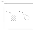
- Fig. 4 is an explanatory diagram illustrating pixels.
- a solvent which easily dissolves the receiving layer is largely contained as the ink composition
- color unevenness is generated in a pixel so that the shape becomes a pixel shape 100 as illustrated in Fig. 4 (a) .
- the shape of the pixel becomes close to an elliptical shape 110 as illustrated in Fig. 4 (b) .
- drying and solidifying the ink are performed.
- drying means and/or solidifying means any method among heating, air blast, reduced pressure, light irradiation, and electron beam irradiation or a combination of two or more kinds thereof can be used.
- Example 1 a method of preparing a reflection-type display on which a color filter is printed in a matrix shape will be described.
- a reflection-type display is prepared using a microcapsule-type electrophoretic system.
- a display device in this system is a device in which positively and negatively charged white particles and black particles are put into a microcapsule which is filled with a transparent solvent and an image is formed by pulling respective particles up to the display surface by applying an external voltage thereto. Since the size of the microcapsule is several tens of ⁇ m to several hundreds of ⁇ m, which is small, coating is possible like an ink when the microcapsule is allowed to be dispersed in a transparent binder. An image can be drawn with the ink when a voltage is applied from the outside.
- an active matrix display panel When a transparent resin film on which a transparent electrode is formed is coated with this electronic ink and the resin film is adhered to a substrate in which an electrode circuit for driving an active matrix is formed, an active matrix display panel can be obtained.
- a component in which a transparent resin film on which a transparent electrode is formed is coated with an electronic ink is referred to as a "front plane laminate,” and a substrate in which an electrode circuit for driving an active matrix is formed is referred to as a "back plane.”
- An ink holding layer is provided on a front plane laminate side.
- a material obtained by mixing an urethane-based resin, toluene, water, and IPA is used as a material of the ink receiving layer, and the material is applied such that the drying thickness thereof is within the range of 7 ⁇ m to 9 ⁇ m using a die coater.
- a Red ink contains 20 (% by weight) of a dispersed resin, 2 (% by weight) of a pigment, 58 (% by weight) of a solvent of diethylene glycol monoethyl ether acetate, 10 (% by weight) of benzyl alcohol, and 10 (% by weight) of butyl diglycol acetate.
- printing is performed in a grid-shaped pattern on the ink holding layer.
- a 3x3 droplet coating is performed so as to be put in the pixel size of a 160 ⁇ m square.
- the amount of one droplet is approximately 15 pL, and the printing is performed such that the interval between droplets becomes 40 ⁇ m. In this manner, the interval between pixels becomes in the range of 5 ⁇ m to 8 ⁇ m and the coloring rate in a pixel becomes approximately 90%.
- the chromaticity (x, y, Y) in a pixel is measured with a spot diameter of 10 ⁇ m using a spectroscope.
- the chromaticity of Red becomes an x of 0.431, a y of 0.305, and a Y of 42.1 in the center and an x of 0.422, a y of 0.307, and a Y of 45.8 in a site close to the outer peripheral portion.
- a difference among colors is 0.01 or smaller, which can be said to be a small number.
- the protective film is laminated thereon, and a color reflection-type display is prepared.
- a Red ink contains 20 (% by weight) of a dispersed resin, 2 (% by weight) of a pigment, 18 (% by weight) of a solvent of diethylene glycol monoethyl ether acetate, 50 (% by weight) of benzyl alcohol, and 10 (% by weight) of butyl diglycol acetate.
- printing is performed in a grid-shaped pattern on the ink holding layer. As the printing pattern, a 3x3 droplet coating is performed so as to be put in the pixel size of a 160 ⁇ m square.
- the amount of one droplet is approximately 15 pL, and the printing is performed such that the interval between droplets becomes 40 ⁇ m.
- a gap is generated between droplets, which is referred to as a void in a pixel formed using the ink. That is, when a ratio of benzyl alcohol to the ink composition is extremely high, a pixel with a uniform color cannot be formed and a color filter layer with high efficiency cannot be formed.
- the invention can be applied to a reflection-type display such as electronic paper.
Landscapes
- Chemical & Material Sciences (AREA)
- Engineering & Computer Science (AREA)
- Life Sciences & Earth Sciences (AREA)
- Physics & Mathematics (AREA)
- Materials Engineering (AREA)
- Wood Science & Technology (AREA)
- Organic Chemistry (AREA)
- Nonlinear Science (AREA)
- Optics & Photonics (AREA)
- General Physics & Mathematics (AREA)
- Manufacturing & Machinery (AREA)
- Ceramic Engineering (AREA)
- Health & Medical Sciences (AREA)
- Chemical Kinetics & Catalysis (AREA)
- Molecular Biology (AREA)
- Electrochemistry (AREA)
- Mathematical Physics (AREA)
- Crystallography & Structural Chemistry (AREA)
- Optical Filters (AREA)
- Inks, Pencil-Leads, Or Crayons (AREA)
- Ink Jet (AREA)
- Ink Jet Recording Methods And Recording Media Thereof (AREA)
Abstract
Description
- The present invention relates to an ink for an inkjet, a color filter, a manufacturing method therefor, a reflection-type display, and a manufacturing method therefor.
- With the spread of electronic information networks, electronic publishing represented by e-books has been performed. A device displaying electronic publishing and electronic information, a self-luminous-type display device or a backlight-type display device has been used. However, when compared to a medium printed on paper, these display devices make a user get easily fatigued due to ergonomic reasons when used for a long period of time. Further, since power consumption is large, the time for display is restricted when the display device is driven by a battery. In contrast to these drawbacks, since characters can be read from a reflection-type display represented by electronic paper in a sense close to paper, fatigue can be reduced. In addition, since display performance can be exhibited in a place getting sunshine or light outdoors, the reflection-type display is suitable for outdoor signage. Further, power consumption is low so that the device can be driven for a long period of time. Since power is not consumed other than when rewriting the screen, the reflection-type device is extensively used for digital signage or electronic shelf label and development of the reflection-type display has been extensively active.
- In the reflection-type display represented by electronic paper, when the reflection-type display is necessary to display only character information of e-books, a white and black display is sufficient, but a color display is vital technology to enhance illustrations of e-books, advertisements, signage, an eye-catching effect, images, or catalogs and, accordingly, color displays have been highly demanded with the colorization of display content. Here, as colorization of the reflection-type display, the following method has been proposed.
- A reflection-type display and a color filter are combined, and a color area intended to be displayed is set to white display according to a pattern displayed on a monochrome display device and a color area intended to be hidden is set to black display, as a result, display with a color pattern becomes possible (PTL 1).
- As a color filter layer for a reflection-type display, a method of performing color filter arrangement according to an electrode pattern displayed on a monochrome display device has been proposed (PTL 2).
-
- PTL 1:
JP-A-2003-161964 - PTL 2:
JP-A-2003-107234 - PTL 3:
JP-A-1-86116 - PTL 4:
JP-A-2000-43405 - PTL 5:
JP-A-2008-272972 - PTL 6:
JP-A-2000-238408 - In a method disclosed in PTL 1, it is possible to easily provide a color function by combining a reflection-type display and a color filter when a color function is provided. However, in a case of a color filter for a reflection-type display, since a light shielding portion referred to as a black matrix is provided, extraction efficiency becomes worse due to reflection of light because the color filter for a reflection-type display is different from a color filter for a liquid display, it is not necessary to provide a black matrix.
- When the color filter to which a black matrix is not provided is prepared, it is necessary for the color filter to receive an ink in a manner in which colors are not mixed. For this purpose, an ink is required to be received by a substrate using a known technology of ink reception such as providing a transparent partition instead of the black matrix or providing an ink receiving layer on a substrate.
- In the case where the transparent partition is provided, a problem in that the reflectance is decreased is generated due to the area of the partition portion. Further, when a bank with light permeability is used, there is a problem in that the cost is increased because processes for preparing the bank are further increased, alignment accuracy of the partition portion is needed, and the thickness of the partition is required to be thin. Providing the ink receiving layer is common because the cost of preparing the color filter is low. Colored pixels are printed on the ink receiving layer using a printing technology such as an inkjet method or a printing method.
- A method in which color printing is directly performed on a reflection-type display using an inkjet method and alignment is unnecessitated by removing a process of adhering the color filter to the reflection-type display is proposed. In addition, since the inkjet method is non-contact printing, foreign substances are small, and there is an advantage that the cost becomes low when compared to printing using a plate because the inkjet method is non-plate printing.
- However, in a color reflection-type display using a color filter system, in a case where the same color reproducibility is exhibited, when the coloring rate in a pixel is decreased, it is necessary to increase the density or the film thickness of an ink, therefore, the transmittance of the ink is decreased and the reflectance thereof is decreased as well. However, by increasing the coloring rate in a pixel, it is possible to adjust the density or the film thickness of the ink to be low and increase the transmittance of the ink.
- That is, by increasing the coloring rate in a pixel, it is possible to exhibit the reflectance and color reproducibility to the maximum, which is a problem of the color reflection-type display. However, when the size of a pixel is simply increased, colors become mixed due to overlapping pixels. Accordingly, in order to increase the coloring rate in a pixel, making the shape of a pixel close to a rectangular shape, improving the coating accuracy, and preventing the mixture of colors become problems to be solved.
- In order for the shape of a pixel to be close to a rectangular shape, it is necessary for the ink receiving layer to reliably receive ink droplets. In other words, the shape of a pixel cannot be made into a rectangular shape since the ink may become a circular shape due to the surface tension when ink droplets are printed on a substrate which does not receive ink droplets. However, in a case of an ink receiving layer that absorbs the whole ink droplet, the ink density doubles at the site that where droplets are overlapped and triples at a site where three droplets are overlapped. At this time, it is impossible to uniformize the ink density in one pixel, so that color tone adjustment becomes impossible. Further, when a distance between droplets is generated, this causes a state in which pixels are omitted, which is referred to as a void, and the void appears as unevenness at the time of the formation of a color filter. That is, in one pixel, the problem is to achieve two elements of suppressing color unevenness not by absorbing the ink to some extent but by mixing the ink, and making the pixel shape close to a rectangular shape by receiving the ink.
- An object of the invention is to provide an ink whose color in an ink colored pixel is uniform and which has a high absorption ratio to a receiving layer in the formation of a colored pixel in an inkjet system, and to create a color reflection-type display capable of achieving both white reflectance and color reproducibility.
- According to a first invention, there is provided an ink for a piezoelectric driving-type inkjet for printing on a resin-based ink receiving layer formed on one surface of a reflection-type display, the ink containing 30% by weight to 75% by weight of a solvent which hardly dissolves the ink receiving layer and 3% by weight to 30% by weight of an alcohol-based solvent which easily dissolves the ink receiving layer.
- According to a second the invention, the ink for an inkjet according to the first invention further contains: at least one kind of pigment for coloring or dye for coloring in the range of 0.5% by weight to 10% by weight; an organic solvent of carbitols in the range of 30% by weight to 75% by weight as a solvent which hardly dissolves the ink receiving layer; and benzyl alcohol in the range of 3% by weight to 30% by weight as an alcohol-based solvent which easily dissolves the ink receiving layer.
- According to a third invention, in the ink for an inkjet according to the first or second invention, a fluorine-based surfactant is further contained in the range of 0.01% by weight to 3.00% by weight.
- According to a fourth invention, there is provided a color filter which is configured using the ink for an inkjet according to any one of the first to third inventions.
- According to a fifth invention, there is provided a color reflection-type display which includes the color filter according to the fourth invention.
- According to a sixth invention, there is provided a method of manufacturing a color filter which includes performing inkjet ejection with respect to a surface on which the inkjet receiving layer of the reflection-type display is provided using the ink for an inkjet according to any one of the first to third inventions to form a color filter.
- According to a seventh invention, the method of manufacturing a color filter according to the sixth invention further includes preparing a long hole-shaped pattern by continuously discharging an ink droplet impacting portion in the inkjet ejection and forming a pixel colored portion by arranging the long hole-shaped pattern.
- According to an eighth invention, there is provided a method of manufacturing a color reflection type display which includes performing inkjet ejection with respect to a surface on which the ink receiving layer of the reflection type display is provided and forming a color filter using the ink for an inkjet according to any one of the first to third inventions to manufacture a color reflection-type display.
- According to the first and second inventions, an ink for an inkjet capable of achieving ink receiving performance with respect to an ink receiving layer and color-uniformizing performance due to wet spreading of the ink in the ink colored pixels can be provided, and an arbitrary pixel shape whose color tone can be adjusted can be formed.
- According to the third invention, by decreasing the surface tension of the ink, it is possible to change color distribution in the ink colored pixel and to adjust the shape and the color tone of the colored pixel.
- According to the fourth invention, it is possible to create a color filter without color unevenness and with a high coloring rate in a pixel.
- According to the fifth invention, it is possible to provide an ink with uniform color in the ink colored pixel and with a high absorption ratio to the receiving layer and to create a color reflection-type display capable of achieving white reflectance and color reproducibility.
- According to the sixth invention, it is possible to create a color filter without color unevenness and with a high coloring rate in a pixel.
- According to the seventh invention, it is possible to form the pixel colored portion in a shape close to a rectangular shape.
- According to the eighth invention, it is possible to provide an ink with uniform color in the ink colored pixel and a high absorption rate to the receiving layer, and to create a color reflection-type display capable of achieving white reflectance and color reproducibility.
- As understood from the respective configurations described above, according to the invention, it is possible to provide an ink with uniform color in the ink colored pixel and a high absorption rate to the receiving layer, and to create a color reflection-type display capable of achieving white reflectance and color reproducibility in the formation of the colored pixel in the inkjet system.
-
- [
Fig. 1] Fig. 1 illustrates an embodiment of the invention, and is an explanatory diagram of a configuration of a color reflection-type display. - [
Fig. 2] Fig. 2 illustrates the embodiment of the invention, and is an explanatory diagram of an inkjet printer. - [
Fig. 3] Fig. 3 illustrates the embodiment of the invention, andFigs. 3(a) and 3(b) are explanatory diagrams of a method of forming a colored pixel. - [
Fig. 4] Fig. 4 illustrates the embodiment of the invention, andFigs. 4(a) and 4(b) are explanatory diagrams of a shape of the colored pixel. - Hereinafter, embodiments of the invention will be described in detail.
- A color reflection-type display of the invention is a display obtained by combining a monochrome reflection-type display and a color filter or by adding a color printing process using an inkjet method to a process of preparing an existing monochrome reflection-type display.
- In a reflection-type display generally represented by electronic paper, as a method of preparing an electrophoretic display device which is a kind of electronic paper, an electrophoretic display device sealing a dispersion system which contains electrophoretic particles between counter electrode plates whose at least one surface is a light transmissive type and performing required display by changing optical reflection characteristics using a voltage for display control, which is applied to a space between the electrodes, described in PTL 3, is exemplified.
- The color filter of the invention is used by combining with the reflection-type display, and a color filter layer may be directly formed on the reflection-type display. At this time, the ink receiving layer is provided on the electrode layer of the reflection-type display to form a color filter layer using an inkjet method.
Fig. 1 is an explanatory diagram illustrating the layer configuration of color electronic paper as an example of the reflection-type display. The color electronic paper has a configuration in which an electrode layer 2, an electrode pattern layer 3, a microcapsule layer 4, a light transmissive electrode layer 5, an electrode sheet layer 6, an ink holding layer 7, acolor filter layer 8, and a protective film 9 are sequentially laminated on a substrate layer 1. - As the ink receiving layer, that is, the ink holding layer 7 of the invention, for example, an inkjet recording medium described in PTL 4 and a recording medium for an inkjet printer described in PTL 5 can be used. Particularly, a layer with high transparency is preferable. However, as described in PTL 6, a receiving material for an inkjet having a porous structure cannot be used as the ink receiving layer of the invention. This is because uniformity of wet spreading is damaged due to the ink infiltrated in the layer in a case where the ink receiving layer has a porous structure. That is, the ink receiving layer is required to be a type that holds the ink on the film. A material of the ink receiving layer is necessary to have performance of transparency and various resistances and is free from discoloration or color-fading of the received ink, and preferred examples thereof include a vinyl resin such as polyvinyl butyral or polyvinyl acetate. A solvent of the ink receiving layer is configured using an aqueous solvent such as water or IPA or an alcohol solvent.
- Coating is performed such that the material of the ink receiving layer has a thickness of, for example, 4 µm to 10 µm after being dried using a coating apparatus. The coating apparatus performs coating using a die coater, a spin coater, or a bar coater. However, the coating methods are not limited to these methods.
- The ink receiving layer is formed by applying the ink receiving layer material thereto and then solidifying the material by a method using heat, vacuum, or UV irradiation.
- The material of the colored ink of the invention contains a colorant, a resin, a dispersant, and a solvent. The colorant of the ink may be one of a pigment and a dye. It is preferable that three kinds of colors which are red, green, and blue be used for the color tone thereof, but yellow, light blue, or violet may be used. In addition, a combination of colors is not limited and only two kinds of colors may be combined.
- Specific examples of pigments being used as colorants include Pigment Red 9, 19, 38, 43, 97, 122, 123, 144, 149, 166, 168, 177, 179, 180, 192, 215, 216, 208, 216, 217, 220, 223, 224, 226, 227, 228, and 240; Pigment Blue 15, 15:6, 16, 22, 29, 60, and 64; Pigment Green 7 and 36;
Pigment Red - Examples of the resin of the colored ink material include casein, gelatin, polyvinyl alcohol, carboxymethyl acetal, a polyimide resin, an acrylic resin, an epoxy resin, and a melamine resin, and the resin can be appropriately selected from a relationship with the color tone. When heat resistance or light resistance is required, an acrylic resin is preferable.
- A dispersant may be used to improve dispersion of a colorant to a resin, and examples of the dispersant include a non-ionic surfactant such as polyoxyethylene alkyl ether; an ionic surfactant such as sodium alkylbenzene sulfonate, a poly fatty acid salt, fatty acid salt alkyl phosphate, or a teteraalkyl ammonium salt; an organic pigment derivative; and polyester. The dispersant may be used alone or in combination of two or more kinds thereof.
- As the solvent used for a colored ink, a solvent having a surface tension of 35 mN/m or smaller which is a proper value for the inkjet printing and having a boiling point of 130°C or higher is preferable. When the surface tension is 35 mN/m or greater, this adversely and significantly affects stability of a dot shape at the time of inkjet ejection. In addition, when the boiling point thereof is 130°C or lower, a drying property in the vicinity of nozzles becomes significantly increased, as a result, this leads to generation of defects such as nozzle clogging, which is not preferable. It is preferable to adjust the viscosity to be in the range of 5 cps to 20 cps. The present inventors found that the solvent used for the ink significantly affects the ink absorption amount of the ink receiving layer. In other words, when a ratio in an ink of a solvent which easily dissolves the ink receiving layer to the ink is increased, ink receiving performance is improved, and when a solvent which hardly dissolves or does not dissolve the ink receiving layer is used, the ink receiving performance is decreased and the wettability of droplets is improved. Specifically, in a case where the ink receiving layer which can be dissolved in an aqueous solvent is formed, a solvent in which the receiving layer is not dissolved much such as carbitols and an alcohol-based solvent which easily dissolves the receiving layer are used in the ink. In addition, by controlling the ratio thereof, it is possible to achieve both of the ink receiving property and color uniformity in a pixel. The carbitols indicate carbitol-based solvents such as diethylene glycol monomethyl ether, diethylene glycol monoethyl ether, and diethylene glycol monobutyl ether; these cellosolves, and acetate compounds such as carbitols.
- As an alcohol-based solvent which easily dissolves the receiving layer, benzyl alcohol is used. Further, as a solvent in which the receiving layer is not dissolved much, diethylene glycol monoethyl ether acetate and butyl glycol acetate are used. As the ink composition, 20 (% by weight) of a dispersed resin, 2 (% by weight) of a pigment, 58 (% by weight) of a solvent of diethylene glycol monoethyl ether acetate, 10 (% by weight) of benzyl alcohol, and 10 (% by weight) of butyl diglycol acetate are set to be prepared.
- In a case where a ratio of solvent components in which the receiving layer is not dissolved much to the ink composition is set to 30 (% by weight) or smaller and a ratio of an alcohol-based solvent which easily dissolves the receiving layer to the ink composition is set to 30 (% by weight) or greater, the ink is infiltrated into the receiving layer at the time when the ink is printed on the receiving layer and a gap is generated between droplets which is referred to as a void. In addition, in a case where a ratio of solvent components in which the receiving layer is not dissolved much to the ink composition is set to 75 (% by weight) or greater and a ratio of an alcohol-based solvent which easily dissolves the receiving layer to the ink composition is set to 3 (% by weight) or smaller, the reception performance is deteriorated so that the shape becomes a circular shape due to the surface tension of the ink. Accordingly, in order for the invention to exhibit a further effect, it is understood that the ratio of the ink composition having an organic solvent of carbitols in the range of 30% by weight to 75% by weight and benzyl alcohol in the range of 3% by weight to 30% by weight is preferable. Moreover, the ink may contain at least one kind of pigment for coloring or dye for coloring in the range of 0.5% by weight to 10% by weight.
- In a case where a silicone-based material or a fluorine-based material is added to the ink as a surfactant, the surface tension of the ink is decreased and wet spreading becomes large. It is found that the color uniformity in a pixel can be improved using this property. As an example of the surfactant, a silicone resin or silicone rubber which includes organic silicone or an alkyl fluoro group in the main chain or the side chain thereof and contains a siloxane component; vinylidene fluoride; vinyl fluoride; trifluoroethylene; and a fluorine resin of these copolymers or the like can be used. A silicone-based compound or a fluorine-based compound is provided in a solid content ratio of 0.01 (% by weight) to 3.00 (% by weight). In a case where the addition amount thereof is smaller than 0.01 (% by weight), the wet spreading effect is not significant. In a case where the addition amount thereof is 3.00 (% by weight) or greater, since the surface tension of the ink is extremely decreased, ejection performance of the inkjet becomes degraded. Therefore, when the ink receiving property and the uniformity in a pixel are controlled using a surfactant, the addition amount of the surfactant is adjusted to be within the range of 0.01 (% by weight) to 3.00 (% by weight).
- Pattern printing is performed on a transparent substrate for preparation of the color filter using the inkjet method. Moreover, printing of an arbitrary pattern is performed in accordance with an electrode substrate on which electrode wiring is patterned. In both cases, the ink receiving layer is formed on one surface in advance.
- Next, the embodiment of an inkjet apparatus used in the invention will be described with reference to the accompanying drawings.
-
Fig. 2 is an explanatory diagram of aninkjet coating apparatus 40 in a method of manufacturing color electronic paper of the invention. As the configuration of the apparatus, the coating apparatus includes a conveyingstage 30 which carries a reflection-type display 20 and conveys the reflection-type display in one direction with high precision, anink tank 70, aninkjet head 10 to which an inkjet ink for applying to a reflection-type display panel is supplied from theink tank 70, aninkjet head unit 60 capable of moving theinkjet head 10 in a direction orthogonal to the conveyance direction by holding a certain level of height from the reflection-type display 20, and a dryingunit 50. - A piezoelectric driving-type inkjet head is used for the
inkjet head 10. A plurality of nozzles ejecting the ink are included, and the nozzles are arranged to have predetermined intervals with respect to a scanning direction in which theinkjet head 10 is relatively scanned with respect to a colored pixel pattern (hereinafter, simply referred to as a pixel pattern) of a color filter layer. Further, an inkjethead control substrate 11 for ejecting and controlling the inkjet ink from the nozzles of theinkjet head 10 is included. By setting the distance from the nozzles of theinkjet head 10 to the reflection-type display 20 to 300 µm to 2000 µm, coating can be performed with high coating precision. The risk of theinkjet head 10 coming into contact with the reflection-type display 20 is increased when the distance thereof is 300 µm or less, and an ejection flying curve (misdirection) is easily generated when the distance thereof is 2000 µm or greater. In addition, amaintenance apparatus 12 for recovering an ejecting property of the nozzles of theinkjet head 10 is included. Themaintenance apparatus 12 includes a pot or the like for performing wiping or ejecting a liquid on the nozzle surface using a rag or a film, and a commonly used inkjethead maintenance mechanism 12 can be used. In order to determine a position of a pixel pattern of coating color electronic paper, it is preferable to include a camera for alignment and an image processing unit. Even in a case where a color filter pattern is printed on a transparent base material, since an alignment mark for adhering with the reflection-type display panel is needed for the base material, it is preferable to include a camera for alignment and an image processing unit. - In the invention, using the
inkjet coating apparatus 40 illustrated inFig. 2 , theinkjet head 10 including a plurality of nozzles is relatively scanned with respect to the pixel pattern, the inkjet ink is ejected and supplied to a surface on which the ink receiving layer of the reflection-type display 20 is provided, and an inkjet ink layer, that is, a color filter layer is formed on the ink receiving layer. Further, in the invention, theinkjet head 10 including the plurality of nozzles is relatively scanned with respect to the pixel pattern. As illustrated inFig. 2 , the reflection-type display 20 side may be scanned or theinkjet head 10 side may be scanned. In addition, both of the reflection-type display 20 and theinkjet head 10 may be operated. - It is preferable to perform inkjet ejection arrangement according to the size of the pixel for the pixel shape of the invention to be close to a rectangular shape. That is, it is preferable to prepare a pattern with precision higher than that of a relationship among the pixel size, the droplets, and the impacting area.
Fig. 3 is an explanatory diagram illustrating the pixel shape and the ejection arrangement pattern. As illustrated inFig. 3(a) , an inkdroplet impacting unit 80 is continuously ejected to prepare long hole-shaped pixels. At this time, since the shape becomes recessed in a case where an interval F between ink droplets is long and the center portion becomes projected in a case where the interval is short, it is preferable to adjust the droplet diameter and the interval F and prepare a shape which is longitudinally linear. As illustrated inFig. 3(b) , an arbitrary number of the long hole shapes are horizontally arranged to form a predetermined pixelcolored portion 90. -
Fig. 4 is an explanatory diagram illustrating pixels. In a case where a solvent which easily dissolves the receiving layer is largely contained as the ink composition, color unevenness is generated in a pixel so that the shape becomes apixel shape 100 as illustrated inFig. 4 (a) . In addition, in a case where a solvent which hardly dissolves the receiving layer is largely contained, the shape of the pixel becomes close to anelliptical shape 110 as illustrated inFig. 4 (b) . - After the ink receiving layer is coated with the ink, drying and solidifying the ink are performed. As drying means and/or solidifying means, any method among heating, air blast, reduced pressure, light irradiation, and electron beam irradiation or a combination of two or more kinds thereof can be used.
- After the ink is dried and solidified, a protective film may be formed for protection of the color filter layer. In order to form the protective film of the color filter, an organic resin such as polyamide, polyimide, polyurethane, polycarbonate, an acrylic resin, or a silicone-based resin or an inorganic film such as Si3N4, SiO2, SiO, Al2O3, or Ta2O3 can be provided on the surface of the colored pattern as a protective film using a coating method such as spin coating, roll coating, or a printing method; or a deposition method. In a case where the surface of the color filter layer is adhered to the reflection-type display and the color filter base material has a function of protecting the color filter layer, the protective film may not be formed.
- As Example 1, a method of preparing a reflection-type display on which a color filter is printed in a matrix shape will be described.
- A reflection-type display is prepared using a microcapsule-type electrophoretic system. A display device in this system is a device in which positively and negatively charged white particles and black particles are put into a microcapsule which is filled with a transparent solvent and an image is formed by pulling respective particles up to the display surface by applying an external voltage thereto. Since the size of the microcapsule is several tens of µm to several hundreds of µm, which is small, coating is possible like an ink when the microcapsule is allowed to be dispersed in a transparent binder. An image can be drawn with the ink when a voltage is applied from the outside.
- When a transparent resin film on which a transparent electrode is formed is coated with this electronic ink and the resin film is adhered to a substrate in which an electrode circuit for driving an active matrix is formed, an active matrix display panel can be obtained. In general, a component in which a transparent resin film on which a transparent electrode is formed is coated with an electronic ink is referred to as a "front plane laminate," and a substrate in which an electrode circuit for driving an active matrix is formed is referred to as a "back plane."
- An ink holding layer is provided on a front plane laminate side. A material obtained by mixing an urethane-based resin, toluene, water, and IPA is used as a material of the ink receiving layer, and the material is applied such that the drying thickness thereof is within the range of 7 µm to 9 µm using a die coater.
- The ink composition will be described. As the ink composition used for printing, a Red ink contains 20 (% by weight) of a dispersed resin, 2 (% by weight) of a pigment, 58 (% by weight) of a solvent of diethylene glycol monoethyl ether acetate, 10 (% by weight) of benzyl alcohol, and 10 (% by weight) of butyl diglycol acetate.
- In the inkjet apparatus, printing is performed in a grid-shaped pattern on the ink holding layer. As the printing pattern, a 3x3 droplet coating is performed so as to be put in the pixel size of a 160 µm square. The amount of one droplet is approximately 15 pL, and the printing is performed such that the interval between droplets becomes 40 µm. In this manner, the interval between pixels becomes in the range of 5 µm to 8 µm and the coloring rate in a pixel becomes approximately 90%. In addition, the chromaticity (x, y, Y) in a pixel is measured with a spot diameter of 10 µm using a spectroscope. The chromaticity of Red becomes an x of 0.431, a y of 0.305, and a Y of 42.1 in the center and an x of 0.422, a y of 0.307, and a Y of 45.8 in a site close to the outer peripheral portion. A difference among colors is 0.01 or smaller, which can be said to be a small number.
- After the color filter layer is dried using hot air at 100°C for 5 minutes, the protective film is laminated thereon, and a color reflection-type display is prepared.
- The same reflection-type display and receiving layer as those in Example 1 are used here. As the ink composition, a Red ink contains 20 (% by weight) of a dispersed resin, 2 (% by weight) of a pigment, 18 (% by weight) of a solvent of diethylene glycol monoethyl ether acetate, 50 (% by weight) of benzyl alcohol, and 10 (% by weight) of butyl diglycol acetate. In the inkjet apparatus, printing is performed in a grid-shaped pattern on the ink holding layer. As the printing pattern, a 3x3 droplet coating is performed so as to be put in the pixel size of a 160 µm square. The amount of one droplet is approximately 15 pL, and the printing is performed such that the interval between droplets becomes 40 µm. A gap is generated between droplets, which is referred to as a void in a pixel formed using the ink. That is, when a ratio of benzyl alcohol to the ink composition is extremely high, a pixel with a uniform color cannot be formed and a color filter layer with high efficiency cannot be formed.
- The invention can be applied to a reflection-type display such as electronic paper.
-
- 1: SUBSTRATE LAYER
- 2: ELECTRODE LAYER
- 3: ELECTRODE PATTERN LAYER
- 4: MICROCAPSULE LAYER
- 5: LIGHT TRANSMISSIVE ELECTRODE LAYER
- 6: ELECTRODE SHEET LAYER
- 7: INK HOLDING LAYER
- 8: COLOR FILTER LAYER
- 9: PROTECTIVE LAYER
- 10: INKJET HEAD
- 11: INKJET HEAD CONTROL SUBSTRATE
- 12: INKJET HEAD MAINTENANCE MECHANISM
- 20: REFLECTION-TYPE DISPLAY
- 30: CONVEYING STAGE
- 40: INKJET COATING APPARATUS
- 50: DRYING UNIT
- 60: INKJET HEAD UNIT
- 70: INK TANK
- 80: INK DROPLET IMPACTING UNIT
- 90: PIXEL COLORED PORTION
- 100: PIXEL SHAPE (PIXEL CRACK)
- 110: PIXEL SHAPE (ELLIPTICAL SHAPE)
Claims (8)
- An ink for a piezoelectric driving-type inkjet for printing on a resin-based ink receiving layer formed on one surface of a reflection-type display, containing:30% by weight to 75% by weight of a solvent which hardly dissolves the ink receiving layer and 3% by weight to 30% by weight of an alcohol-based solvent which easily dissolves the ink receiving layer.
- The ink for an inkjet according to claim 1, further containing:at least one kind of pigment for coloring or dye for coloring in the range of 0.5% by weight to 10% by weight;an organic solvent of carbitols in the range of 30% by weight to 75% by weight as a solvent which hardly dissolves the ink receiving layer; andbenzyl alcohol in the range of 3% by weight to 30% by weight as an alcohol-based solvent which easily dissolves the ink receiving layer.
- The ink for an inkjet according to claim 1 or 2, further containing:a fluorine-based surfactant in the range of 0.01% by weight to 3.00% by weight.
- A color filter which is configured using the ink for an inkjet according to any one of claims 1 to 3.
- A color reflection-type display comprising the color filter according to claim 4.
- A method of manufacturing a color filter, comprising:performing inkjet ejection with respect to a surface on which the inkjet receiving layer of the reflection-type display is provided using the ink for an inkjet according to any one of claims 1 to 3 to form a color filter.
- The method of manufacturing a color filter according to claim 6, further comprising:preparing a long hole-shaped pattern by continuously discharging an ink droplet impacting portion in the inkjet ejection and forming a pixel colored portion by arranging the long hole-shaped pattern.
- Amethod of manufacturing a color reflection type display, comprising:performing inkjet ejection with respect to a surface on which the ink receiving layer of the reflection type display is provided and forming a color filter using the ink for an inkjet according to any one of claims 1 to 3 to manufacture a color reflection-type display.
Applications Claiming Priority (2)
| Application Number | Priority Date | Filing Date | Title |
|---|---|---|---|
| JP2012183347 | 2012-08-22 | ||
| PCT/JP2013/004935 WO2014030345A1 (en) | 2012-08-22 | 2013-08-21 | Ink for inkjet and color filter and manufacturing method therefor, and color reflective display and manufacturing method therefor |
Publications (3)
| Publication Number | Publication Date |
|---|---|
| EP2840120A1 true EP2840120A1 (en) | 2015-02-25 |
| EP2840120A4 EP2840120A4 (en) | 2015-12-16 |
| EP2840120B1 EP2840120B1 (en) | 2019-08-07 |
Family
ID=50149671
Family Applications (1)
| Application Number | Title | Priority Date | Filing Date |
|---|---|---|---|
| EP13830651.9A Not-in-force EP2840120B1 (en) | 2012-08-22 | 2013-08-21 | Ink for inkjet and color filter and manufacturing method therefor, and color reflective display and manufacturing method therefor |
Country Status (6)
| Country | Link |
|---|---|
| US (1) | US9988544B2 (en) |
| EP (1) | EP2840120B1 (en) |
| JP (1) | JP6304031B2 (en) |
| CN (1) | CN104321392B (en) |
| TW (1) | TWI628242B (en) |
| WO (1) | WO2014030345A1 (en) |
Cited By (1)
| Publication number | Priority date | Publication date | Assignee | Title |
|---|---|---|---|---|
| US10333036B2 (en) | 2016-06-23 | 2019-06-25 | eLux Inc. | Absorptive color conversion film |
Families Citing this family (3)
| Publication number | Priority date | Publication date | Assignee | Title |
|---|---|---|---|---|
| US10418585B2 (en) * | 2016-05-12 | 2019-09-17 | Samsung Display Co., Ltd. | Cover unit and display device having the same |
| CN110137166A (en) * | 2019-05-06 | 2019-08-16 | 深圳市晶台股份有限公司 | A kind of LED filter layer constructive method based on ink-jet technology |
| JP7378262B2 (en) * | 2019-10-11 | 2023-11-13 | スリーエム イノベイティブ プロパティズ カンパニー | Inkjet printing method and inkjet printing device |
Family Cites Families (24)
| Publication number | Priority date | Publication date | Assignee | Title |
|---|---|---|---|---|
| JP2551783B2 (en) | 1987-09-29 | 1996-11-06 | エヌオーケー株式会社 | Electrophoretic display device |
| JPH0637527Y2 (en) | 1987-11-30 | 1994-09-28 | 岩崎電気株式会社 | Connectable fluorescent lighting |
| JP2000043405A (en) | 1998-07-27 | 2000-02-15 | Toppan Printing Co Ltd | INK JET RECORDING MEDIUM AND ITS MANUFACTURING METHOD |
| JP4507286B2 (en) * | 1998-10-02 | 2010-07-21 | 凸版印刷株式会社 | Color filter for display device and reflection type display device |
| JP3967841B2 (en) | 1999-02-22 | 2007-08-29 | 富士フイルム株式会社 | Inkjet image receiving material and method for producing the same |
| JP2002311223A (en) * | 2001-04-12 | 2002-10-23 | Canon Inc | Color filter, method of manufacturing the same, and liquid crystal element using the color filter |
| JP4415525B2 (en) | 2001-09-27 | 2010-02-17 | 凸版印刷株式会社 | Color filter for reflective color display and reflective color display including the same |
| JP2003161964A (en) | 2001-11-22 | 2003-06-06 | Toppan Printing Co Ltd | Multi-color display panel |
| JP2003261827A (en) * | 2002-03-07 | 2003-09-19 | Sekisui Chem Co Ltd | Colored resin emulsion, ink for inkjet printing and color filter |
| KR100736531B1 (en) * | 2005-03-16 | 2007-07-06 | 주식회사 엘지화학 | Step-adjustable ink |
| CN100543091C (en) * | 2005-06-17 | 2009-09-23 | 虹创科技股份有限公司 | Ejection ink for colorful light filter |
| JP2006209115A (en) * | 2006-01-23 | 2006-08-10 | Toppan Printing Co Ltd | Color filter for display device and display device |
| JP2008272972A (en) | 2007-04-26 | 2008-11-13 | Furukawa Electric Co Ltd:The | Recording medium for ink jet printer |
| JP5292039B2 (en) * | 2008-03-07 | 2013-09-18 | 富士フイルム株式会社 | Azo pigment composition, method for producing azo pigment composition, dispersion containing azo pigment composition, coloring composition, and ink for ink jet recording |
| JP5380098B2 (en) * | 2008-03-07 | 2014-01-08 | 富士フイルム株式会社 | Azo compound, azo pigment and dispersion containing azo compound or azo pigment, coloring composition, ink for ink jet recording, ink tank for ink jet recording, ink jet recording method, and recorded matter |
| US20090284698A1 (en) * | 2008-05-16 | 2009-11-19 | Mi-Kyoung Kim | Ink composition, color filter manufactured by using the same, and display device comprising the same |
| JP2010276986A (en) * | 2009-05-29 | 2010-12-09 | Bridgestone Corp | Transparent substrate with color filter, information display panel with color filter, and method for manufacturing the substrate and the panel |
| TW201105753A (en) * | 2009-06-04 | 2011-02-16 | Fujifilm Corp | Ink set, color filter and process for preparing color filter, and liquid crystal display and image display device using color filter |
| JP2011057834A (en) * | 2009-09-09 | 2011-03-24 | Fujifilm Corp | Ink for inkjet, color filter and method for producing the same, and liquid crystal display and image display device using the same |
| JP5505656B2 (en) * | 2011-04-27 | 2014-05-28 | Jsr株式会社 | Pigment dispersion composition, resin composition for inkjet color filter, color filter, and liquid crystal display device |
| JP2013040240A (en) * | 2011-08-11 | 2013-02-28 | Fujifilm Corp | Azo compound, azo pigment, pigment dispersion, coloring composition, colored composition for color filter, color filter, preparation method of colored composition for color filter, ink for inkjet recording, printing ink, coating, dye, and resist ink |
| EP2762970B1 (en) * | 2011-09-28 | 2017-08-16 | Toppan Printing Co., Ltd. | Electronic paper and method for manufacturing same |
| JP5957837B2 (en) * | 2011-09-30 | 2016-07-27 | 凸版印刷株式会社 | Color filter and reflective display device having the same |
| WO2013141257A1 (en) * | 2012-03-23 | 2013-09-26 | 凸版印刷株式会社 | Color reflective display device and method for manufacturing same |
-
2013
- 2013-08-21 CN CN201380026464.3A patent/CN104321392B/en not_active Expired - Fee Related
- 2013-08-21 EP EP13830651.9A patent/EP2840120B1/en not_active Not-in-force
- 2013-08-21 JP JP2014531503A patent/JP6304031B2/en not_active Expired - Fee Related
- 2013-08-21 WO PCT/JP2013/004935 patent/WO2014030345A1/en not_active Ceased
- 2013-08-22 TW TW102129942A patent/TWI628242B/en not_active IP Right Cessation
-
2015
- 2015-02-23 US US14/628,832 patent/US9988544B2/en active Active
Cited By (1)
| Publication number | Priority date | Publication date | Assignee | Title |
|---|---|---|---|---|
| US10333036B2 (en) | 2016-06-23 | 2019-06-25 | eLux Inc. | Absorptive color conversion film |
Also Published As
| Publication number | Publication date |
|---|---|
| WO2014030345A1 (en) | 2014-02-27 |
| EP2840120A4 (en) | 2015-12-16 |
| TW201408738A (en) | 2014-03-01 |
| EP2840120B1 (en) | 2019-08-07 |
| CN104321392A (en) | 2015-01-28 |
| US20150275009A1 (en) | 2015-10-01 |
| TWI628242B (en) | 2018-07-01 |
| CN104321392B (en) | 2017-10-24 |
| JP6304031B2 (en) | 2018-04-04 |
| JPWO2014030345A1 (en) | 2016-07-28 |
| US9988544B2 (en) | 2018-06-05 |
Similar Documents
| Publication | Publication Date | Title |
|---|---|---|
| JP6233299B2 (en) | Color reflection type display device and manufacturing method thereof | |
| US9988544B2 (en) | Ink for inkjet, color filter, manufacturing method therefor, color reflection-type display, and manufacturing method therefor | |
| US9256112B2 (en) | Electronic paper and method for manufacturing the same | |
| JP6287843B2 (en) | Reflective color display | |
| CN104220906B (en) | Manufacturing method of color filter and color reflective display | |
| JP6221242B2 (en) | Manufacturing method of color filter | |
| JP2017095601A (en) | Colored ink, color filter, and reflective display device | |
| CN101021583A (en) | Colour optical filter separating wall and producing method thereof, colour filter and producing method thereof | |
| WO2017110077A1 (en) | Reflective display panel and production method therefor |
Legal Events
| Date | Code | Title | Description |
|---|---|---|---|
| PUAI | Public reference made under article 153(3) epc to a published international application that has entered the european phase |
Free format text: ORIGINAL CODE: 0009012 |
|
| 17P | Request for examination filed |
Effective date: 20141117 |
|
| AK | Designated contracting states |
Kind code of ref document: A1 Designated state(s): AL AT BE BG CH CY CZ DE DK EE ES FI FR GB GR HR HU IE IS IT LI LT LU LV MC MK MT NL NO PL PT RO RS SE SI SK SM TR |
|
| AX | Request for extension of the european patent |
Extension state: BA ME |
|
| DAX | Request for extension of the european patent (deleted) | ||
| RA4 | Supplementary search report drawn up and despatched (corrected) |
Effective date: 20151116 |
|
| RIC1 | Information provided on ipc code assigned before grant |
Ipc: G02B 5/20 20060101ALI20151110BHEP Ipc: G02F 1/167 20060101ALI20151110BHEP Ipc: B41M 5/00 20060101ALI20151110BHEP Ipc: C09D 11/00 20140101AFI20151110BHEP Ipc: G02F 1/1335 20060101ALI20151110BHEP |
|
| STAA | Information on the status of an ep patent application or granted ep patent |
Free format text: STATUS: EXAMINATION IS IN PROGRESS |
|
| 17Q | First examination report despatched |
Effective date: 20180301 |
|
| GRAP | Despatch of communication of intention to grant a patent |
Free format text: ORIGINAL CODE: EPIDOSNIGR1 |
|
| STAA | Information on the status of an ep patent application or granted ep patent |
Free format text: STATUS: GRANT OF PATENT IS INTENDED |
|
| INTG | Intention to grant announced |
Effective date: 20190416 |
|
| GRAS | Grant fee paid |
Free format text: ORIGINAL CODE: EPIDOSNIGR3 |
|
| GRAA | (expected) grant |
Free format text: ORIGINAL CODE: 0009210 |
|
| STAA | Information on the status of an ep patent application or granted ep patent |
Free format text: STATUS: THE PATENT HAS BEEN GRANTED |
|
| AK | Designated contracting states |
Kind code of ref document: B1 Designated state(s): AL AT BE BG CH CY CZ DE DK EE ES FI FR GB GR HR HU IE IS IT LI LT LU LV MC MK MT NL NO PL PT RO RS SE SI SK SM TR |
|
| REG | Reference to a national code |
Ref country code: GB Ref legal event code: FG4D |
|
| REG | Reference to a national code |
Ref country code: CH Ref legal event code: EP Ref country code: AT Ref legal event code: REF Ref document number: 1163823 Country of ref document: AT Kind code of ref document: T Effective date: 20190815 |
|
| REG | Reference to a national code |
Ref country code: DE Ref legal event code: R096 Ref document number: 602013058920 Country of ref document: DE |
|
| REG | Reference to a national code |
Ref country code: IE Ref legal event code: FG4D |
|
| REG | Reference to a national code |
Ref country code: NL Ref legal event code: MP Effective date: 20190807 |
|
| REG | Reference to a national code |
Ref country code: LT Ref legal event code: MG4D |
|
| PG25 | Lapsed in a contracting state [announced via postgrant information from national office to epo] |
Ref country code: NO Free format text: LAPSE BECAUSE OF FAILURE TO SUBMIT A TRANSLATION OF THE DESCRIPTION OR TO PAY THE FEE WITHIN THE PRESCRIBED TIME-LIMIT Effective date: 20191107 Ref country code: SE Free format text: LAPSE BECAUSE OF FAILURE TO SUBMIT A TRANSLATION OF THE DESCRIPTION OR TO PAY THE FEE WITHIN THE PRESCRIBED TIME-LIMIT Effective date: 20190807 Ref country code: NL Free format text: LAPSE BECAUSE OF FAILURE TO SUBMIT A TRANSLATION OF THE DESCRIPTION OR TO PAY THE FEE WITHIN THE PRESCRIBED TIME-LIMIT Effective date: 20190807 Ref country code: BG Free format text: LAPSE BECAUSE OF FAILURE TO SUBMIT A TRANSLATION OF THE DESCRIPTION OR TO PAY THE FEE WITHIN THE PRESCRIBED TIME-LIMIT Effective date: 20191107 Ref country code: LT Free format text: LAPSE BECAUSE OF FAILURE TO SUBMIT A TRANSLATION OF THE DESCRIPTION OR TO PAY THE FEE WITHIN THE PRESCRIBED TIME-LIMIT Effective date: 20190807 Ref country code: HR Free format text: LAPSE BECAUSE OF FAILURE TO SUBMIT A TRANSLATION OF THE DESCRIPTION OR TO PAY THE FEE WITHIN THE PRESCRIBED TIME-LIMIT Effective date: 20190807 Ref country code: PT Free format text: LAPSE BECAUSE OF FAILURE TO SUBMIT A TRANSLATION OF THE DESCRIPTION OR TO PAY THE FEE WITHIN THE PRESCRIBED TIME-LIMIT Effective date: 20191209 Ref country code: FI Free format text: LAPSE BECAUSE OF FAILURE TO SUBMIT A TRANSLATION OF THE DESCRIPTION OR TO PAY THE FEE WITHIN THE PRESCRIBED TIME-LIMIT Effective date: 20190807 |
|
| REG | Reference to a national code |
Ref country code: AT Ref legal event code: MK05 Ref document number: 1163823 Country of ref document: AT Kind code of ref document: T Effective date: 20190807 |
|
| PG25 | Lapsed in a contracting state [announced via postgrant information from national office to epo] |
Ref country code: GR Free format text: LAPSE BECAUSE OF FAILURE TO SUBMIT A TRANSLATION OF THE DESCRIPTION OR TO PAY THE FEE WITHIN THE PRESCRIBED TIME-LIMIT Effective date: 20191108 Ref country code: LV Free format text: LAPSE BECAUSE OF FAILURE TO SUBMIT A TRANSLATION OF THE DESCRIPTION OR TO PAY THE FEE WITHIN THE PRESCRIBED TIME-LIMIT Effective date: 20190807 Ref country code: ES Free format text: LAPSE BECAUSE OF FAILURE TO SUBMIT A TRANSLATION OF THE DESCRIPTION OR TO PAY THE FEE WITHIN THE PRESCRIBED TIME-LIMIT Effective date: 20190807 Ref country code: RS Free format text: LAPSE BECAUSE OF FAILURE TO SUBMIT A TRANSLATION OF THE DESCRIPTION OR TO PAY THE FEE WITHIN THE PRESCRIBED TIME-LIMIT Effective date: 20190807 Ref country code: IS Free format text: LAPSE BECAUSE OF FAILURE TO SUBMIT A TRANSLATION OF THE DESCRIPTION OR TO PAY THE FEE WITHIN THE PRESCRIBED TIME-LIMIT Effective date: 20191207 Ref country code: AL Free format text: LAPSE BECAUSE OF FAILURE TO SUBMIT A TRANSLATION OF THE DESCRIPTION OR TO PAY THE FEE WITHIN THE PRESCRIBED TIME-LIMIT Effective date: 20190807 |
|
| PG25 | Lapsed in a contracting state [announced via postgrant information from national office to epo] |
Ref country code: TR Free format text: LAPSE BECAUSE OF FAILURE TO SUBMIT A TRANSLATION OF THE DESCRIPTION OR TO PAY THE FEE WITHIN THE PRESCRIBED TIME-LIMIT Effective date: 20190807 |
|
| PG25 | Lapsed in a contracting state [announced via postgrant information from national office to epo] |
Ref country code: AT Free format text: LAPSE BECAUSE OF FAILURE TO SUBMIT A TRANSLATION OF THE DESCRIPTION OR TO PAY THE FEE WITHIN THE PRESCRIBED TIME-LIMIT Effective date: 20190807 Ref country code: IT Free format text: LAPSE BECAUSE OF FAILURE TO SUBMIT A TRANSLATION OF THE DESCRIPTION OR TO PAY THE FEE WITHIN THE PRESCRIBED TIME-LIMIT Effective date: 20190807 Ref country code: RO Free format text: LAPSE BECAUSE OF FAILURE TO SUBMIT A TRANSLATION OF THE DESCRIPTION OR TO PAY THE FEE WITHIN THE PRESCRIBED TIME-LIMIT Effective date: 20190807 Ref country code: EE Free format text: LAPSE BECAUSE OF FAILURE TO SUBMIT A TRANSLATION OF THE DESCRIPTION OR TO PAY THE FEE WITHIN THE PRESCRIBED TIME-LIMIT Effective date: 20190807 Ref country code: PL Free format text: LAPSE BECAUSE OF FAILURE TO SUBMIT A TRANSLATION OF THE DESCRIPTION OR TO PAY THE FEE WITHIN THE PRESCRIBED TIME-LIMIT Effective date: 20190807 Ref country code: DK Free format text: LAPSE BECAUSE OF FAILURE TO SUBMIT A TRANSLATION OF THE DESCRIPTION OR TO PAY THE FEE WITHIN THE PRESCRIBED TIME-LIMIT Effective date: 20190807 |
|
| PG25 | Lapsed in a contracting state [announced via postgrant information from national office to epo] |
Ref country code: CH Free format text: LAPSE BECAUSE OF NON-PAYMENT OF DUE FEES Effective date: 20190831 Ref country code: MC Free format text: LAPSE BECAUSE OF FAILURE TO SUBMIT A TRANSLATION OF THE DESCRIPTION OR TO PAY THE FEE WITHIN THE PRESCRIBED TIME-LIMIT Effective date: 20190807 Ref country code: SM Free format text: LAPSE BECAUSE OF FAILURE TO SUBMIT A TRANSLATION OF THE DESCRIPTION OR TO PAY THE FEE WITHIN THE PRESCRIBED TIME-LIMIT Effective date: 20190807 Ref country code: SK Free format text: LAPSE BECAUSE OF FAILURE TO SUBMIT A TRANSLATION OF THE DESCRIPTION OR TO PAY THE FEE WITHIN THE PRESCRIBED TIME-LIMIT Effective date: 20190807 Ref country code: LU Free format text: LAPSE BECAUSE OF NON-PAYMENT OF DUE FEES Effective date: 20190821 Ref country code: IS Free format text: LAPSE BECAUSE OF FAILURE TO SUBMIT A TRANSLATION OF THE DESCRIPTION OR TO PAY THE FEE WITHIN THE PRESCRIBED TIME-LIMIT Effective date: 20200224 Ref country code: LI Free format text: LAPSE BECAUSE OF NON-PAYMENT OF DUE FEES Effective date: 20190831 Ref country code: CZ Free format text: LAPSE BECAUSE OF FAILURE TO SUBMIT A TRANSLATION OF THE DESCRIPTION OR TO PAY THE FEE WITHIN THE PRESCRIBED TIME-LIMIT Effective date: 20190807 |
|
| REG | Reference to a national code |
Ref country code: BE Ref legal event code: MM Effective date: 20190831 |
|
| REG | Reference to a national code |
Ref country code: DE Ref legal event code: R097 Ref document number: 602013058920 Country of ref document: DE |
|
| PLBE | No opposition filed within time limit |
Free format text: ORIGINAL CODE: 0009261 |
|
| STAA | Information on the status of an ep patent application or granted ep patent |
Free format text: STATUS: NO OPPOSITION FILED WITHIN TIME LIMIT |
|
| PG2D | Information on lapse in contracting state deleted |
Ref country code: IS |
|
| PG25 | Lapsed in a contracting state [announced via postgrant information from national office to epo] |
Ref country code: IE Free format text: LAPSE BECAUSE OF NON-PAYMENT OF DUE FEES Effective date: 20190821 |
|
| 26N | No opposition filed |
Effective date: 20200603 |
|
| PG25 | Lapsed in a contracting state [announced via postgrant information from national office to epo] |
Ref country code: BE Free format text: LAPSE BECAUSE OF NON-PAYMENT OF DUE FEES Effective date: 20190831 Ref country code: SI Free format text: LAPSE BECAUSE OF FAILURE TO SUBMIT A TRANSLATION OF THE DESCRIPTION OR TO PAY THE FEE WITHIN THE PRESCRIBED TIME-LIMIT Effective date: 20190807 |
|
| GBPC | Gb: european patent ceased through non-payment of renewal fee |
Effective date: 20191107 |
|
| PG25 | Lapsed in a contracting state [announced via postgrant information from national office to epo] |
Ref country code: GB Free format text: LAPSE BECAUSE OF NON-PAYMENT OF DUE FEES Effective date: 20191107 Ref country code: FR Free format text: LAPSE BECAUSE OF NON-PAYMENT OF DUE FEES Effective date: 20191007 |
|
| PG25 | Lapsed in a contracting state [announced via postgrant information from national office to epo] |
Ref country code: CY Free format text: LAPSE BECAUSE OF FAILURE TO SUBMIT A TRANSLATION OF THE DESCRIPTION OR TO PAY THE FEE WITHIN THE PRESCRIBED TIME-LIMIT Effective date: 20190807 |
|
| PG25 | Lapsed in a contracting state [announced via postgrant information from national office to epo] |
Ref country code: MT Free format text: LAPSE BECAUSE OF FAILURE TO SUBMIT A TRANSLATION OF THE DESCRIPTION OR TO PAY THE FEE WITHIN THE PRESCRIBED TIME-LIMIT Effective date: 20190807 Ref country code: HU Free format text: LAPSE BECAUSE OF FAILURE TO SUBMIT A TRANSLATION OF THE DESCRIPTION OR TO PAY THE FEE WITHIN THE PRESCRIBED TIME-LIMIT; INVALID AB INITIO Effective date: 20130821 |
|
| PG25 | Lapsed in a contracting state [announced via postgrant information from national office to epo] |
Ref country code: MK Free format text: LAPSE BECAUSE OF FAILURE TO SUBMIT A TRANSLATION OF THE DESCRIPTION OR TO PAY THE FEE WITHIN THE PRESCRIBED TIME-LIMIT Effective date: 20190807 |
|
| PGFP | Annual fee paid to national office [announced via postgrant information from national office to epo] |
Ref country code: DE Payment date: 20220621 Year of fee payment: 10 |
|
| P01 | Opt-out of the competence of the unified patent court (upc) registered |
Effective date: 20230530 |
|
| REG | Reference to a national code |
Ref country code: DE Ref legal event code: R119 Ref document number: 602013058920 Country of ref document: DE |
|
| PG25 | Lapsed in a contracting state [announced via postgrant information from national office to epo] |
Ref country code: DE Free format text: LAPSE BECAUSE OF NON-PAYMENT OF DUE FEES Effective date: 20240301 |