EP2839958A1 - Liquid ejecting apparatus - Google Patents
Liquid ejecting apparatus Download PDFInfo
- Publication number
- EP2839958A1 EP2839958A1 EP14179873.6A EP14179873A EP2839958A1 EP 2839958 A1 EP2839958 A1 EP 2839958A1 EP 14179873 A EP14179873 A EP 14179873A EP 2839958 A1 EP2839958 A1 EP 2839958A1
- Authority
- EP
- European Patent Office
- Prior art keywords
- potential
- drive pulse
- expansion
- contraction
- drive
- Prior art date
- Legal status (The legal status is an assumption and is not a legal conclusion. Google has not performed a legal analysis and makes no representation as to the accuracy of the status listed.)
- Granted
Links
Images


Classifications
-
- B—PERFORMING OPERATIONS; TRANSPORTING
- B41—PRINTING; LINING MACHINES; TYPEWRITERS; STAMPS
- B41J—TYPEWRITERS; SELECTIVE PRINTING MECHANISMS, i.e. MECHANISMS PRINTING OTHERWISE THAN FROM A FORME; CORRECTION OF TYPOGRAPHICAL ERRORS
- B41J2/00—Typewriters or selective printing mechanisms characterised by the printing or marking process for which they are designed
- B41J2/005—Typewriters or selective printing mechanisms characterised by the printing or marking process for which they are designed characterised by bringing liquid or particles selectively into contact with a printing material
- B41J2/01—Ink jet
- B41J2/015—Ink jet characterised by the jet generation process
- B41J2/04—Ink jet characterised by the jet generation process generating single droplets or particles on demand
- B41J2/045—Ink jet characterised by the jet generation process generating single droplets or particles on demand by pressure, e.g. electromechanical transducers
- B41J2/04501—Control methods or devices therefor, e.g. driver circuits, control circuits
- B41J2/04588—Control methods or devices therefor, e.g. driver circuits, control circuits using a specific waveform
-
- B—PERFORMING OPERATIONS; TRANSPORTING
- B41—PRINTING; LINING MACHINES; TYPEWRITERS; STAMPS
- B41J—TYPEWRITERS; SELECTIVE PRINTING MECHANISMS, i.e. MECHANISMS PRINTING OTHERWISE THAN FROM A FORME; CORRECTION OF TYPOGRAPHICAL ERRORS
- B41J2/00—Typewriters or selective printing mechanisms characterised by the printing or marking process for which they are designed
- B41J2/005—Typewriters or selective printing mechanisms characterised by the printing or marking process for which they are designed characterised by bringing liquid or particles selectively into contact with a printing material
- B41J2/01—Ink jet
- B41J2/015—Ink jet characterised by the jet generation process
- B41J2/04—Ink jet characterised by the jet generation process generating single droplets or particles on demand
- B41J2/045—Ink jet characterised by the jet generation process generating single droplets or particles on demand by pressure, e.g. electromechanical transducers
- B41J2/04501—Control methods or devices therefor, e.g. driver circuits, control circuits
- B41J2/04573—Timing; Delays
-
- B—PERFORMING OPERATIONS; TRANSPORTING
- B41—PRINTING; LINING MACHINES; TYPEWRITERS; STAMPS
- B41J—TYPEWRITERS; SELECTIVE PRINTING MECHANISMS, i.e. MECHANISMS PRINTING OTHERWISE THAN FROM A FORME; CORRECTION OF TYPOGRAPHICAL ERRORS
- B41J2/00—Typewriters or selective printing mechanisms characterised by the printing or marking process for which they are designed
- B41J2/005—Typewriters or selective printing mechanisms characterised by the printing or marking process for which they are designed characterised by bringing liquid or particles selectively into contact with a printing material
- B41J2/01—Ink jet
- B41J2/015—Ink jet characterised by the jet generation process
- B41J2/04—Ink jet characterised by the jet generation process generating single droplets or particles on demand
- B41J2/045—Ink jet characterised by the jet generation process generating single droplets or particles on demand by pressure, e.g. electromechanical transducers
- B41J2/04501—Control methods or devices therefor, e.g. driver circuits, control circuits
- B41J2/04581—Control methods or devices therefor, e.g. driver circuits, control circuits controlling heads based on piezoelectric elements
-
- B—PERFORMING OPERATIONS; TRANSPORTING
- B41—PRINTING; LINING MACHINES; TYPEWRITERS; STAMPS
- B41J—TYPEWRITERS; SELECTIVE PRINTING MECHANISMS, i.e. MECHANISMS PRINTING OTHERWISE THAN FROM A FORME; CORRECTION OF TYPOGRAPHICAL ERRORS
- B41J2/00—Typewriters or selective printing mechanisms characterised by the printing or marking process for which they are designed
- B41J2/005—Typewriters or selective printing mechanisms characterised by the printing or marking process for which they are designed characterised by bringing liquid or particles selectively into contact with a printing material
- B41J2/01—Ink jet
- B41J2/015—Ink jet characterised by the jet generation process
- B41J2/04—Ink jet characterised by the jet generation process generating single droplets or particles on demand
- B41J2/045—Ink jet characterised by the jet generation process generating single droplets or particles on demand by pressure, e.g. electromechanical transducers
- B41J2/04501—Control methods or devices therefor, e.g. driver circuits, control circuits
- B41J2/0459—Height of the driving signal being adjusted
Definitions
- the present invention relates to a liquid ejecting head that causes liquid droplets to be ejected from nozzles by supplying a drive signal to a piezoelectric body, a driving method for the liquid ejecting head, a liquid ejecting apparatus that is provided with the liquid ejecting head, and a driving method for the liquid ejecting apparatus.
- a liquid ejecting apparatus is an apparatus that is provided with a liquid ejecting head that is capable of ejecting a liquid as liquid droplets from nozzles, and which ejects various kinds of liquids from the liquid ejecting head.
- printers image recording apparatuses
- ink jet recording apparatuses that are provided with an ink jet recording head (hereinafter, referred to as a recording head)
- recording head perform recording by ejecting ink in liquid form as ink droplets from nozzles of the recording head, as representative examples of this kind of liquid ejecting apparatus.
- liquid ejecting apparatuses are used in the ejecting of various types of liquids such as coloring materials that are used in color filters for liquid crystal displays and the like, organic materials that are used in organic EL (Electro Luminescence) displays, and electrode materials that are used in electrode formation.
- liquid ink is ejected in recording heads for image recording apparatuses, and solutions of the respective color materials of R (Red), G (Green) and B (Blue) are ejected in color material ejecting heads for display production apparatuses.
- a liquid electrode material is ejected in electrode material ejecting heads for electrode formation apparatuses, and solutions of living organic matter are ejected in living organic matter ejecting heads for chip production apparatuses.
- a recording head such as that mentioned above is provided with a piezoelectric element that brings about pressure fluctuations in ink inside a pressure chamber.
- the piezoelectric element has a common electrode that is common to a plurality of piezoelectric elements, an individual electrode that is patterned individually in each piezoelectric element, and a piezoelectric body layer (piezoelectric body film) that is interposed between these electrodes.
- a flexible cable is electrically connected to terminals of the common electrode and the individual electrode. When a drive signal (drive voltage) is supplied between the common electrode and the individual electrode through the flexible cable, an electrical field that depends on a difference in potential is brought about between the two electrodes.
- the piezoelectric element bends and deforms depending on the intensity of the electrical field, and a pressure fluctuation is brought about in ink inside the pressure chamber. Further, the recording head ejects ink droplets from nozzles that penetrate through the pressure chamber by using the pressure fluctuation. Additionally, normally, a constant potential is applied to the common electrode, and an oscillatory waveform is applied to the individual electrode.
- the abovementioned drive signal may include a series of drive pulses with different waveforms.
- the drive pulses eject a corresponding size (amount) of ink droplets from the nozzles by being selectively applied to the piezoelectric element.
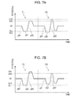
- the drive signals that are shown in Figs. 7A and 7B are provided with a large dot drive pulse PL that forms large dots on a recording medium (landing target) such as recording paper by ejecting comparatively large ink droplets, and a small dot drive pulse PS that forms small dots on the recording medium by ejecting comparatively small ink droplets.
- Both drive pulses PL and PS are provided with expansion elements p81 and p91 that cause a pressure chamber to expand by changing from an intermediate potential VC (a potential that is halfway between a maximum potential and a minimum potential) to expansion potentials VLL and VLS, expansion retention elements p82 and p92 that retain the expanded pressure chamber for a set period of time by retaining the expansion potentials VLL and VLS, and contraction elements p83 and p93 that cause the expanded pressure chamber to contract by changing from the expansion potentials VLL and VLS to contraction potentials VHL and VHS.
- expansion elements p81 and p91 that cause a pressure chamber to expand by changing from an intermediate potential VC (a potential that is halfway between a maximum potential and a minimum potential) to expansion potentials VLL and VLS
- expansion retention elements p82 and p92 that retain the expanded pressure chamber for a set period of time by retaining the expansion potentials VLL and VLS
- contraction elements p83 and p93 that cause the expanded pressure chamber to contract by changing from the expansion potential
- each drive pulse is optimized for each recording head so that target ink droplets are ejected. More specifically, a difference in potential between the expansion potentials VLL and VLS and the contraction potentials VHL and VHS is adjusted for each recording head. For example, in the drive signal that is shown as an example in Fig. 7A , a difference in potential (a maximum difference in potential) between the expansion potential VLS and the contraction potential VHS of the small dot drive pulse PS is set to be greater than a difference in potential (a maximum difference in potential) between the expansion potential VLL and the contraction potential VHL of the large dot drive pulse PL. On the other hand, in the drive signal that is shown as an example in Fig.
- a difference in potential (a maximum difference in potential) between an expansion potential VLL' and a contraction potential VHL' of a large dot drive pulse PL' is set to be greater than a difference in potential (a maximum difference in potential) between an expansion potential VLS' and a contraction potential VHS' of a small dot drive pulse PS'.
- the end terminal potentials of the large dot drive pulses PL and PL' and the start terminal potentials of the small dot drive pulses PS and PS' are made to be uniform at the intermediate potential VC, and connected.
- multi-gradation recording is performed by selecting a drive pulse from the drive pulses in the drive signal, and changing the size (or number) of dots that are formed in a predetermined region (a pixel region) of a recording medium (a landing target) such as recording paper.
- an amount of displacement an amount of deformation
- a drive voltage a difference in potential between the common electrode and the individual electrode
- a non-linear property more specifically, a hysteretic property.
- a linear region in which the piezoelectric properties have a linearity that is substantially close to a straight line is present in a certain region of the drive voltage.
- a linear region L (a portion that is enclosed by a dashed line in Fig. 6 ) is present in the vicinity of where the drive voltage is 0.
- a ratio of the amount of displacement with respect to the drive voltage is larger than non-linear regions other than the linear region L. Therefore, it is desirable to adjust the drive signal so that the piezoelectric body is driven in the linear region L that is in the piezoelectric properties thereof as often as possible.
- an apparatus that is configured so as to set the intermediate potential of the drive signal that is applied to the piezoelectric element to an optimum potential so as to suppress the influence of variations in the properties (the piezoelectric properties of the piezoelectric body layer) of the piezoelectric element of each recording head has been suggested (for example, refer to JP-A-2001-138551 ). That is, it is more convenient to adjust the intermediate potential than to adjust the potentials or inclinations of the constituent elements of the drive pulses.
- the expansion potential VLS of the small dot drive pulse PS matches a drive voltage V1 of the piezoelectric properties
- the contraction potential VHS matches a drive voltage V4
- the expansion potential VLL of the large dot drive pulse PL matches a drive voltage V2 that is higher than the drive voltage V1
- the contraction potential VHL matches a drive voltage V3 that is lower than the drive voltage V4.
- the intermediate potential VC is shifted to a low potential side.
- the small dot drive pulse PS is also completely shifted to a low potential side.
- the expansion potential VLL' of the large dot drive pulse PL' matches a drive voltage V1
- the contraction potential VHL' matches a drive voltage V4
- the expansion potential VLS' of the small dot drive pulse PS' matches a drive voltage V2 that is higher than the drive voltage V1
- the contraction potential VHS' matches a drive voltage V3 that is lower than the drive voltage V4.
- an intermediate potential VC' is shifted to a low potential side.
- the large dot drive pulse PL' is also completely shifted to a low potential side.
- the film thickness of the piezoelectric body layer is reduced, since the linear region L in the piezoelectric properties of the piezoelectric body layer becomes smaller, or in other words, since the non-linear region becomes larger, it becomes more likely that a range of the drive voltage that is used by other drive pulses will match the non-linear region, and therefore, deviation of ejecting properties such as that mentioned above becomes significant.
- the amount of displacement of the piezoelectric body layer itself is reduced.
- the piezoelectric body layer (piezoelectric element) is driven in a region that is shifted from the linear region L in which the ratio of the amount of displacement with respect to the drive voltage is large, there is a concern that it will not be possible to apply a sufficient pressure fluctuation to the ink inside the pressure chamber.
- An advantage of some aspects of the invention is to provide a liquid ejecting head that is capable of ejecting liquid droplets with optimum conditions that match the piezoelectric properties of a piezoelectric body, a driving method for the liquid ejecting head, a liquid ejecting apparatus that is provided with the liquid ejecting head, and a driving method for the liquid ejecting apparatus.
- a liquid ejecting apparatus of an aspect of the present invention includes a liquid ejecting head that has a piezoelectric body that deforms due to a drive signal being applied thereto, and is capable of ejecting liquid droplets from nozzles by bringing about a pressure fluctuation in a liquid inside a pressure chamber by using the deformation of the piezoelectric body, and a drive signal generator that generates the drive signal.
- the drive signal includes a first drive pulse that causes liquid droplets to be ejected from the nozzles and a second drive pulse that causes liquid droplets of a different size to those of the first drive pulse to be ejected from the nozzles, the first drive pulse and the second drive pulse have at least an expansion element that causes the pressure chamber to expand by changing from a standard potential, which is a standard for changes in potential, to an expansion potential, and a contraction element that causes the expanded pressure chamber to contract by changing from a potential that is on an expansion potential side of the standard potential to a contraction potential that exceeds the standard potential thereby ejecting the liquid, and an initiation potential of the contraction element of the first drive pulse and an initiation potential of the contraction element of the second drive pulse are made to be uniform at the same potential.
- the drive signal include a third drive pulse that causes liquid droplets of a different size to those of the first drive pulse and the second drive pulse to be ejected from the nozzles
- the third drive pulse have at least an expansion element that causes the pressure chamber to expand by changing from a standard potential, which is a standard for changes in potential, to an expansion potential, and a contraction element that causes the expanded pressure chamber to contract by changing from a potential that is on an expansion potential side of the standard potential to a contraction potential that exceeds the standard potential thereby ejecting the liquid, and an initiation potential of the contraction element of the third drive pulse be made to be uniform at the same potential as the initiation potential of the contraction element of the first drive pulse and the initiation potential of the contraction element of the second drive pulse.
- the third drive pulse cause liquid droplets that are smaller than those of the first drive pulse and larger than those of the second drive pulse to be ejected from the nozzles.
- the drive signal include a third drive pulse that causes liquid droplets of the same size as those of either the first drive pulse or the second drive pulse to be ejected from the nozzles
- the third drive pulse have at least an expansion element that causes the pressure chamber to expand by changing from a standard potential, which is a standard for changes in potential, to an expansion potential, and a contraction element that causes the expanded pressure chamber to contract by changing from a potential that is on an expansion potential side of the standard potential to a contraction potential that exceeds the standard potential thereby ejecting the liquid, and an initiation potential of the contraction element of the third drive pulse be made to be uniform at the same potential as the initiation potential of the contraction element of the first drive pulse and the initiation potential of the contraction element of the second drive pulse.
- the piezoelectric body be formed in a film-shape in which crystal is preferentially oriented.
- the aspect of the present invention it is possible to match both the initiation potential of the contraction element of the first drive pulse and the initiation potential of the contraction element of the second drive pulse with an intended drive voltage in the piezoelectric properties of the piezoelectric body. As a result of this, it is possible to make ejecting properties of ink droplets that are ejected from the nozzles using both drive pulses optimal properties that match the piezoelectric properties of the piezoelectric body.
- the initiation potentials of the contraction elements are made to be uniform in cases in which the standard potential (an intermediate potential of one drive pulse) is increased or decreased in order to adjust the amount of liquid droplets that are ejected using one drive pulse, it is possible to suppress a circumstance in which the driving of the piezoelectric body using each drive pulse deviates from optimum driving conditions. As a result of this, it is possible to suppress a circumstance in which the liquid droplets that are ejected using both drive pulses are ejected with conditions that deviate from optimal conditions.
- the expansion element in both the first drive pulse and the second drive pulse can use the maximum amount of a linear region in which the ratio of the amount of displacement with respect to the drive voltage is large, it is possible to eject liquid droplets with high efficiency. Therefore, it is possible to keep a ratio of changes in potential due to the contraction elements down.
- an ink jet type recording apparatus (hereinafter, referred to as a printer 1) is used as an example of a liquid ejecting apparatus of the present invention.
- Fig. 1 is a block diagram that describes an electrical configuration of a printer 1 and Fig. 2 is a perspective view that describes an internal configuration of the printer 1.
- An external apparatus 2 is for example, an electronic device such as a computer, a digital camera, a cellular phone, or a mobile data terminal device.
- the external apparatus 2 is electrically connected to the printer 1 with either a wired or wireless connection, and sends printing data that depends on an image or text to the printer 1 in order to print the image or the like on a recording medium S such as recording paper in the printer 1.
- the printer 1 of the present embodiment includes a printing engine 13 such as a paper delivery mechanism 3, a carriage movement mechanism 4, a linear encoder 5, and a recording head 6, and a printer controller 7.
- the recording head 6 is attached to a bottom surface side of a carriage 16 on which ink cartridges 17 (liquid supply sources) are mounted. Further, the carriage 16 is configured to be capable of reciprocating movement along a guide rod 18 using the carriage movement mechanism 4. That is, the printer 1 sequentially transports the recording medium S (a kind of landing target) such as recording paper using the paper delivery mechanism 3, and lands ink on the recording medium S by ejecting the ink from nozzles 25 (refer to Fig.
- the recording medium S a kind of landing target
- the printer controller 7 is a control unit that performs the control of the various units of the printer 1.
- the printer controller 7 in the present embodiment includes an interface (I/F) unit 8, a control unit 9, a storage unit 10 and a drive signal generator 11 (corresponding to the drive signal generator of the present invention).
- the interface unit 8 performs the transmission and reception of status data of the printer 1 when printing data or printing commands are sent from the external apparatus 2 to the printer 1, status information of the printer 1 is output to the external apparatus 2 or the like.
- the control unit 9 is an arithmetic processing unit for performing overall control of the printer 1.
- the storage unit 10 is an element that stores programs of the control unit 9 and data that is used in various controls, and includes ROM, RAM and NVRAM (non-volatile storage elements).
- the control unit 9 controls each unit according to the programs that are stored in the storage unit 10.
- the control unit 9 in the present embodiment generates ejection data, which indicates from which nozzles 25 and at what timing to eject ink during a recording action, on the basis of image data from the external apparatus 2, and sends the ejection data to a head control unit 15 of the recording head 6.
- the drive signal generator 11 generates an analog signal on the basis of waveform data that is related to a waveform of a drive signal, and generates a drive signal COM such as that shown in Figs. 4A and 4B by amplifying the signal.
- the printing engine 13 is provided with the paper delivery mechanism 3, the carriage movement mechanism 4, the linear encoder 5, the recording head 6 and the like.
- the carriage movement mechanism 4 is formed from the carriage 16 to which the recording head 6 is attached as a type of liquid ejecting head, a drive motor (for example, a DC motor), which causes the carriage 16 to travel using a timing belt or the like, and the like (neither of which are shown in the drawings), and causes the recording head 6 that is mounted to the carriage 16 to move in a main scanning direction.
- the paper delivery mechanism 3 is formed from a paper delivery motor, a paper delivery roller and the like, and performs sub scanning by sequentially sending recording medium S out onto a platen.
- the linear encoder 5 outputs an encoder pulse that depends on a scanning position of the recording head 6 that is mounted to the carriage 16 to the printer controller 7 as position information in the main scanning direction.
- the control unit 9 of the printer controller 7 can ascertain the scanning position (current position) of the recording head 6 on the basis of the encoder pulse that is received from the linear encoder 5 side.
- the control unit 9 generates a timing signal (latch signal), which stipulates a generation timing of a drive signal COM (to be described later), on the basis of the encoder pulse.
- Fig. 3 is a main portion cross-sectional view that describes an internal configuration of the recording head 6.
- the recording head 6 of the present embodiment is configured from a nozzle plate 21, a flow channel substrate 22, a piezoelectric element 23 and the like, and is attached to a case 24 in a state in which these members are laminated.
- the nozzle plate 21 is a plate-shaped member in which a plurality of nozzles 25 are provided in row form in an open manner with a predetermined pitch.
- two nozzle rows which are configured from the plurality of nozzles 25 that are arranged in parallel, are arranged in parallel in the nozzle plate 21.
- the flow channel substrate 22 is a plate material that is formed from a silicon monocrystalline substrate or the like.
- a plurality of pressure chambers 26 are formed in the flow channel substrate 22 lined up in a nozzle row direction.
- Each pressure chamber 26 is provided on a one-to-one basis to correspond to each nozzle 25 of the nozzle plate 21. That is, the formation pitch of each pressure chamber 26 corresponds to the formation pitch of the nozzles 25.
- two pressure chamber rows are provided to correspond to the two nozzle rows.
- reservoirs 30 that penetrate through the flow channel substrate 22 are formed along a parallel arrangement direction of the pressure chambers 26 in a region that is separated from a side that is opposite a communication side of the nozzle 25 with the pressure chamber 26.
- the reservoir 30 is a hollow part that is common to each pressure chamber 26 that belongs to the same pressure chamber row.
- the reservoirs 30 and each pressure chamber 26 are respectively in communication with one another via ink supply openings 27 that are formed with a width that is narrower than that of the pressure chambers 26. Additionally, ink from an ink cartridge 17 side is introduced into the reservoirs 30 through ink supply channels 31 of the case 24.
- the nozzle plate 21 is joined to a bottom surface (a surface that is opposite a piezoelectric element 23 side) of the flow channel substrate 22 using an adhesive, a heat welding film or the like.
- the nozzle plate 21 is a plate material in which the plurality of nozzles 25 are provided in row form in an open manner with a predetermined pitch.
- a nozzle row is configured by lining up 360 nozzles 25 at a pitch that corresponds to 360 dpi.
- Each nozzle 25 is in communication with the pressure chamber 26 at an end part of a side that is opposite the ink supply opening 27.
- the nozzle plate 21 is for example, formed from glass ceramics, a silicon monocrystalline substrate, stainless steel or the like.
- a total of two nozzle rows are provided, and a liquid flow channel that corresponds to each nozzle row is provided in a bilaterally symmetrical manner with the nozzle 25 side on the inside thereof.
- the piezoelectric element 23 is formed on an upper surface of a side that is opposite a nozzle plate 21 side of the flow channel substrate 22 via an elastic film 33. That is, an opening of an upper part of each pressure chamber 26 is blocked by the elastic film 33, and the piezoelectric element 23 is further formed thereon.
- the piezoelectric element 23 is formed by sequentially laminating a metal lower electrode film, a piezoelectric body layer (a piezoelectric body film) in which a piezoelectric body is formed in film-shape, and an upper electrode film (none of which are shown in the drawings) that is formed from metal. It is preferable that crystal be oriented as the piezoelectric body layer.
- a piezoelectric body layer that is used is one in which crystal is oriented by formation using a so-called sol-gel method that obtains a piezoelectric body layer that is formed from a metal oxide by applying and drying, then gelatinizing a so-called sol in which a metal organic material has been dissolved or dispersed in a catalyst, and further firing the product at a high temperature.
- a lead zirconate titanate material is preferable as the material of the piezoelectric body layer in a case of use in an ink jet type recording head.
- the film formation method of the piezoelectric body layer is not particularly limited, and for example, the piezoelectric body layer may be formed by a sputtering method.
- the film formation method may use a method that grows crystals in an aqueous alkali solution at a low temperature using a high pressure treatment method after forming a lead zirconate titanate precursor film using a sol-gel method, a sputtering method or the like.
- crystals are preferentially oriented, and in the present embodiment, crystals are formed in pillar form in the piezoelectric body layer.
- preferential orientation refers to a state in which a specific crystal surface is arranged in a substantially constant direction rather than the orientation direction of crystals being disordered.
- a thin film with pillar-shaped crystals refers a state in which a thin film is formed by aggregation of substantially cylindrical crystals are formed by aggregation over a surface direction in a state in which the central axes thereof are substantially uniform in a thickness direction.
- a thin film that is formed by preferentially oriented granular crystals may also be used.
- the thickness of a piezoelectric body layer that is produced with this kind of a thin film step is generally 0.5 to 5 ⁇ m.
- a piezoelectric body layer (a piezoelectric element 23) that is formed in this manner deforms due to the drive signal COM being applied thereto through a wiring member 41. More specifically, if a constant common potential is applied to a common electrode, and an oscillatory waveform is applied to an individual electrode, an electrical field that depends on a difference in potential is brought about between the two electrodes. The piezoelectric body layer bends and deforms depending on the intensity of the electrical field.
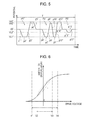
- Fig. 6 shows an example of piezoelectric properties of the piezoelectric body layer. Additionally, the horizontal axis of Fig.
- FIG. 6 represents a drive voltage (a difference in potential between the upper electrode film and the lower electrode film) that is applied to the piezoelectric body layer, and the vertical axis thereof represents an amount of displacement from a standard position of the piezoelectric body layer.
- the vertical axis thereof represents an amount of displacement from a standard position of the piezoelectric body layer.
- Regions of drive voltages that are further on the negative side or the positive side than the linear region L are non-linear regions in which the ratio of the amount of displacement with respect to the drive voltage becomes gradually smaller.
- the piezoelectric body layer that is, the piezoelectric element 23 bends and deforms depending on piezoelectric properties such as those mentioned above. That is, the higher the drive voltage (an application voltage) is set, the more a central portion of the piezoelectric body layer bends toward a side that approaches the nozzle plate 21, and deforms the elastic film 33 so as to reduce the capacity of the pressure chamber 26. On the other hand, the lower the drive voltage is set, the more a central portion of the piezoelectric body layer bends toward a side that becomes separated from the nozzle plate 21, and deforms the elastic film 33 so as to increase the capacity of the pressure chamber 26.
- the recording head 6 has a latch circuit 36, a decoder 37, a switch 38, and the piezoelectric element 23.
- the latch circuit 36, the decoder 37 and the switch 38 configure the head control unit 15, and the head control unit 15 is provided for each piezoelectric element 23, that is for each nozzle 25.
- the latch circuit 36 latches ejection data on the basis of print data.
- the ejection data is data that controls ejection and non-ejection of ink from each nozzle 25.
- the decoder 37 outputs a switch control signal that controls the switch 38 on the basis of the ejection data that is latched by the latch circuit 36.
- the switch control signal that is output from the decoder 37 is input to the switch 38.
- the switch 38 is a switch that is turned on and off depending on the switch control signal.
- Fig. 4A is a waveform chart that describes a configuration of a drive signal COM (an oscillatory waveform). Additionally, in Fig. 4 , the vertical axis represents potential, and the horizontal axis represents time.
- a unit period T which is a repeating period of the drive signal COM, corresponds to a period of time in which the nozzle 25 moves by a distance that corresponds to a width of a pixel, which is a constitutional unit of an image.
- the drive signals COM are generated depending on a latch signal, which is a timing signal that is generated on the basis of an encoder pulse that depends on the scanning position of the recording head 6.
- the drive signal COM is a signal that is generated at a period that is stipulated by the latch signal.
- the printer 1 in the present embodiment is capable of multi-gradation recording that forms dots of different sizes on the recording medium S, and in the present embodiment, is configured to be capable of a recording action with relatively large dots and relatively small dots. That is, the drive signal COM is a signal that generates a first drive pulse P1 that causes ink droplets to be ejected from the nozzles 25 and a second drive pulse P2 that causes ink droplets that are smaller than those of the first drive pulse P1 to be ejected from the nozzles 25 in this order.
- the first drive pulse P1, the second drive pulse P2 or both will be applied to the piezoelectric body layer.
- the first drive pulse P1 is configured from a first expansion element p1, a first expansion retention element p2, a first contraction element p3, a first contraction retention element p4 and a first expansion reversion element p5.
- the first expansion element p1 is an element that causes the pressure chamber 26 to expand from a standard capacity by changing from a standard potential VB, which is a standard for changes in potential, to a first expansion potential VL1 (the lowest potential).
- the first expansion retention element p2 is an element that retains the expanded pressure chamber 26 for a set period of time by retaining the first expansion potential VL1.
- the first contraction element p3 is an element that causes the expanded pressure chamber 26 to contract by changing from the first expansion potential VL1 to a first contraction potential VH2 (in the present embodiment, a potential that is higher than the standard potential VB, but lower than a second contraction potential VH1 (the highest potential)) that differs from the standard potential, thereby causing ink to be ejected.
- the first contraction retention element p4 is an element that retains the contracted pressure chamber 26 for a set period of time by retaining the first contraction potential VH2.
- the first expansion reversion element p5 is an element that causes the contracted pressure chamber 26 to revert to the standard capacity by changing from the first contraction potential VH2 to the standard potential VB.
- first drive pulse P1 When this kind of first drive pulse P1 is applied to a piezoelectric element 23, ink droplets that are larger than those of the second drive pulse P2 are ejected from the nozzle 25. More specifically, firstly, when the first expansion element p1 is applied, a meniscus that is exposed in the nozzle 25 is drawn in toward the pressure chamber 26 side. This state is retained by the first expansion retention element p2. Subsequently, when the first contraction element p3 is applied, the pressure chamber 26 is contracted suddenly, and the pressure of ink inside the pressure chamber 26 is increased. As a result of this, a relatively large amount of ink droplets are ejected from the nozzle 25. Thereafter, the pressure chamber 26 is reverted to the standard capacity by sequentially applying the first contraction retention element p4 and the first expansion reversion element p5.
- the second drive pulse P2 is configured from a second expansion element p6, a second expansion retention element p7, a second contraction element p8, a second contraction retention element p9, a second reexpansion element p10, a second reexpansion retention element p11 and a second contraction reversion element p12.
- the second expansion element p6 is an element that causes a pressure chamber 26 to expand from a standard capacity by changing from a standard potential VB, which is a standard for changes in potential, to a second expansion potential VL1 (the lowest potential) that is the same potential as the first expansion potential VL1.
- the second expansion retention element p7 is an element that retains the expanded pressure chamber 26 for a set period of time by retaining the second expansion potential VL1.
- the second contraction element p8 is an element that causes the expanded pressure chamber 26 to contract by changing from the second expansion potential VL1 to a second contraction potential VH1 (the highest potential), thereby causing ink to be ejected.
- the second contraction retention element p9 is an element that retains the contracted pressure chamber 26 for a set period of time by retaining the second contraction potential VH1.
- the second reexpansion element p10 is an element that causes the contracted pressure chamber 26 to expand again by changing from the second contraction potential VH1 to a second reexpansion potential VL2 that is lower than the standard potential VB, but higher than the second expansion potential VL1.
- the second reexpansion retention element p11 is an element that retains the expanded pressure chamber 26 for a set period of time by retaining the second reexpansion potential VL2.
- the second contraction reversion element p12 is an element that causes the expanded pressure chamber 26 to revert to the standard capacity by changing from the second reexpansion potential VL2 to the standard potential VB.
- the pressure chamber 26 expands again, and the meniscus is drawn in in a direction that is opposite a direction in which the ink has a tendency to extend. As a result of this, it becomes likely that a tip portion of an ink pillar will be cut off, and a relatively small droplet is ejected. Thereafter, the pressure chamber 26 is reverted to the standard capacity by sequentially applying the second reexpansion retention element p11 and the second contraction reversion element p12.
- a difference in potential of the second contraction element p8 in the second drive pulse P2 (a difference in potential between the second expansion potential VL1 and the second contraction potential VH1) is set so as to be larger than a difference in potential of the first contraction element p3 in the first drive pulse P1 (a difference in potential between the first expansion potential VL1 and the first contraction potential VH2).
- the VL1, which is the first expansion potential of the first drive pulse P1 and an initiation potential of the first contraction element p3 and the VL1, which is the second expansion potential of the second drive pulse P2 and an initiation potential of the second contraction element p8, are made to be uniform at the same potential.
- the standard potential VB is made to be uniform with an intermediate potential (an intermediate potential of the second expansion potential VL1 and the second contraction potential VH1) of the second drive pulse P2.
- the expansion potentials VL1 (the initiation potentials VL1 of the contraction elements p3 and p8 that cause ink to be ejected) of both of the drive pulses P1 and P2 are made to match the intended drive voltage V1 in the piezoelectric properties.
- the drive voltage V1 is a value in the piezoelectric properties that is within an ideal range (not limited to the linear region L) that is capable of efficiently expanding and contracting the pressure chamber 26 as quickly as possible with both of the drive pulses P1 and P2.
- the piezoelectric properties of the piezoelectric body layer are not limited to the properties that are shown in Fig. 6 , and various properties are possible, but regardless of the properties that are used, the expansion potentials VL1 of both of the drive pulses P1 and P2, that is, the initiation potentials VL1 of the contraction elements p3 and p8 that cause ink to be ejected, are made to match the intended drive voltage in the piezoelectric properties.
- the difference in potential of the second contraction element p8 of the second drive pulse P2 is set to be greater than the difference in potential of the first contraction element p3 of the first drive pulse P1, but the drive signal COM is not limited thereto.
- the difference in potential of the first contraction element p3' of the first drive pulse P1' is set to be greater than the difference in potential of the second contraction element p8' of the second drive pulse P2'.
- an amount of ink droplets that is ejected using the first drive pulse P1' is also greater than an amount of ink droplets that is ejected using the second drive pulse P2' in the drive signal COM that is shown in Fig. 4B .
- the first drive pulse P1' is configured from a first expansion element p1', a first expansion retention element p2', a first contraction element p3', a first contraction retention element p4' and a first expansion reversion element p5'.
- the first expansion element p1' is an element that causes a pressure chamber 26 to expand from a standard capacity by changing from a standard potential VB', which is a standard for changes in potential, to a first expansion potential VL1' (the lowest potential).
- the first expansion retention element p2' is an element that retains the expanded pressure chamber 26 for a set period of time by retaining the first expansion potential VL1'.
- the first contraction element p3' is an element that causes the expanded pressure chamber 26 to contract by changing from the first expansion potential VL1' to a first contraction potential VH1' (the highest potential) that differs from the standard potential, thereby causing ink to be ejected.
- the first contraction retention element p4' is an element that retains the contracted pressure chamber 26 for a set period of time by retaining the first contraction potential VH1'.
- the first expansion reversion element p5' is an element that causes the contracted pressure chamber 26 to revert to the standard capacity by changing from the first contraction potential VH1' to the standard potential VB'.
- the second drive pulse P2' is configured from a second expansion element p6', a second expansion retention element p7', a second contraction element p8', a second contraction retention element p9', a second reexpansion element p10', a second reexpansion retention element p11' and a second contraction reversion element p12'.
- the second expansion element p6' is an element that causes a pressure chamber 26 to expand from a standard capacity by changing from a standard potential VB', which is a standard for changes in potential, to a second expansion potential VL1' (the lowest potential) that is the same potential as the first expansion potential VL1'.
- the second expansion retention element p7' is an element that retains the expanded pressure chamber 26 for a set period of time by retaining the second expansion potential VL1'.
- the second contraction element p8' is an element that causes the expanded pressure chamber 26 to contract by changing from the second expansion potential VL1' to a second contraction potential VH2' that is higher than the standard potential VB', but lower than the first contraction potential VH1' (the highest potential), thereby causing ink to be ejected.
- the second contraction retention element p9' is an element that retains the contracted pressure chamber 26 for a set period of time by retaining the second contraction potential VH2'.
- the second reexpansion element p10' is an element that causes the contracted pressure chamber 26 to expand again by changing from the second contraction potential VH2' to a second reexpansion potential VL2' that is lower than the standard potential VB', but higher than the second expansion potential VL1'.
- the second reexpansion retention element p11' is an element that retains the expanded pressure chamber 26 for a set period of time by retaining the second reexpansion potential VL2'.
- the second contraction reversion element p12' is an element that causes the expanded pressure chamber 26 to revert to the standard capacity by changing from the second reexpansion potential VL2' to the standard potential VB'.
- the standard potential VB' is made to be uniform with an intermediate potential (an intermediate potential of the first expansion potential VL1' and the first contraction potential VH1') of the first drive pulse P1'.
- the expansion potentials VL1' of both of the drive pulses P1' and P2' that is, the initiation potentials VL1' of the contraction elements p3' and p8' that cause ink to be ejected, are also made to match the intended drive voltage in the piezoelectric properties of the piezoelectric body layer.
- the ejecting properties of ink droplets that are ejected using both of the drive pulses P1' and P2' to optimal properties that match the piezoelectric properties of the piezoelectric body.
- the configuration of the drive signal COM (the drive pulses) is not limited to that mentioned above, and it is possible to adopt various configurations provided the initiation potential of the contraction elements that cause ink to be ejected are made to be uniform at the same potential.
- Fig. 5 shows a configuration of a drive signal COM in another embodiment.
- an amount of ink droplets that is ejected using the first drive pulse P1" is greater than an amount of ink droplets that is ejected using the second drive pulse P2".
- the drive signal COM is provided with an aperiodic pulse P3" after the second drive pulse P2' in the unit period T.
- a first drive pulse P1" of the present embodiment is configured from a first expansion element p1", a first expansion retention element p2", a first contraction element p3", a first contraction retention element p4" and a first expansion reversion element p5".
- the first expansion element p1" is an element that causes a pressure chamber 26 to expand from a standard capacity by changing from a standard potential VB", which is a standard for changes in potential, to a first expansion potential VL1" (the lowest potential).
- the first expansion retention element p2" is an element that retains the expanded pressure chamber 26 for a set period of time by retaining the first expansion potential VL1".
- the first contraction element p3" is an element that causes the expanded pressure chamber 26 to contract by changing from the first expansion potential VL1" to a first contraction potential VH1" (the highest potential) that differs from the standard potential, thereby causing ink to be ejected.
- the first contraction retention element p4" is an element that retains the contracted pressure chamber 26 for a set period of time by retaining the first contraction potential VH1".
- the first expansion reversion element p5" is an element that causes the contracted pressure chamber 26 to revert to the standard capacity by changing from the first contraction potential VH1" to the standard potential VB".
- the second drive pulse P2" is configured from a second expansion element p6", a second expansion retention element p7", a second contraction element p8", a second contraction retention element p9", a second reexpansion element p10", a second reexpansion retention element p11", a second recontraction element p12", a second recontraction retention element p13" and a second expansion reversion element p14".
- the second expansion element p6" is an element that causes a pressure chamber 26 to expand from a standard capacity by changing from a standard potential VB", which is a standard for changes in potential, to a second expansion potential VL1" (the lowest potential) that is the same potential as the first expansion potential VL1".
- the second expansion retention element p7" is an element that retains the expanded pressure chamber 26 for a set period of time by retaining the second expansion potential VL1".
- the second contraction element p8" is an element that causes the expanded pressure chamber 26 to contract by changing from the second expansion potential VL1" to a second contraction potential VH2" that is higher than the standard potential VB", but lower than the second contraction potential VH1" (the first contraction potential VH1"), thereby causing ink to be ejected.
- the second contraction retention element p9" is an element that retains the contracted pressure chamber 26 for a set period of time by retaining the second contraction potential VH2".
- the second reexpansion element p10" is an element that causes the contracted pressure chamber 26 to expand again by changing from the second contraction potential VH2" to a second reexpansion potential VL1".
- the second reexpansion retention element p11" is an element that retains a reexpanded pressure chamber 26 for a set period of time by retaining the second reexpansion potential VL1" for a set period of time.
- the second recontraction element p12" is an element that causes the expanded pressure chamber 26 to contract again by changing from the second reexpansion potential VL1" to a second recontraction potential VH1".
- the second recontraction retention element p13" is an element that retains a recontracted pressure chamber 26 for a set period of time by retaining the second recontraction potential VH1" for a set period of time.
- the second expansion reversion element p14" is an element that causes the contracted pressure chamber 26 to revert to the standard capacity by changing from the second recontraction potential VH1" to the standard potential VB".
- the aperiodic pulse P3" is a drive pulse that is set to a waveform that is capable of causing a meniscus to vibrate to a degree at which ink is not ejected from the nozzle 25 in order to suppress the thickening of ink in the nozzle 25. More specifically, the aperiodic pulse P3" is configured from an aperiodic expansion element p15", an aperiodic expansion retention element p16" and an aperiodic reversion element p17".
- the aperiodic expansion element p15" is an element that causes a pressure chamber 26 to expand from a standard capacity to a slightly larger aperiodic expansion capacity by changing from a standard potential VB", which is a standard for changes in potential, to an aperiodic expansion potential VL2" that is higher than the second expansion potential VL1".
- the aperiodic expansion retention element p16" is an element that retains the expanded pressure chamber 26 for a set period of time by retaining the aperiodic expansion potential VL2".
- the aperiodic reversion element p17" is an element that causes a pressure chamber 26 that has expanded to the aperiodic expansion capacity to revert to the standard capacity by changing from the aperiodic expansion potential VL2" to the standard potential VB".
- the initiation potentials VL1" of the contraction elements p3" and p8" that cause ink to be ejected which are the expansion potentials of the drive pulses P1" and P2" are also made to match the intended drive voltage.
- the ejecting properties of ink droplets that are ejected using both of the drive pulses P1" and P2" are also made to match the piezoelectric properties of the piezoelectric body.
- each drive pulse P1" and P2" it is possible to set other potentials in each drive pulse P1" and P2" as appropriate, provided the initiation potentials VL1 of the contraction elements p3" and p8", which are the expansion potentials, that cause ink to be ejected are made to be uniform.
- initiation potentials VL1 of the contraction elements p3" and p8" which are the expansion potentials, that cause ink to be ejected are made to be uniform.
- a drive pulse of any configuration may be used as long as the drive pulse is provided with an expansion element that causes a pressure chamber 26 to expand by changing from the standard potential to an expansion potential and a contraction element that causes a pressure chamber 26 to contract, thereby ejecting ink and is capable of causing ink to be ejected from a nozzle 25.
- the number of drive pulses that are included in the drive signal COM is not limited to two, and it is possible to include a plurality of drive pulses therein.
- a large dot drive pulse that causes ink that corresponds to large dots to be ejected a medium dot drive pulse that causes ink that corresponds to medium dots to be ejected
- a small dot drive pulse that causes ink that corresponds to small dots to be ejected in a unit period T of a drive signal COM.
- a drive signal COM since the size of the dots differs greatly, it is likely a range of changes in potential of the drive signal COM (a range from the highest potential to the lowest potential) differs for each drive pulse.
- the driving of the piezoelectric body by a single drive pulse was optimized by increasing or decreasing the standard potential (the intermediate potential), there was a tendency for driving of the piezoelectric body by other drive pulses to deviate from optimal driving conditions.
- the initiation potentials of the contraction elements that cause ink to be ejected are made to be uniform in each drive pulse, it is possible to suppress a circumstance in which driving of the piezoelectric body by other drive pulses deviates from optimal driving conditions.
- the first drive pulse as a large dot drive pulse and the second drive pulse as a small dot drive pulse.
- the medium dot drive pulse corresponds to the third drive pulse in the present invention.
- a drive signal COM that is provided with a pulse that is the same as the large dot drive pulse after a large dot drive pulse that causes ink that corresponds to large dots to be ejected, and a small dot drive pulse that causes ink that corresponds to small dots to be ejected. That is, it is possible to apply the present invention to a drive signal COM that is provided with two large dot drive pulses and one small dot drive pulse. In this case, in each of the abovementioned embodiments, it is also possible to use the first drive pulse as a large dot drive pulse, and use the second drive pulse as a small dot drive pulse.
- an ink jet recording apparatus 1 that is provided with an ink jet recording head 6 that is one type of liquid ejecting head has been described above, but it is also possible to apply the present invention to other liquid ejecting head that are configured to bring about pressure fluctuations in a pressure chamber by causing a piezoelectric body to deform, and driving methods for liquid ejecting heads.
- liquid ejecting apparatuses that are provided with color material ejecting heads that are used in the production of color filters such as liquid crystal displays, electrode material ejecting heads that are used in electrode formation such as organic EL (Electro Luminescence) displays, FED (Field Emission Displays) and the like, organic material ejecting heads that are used in the production of biochips (biotips) and the like, and driving method of liquid ejecting apparatuses.
- color material ejecting heads that are used in the production of color filters
- electrode material ejecting heads that are used in electrode formation such as organic EL (Electro Luminescence) displays, FED (Field Emission Displays) and the like
- organic material ejecting heads that are used in the production of biochips (biotips) and the like
- driving method of liquid ejecting apparatuses driving method of liquid ejecting apparatuses.
Landscapes
- Particle Formation And Scattering Control In Inkjet Printers (AREA)
Abstract

Description
- The present invention relates to a liquid ejecting head that causes liquid droplets to be ejected from nozzles by supplying a drive signal to a piezoelectric body, a driving method for the liquid ejecting head, a liquid ejecting apparatus that is provided with the liquid ejecting head, and a driving method for the liquid ejecting apparatus.
- A liquid ejecting apparatus is an apparatus that is provided with a liquid ejecting head that is capable of ejecting a liquid as liquid droplets from nozzles, and which ejects various kinds of liquids from the liquid ejecting head. For example, it is possible to include image recording apparatuses (hereinafter, referred to as printers) such as ink jet recording apparatuses that are provided with an ink jet recording head (hereinafter, referred to as a recording head), and perform recording by ejecting ink in liquid form as ink droplets from nozzles of the recording head, as representative examples of this kind of liquid ejecting apparatus. Further, in addition to the above, liquid ejecting apparatuses are used in the ejecting of various types of liquids such as coloring materials that are used in color filters for liquid crystal displays and the like, organic materials that are used in organic EL (Electro Luminescence) displays, and electrode materials that are used in electrode formation. Further, liquid ink is ejected in recording heads for image recording apparatuses, and solutions of the respective color materials of R (Red), G (Green) and B (Blue) are ejected in color material ejecting heads for display production apparatuses. In addition, a liquid electrode material is ejected in electrode material ejecting heads for electrode formation apparatuses, and solutions of living organic matter are ejected in living organic matter ejecting heads for chip production apparatuses.
- A recording head such as that mentioned above is provided with a piezoelectric element that brings about pressure fluctuations in ink inside a pressure chamber. The piezoelectric element has a common electrode that is common to a plurality of piezoelectric elements, an individual electrode that is patterned individually in each piezoelectric element, and a piezoelectric body layer (piezoelectric body film) that is interposed between these electrodes. A flexible cable is electrically connected to terminals of the common electrode and the individual electrode. When a drive signal (drive voltage) is supplied between the common electrode and the individual electrode through the flexible cable, an electrical field that depends on a difference in potential is brought about between the two electrodes. The piezoelectric element (piezoelectric body film) for example, bends and deforms depending on the intensity of the electrical field, and a pressure fluctuation is brought about in ink inside the pressure chamber. Further, the recording head ejects ink droplets from nozzles that penetrate through the pressure chamber by using the pressure fluctuation. Additionally, normally, a constant potential is applied to the common electrode, and an oscillatory waveform is applied to the individual electrode.
- In addition, the abovementioned drive signal may include a series of drive pulses with different waveforms. The drive pulses eject a corresponding size (amount) of ink droplets from the nozzles by being selectively applied to the piezoelectric element. For example, the drive signals that are shown in
Figs. 7A and 7B are provided with a large dot drive pulse PL that forms large dots on a recording medium (landing target) such as recording paper by ejecting comparatively large ink droplets, and a small dot drive pulse PS that forms small dots on the recording medium by ejecting comparatively small ink droplets. Both drive pulses PL and PS are provided with expansion elements p81 and p91 that cause a pressure chamber to expand by changing from an intermediate potential VC (a potential that is halfway between a maximum potential and a minimum potential) to expansion potentials VLL and VLS, expansion retention elements p82 and p92 that retain the expanded pressure chamber for a set period of time by retaining the expansion potentials VLL and VLS, and contraction elements p83 and p93 that cause the expanded pressure chamber to contract by changing from the expansion potentials VLL and VLS to contraction potentials VHL and VHS. - In addition, each drive pulse is optimized for each recording head so that target ink droplets are ejected. More specifically, a difference in potential between the expansion potentials VLL and VLS and the contraction potentials VHL and VHS is adjusted for each recording head. For example, in the drive signal that is shown as an example in
Fig. 7A , a difference in potential (a maximum difference in potential) between the expansion potential VLS and the contraction potential VHS of the small dot drive pulse PS is set to be greater than a difference in potential (a maximum difference in potential) between the expansion potential VLL and the contraction potential VHL of the large dot drive pulse PL. On the other hand, in the drive signal that is shown as an example inFig. 7B , a difference in potential (a maximum difference in potential) between an expansion potential VLL' and a contraction potential VHL' of a large dot drive pulse PL' is set to be greater than a difference in potential (a maximum difference in potential) between an expansion potential VLS' and a contraction potential VHS' of a small dot drive pulse PS'. Additionally, the end terminal potentials of the large dot drive pulses PL and PL' and the start terminal potentials of the small dot drive pulses PS and PS' are made to be uniform at the intermediate potential VC, and connected. In a printer that has this kind of drive signal, multi-gradation recording is performed by selecting a drive pulse from the drive pulses in the drive signal, and changing the size (or number) of dots that are formed in a predetermined region (a pixel region) of a recording medium (a landing target) such as recording paper. - Given that, with respect to the piezoelectric properties of the piezoelectric body layer (the piezoelectric body), it is known that an amount of displacement (an amount of deformation) with respect to a drive voltage (a difference in potential between the common electrode and the individual electrode) that is applied has a non-linear property (more specifically, a hysteretic property). In the piezoelectric properties of this kind of piezoelectric body layer, a linear region in which the piezoelectric properties have a linearity that is substantially close to a straight line is present in a certain region of the drive voltage. For example, in the piezoelectric properties of a piezoelectric body layer that is shown as an example in
Fig. 6 , a linear region L (a portion that is enclosed by a dashed line inFig. 6 ) is present in the vicinity of where the drive voltage is 0. In this linear region L, a ratio of the amount of displacement with respect to the drive voltage is larger than non-linear regions other than the linear region L. Therefore, it is desirable to adjust the drive signal so that the piezoelectric body is driven in the linear region L that is in the piezoelectric properties thereof as often as possible. - On the other hand, in the piezoelectric properties of this kind of piezoelectric body layer, there are circumstances in which the properties deviate from expected piezoelectric properties due to variation in the time of production and the like. When the piezoelectric properties of the piezoelectric body layer deviate, there is a concern that the ejecting properties of ink droplets that are ejected from the nozzles will deviate from the properties that are originally expected. Therefore, an apparatus that is configured so as to set the intermediate potential of the drive signal that is applied to the piezoelectric element to an optimum potential so as to suppress the influence of variations in the properties (the piezoelectric properties of the piezoelectric body layer) of the piezoelectric element of each recording head has been suggested (for example, refer to
JP-A-2001-138551 - However, in a drive signal that has two or more pulses in which the differences in potential between the expansion potential and the contraction potential differ, as a result of adjusting the intermediate potential in the abovementioned manner, there is a concern that one drive pulse will deviate from optimum conditions if another of the drive pulses is adjusted so as to match optimum conditions at which optimum ejection is performed. For example, in a case in which the piezoelectric body layer has piezoelectric properties such as those shown in
Fig. 6 , in the drive signal that is shown inFig. 7A , the expansion potential VLS of the small dot drive pulse PS matches a drive voltage V1 of the piezoelectric properties, the contraction potential VHS matches a drive voltage V4, the expansion potential VLL of the large dot drive pulse PL matches a drive voltage V2 that is higher than the drive voltage V1, and the contraction potential VHL matches a drive voltage V3 that is lower than the drive voltage V4. For example, in a case in which the potential of the large dot drive pulse PL is completely shifted to a low potential side in order to make the potential match a potential for ideal driving that aims to drive using the large dot drive pulse PL from this state, that is, driving in which efficiency is as favorable as possible in consideration of a balance between the amount of expansion and the amount of contraction of the pressure chamber, the intermediate potential VC is shifted to a low potential side. As a result of this, the small dot drive pulse PS is also completely shifted to a low potential side. This results in the expansion potential VLS of the small dot drive pulse PS being shifted to a region in which the inclination of the piezoelectric properties is smaller than at V1 (a region in which a ratio of the amount of displacement with respect to the drive voltage is small), and the contraction potential VHS being shifted to a region in which the inclination of the piezoelectric properties is larger than at V4 (a region in which a ratio of the amount of displacement with respect to the drive voltage is large), and therefore driving due to the small dot drive pulse PS deviates from the ideal driving that is aimed for. That is, if the ejecting properties of ink droplets that are ejected from the nozzles using the large dot drive pulse PL are made to match intended properties, there is a concern that the ejecting properties of ink droplets that are ejected from the nozzles using the small dot drive pulse PS will deviate from the properties that are originally intended. - In addition, in the drive signal that is shown in
Fig. 7B , the expansion potential VLL' of the large dot drive pulse PL' matches a drive voltage V1, the contraction potential VHL' matches a drive voltage V4, the expansion potential VLS' of the small dot drive pulse PS' matches a drive voltage V2 that is higher than the drive voltage V1, and the contraction potential VHS' matches a drive voltage V3 that is lower than the drive voltage V4. For example, in a case in which the potential of the small dot drive pulse PS' is completely shifted to a low potential side in order to make the potential match a potential for ideal driving that aims to drive using the small dot drive pulse PS' from this state, an intermediate potential VC' is shifted to a low potential side. As a result of this, the large dot drive pulse PL' is also completely shifted to a low potential side. This results in the expansion potential VLL' of the large dot drive pulse PL' being shifted to a region in which the inclination of the piezoelectric properties is smaller than at V1 (a region in which a ratio of the amount of displacement with respect to the drive voltage is small), and the contraction potential VHL' being shifted to a region in which the inclination of the piezoelectric properties is larger than at V4 (a region in which a ratio of the amount of displacement with respect to the drive voltage is large), and therefore driving due to the large dot drive pulse PL' deviates from the ideal driving that is aimed for. That is, if the ejecting properties of ink droplets that are ejected from the nozzles using the small dot drive pulse PS' are made to match intended properties, there is a concern that the ejecting properties of ink droplets that are ejected from the nozzles using the large dot drive pulse PL' will deviate from the properties that are originally intended. - In this manner, in the related art, in a drive signal that has two or more different pulses, it is not possible to eject liquid droplets with optimal conditions that match the individual piezoelectric properties of the piezoelectric body layer in all of the pulses. In particular, in recent years, the thinning of piezoelectric body layers (piezoelectric bodies) has been progressing along with the miniaturization of recording heads. If the film thickness of the piezoelectric body layer is reduced, since the linear region L in the piezoelectric properties of the piezoelectric body layer becomes smaller, or in other words, since the non-linear region becomes larger, it becomes more likely that a range of the drive voltage that is used by other drive pulses will match the non-linear region, and therefore, deviation of ejecting properties such as that mentioned above becomes significant. In addition, as thinning of the piezoelectric body layer progresses, the amount of displacement of the piezoelectric body layer itself is reduced. Therefore, if the piezoelectric body layer (piezoelectric element) is driven in a region that is shifted from the linear region L in which the ratio of the amount of displacement with respect to the drive voltage is large, there is a concern that it will not be possible to apply a sufficient pressure fluctuation to the ink inside the pressure chamber.
- An advantage of some aspects of the invention is to provide a liquid ejecting head that is capable of ejecting liquid droplets with optimum conditions that match the piezoelectric properties of a piezoelectric body, a driving method for the liquid ejecting head, a liquid ejecting apparatus that is provided with the liquid ejecting head, and a driving method for the liquid ejecting apparatus.
- A liquid ejecting apparatus of an aspect of the present invention includes a liquid ejecting head that has a piezoelectric body that deforms due to a drive signal being applied thereto, and is capable of ejecting liquid droplets from nozzles by bringing about a pressure fluctuation in a liquid inside a pressure chamber by using the deformation of the piezoelectric body, and a drive signal generator that generates the drive signal. The drive signal includes a first drive pulse that causes liquid droplets to be ejected from the nozzles and a second drive pulse that causes liquid droplets of a different size to those of the first drive pulse to be ejected from the nozzles, the first drive pulse and the second drive pulse have at least an expansion element that causes the pressure chamber to expand by changing from a standard potential, which is a standard for changes in potential, to an expansion potential, and a contraction element that causes the expanded pressure chamber to contract by changing from a potential that is on an expansion potential side of the standard potential to a contraction potential that exceeds the standard potential thereby ejecting the liquid, and an initiation potential of the contraction element of the first drive pulse and an initiation potential of the contraction element of the second drive pulse are made to be uniform at the same potential.
- In addition, in the abovementioned configuration, it is desirable that the drive signal include a third drive pulse that causes liquid droplets of a different size to those of the first drive pulse and the second drive pulse to be ejected from the nozzles, the third drive pulse have at least an expansion element that causes the pressure chamber to expand by changing from a standard potential, which is a standard for changes in potential, to an expansion potential, and a contraction element that causes the expanded pressure chamber to contract by changing from a potential that is on an expansion potential side of the standard potential to a contraction potential that exceeds the standard potential thereby ejecting the liquid, and an initiation potential of the contraction element of the third drive pulse be made to be uniform at the same potential as the initiation potential of the contraction element of the first drive pulse and the initiation potential of the contraction element of the second drive pulse.
- Furthermore, in the abovementioned configuration, it is desirable that the third drive pulse cause liquid droplets that are smaller than those of the first drive pulse and larger than those of the second drive pulse to be ejected from the nozzles.
- In addition, it is desirable that the drive signal include a third drive pulse that causes liquid droplets of the same size as those of either the first drive pulse or the second drive pulse to be ejected from the nozzles, the third drive pulse have at least an expansion element that causes the pressure chamber to expand by changing from a standard potential, which is a standard for changes in potential, to an expansion potential, and a contraction element that causes the expanded pressure chamber to contract by changing from a potential that is on an expansion potential side of the standard potential to a contraction potential that exceeds the standard potential thereby ejecting the liquid, and an initiation potential of the contraction element of the third drive pulse be made to be uniform at the same potential as the initiation potential of the contraction element of the first drive pulse and the initiation potential of the contraction element of the second drive pulse.
- Furthermore, in the abovementioned configuration, it is desirable that the piezoelectric body be formed in a film-shape in which crystal is preferentially oriented.
- According to the aspect of the present invention, it is possible to match both the initiation potential of the contraction element of the first drive pulse and the initiation potential of the contraction element of the second drive pulse with an intended drive voltage in the piezoelectric properties of the piezoelectric body. As a result of this, it is possible to make ejecting properties of ink droplets that are ejected from the nozzles using both drive pulses optimal properties that match the piezoelectric properties of the piezoelectric body. That is, since the initiation potentials of the contraction elements are made to be uniform in cases in which the standard potential (an intermediate potential of one drive pulse) is increased or decreased in order to adjust the amount of liquid droplets that are ejected using one drive pulse, it is possible to suppress a circumstance in which the driving of the piezoelectric body using each drive pulse deviates from optimum driving conditions. As a result of this, it is possible to suppress a circumstance in which the liquid droplets that are ejected using both drive pulses are ejected with conditions that deviate from optimal conditions. Furthermore, since the expansion element in both the first drive pulse and the second drive pulse can use the maximum amount of a linear region in which the ratio of the amount of displacement with respect to the drive voltage is large, it is possible to eject liquid droplets with high efficiency. Therefore, it is possible to keep a ratio of changes in potential due to the contraction elements down.
- Embodiments of the invention will now be described by way of example only with reference to the accompanying drawings, wherein like numbers reference like elements.
-
Fig. 1 is a block diagram that describes an electrical configuration of a printer. -
Fig. 2 is a perspective view that describes an internal configuration of a printer. -
Fig. 3 is a cross-sectional view that describes a configuration of a recording head. -
Figs. 4A and 4B are waveform charts that describe a configuration of a drive signal. -
Fig. 5 is a waveform chart that describes a configuration of a drive signal in another embodiment. -
Fig. 6 is a characteristic diagram that shows a relationship between a drive voltage and an amount of displacement of a piezoelectric body. -
Figs. 7A and 7B are schematic diagrams that describe a configuration of a drive signal of the related art. - Hereinafter, an embodiment for implementing the present invention will be described with reference to the appended drawings. Additionally, in the embodiments that will be described below, various limitations are given as preferred specific examples of the present invention, but the scope of the present invention is not limited to these aspects unless a feature that limits the present invention is specifically stated in the following description. In addition, in the following description, an ink jet type recording apparatus (hereinafter, referred to as a printer 1) is used as an example of a liquid ejecting apparatus of the present invention.
-
Fig. 1 is a block diagram that describes an electrical configuration of aprinter 1 andFig. 2 is a perspective view that describes an internal configuration of theprinter 1. Anexternal apparatus 2 is for example, an electronic device such as a computer, a digital camera, a cellular phone, or a mobile data terminal device. Theexternal apparatus 2 is electrically connected to theprinter 1 with either a wired or wireless connection, and sends printing data that depends on an image or text to theprinter 1 in order to print the image or the like on a recording medium S such as recording paper in theprinter 1. - The
printer 1 of the present embodiment includes aprinting engine 13 such as apaper delivery mechanism 3, acarriage movement mechanism 4, alinear encoder 5, and arecording head 6, and a printer controller 7. Therecording head 6 is attached to a bottom surface side of acarriage 16 on which ink cartridges 17 (liquid supply sources) are mounted. Further, thecarriage 16 is configured to be capable of reciprocating movement along aguide rod 18 using thecarriage movement mechanism 4. That is, theprinter 1 sequentially transports the recording medium S (a kind of landing target) such as recording paper using thepaper delivery mechanism 3, and lands ink on the recording medium S by ejecting the ink from nozzles 25 (refer toFig. 3 ) of therecording head 6 while relatively moving therecording head 6 with respect to the recording medium S in a width direction (a main scanning direction) of the recording medium S, thereby recording images or the like. Additionally, it is possible to adopt a configuration in which the ink cartridges are disposed on a main body side of the printer, and ink from the ink cartridges is delivered to a recording head side through supply tubes. - The printer controller 7 is a control unit that performs the control of the various units of the
printer 1. The printer controller 7 in the present embodiment includes an interface (I/F)unit 8, a control unit 9, astorage unit 10 and a drive signal generator 11 (corresponding to the drive signal generator of the present invention). Theinterface unit 8 performs the transmission and reception of status data of theprinter 1 when printing data or printing commands are sent from theexternal apparatus 2 to theprinter 1, status information of theprinter 1 is output to theexternal apparatus 2 or the like. The control unit 9 is an arithmetic processing unit for performing overall control of theprinter 1. Thestorage unit 10 is an element that stores programs of the control unit 9 and data that is used in various controls, and includes ROM, RAM and NVRAM (non-volatile storage elements). The control unit 9 controls each unit according to the programs that are stored in thestorage unit 10. In addition, the control unit 9 in the present embodiment generates ejection data, which indicates from which nozzles 25 and at what timing to eject ink during a recording action, on the basis of image data from theexternal apparatus 2, and sends the ejection data to ahead control unit 15 of therecording head 6. Thedrive signal generator 11 generates an analog signal on the basis of waveform data that is related to a waveform of a drive signal, and generates a drive signal COM such as that shown inFigs. 4A and 4B by amplifying the signal. - Next, the
printing engine 13 will be described. As shown inFig. 1 , theprinting engine 13 is provided with thepaper delivery mechanism 3, thecarriage movement mechanism 4, thelinear encoder 5, therecording head 6 and the like. Thecarriage movement mechanism 4 is formed from thecarriage 16 to which therecording head 6 is attached as a type of liquid ejecting head, a drive motor (for example, a DC motor), which causes thecarriage 16 to travel using a timing belt or the like, and the like (neither of which are shown in the drawings), and causes therecording head 6 that is mounted to thecarriage 16 to move in a main scanning direction. Thepaper delivery mechanism 3 is formed from a paper delivery motor, a paper delivery roller and the like, and performs sub scanning by sequentially sending recording medium S out onto a platen. In addition, thelinear encoder 5 outputs an encoder pulse that depends on a scanning position of therecording head 6 that is mounted to thecarriage 16 to the printer controller 7 as position information in the main scanning direction. The control unit 9 of the printer controller 7 can ascertain the scanning position (current position) of therecording head 6 on the basis of the encoder pulse that is received from thelinear encoder 5 side. In addition, the control unit 9 generates a timing signal (latch signal), which stipulates a generation timing of a drive signal COM (to be described later), on the basis of the encoder pulse. -
Fig. 3 is a main portion cross-sectional view that describes an internal configuration of therecording head 6. Therecording head 6 of the present embodiment is configured from anozzle plate 21, aflow channel substrate 22, apiezoelectric element 23 and the like, and is attached to acase 24 in a state in which these members are laminated. Thenozzle plate 21 is a plate-shaped member in which a plurality ofnozzles 25 are provided in row form in an open manner with a predetermined pitch. In the present embodiment, two nozzle rows, which are configured from the plurality ofnozzles 25 that are arranged in parallel, are arranged in parallel in thenozzle plate 21. - The
flow channel substrate 22 is a plate material that is formed from a silicon monocrystalline substrate or the like. A plurality ofpressure chambers 26 are formed in theflow channel substrate 22 lined up in a nozzle row direction. Eachpressure chamber 26 is provided on a one-to-one basis to correspond to eachnozzle 25 of thenozzle plate 21. That is, the formation pitch of eachpressure chamber 26 corresponds to the formation pitch of thenozzles 25. In the present embodiment, two pressure chamber rows are provided to correspond to the two nozzle rows. In addition,reservoirs 30 that penetrate through theflow channel substrate 22 are formed along a parallel arrangement direction of thepressure chambers 26 in a region that is separated from a side that is opposite a communication side of thenozzle 25 with thepressure chamber 26. Thereservoir 30 is a hollow part that is common to eachpressure chamber 26 that belongs to the same pressure chamber row. Thereservoirs 30 and eachpressure chamber 26 are respectively in communication with one another viaink supply openings 27 that are formed with a width that is narrower than that of thepressure chambers 26. Additionally, ink from anink cartridge 17 side is introduced into thereservoirs 30 throughink supply channels 31 of thecase 24. - The
nozzle plate 21 is joined to a bottom surface (a surface that is opposite apiezoelectric element 23 side) of theflow channel substrate 22 using an adhesive, a heat welding film or the like. Thenozzle plate 21 is a plate material in which the plurality ofnozzles 25 are provided in row form in an open manner with a predetermined pitch. In the present embodiment, a nozzle row is configured by lining up 360nozzles 25 at a pitch that corresponds to 360 dpi. Eachnozzle 25 is in communication with thepressure chamber 26 at an end part of a side that is opposite theink supply opening 27. Additionally, thenozzle plate 21 is for example, formed from glass ceramics, a silicon monocrystalline substrate, stainless steel or the like. In therecording head 6 of the present embodiment, a total of two nozzle rows are provided, and a liquid flow channel that corresponds to each nozzle row is provided in a bilaterally symmetrical manner with thenozzle 25 side on the inside thereof. - The
piezoelectric element 23 is formed on an upper surface of a side that is opposite anozzle plate 21 side of theflow channel substrate 22 via anelastic film 33. That is, an opening of an upper part of eachpressure chamber 26 is blocked by theelastic film 33, and thepiezoelectric element 23 is further formed thereon. Thepiezoelectric element 23 is formed by sequentially laminating a metal lower electrode film, a piezoelectric body layer (a piezoelectric body film) in which a piezoelectric body is formed in film-shape, and an upper electrode film (none of which are shown in the drawings) that is formed from metal. It is preferable that crystal be oriented as the piezoelectric body layer. For example, in the present embodiment, a piezoelectric body layer that is used is one in which crystal is oriented by formation using a so-called sol-gel method that obtains a piezoelectric body layer that is formed from a metal oxide by applying and drying, then gelatinizing a so-called sol in which a metal organic material has been dissolved or dispersed in a catalyst, and further firing the product at a high temperature. A lead zirconate titanate material is preferable as the material of the piezoelectric body layer in a case of use in an ink jet type recording head. Additionally, the film formation method of the piezoelectric body layer is not particularly limited, and for example, the piezoelectric body layer may be formed by a sputtering method. In addition, the film formation method may use a method that grows crystals in an aqueous alkali solution at a low temperature using a high pressure treatment method after forming a lead zirconate titanate precursor film using a sol-gel method, a sputtering method or the like. - Regardless of the method used, in a piezoelectric body layer that is formed in this manner, different to so-called bulk piezoelectric bodies, crystals are preferentially oriented, and in the present embodiment, crystals are formed in pillar form in the piezoelectric body layer. Additionally, preferential orientation refers to a state in which a specific crystal surface is arranged in a substantially constant direction rather than the orientation direction of crystals being disordered. In addition, a thin film with pillar-shaped crystals refers a state in which a thin film is formed by aggregation of substantially cylindrical crystals are formed by aggregation over a surface direction in a state in which the central axes thereof are substantially uniform in a thickness direction. Naturally, a thin film that is formed by preferentially oriented granular crystals may also be used. Additionally, the thickness of a piezoelectric body layer that is produced with this kind of a thin film step is generally 0.5 to 5 µm.
- A piezoelectric body layer (a piezoelectric element 23) that is formed in this manner deforms due to the drive signal COM being applied thereto through a
wiring member 41. More specifically, if a constant common potential is applied to a common electrode, and an oscillatory waveform is applied to an individual electrode, an electrical field that depends on a difference in potential is brought about between the two electrodes. The piezoelectric body layer bends and deforms depending on the intensity of the electrical field.Fig. 6 shows an example of piezoelectric properties of the piezoelectric body layer. Additionally, the horizontal axis ofFig. 6 represents a drive voltage (a difference in potential between the upper electrode film and the lower electrode film) that is applied to the piezoelectric body layer, and the vertical axis thereof represents an amount of displacement from a standard position of the piezoelectric body layer. As shown inFig. 6 , in the piezoelectric properties of the piezoelectric body layer in the present embodiment, there is a linear region L in the vicinity of where the drive voltage is 0, in which the properties change in substantially linear form from partway through negative drive voltages to partway through positive drive voltages (a portion that is enclosed by a dashed line inFig. 6 ). Regions of drive voltages that are further on the negative side or the positive side than the linear region L are non-linear regions in which the ratio of the amount of displacement with respect to the drive voltage becomes gradually smaller. - The piezoelectric body layer, that is, the
piezoelectric element 23 bends and deforms depending on piezoelectric properties such as those mentioned above. That is, the higher the drive voltage (an application voltage) is set, the more a central portion of the piezoelectric body layer bends toward a side that approaches thenozzle plate 21, and deforms theelastic film 33 so as to reduce the capacity of thepressure chamber 26. On the other hand, the lower the drive voltage is set, the more a central portion of the piezoelectric body layer bends toward a side that becomes separated from thenozzle plate 21, and deforms theelastic film 33 so as to increase the capacity of thepressure chamber 26. In this manner, since the capacity of thepressure chamber 26 changes when thepiezoelectric element 23 is driven, the pressure of ink inside thepressure chamber 26 changes depending on this change. Further, it is possible to cause ink droplets to be ejected from thenozzles 25 by controlling this pressure change (pressure fluctuation) in the ink. - Next, an electrical configuration of the
recording head 6 will be described. - As shown in
Fig. 1 , therecording head 6 has alatch circuit 36, adecoder 37, aswitch 38, and thepiezoelectric element 23. Thelatch circuit 36, thedecoder 37 and theswitch 38 configure thehead control unit 15, and thehead control unit 15 is provided for eachpiezoelectric element 23, that is for eachnozzle 25. Thelatch circuit 36 latches ejection data on the basis of print data. The ejection data is data that controls ejection and non-ejection of ink from eachnozzle 25. Thedecoder 37 outputs a switch control signal that controls theswitch 38 on the basis of the ejection data that is latched by thelatch circuit 36. The switch control signal that is output from thedecoder 37 is input to theswitch 38. Theswitch 38 is a switch that is turned on and off depending on the switch control signal. -
Fig. 4A is a waveform chart that describes a configuration of a drive signal COM (an oscillatory waveform). Additionally, inFig. 4 , the vertical axis represents potential, and the horizontal axis represents time. In the present embodiment, when therecording head 6 performs the ejection of ink while moving relatively with respect to the recording medium S, a unit period T, which is a repeating period of the drive signal COM, corresponds to a period of time in which thenozzle 25 moves by a distance that corresponds to a width of a pixel, which is a constitutional unit of an image. The drive signals COM are generated depending on a latch signal, which is a timing signal that is generated on the basis of an encoder pulse that depends on the scanning position of therecording head 6. Therefore, the drive signal COM is a signal that is generated at a period that is stipulated by the latch signal. Theprinter 1 in the present embodiment is capable of multi-gradation recording that forms dots of different sizes on the recording medium S, and in the present embodiment, is configured to be capable of a recording action with relatively large dots and relatively small dots. That is, the drive signal COM is a signal that generates a first drive pulse P1 that causes ink droplets to be ejected from thenozzles 25 and a second drive pulse P2 that causes ink droplets that are smaller than those of the first drive pulse P1 to be ejected from thenozzles 25 in this order. Thus, depending on the printing data and the latching, either the first drive pulse P1, the second drive pulse P2 or both will be applied to the piezoelectric body layer. - The first drive pulse P1 is configured from a first expansion element p1, a first expansion retention element p2, a first contraction element p3, a first contraction retention element p4 and a first expansion reversion element p5. The first expansion element p1 is an element that causes the
pressure chamber 26 to expand from a standard capacity by changing from a standard potential VB, which is a standard for changes in potential, to a first expansion potential VL1 (the lowest potential). The first expansion retention element p2 is an element that retains the expandedpressure chamber 26 for a set period of time by retaining the first expansion potential VL1. The first contraction element p3 is an element that causes the expandedpressure chamber 26 to contract by changing from the first expansion potential VL1 to a first contraction potential VH2 (in the present embodiment, a potential that is higher than the standard potential VB, but lower than a second contraction potential VH1 (the highest potential)) that differs from the standard potential, thereby causing ink to be ejected. The first contraction retention element p4 is an element that retains the contractedpressure chamber 26 for a set period of time by retaining the first contraction potential VH2. The first expansion reversion element p5 is an element that causes the contractedpressure chamber 26 to revert to the standard capacity by changing from the first contraction potential VH2 to the standard potential VB. - When this kind of first drive pulse P1 is applied to a
piezoelectric element 23, ink droplets that are larger than those of the second drive pulse P2 are ejected from thenozzle 25. More specifically, firstly, when the first expansion element p1 is applied, a meniscus that is exposed in thenozzle 25 is drawn in toward thepressure chamber 26 side. This state is retained by the first expansion retention element p2. Subsequently, when the first contraction element p3 is applied, thepressure chamber 26 is contracted suddenly, and the pressure of ink inside thepressure chamber 26 is increased. As a result of this, a relatively large amount of ink droplets are ejected from thenozzle 25. Thereafter, thepressure chamber 26 is reverted to the standard capacity by sequentially applying the first contraction retention element p4 and the first expansion reversion element p5. - In addition, the second drive pulse P2 is configured from a second expansion element p6, a second expansion retention element p7, a second contraction element p8, a second contraction retention element p9, a second reexpansion element p10, a second reexpansion retention element p11 and a second contraction reversion element p12. The second expansion element p6 is an element that causes a
pressure chamber 26 to expand from a standard capacity by changing from a standard potential VB, which is a standard for changes in potential, to a second expansion potential VL1 (the lowest potential) that is the same potential as the first expansion potential VL1. The second expansion retention element p7 is an element that retains the expandedpressure chamber 26 for a set period of time by retaining the second expansion potential VL1. The second contraction element p8 is an element that causes the expandedpressure chamber 26 to contract by changing from the second expansion potential VL1 to a second contraction potential VH1 (the highest potential), thereby causing ink to be ejected. The second contraction retention element p9 is an element that retains the contractedpressure chamber 26 for a set period of time by retaining the second contraction potential VH1. The second reexpansion element p10 is an element that causes the contractedpressure chamber 26 to expand again by changing from the second contraction potential VH1 to a second reexpansion potential VL2 that is lower than the standard potential VB, but higher than the second expansion potential VL1. The second reexpansion retention element p11 is an element that retains the expandedpressure chamber 26 for a set period of time by retaining the second reexpansion potential VL2. The second contraction reversion element p12 is an element that causes the expandedpressure chamber 26 to revert to the standard capacity by changing from the second reexpansion potential VL2 to the standard potential VB. - When this kind of second drive pulse P2 is applied to a
piezoelectric element 23, ink droplets that are smaller than those of the first drive pulse P1 are ejected from thenozzle 25. More specifically, firstly, when the second expansion element p6 is applied, a meniscus that is exposed in thenozzle 25 is drawn in toward thepressure chamber 26 side. This state is retained by the second expansion retention element p7. Subsequently, when the second contraction element p8 is applied, thepressure chamber 26 is contracted suddenly, and the pressure of ink inside thepressure chamber 26 is increased. As a result of this, ink in a central portion of the meniscus has a tendency to stretch in pillar form toward an ejection direction due to inertia. At this time, since the second reexpansion element p10 is applied after a contracted state of thepressure chamber 26 has been retained by the second contraction retention element p9, thepressure chamber 26 expands again, and the meniscus is drawn in in a direction that is opposite a direction in which the ink has a tendency to extend. As a result of this, it becomes likely that a tip portion of an ink pillar will be cut off, and a relatively small droplet is ejected. Thereafter, thepressure chamber 26 is reverted to the standard capacity by sequentially applying the second reexpansion retention element p11 and the second contraction reversion element p12. - In this manner, in the present embodiment, a difference in potential of the second contraction element p8 in the second drive pulse P2 (a difference in potential between the second expansion potential VL1 and the second contraction potential VH1) is set so as to be larger than a difference in potential of the first contraction element p3 in the first drive pulse P1 (a difference in potential between the first expansion potential VL1 and the first contraction potential VH2). In addition, the VL1, which is the first expansion potential of the first drive pulse P1 and an initiation potential of the first contraction element p3, and the VL1, which is the second expansion potential of the second drive pulse P2 and an initiation potential of the second contraction element p8, are made to be uniform at the same potential. Additionally, in the present embodiment, the standard potential VB is made to be uniform with an intermediate potential (an intermediate potential of the second expansion potential VL1 and the second contraction potential VH1) of the second drive pulse P2.
- Further, in a case in which the piezoelectric body layer has for example, piezoelectric properties such as those shown in
Fig. 6 , the expansion potentials VL1 (the initiation potentials VL1 of the contraction elements p3 and p8 that cause ink to be ejected) of both of the drive pulses P1 and P2 are made to match the intended drive voltage V1 in the piezoelectric properties. The drive voltage V1 is a value in the piezoelectric properties that is within an ideal range (not limited to the linear region L) that is capable of efficiently expanding and contracting thepressure chamber 26 as quickly as possible with both of the drive pulses P1 and P2. As a result of this, it is possible to set the ejecting properties of ink droplets that are ejected using both of the drive pulses P1 and P2 to optimal properties that match the piezoelectric properties of the piezoelectric body. That is, since the expansion potentials VL1 (the initiation potentials VL1 of the contraction elements p3 and p8 that cause ink to be ejected) are made to be uniform with the intended drive voltage V1 in cases in which the standard potential VB (an intermediate potential of the second drive pulse P2) is increased or decreased in order to adjust the amount of ink droplets that are ejected using one drive pulse, it is possible to suppress a circumstance in which the driving of the piezoelectric body using both of the drive pulses P1 and P2 deviates from optimum driving conditions. As a result of this, it is possible to suppress a circumstance in which the ink droplets that are ejected using both of the drive pulses P1 and P2 are ejected with conditions that deviate from optimal conditions. In addition, if a range of changes in potential (a range from the highest potential to the lowest potential) of both of the drive pulses P1 and P2 is set to include the linear region L, it is possible to drive thepiezoelectric element 23 using the maximum amount of the linear region L. Furthermore, since it is possible to use the maximum amount of the linear region L in which the ratio of the amount of displacement with respect to the drive voltage is large in both of the drive pulses P1 and P2, it is possible to eject ink droplets efficiently. As a result of this, it is possible to keep a ratio of changes in potential due to the contraction elements p3 and p8 down. Additionally, the piezoelectric properties of the piezoelectric body layer are not limited to the properties that are shown inFig. 6 , and various properties are possible, but regardless of the properties that are used, the expansion potentials VL1 of both of the drive pulses P1 and P2, that is, the initiation potentials VL1 of the contraction elements p3 and p8 that cause ink to be ejected, are made to match the intended drive voltage in the piezoelectric properties. - Incidentally, in the drive signal COM that is shown in
Fig. 4A , the difference in potential of the second contraction element p8 of the second drive pulse P2 is set to be greater than the difference in potential of the first contraction element p3 of the first drive pulse P1, but the drive signal COM is not limited thereto. In the drive signal COM that is shown inFig. 4B , the difference in potential of the first contraction element p3' of the first drive pulse P1' is set to be greater than the difference in potential of the second contraction element p8' of the second drive pulse P2'. Additionally, an amount of ink droplets that is ejected using the first drive pulse P1' is also greater than an amount of ink droplets that is ejected using the second drive pulse P2' in the drive signal COM that is shown inFig. 4B . - More specifically, the first drive pulse P1' is configured from a first expansion element p1', a first expansion retention element p2', a first contraction element p3', a first contraction retention element p4' and a first expansion reversion element p5'. The first expansion element p1' is an element that causes a
pressure chamber 26 to expand from a standard capacity by changing from a standard potential VB', which is a standard for changes in potential, to a first expansion potential VL1' (the lowest potential). The first expansion retention element p2' is an element that retains the expandedpressure chamber 26 for a set period of time by retaining the first expansion potential VL1'. The first contraction element p3' is an element that causes the expandedpressure chamber 26 to contract by changing from the first expansion potential VL1' to a first contraction potential VH1' (the highest potential) that differs from the standard potential, thereby causing ink to be ejected. The first contraction retention element p4' is an element that retains the contractedpressure chamber 26 for a set period of time by retaining the first contraction potential VH1'. The first expansion reversion element p5' is an element that causes the contractedpressure chamber 26 to revert to the standard capacity by changing from the first contraction potential VH1' to the standard potential VB'. - In addition, the second drive pulse P2' is configured from a second expansion element p6', a second expansion retention element p7', a second contraction element p8', a second contraction retention element p9', a second reexpansion element p10', a second reexpansion retention element p11' and a second contraction reversion element p12'. The second expansion element p6' is an element that causes a
pressure chamber 26 to expand from a standard capacity by changing from a standard potential VB', which is a standard for changes in potential, to a second expansion potential VL1' (the lowest potential) that is the same potential as the first expansion potential VL1'. The second expansion retention element p7' is an element that retains the expandedpressure chamber 26 for a set period of time by retaining the second expansion potential VL1'. The second contraction element p8' is an element that causes the expandedpressure chamber 26 to contract by changing from the second expansion potential VL1' to a second contraction potential VH2' that is higher than the standard potential VB', but lower than the first contraction potential VH1' (the highest potential), thereby causing ink to be ejected. The second contraction retention element p9' is an element that retains the contractedpressure chamber 26 for a set period of time by retaining the second contraction potential VH2'. The second reexpansion element p10' is an element that causes the contractedpressure chamber 26 to expand again by changing from the second contraction potential VH2' to a second reexpansion potential VL2' that is lower than the standard potential VB', but higher than the second expansion potential VL1'. The second reexpansion retention element p11' is an element that retains the expandedpressure chamber 26 for a set period of time by retaining the second reexpansion potential VL2'. The second contraction reversion element p12' is an element that causes the expandedpressure chamber 26 to revert to the standard capacity by changing from the second reexpansion potential VL2' to the standard potential VB'. In the present embodiment, the standard potential VB' is made to be uniform with an intermediate potential (an intermediate potential of the first expansion potential VL1' and the first contraction potential VH1') of the first drive pulse P1'. - In the present embodiment, the expansion potentials VL1' of both of the drive pulses P1' and P2', that is, the initiation potentials VL1' of the contraction elements p3' and p8' that cause ink to be ejected, are also made to match the intended drive voltage in the piezoelectric properties of the piezoelectric body layer. As a result of this, it is possible to set the ejecting properties of ink droplets that are ejected using both of the drive pulses P1' and P2' to optimal properties that match the piezoelectric properties of the piezoelectric body. Additionally, since other configurations are the same as those of the abovementioned embodiment, description thereof has been omitted.
- Incidentally, the configuration of the drive signal COM (the drive pulses) is not limited to that mentioned above, and it is possible to adopt various configurations provided the initiation potential of the contraction elements that cause ink to be ejected are made to be uniform at the same potential. For example,
Fig. 5 shows a configuration of a drive signal COM in another embodiment. Additionally, in the drive signal COM that is shown inFig. 5 , an amount of ink droplets that is ejected using the first drive pulse P1" is greater than an amount of ink droplets that is ejected using the second drive pulse P2". In addition, the drive signal COM is provided with an aperiodic pulse P3" after the second drive pulse P2' in the unit period T. - A first drive pulse P1" of the present embodiment is configured from a first expansion element p1", a first expansion retention element p2", a first contraction element p3", a first contraction retention element p4" and a first expansion reversion element p5". The first expansion element p1" is an element that causes a
pressure chamber 26 to expand from a standard capacity by changing from a standard potential VB", which is a standard for changes in potential, to a first expansion potential VL1" (the lowest potential). The first expansion retention element p2" is an element that retains the expandedpressure chamber 26 for a set period of time by retaining the first expansion potential VL1". The first contraction element p3" is an element that causes the expandedpressure chamber 26 to contract by changing from the first expansion potential VL1" to a first contraction potential VH1" (the highest potential) that differs from the standard potential, thereby causing ink to be ejected. The first contraction retention element p4" is an element that retains the contractedpressure chamber 26 for a set period of time by retaining the first contraction potential VH1". The first expansion reversion element p5" is an element that causes the contractedpressure chamber 26 to revert to the standard capacity by changing from the first contraction potential VH1" to the standard potential VB". - In addition, the second drive pulse P2" is configured from a second expansion element p6", a second expansion retention element p7", a second contraction element p8", a second contraction retention element p9", a second reexpansion element p10", a second reexpansion retention element p11", a second recontraction element p12", a second recontraction retention element p13" and a second expansion reversion element p14". The second expansion element p6" is an element that causes a
pressure chamber 26 to expand from a standard capacity by changing from a standard potential VB", which is a standard for changes in potential, to a second expansion potential VL1" (the lowest potential) that is the same potential as the first expansion potential VL1". The second expansion retention element p7" is an element that retains the expandedpressure chamber 26 for a set period of time by retaining the second expansion potential VL1". The second contraction element p8" is an element that causes the expandedpressure chamber 26 to contract by changing from the second expansion potential VL1" to a second contraction potential VH2" that is higher than the standard potential VB", but lower than the second contraction potential VH1" (the first contraction potential VH1"), thereby causing ink to be ejected. The second contraction retention element p9" is an element that retains the contractedpressure chamber 26 for a set period of time by retaining the second contraction potential VH2". The second reexpansion element p10" is an element that causes the contractedpressure chamber 26 to expand again by changing from the second contraction potential VH2" to a second reexpansion potential VL1". The second reexpansion retention element p11" is an element that retains areexpanded pressure chamber 26 for a set period of time by retaining the second reexpansion potential VL1" for a set period of time. The second recontraction element p12" is an element that causes the expandedpressure chamber 26 to contract again by changing from the second reexpansion potential VL1" to a second recontraction potential VH1". The second recontraction retention element p13" is an element that retains arecontracted pressure chamber 26 for a set period of time by retaining the second recontraction potential VH1" for a set period of time. The second expansion reversion element p14" is an element that causes the contractedpressure chamber 26 to revert to the standard capacity by changing from the second recontraction potential VH1" to the standard potential VB". - Furthermore, the aperiodic pulse P3" is a drive pulse that is set to a waveform that is capable of causing a meniscus to vibrate to a degree at which ink is not ejected from the
nozzle 25 in order to suppress the thickening of ink in thenozzle 25. More specifically, the aperiodic pulse P3" is configured from an aperiodic expansion element p15", an aperiodic expansion retention element p16" and an aperiodic reversion element p17". The aperiodic expansion element p15" is an element that causes apressure chamber 26 to expand from a standard capacity to a slightly larger aperiodic expansion capacity by changing from a standard potential VB", which is a standard for changes in potential, to an aperiodic expansion potential VL2" that is higher than the second expansion potential VL1". The aperiodic expansion retention element p16" is an element that retains the expandedpressure chamber 26 for a set period of time by retaining the aperiodic expansion potential VL2". The aperiodic reversion element p17" is an element that causes apressure chamber 26 that has expanded to the aperiodic expansion capacity to revert to the standard capacity by changing from the aperiodic expansion potential VL2" to the standard potential VB". - In the present embodiment, the initiation potentials VL1" of the contraction elements p3" and p8" that cause ink to be ejected, which are the expansion potentials of the drive pulses P1" and P2" are also made to match the intended drive voltage. As a result of this, it is possible to set the ejecting properties of ink droplets that are ejected using both of the drive pulses P1" and P2" to optimal properties that match the piezoelectric properties of the piezoelectric body. Additionally, it is possible to set other potentials in each drive pulse P1" and P2" as appropriate, provided the initiation potentials VL1 of the contraction elements p3" and p8", which are the expansion potentials, that cause ink to be ejected are made to be uniform. In addition, since other configurations are the same as those of the abovementioned embodiment, description thereof has been omitted.
- In addition, it is possible to adopt various configurations as the configuration of the drive pulses. In brief, a drive pulse of any configuration may be used as long as the drive pulse is provided with an expansion element that causes a
pressure chamber 26 to expand by changing from the standard potential to an expansion potential and a contraction element that causes apressure chamber 26 to contract, thereby ejecting ink and is capable of causing ink to be ejected from anozzle 25. In addition, the number of drive pulses that are included in the drive signal COM is not limited to two, and it is possible to include a plurality of drive pulses therein. For example, it is possible to include a large dot drive pulse that causes ink that corresponds to large dots to be ejected, a medium dot drive pulse that causes ink that corresponds to medium dots to be ejected, and a small dot drive pulse that causes ink that corresponds to small dots to be ejected in a unit period T of a drive signal COM. In a case of such a drive signal COM, since the size of the dots differs greatly, it is likely a range of changes in potential of the drive signal COM (a range from the highest potential to the lowest potential) differs for each drive pulse. Therefore, in the related art, when the driving of the piezoelectric body by a single drive pulse was optimized by increasing or decreasing the standard potential (the intermediate potential), there was a tendency for driving of the piezoelectric body by other drive pulses to deviate from optimal driving conditions. However, in the present invention, since the initiation potentials of the contraction elements that cause ink to be ejected are made to be uniform in each drive pulse, it is possible to suppress a circumstance in which driving of the piezoelectric body by other drive pulses deviates from optimal driving conditions. Additionally, for example, in each of the abovementioned embodiments, it is possible to use the first drive pulse as a large dot drive pulse and the second drive pulse as a small dot drive pulse. In this case, the medium dot drive pulse corresponds to the third drive pulse in the present invention. - In addition, it is possible to use a drive signal COM that is provided with a pulse that is the same as the large dot drive pulse after a large dot drive pulse that causes ink that corresponds to large dots to be ejected, and a small dot drive pulse that causes ink that corresponds to small dots to be ejected. That is, it is possible to apply the present invention to a drive signal COM that is provided with two large dot drive pulses and one small dot drive pulse. In this case, in each of the abovementioned embodiments, it is also possible to use the first drive pulse as a large dot drive pulse, and use the second drive pulse as a small dot drive pulse. Furthermore, in a case of a drive signal COM that is provided with a plurality of drive pulses, it is desirable that all of the expansion potentials of the drive pulses are made to be uniform at the same potential, but it is feasible for the initiation potentials of the contraction elements that cause ink to be ejected of at least two of the drive pulses to be made to be uniform at the same potential.
- Further, an ink
jet recording apparatus 1 that is provided with an inkjet recording head 6 that is one type of liquid ejecting head has been described above, but it is also possible to apply the present invention to other liquid ejecting head that are configured to bring about pressure fluctuations in a pressure chamber by causing a piezoelectric body to deform, and driving methods for liquid ejecting heads. For example, it is also possible to apply the present invention to liquid ejecting apparatuses that are provided with color material ejecting heads that are used in the production of color filters such as liquid crystal displays, electrode material ejecting heads that are used in electrode formation such as organic EL (Electro Luminescence) displays, FED (Field Emission Displays) and the like, organic material ejecting heads that are used in the production of biochips (biotips) and the like, and driving method of liquid ejecting apparatuses. - The foregoing description has been given by way of example only and it will be appreciated by a person skilled in the art that modifications can be made without departing from the scope of the present invention.
Claims (5)
- A liquid ejecting apparatus (1) comprising:a liquid ejecting head (6) that has a piezoelectric body configured to deform due to a drive signal being applied thereto, and is capable of ejecting liquid droplets from nozzles (25) by bringing about a pressure fluctuation in a liquid inside a pressure chamber (26) by using the deformation of the piezoelectric body; anda drive signal generator (11) configured to generate the drive signal,wherein the drive signal includes a first drive pulse (P1) for causing liquid droplets to be ejected from the nozzles and a second drive pulse (P2) for causing liquid droplets of a different size to those of the first drive pulse to be ejected from the nozzles,wherein the first drive pulse and the second drive pulse have at least an expansion element (p1, p6) for causing the pressure chamber to expand by changing from a standard potential (VB), which is a standard for changes in potential, to an expansion potential (VL1), and a contraction element (p3, p8) for causing the expanded pressure chamber to contract by changing from a potential that is on an expansion potential side of the standard potential to a contraction potential (VH1, VH2) that exceeds the standard potential thereby ejecting the liquid, andwherein an initiation potential (VL1) of the contraction element (p3) of the first drive pulse (P1) and an initiation potential (VL1) of the contraction element (p8) of the second drive pulse (P2) are made to be uniform at the same potential.
- The liquid ejecting apparatus according to Claim 1,
wherein the drive signal includes a third drive pulse for causing liquid droplets of a different size to those of the first drive pulse and the second drive pulse to be ejected from the nozzles,
wherein the third drive pulse has at least an expansion element that causes the pressure chamber to expand by changing from a standard potential (VB), which is a standard for changes in potential, to an expansion potential (VL1), and a contraction element that causes the expanded pressure chamber to contract by changing from a potential that is on an expansion potential side of the standard potential to a contraction potential that exceeds the standard potential thereby ejecting the liquid, and
wherein an initiation potential (VL1) of the contraction element of the third drive pulse is made to be uniform at the same potential as the initiation potential of the contraction element of the first drive pulse and the initiation potential of the contraction element of the second drive pulse. - The liquid ejecting apparatus according to Claim 2,
wherein the third drive pulse causes liquid droplets that are smaller than those of the first drive pulse and larger than those of the second drive pulse to be ejected from the nozzles. - The liquid ejecting apparatus according to Claim 1,
wherein the drive signal includes a third drive pulse for causing liquid droplets of the same size as those of either the first drive pulse or the second drive pulse to be ejected from the nozzles,
wherein the third drive pulse has at least an expansion element that causes the pressure chamber to expand by changing from a standard potential (VB), which is a standard for changes in potential, to an expansion potential (VL1), and a contraction element that causes the expanded pressure chamber to contract by changing from a potential that is on an expansion potential side of the standard potential to a contraction potential that exceeds the standard potential thereby ejecting the liquid, and
wherein an initiation potential (VL1) of the contraction element of the third drive pulse is made to be uniform at the same potential as the initiation potential of the contraction element of the first drive pulse and the initiation potential of the contraction element of the second drive pulse. - The liquid ejecting apparatus according to any one of the preceding claims, wherein the piezoelectric body is formed in a film-shape in which crystal is preferentially oriented.
Applications Claiming Priority (2)
| Application Number | Priority Date | Filing Date | Title |
|---|---|---|---|
| JP2013162012 | 2013-08-05 | ||
| JP2014031304A JP6343958B2 (en) | 2013-08-05 | 2014-02-21 | Liquid ejector |
Publications (2)
| Publication Number | Publication Date |
|---|---|
| EP2839958A1 true EP2839958A1 (en) | 2015-02-25 |
| EP2839958B1 EP2839958B1 (en) | 2016-05-25 |
Family
ID=51266161
Family Applications (1)
| Application Number | Title | Priority Date | Filing Date |
|---|---|---|---|
| EP14179873.6A Active EP2839958B1 (en) | 2013-08-05 | 2014-08-05 | Liquid ejecting apparatus |
Country Status (4)
| Country | Link |
|---|---|
| US (1) | US9427962B2 (en) |
| EP (1) | EP2839958B1 (en) |
| JP (1) | JP6343958B2 (en) |
| CN (1) | CN104339855B (en) |
Families Citing this family (4)
| Publication number | Priority date | Publication date | Assignee | Title |
|---|---|---|---|---|
| GB2536262B (en) | 2015-03-11 | 2019-09-25 | Xaar Technology Ltd | Actuator drive circuit with trim control of pulse shape |
| JP2017159565A (en) * | 2016-03-10 | 2017-09-14 | セイコーエプソン株式会社 | Liquid ejecting head and liquid ejecting apparatus |
| JP6825267B2 (en) * | 2016-08-29 | 2021-02-03 | セイコーエプソン株式会社 | Liquid discharge device |
| JP2018130903A (en) * | 2017-02-16 | 2018-08-23 | 東芝テック株式会社 | Ink jet head and driving method thereof |
Citations (4)
| Publication number | Priority date | Publication date | Assignee | Title |
|---|---|---|---|---|
| EP1088662A2 (en) * | 1999-09-30 | 2001-04-04 | Seiko Epson Corporation | Liquid jetting apparatus |
| JP2001138551A (en) | 1999-11-09 | 2001-05-22 | Seiko Epson Corp | Ink jet recording apparatus and method for setting actuator drive signal of recording head in the apparatus |
| US20030085962A1 (en) * | 2001-05-02 | 2003-05-08 | Seiko Epson Corporation | Liquid jetting apparatus and method of driving the same |
| US20060238554A1 (en) * | 2005-03-30 | 2006-10-26 | Seiko Epson Corporation | Liquid ejecting apparatus |
Family Cites Families (17)
| Publication number | Priority date | Publication date | Assignee | Title |
|---|---|---|---|---|
| JP3356202B2 (en) * | 1996-07-09 | 2002-12-16 | セイコーエプソン株式会社 | Ink jet recording device |
| DE69732819T2 (en) * | 1996-09-09 | 2006-04-06 | Seiko Epson Corp. | Inkjet printer and inkjet printing process |
| JP3763200B2 (en) * | 1997-02-17 | 2006-04-05 | セイコーエプソン株式会社 | Inkjet recording device |
| JP3679987B2 (en) * | 1999-09-30 | 2005-08-03 | セイコーエプソン株式会社 | Liquid ejector |
| US6502914B2 (en) * | 2000-04-18 | 2003-01-07 | Seiko Epson Corporation | Ink-jet recording apparatus and method for driving ink-jet recording head |
| JPWO2003022582A1 (en) * | 2001-09-11 | 2004-12-24 | セイコーエプソン株式会社 | Liquid discharge head driving method and liquid discharge device |
| US7249816B2 (en) * | 2001-09-20 | 2007-07-31 | Ricoh Company, Ltd. | Image recording apparatus and head driving control apparatus |
| JP2003300317A (en) * | 2002-04-09 | 2003-10-21 | Seiko Epson Corp | Ink jet recording head, driving method thereof, and ink jet recording apparatus |
| JP4408608B2 (en) * | 2002-06-24 | 2010-02-03 | 株式会社リコー | Head drive control device and image recording device |
| JP4269747B2 (en) * | 2003-04-01 | 2009-05-27 | セイコーエプソン株式会社 | Liquid ejecting apparatus and control method thereof |
| JP4717344B2 (en) * | 2003-12-10 | 2011-07-06 | キヤノン株式会社 | Dielectric thin film element, piezoelectric actuator, and liquid discharge head |
| JP4636372B2 (en) * | 2005-03-31 | 2011-02-23 | セイコーエプソン株式会社 | Liquid ejector |
| JP2008049590A (en) * | 2006-08-24 | 2008-03-06 | Seiko Epson Corp | Liquid ejecting apparatus and method for controlling liquid ejecting apparatus |
| KR101075313B1 (en) * | 2009-02-18 | 2011-10-19 | 삼성에스디아이 주식회사 | Ink-jet driving circuit |
| JP2012196902A (en) * | 2011-03-22 | 2012-10-18 | Seiko Epson Corp | Liquid jetting apparatus |
| JP5916325B2 (en) * | 2011-09-30 | 2016-05-11 | 株式会社Screenホールディングス | Inkjet printer and image recording method |
| JP6229534B2 (en) * | 2013-08-12 | 2017-11-15 | セイコーエプソン株式会社 | Liquid ejector |
-
2014
- 2014-02-21 JP JP2014031304A patent/JP6343958B2/en active Active
- 2014-07-29 US US14/445,725 patent/US9427962B2/en active Active
- 2014-08-04 CN CN201410380024.4A patent/CN104339855B/en active Active
- 2014-08-05 EP EP14179873.6A patent/EP2839958B1/en active Active
Patent Citations (4)
| Publication number | Priority date | Publication date | Assignee | Title |
|---|---|---|---|---|
| EP1088662A2 (en) * | 1999-09-30 | 2001-04-04 | Seiko Epson Corporation | Liquid jetting apparatus |
| JP2001138551A (en) | 1999-11-09 | 2001-05-22 | Seiko Epson Corp | Ink jet recording apparatus and method for setting actuator drive signal of recording head in the apparatus |
| US20030085962A1 (en) * | 2001-05-02 | 2003-05-08 | Seiko Epson Corporation | Liquid jetting apparatus and method of driving the same |
| US20060238554A1 (en) * | 2005-03-30 | 2006-10-26 | Seiko Epson Corporation | Liquid ejecting apparatus |
Also Published As
| Publication number | Publication date |
|---|---|
| JP2015051622A (en) | 2015-03-19 |
| US20150035885A1 (en) | 2015-02-05 |
| JP6343958B2 (en) | 2018-06-20 |
| US9427962B2 (en) | 2016-08-30 |
| EP2839958B1 (en) | 2016-05-25 |
| CN104339855A (en) | 2015-02-11 |
| CN104339855B (en) | 2017-09-15 |
Similar Documents
| Publication | Publication Date | Title |
|---|---|---|
| EP2839959B1 (en) | Liquid ejecting apparatus | |
| US20120274689A1 (en) | Liquid ejecting apparatus and method of controlling liquid ejecting apparatus | |
| JP2009066948A (en) | Liquid ejector | |
| EP2839958B1 (en) | Liquid ejecting apparatus | |
| JP6365005B2 (en) | Liquid ejecting apparatus and method for controlling liquid ejecting apparatus | |
| US9211702B2 (en) | Liquid ejecting apparatus | |
| US7055921B2 (en) | Method for driving liquid-jet head and liquid-jet apparatus | |
| JP4374551B2 (en) | Liquid discharge head, liquid discharge apparatus, and liquid discharge head driving method | |
| JP2003246086A (en) | Liquid ejecting apparatus and driving method thereof | |
| US9358792B2 (en) | Liquid ejecting apparatus, and method for controlling liquid ejecting apparatus | |
| CN102145578B (en) | Liquid injection device and control method thereof | |
| JP2013022931A (en) | Liquid jetting apparatus, and control method for the same | |
| US20150116402A1 (en) | Liquid ejecting apparatus | |
| JP2018140642A (en) | Liquid ejector | |
| US9061493B2 (en) | Liquid ejecting apparatus and manufacturing method thereof | |
| JP6051610B2 (en) | Liquid ejecting apparatus and method for controlling liquid ejecting apparatus | |
| JP2016159574A (en) | Liquid ejection device | |
| JP2014004685A (en) | Liquid ejection device and control method for the same | |
| JP2015003422A (en) | Liquid ejecting apparatus and method for controlling liquid ejecting apparatus | |
| JP2014180761A (en) | Liquid jet device, and method for controlling liquid jet device | |
| JP2014004706A (en) | Liquid ejection device and control method for the same |
Legal Events
| Date | Code | Title | Description |
|---|---|---|---|
| PUAI | Public reference made under article 153(3) epc to a published international application that has entered the european phase |
Free format text: ORIGINAL CODE: 0009012 |
|
| 17P | Request for examination filed |
Effective date: 20140805 |
|
| AK | Designated contracting states |
Kind code of ref document: A1 Designated state(s): AL AT BE BG CH CY CZ DE DK EE ES FI FR GB GR HR HU IE IS IT LI LT LU LV MC MK MT NL NO PL PT RO RS SE SI SK SM TR |
|
| AX | Request for extension of the european patent |
Extension state: BA ME |
|
| R17P | Request for examination filed (corrected) |
Effective date: 20150805 |
|
| RBV | Designated contracting states (corrected) |
Designated state(s): AL AT BE BG CH CY CZ DE DK EE ES FI FR GB GR HR HU IE IS IT LI LT LU LV MC MK MT NL NO PL PT RO RS SE SI SK SM TR |
|
| GRAP | Despatch of communication of intention to grant a patent |
Free format text: ORIGINAL CODE: EPIDOSNIGR1 |
|
| INTG | Intention to grant announced |
Effective date: 20160308 |
|
| GRAS | Grant fee paid |
Free format text: ORIGINAL CODE: EPIDOSNIGR3 |
|
| GRAA | (expected) grant |
Free format text: ORIGINAL CODE: 0009210 |
|
| AK | Designated contracting states |
Kind code of ref document: B1 Designated state(s): AL AT BE BG CH CY CZ DE DK EE ES FI FR GB GR HR HU IE IS IT LI LT LU LV MC MK MT NL NO PL PT RO RS SE SI SK SM TR |
|
| REG | Reference to a national code |
Ref country code: GB Ref legal event code: FG4D |
|
| REG | Reference to a national code |
Ref country code: CH Ref legal event code: EP |
|
| REG | Reference to a national code |
Ref country code: IE Ref legal event code: FG4D Ref country code: AT Ref legal event code: REF Ref document number: 801939 Country of ref document: AT Kind code of ref document: T Effective date: 20160615 |
|
| REG | Reference to a national code |
Ref country code: DE Ref legal event code: R096 Ref document number: 602014002084 Country of ref document: DE |
|
| REG | Reference to a national code |
Ref country code: FR Ref legal event code: PLFP Year of fee payment: 3 |
|
| REG | Reference to a national code |
Ref country code: LT Ref legal event code: MG4D |
|
| REG | Reference to a national code |
Ref country code: NL Ref legal event code: MP Effective date: 20160525 |
|
| PG25 | Lapsed in a contracting state [announced via postgrant information from national office to epo] |
Ref country code: NL Free format text: LAPSE BECAUSE OF FAILURE TO SUBMIT A TRANSLATION OF THE DESCRIPTION OR TO PAY THE FEE WITHIN THE PRESCRIBED TIME-LIMIT Effective date: 20160525 Ref country code: NO Free format text: LAPSE BECAUSE OF FAILURE TO SUBMIT A TRANSLATION OF THE DESCRIPTION OR TO PAY THE FEE WITHIN THE PRESCRIBED TIME-LIMIT Effective date: 20160825 Ref country code: LT Free format text: LAPSE BECAUSE OF FAILURE TO SUBMIT A TRANSLATION OF THE DESCRIPTION OR TO PAY THE FEE WITHIN THE PRESCRIBED TIME-LIMIT Effective date: 20160525 Ref country code: FI Free format text: LAPSE BECAUSE OF FAILURE TO SUBMIT A TRANSLATION OF THE DESCRIPTION OR TO PAY THE FEE WITHIN THE PRESCRIBED TIME-LIMIT Effective date: 20160525 |
|
| REG | Reference to a national code |
Ref country code: AT Ref legal event code: MK05 Ref document number: 801939 Country of ref document: AT Kind code of ref document: T Effective date: 20160525 |
|
| PG25 | Lapsed in a contracting state [announced via postgrant information from national office to epo] |
Ref country code: SE Free format text: LAPSE BECAUSE OF FAILURE TO SUBMIT A TRANSLATION OF THE DESCRIPTION OR TO PAY THE FEE WITHIN THE PRESCRIBED TIME-LIMIT Effective date: 20160525 Ref country code: LV Free format text: LAPSE BECAUSE OF FAILURE TO SUBMIT A TRANSLATION OF THE DESCRIPTION OR TO PAY THE FEE WITHIN THE PRESCRIBED TIME-LIMIT Effective date: 20160525 Ref country code: ES Free format text: LAPSE BECAUSE OF FAILURE TO SUBMIT A TRANSLATION OF THE DESCRIPTION OR TO PAY THE FEE WITHIN THE PRESCRIBED TIME-LIMIT Effective date: 20160525 Ref country code: RS Free format text: LAPSE BECAUSE OF FAILURE TO SUBMIT A TRANSLATION OF THE DESCRIPTION OR TO PAY THE FEE WITHIN THE PRESCRIBED TIME-LIMIT Effective date: 20160525 Ref country code: GR Free format text: LAPSE BECAUSE OF FAILURE TO SUBMIT A TRANSLATION OF THE DESCRIPTION OR TO PAY THE FEE WITHIN THE PRESCRIBED TIME-LIMIT Effective date: 20160826 Ref country code: PT Free format text: LAPSE BECAUSE OF FAILURE TO SUBMIT A TRANSLATION OF THE DESCRIPTION OR TO PAY THE FEE WITHIN THE PRESCRIBED TIME-LIMIT Effective date: 20160926 |
|
| PG25 | Lapsed in a contracting state [announced via postgrant information from national office to epo] |
Ref country code: BE Free format text: LAPSE BECAUSE OF NON-PAYMENT OF DUE FEES Effective date: 20160831 |
|
| PG25 | Lapsed in a contracting state [announced via postgrant information from national office to epo] |
Ref country code: EE Free format text: LAPSE BECAUSE OF FAILURE TO SUBMIT A TRANSLATION OF THE DESCRIPTION OR TO PAY THE FEE WITHIN THE PRESCRIBED TIME-LIMIT Effective date: 20160525 Ref country code: RO Free format text: LAPSE BECAUSE OF FAILURE TO SUBMIT A TRANSLATION OF THE DESCRIPTION OR TO PAY THE FEE WITHIN THE PRESCRIBED TIME-LIMIT Effective date: 20160525 Ref country code: SK Free format text: LAPSE BECAUSE OF FAILURE TO SUBMIT A TRANSLATION OF THE DESCRIPTION OR TO PAY THE FEE WITHIN THE PRESCRIBED TIME-LIMIT Effective date: 20160525 Ref country code: DK Free format text: LAPSE BECAUSE OF FAILURE TO SUBMIT A TRANSLATION OF THE DESCRIPTION OR TO PAY THE FEE WITHIN THE PRESCRIBED TIME-LIMIT Effective date: 20160525 Ref country code: CZ Free format text: LAPSE BECAUSE OF FAILURE TO SUBMIT A TRANSLATION OF THE DESCRIPTION OR TO PAY THE FEE WITHIN THE PRESCRIBED TIME-LIMIT Effective date: 20160525 |
|
| PG25 | Lapsed in a contracting state [announced via postgrant information from national office to epo] |
Ref country code: BE Free format text: LAPSE BECAUSE OF FAILURE TO SUBMIT A TRANSLATION OF THE DESCRIPTION OR TO PAY THE FEE WITHIN THE PRESCRIBED TIME-LIMIT Effective date: 20160525 Ref country code: PL Free format text: LAPSE BECAUSE OF FAILURE TO SUBMIT A TRANSLATION OF THE DESCRIPTION OR TO PAY THE FEE WITHIN THE PRESCRIBED TIME-LIMIT Effective date: 20160525 Ref country code: AT Free format text: LAPSE BECAUSE OF FAILURE TO SUBMIT A TRANSLATION OF THE DESCRIPTION OR TO PAY THE FEE WITHIN THE PRESCRIBED TIME-LIMIT Effective date: 20160525 Ref country code: SM Free format text: LAPSE BECAUSE OF FAILURE TO SUBMIT A TRANSLATION OF THE DESCRIPTION OR TO PAY THE FEE WITHIN THE PRESCRIBED TIME-LIMIT Effective date: 20160525 |
|
| REG | Reference to a national code |
Ref country code: DE Ref legal event code: R097 Ref document number: 602014002084 Country of ref document: DE |
|
| PG25 | Lapsed in a contracting state [announced via postgrant information from national office to epo] |
Ref country code: MC Free format text: LAPSE BECAUSE OF FAILURE TO SUBMIT A TRANSLATION OF THE DESCRIPTION OR TO PAY THE FEE WITHIN THE PRESCRIBED TIME-LIMIT Effective date: 20160525 |
|
| PLBE | No opposition filed within time limit |
Free format text: ORIGINAL CODE: 0009261 |
|
| STAA | Information on the status of an ep patent application or granted ep patent |
Free format text: STATUS: NO OPPOSITION FILED WITHIN TIME LIMIT |
|
| 26N | No opposition filed |
Effective date: 20170228 |
|
| PG25 | Lapsed in a contracting state [announced via postgrant information from national office to epo] |
Ref country code: SI Free format text: LAPSE BECAUSE OF FAILURE TO SUBMIT A TRANSLATION OF THE DESCRIPTION OR TO PAY THE FEE WITHIN THE PRESCRIBED TIME-LIMIT Effective date: 20160525 |
|
| REG | Reference to a national code |
Ref country code: IE Ref legal event code: MM4A |
|
| REG | Reference to a national code |
Ref country code: FR Ref legal event code: PLFP Year of fee payment: 4 |
|
| PG25 | Lapsed in a contracting state [announced via postgrant information from national office to epo] |
Ref country code: IE Free format text: LAPSE BECAUSE OF NON-PAYMENT OF DUE FEES Effective date: 20160805 |
|
| PG25 | Lapsed in a contracting state [announced via postgrant information from national office to epo] |
Ref country code: LU Free format text: LAPSE BECAUSE OF NON-PAYMENT OF DUE FEES Effective date: 20160805 |
|
| REG | Reference to a national code |
Ref country code: CH Ref legal event code: PL |
|
| PG25 | Lapsed in a contracting state [announced via postgrant information from national office to epo] |
Ref country code: LI Free format text: LAPSE BECAUSE OF NON-PAYMENT OF DUE FEES Effective date: 20170831 Ref country code: CH Free format text: LAPSE BECAUSE OF NON-PAYMENT OF DUE FEES Effective date: 20170831 |
|
| PG25 | Lapsed in a contracting state [announced via postgrant information from national office to epo] |
Ref country code: HU Free format text: LAPSE BECAUSE OF FAILURE TO SUBMIT A TRANSLATION OF THE DESCRIPTION OR TO PAY THE FEE WITHIN THE PRESCRIBED TIME-LIMIT; INVALID AB INITIO Effective date: 20140805 |
|
| PG25 | Lapsed in a contracting state [announced via postgrant information from national office to epo] |
Ref country code: HR Free format text: LAPSE BECAUSE OF FAILURE TO SUBMIT A TRANSLATION OF THE DESCRIPTION OR TO PAY THE FEE WITHIN THE PRESCRIBED TIME-LIMIT Effective date: 20160525 Ref country code: MK Free format text: LAPSE BECAUSE OF FAILURE TO SUBMIT A TRANSLATION OF THE DESCRIPTION OR TO PAY THE FEE WITHIN THE PRESCRIBED TIME-LIMIT Effective date: 20160525 Ref country code: IS Free format text: LAPSE BECAUSE OF FAILURE TO SUBMIT A TRANSLATION OF THE DESCRIPTION OR TO PAY THE FEE WITHIN THE PRESCRIBED TIME-LIMIT Effective date: 20160525 Ref country code: CY Free format text: LAPSE BECAUSE OF FAILURE TO SUBMIT A TRANSLATION OF THE DESCRIPTION OR TO PAY THE FEE WITHIN THE PRESCRIBED TIME-LIMIT Effective date: 20160525 Ref country code: MT Free format text: LAPSE BECAUSE OF NON-PAYMENT OF DUE FEES Effective date: 20160831 |
|
| REG | Reference to a national code |
Ref country code: FR Ref legal event code: PLFP Year of fee payment: 5 |
|
| PG25 | Lapsed in a contracting state [announced via postgrant information from national office to epo] |
Ref country code: BG Free format text: LAPSE BECAUSE OF FAILURE TO SUBMIT A TRANSLATION OF THE DESCRIPTION OR TO PAY THE FEE WITHIN THE PRESCRIBED TIME-LIMIT Effective date: 20160525 |
|
| PG25 | Lapsed in a contracting state [announced via postgrant information from national office to epo] |
Ref country code: AL Free format text: LAPSE BECAUSE OF FAILURE TO SUBMIT A TRANSLATION OF THE DESCRIPTION OR TO PAY THE FEE WITHIN THE PRESCRIBED TIME-LIMIT Effective date: 20160525 Ref country code: TR Free format text: LAPSE BECAUSE OF FAILURE TO SUBMIT A TRANSLATION OF THE DESCRIPTION OR TO PAY THE FEE WITHIN THE PRESCRIBED TIME-LIMIT Effective date: 20160525 |
|
| PGFP | Annual fee paid to national office [announced via postgrant information from national office to epo] |
Ref country code: DE Payment date: 20250702 Year of fee payment: 12 |
|
| PGFP | Annual fee paid to national office [announced via postgrant information from national office to epo] |
Ref country code: IT Payment date: 20250722 Year of fee payment: 12 |
|
| PGFP | Annual fee paid to national office [announced via postgrant information from national office to epo] |
Ref country code: GB Payment date: 20250703 Year of fee payment: 12 |
|
| PGFP | Annual fee paid to national office [announced via postgrant information from national office to epo] |
Ref country code: FR Payment date: 20250703 Year of fee payment: 12 |